Alvarion Technologies BNETB-58 BreezeNETB 300 System User Manual BNB300 Technical
Alvarion Technologies Ltd. BreezeNETB 300 System BNB300 Technical
Contents
- 1. Users Manual 1
- 2. Users Manual 2
Users Manual 1

Alvarion BreezeNET B300
Technical User Manual
Software Version: 1.2
April 2009
P/N 215267

Document History
Alvarion BreezeNET B300 ii Technical User Manual
Document History
Changed Item Description Date
First revision Document’s first revision April 2009

Legal Rights
Alvarion BreezeNET B300 iii Technical User Manual
Legal Rights
© Copyright 2009 Alvarion Ltd. All rights reserved.
The material contained herein is proprietary, privileged, and confidential and
owned by Alvarion or its third party licensors. No disclosure thereof shall be made
to third parties without the express written permission of Alvarion Ltd.
Alvarion Ltd. reserves the right to alter the equipment specifications and
descriptions in this publication without prior notice. No part of this publication
shall be deemed to be part of any contract or warranty unless specifically
incorporated by reference into such contract or warranty.
Trade Names
Alvarion®, BreezeCOM®, WALKair®, WALKnet®, BreezeNET®, BreezeACCESS®,
BreezeMANAGE™, BreezeLINK®, BreezeConfig™, BreezeMAX™, AlvariSTAR™,
AlvariCRAFT™, BreezeLITE™, MGW™, eMGW™, 4Motion™, and/or other products
and/or services referenced here in are either registered trademarks, trademarks
or service marks of Alvarion Ltd.
All other names are or may be the trademarks of their respective owners.
Statement of Conditions
The information contained in this manual is subject to change without notice.
Alvarion Ltd. shall not be liable for errors contained herein or for incidental or
consequential damages in connection with the furnishing, performance, or use of
this manual or equipment supplied with it.
Warranties and Disclaimers
All Alvarion Ltd. ("Alvarion") products purchased from Alvarion or through any of
Alvarion's authorized resellers are subject to the following warranty and product
liability terms and conditions.
Exclusive Warranty
(a) Alvarion warrants that the Product hardware it supplies and the tangible
media on which any software is installed, under normal use and conditions, will
be free from significant defects in materials and workmanship for a period of
fourteen (14) months from the date of shipment of a given Product to Purchaser
(the "Warranty Period"). Alvarion will, at its sole option and as Purchaser's sole
remedy, repair or replace any defective Product in accordance with Alvarion'
standard R&R procedure.
(b) With respect to the Firmware, Alvarion warrants the correct functionality
according to the attached documentation, for a period of fourteen (14) month from

Legal Rights
Alvarion BreezeNET B300 iv Technical User Manual
invoice date (the "Warranty Period")". During the Warranty Period, Alvarion may
release to its Customers firmware updates, which include additional performance
improvements and/or bug fixes, upon availability (the "Warranty"). Bug fixes,
temporary patches and/or workarounds may be supplied as Firmware updates.
Additional hardware, if required, to install or use Firmware updates must be
purchased by the Customer. Alvarion will be obligated to support solely the two (2)
most recent Software major releases.
ALVARION SHALL NOT BE LIABLE UNDER THIS WARRANTY IF ITS TESTING
AND EXAMINATION DISCLOSE THAT THE ALLEGED DEFECT IN THE PRODUCT
DOES NOT EXIST OR WAS CAUSED BY PURCHASER'S OR ANY THIRD
PERSON'S MISUSE, NEGLIGENCE, IMPROPER INSTALLATION OR IMPROPER
TESTING, UNAUTHORIZED ATTEMPTS TO REPAIR, OR ANY OTHER CAUSE
BEYOND THE RANGE OF THE INTENDED USE, OR BY ACCIDENT, FIRE,
LIGHTNING OR OTHER HAZARD.
Disclaimer
(a) The Software is sold on an "AS IS" basis. Alvarion, its affiliates or its licensors
MAKE NO WARRANTIES, WHATSOEVER, WHETHER EXPRESS OR IMPLIED,
WITH RESPECT TO THE SOFTWARE AND THE ACCOMPANYING
DOCUMENTATION. ALVARION SPECIFICALLY DISCLAIMS ALL IMPLIED
WARRANTIES OF MERCHANTABILITY AND FITNESS FOR A PARTICULAR
PURPOSE AND NON-INFRINGEMENT WITH RESPECT TO THE SOFTWARE.
UNITS OF PRODUCT (INCLUDING ALL THE SOFTWARE) DELIVERED TO
PURCHASER HEREUNDER ARE NOT FAULT-TOLERANT AND ARE NOT
DESIGNED, MANUFACTURED OR INTENDED FOR USE OR RESALE IN
APPLICATIONS WHERE THE FAILURE, MALFUNCTION OR INACCURACY OF
PRODUCTS CARRIES A RISK OF DEATH OR BODILY INJURY OR SEVERE
PHYSICAL OR ENVIRONMENTAL DAMAGE ("HIGH RISK ACTIVITIES"). HIGH
RISK ACTIVITIES MAY INCLUDE, BUT ARE NOT LIMITED TO, USE AS PART OF
ON-LINE CONTROL SYSTEMS IN HAZARDOUS ENVIRONMENTS REQUIRING
FAIL-SAFE PERFORMANCE, SUCH AS IN THE OPERATION OF NUCLEAR
FACILITIES, AIRCRAFT NAVIGATION OR COMMUNICATION SYSTEMS, AIR
TRAFFIC CONTROL, LIFE SUPPORT MACHINES, WEAPONS SYSTEMS OR
OTHER APPLICATIONS REPRESENTING A SIMILAR DEGREE OF POTENTIAL
HAZARD. ALVARION SPECIFICALLY DISCLAIMS ANY EXPRESS OR IMPLIED
WARRANTY OF FITNESS FOR HIGH RISK ACTIVITIES.
(b) PURCHASER'S SOLE REMEDY FOR BREACH OF THE EXPRESS
WARRANTIES ABOVE SHALL BE REPLACEMENT OR REFUND OF THE
PURCHASE PRICE AS SPECIFIED ABOVE, AT ALVARION'S OPTION. TO THE
FULLEST EXTENT ALLOWED BY LAW, THE WARRANTIES AND REMEDIES SET
FORTH IN THIS AGREEMENT ARE EXCLUSIVE AND IN LIEU OF ALL OTHER

Legal Rights
Alvarion BreezeNET B300 v Technical User Manual
WARRANTIES OR CONDITIONS, EXPRESS OR IMPLIED, EITHER IN FACT OR BY
OPERATION OF LAW, STATUTORY OR OTHERWISE, INCLUDING BUT NOT
LIMITED TO WARRANTIES, TERMS OR CONDITIONS OF MERCHANTABILITY,
FITNESS FOR A PARTICULAR PURPOSE, SATISFACTORY QUALITY,
CORRESPONDENCE WITH DESCRIPTION, NON-INFRINGEMENT, AND
ACCURACY OF INFORMATION GENERATED. ALL OF WHICH ARE EXPRESSLY
DISCLAIMED. ALVARION' WARRANTIES HEREIN RUN ONLY TO PURCHASER,
AND ARE NOT EXTENDED TO ANY THIRD PARTIES. ALVARION NEITHER
ASSUMES NOR AUTHORIZES ANY OTHER PERSON TO ASSUME FOR IT ANY
OTHER LIABILITY IN CONNECTION WITH THE SALE, INSTALLATION,
MAINTENANCE OR USE OF ITS PRODUCTS.
Limitation of Liability
(a) ALVARION SHALL NOT BE LIABLE TO THE PURCHASER OR TO ANY THIRD
PARTY, FOR ANY LOSS OF PROFITS, LOSS OF USE, INTERRUPTION OF
BUSINESS OR FOR ANY INDIRECT, SPECIAL, INCIDENTAL, PUNITIVE OR
CONSEQUENTIAL DAMAGES OF ANY KIND, WHETHER ARISING UNDER
BREACH OF CONTRACT, TORT (INCLUDING NEGLIGENCE), STRICT LIABILITY
OR OTHERWISE AND WHETHER BASED ON THIS AGREEMENT OR
OTHERWISE, EVEN IF ADVISED OF THE POSSIBILITY OF SUCH DAMAGES.
(b) TO THE EXTENT PERMITTED BY APPLICABLE LAW, IN NO EVENT SHALL
THE LIABILITY FOR DAMAGES HEREUNDER OF ALVARION OR ITS EMPLOYEES
OR AGENTS EXCEED THE PURCHASE PRICE PAID FOR THE PRODUCT BY
PURCHASER, NOR SHALL THE AGGREGATE LIABILITY FOR DAMAGES TO ALL
PARTIES REGARDING ANY PRODUCT EXCEED THE PURCHASE PRICE PAID
FOR THAT PRODUCT BY THAT PARTY (EXCEPT IN THE CASE OF A BREACH OF
A PARTY'S CONFIDENTIALITY OBLIGATIONS).
Radio Frequency Interference Statement
The Subscriber Unit equipment has been tested and found to comply with the
limits for a class B digital device, pursuant to ETSI EN 301 489-1 rules and Part
15 of the FCC Rules. These limits are designed to provide reasonable protection
against harmful interference when the equipment is operated in a residential
environment notwithstanding use in commercial, business and industrial
environments. This equipment generates, uses, and can radiate radio frequency
energy and, if not installed and used in accordance with the instruction manual,
may cause harmful interference to radio communications.
FCC Radiation Hazard Warning
To comply with FCC RF exposure requirement, the antenna used for this
equipment must be fixed-mounted on outdoor permanent structures with a
separation distance of at least 2 meters from al persons.

Legal Rights
Alvarion BreezeNET B300 vi Technical User Manual
Disposal of Electronic and Electrical Waste
Disposal of Electronic and Electrical Waste
Pursuant to the WEEE EU Directive electronic and electrical waste must not be disposed of with
unsorted waste. Please contact your local recycling authority for disposal of this product.

Important Notice
Alvarion BreezeNET B300 vii Technical User Manual
Important Notice
This user manual is delivered subject to the following conditions and restrictions:
This manual contains proprietary information belonging to Alvarion Ltd. Such
information is supplied solely for the purpose of assisting properly authorized
users of the respective Alvarion products.
No part of its contents may be used for any other purpose, disclosed to any
person or firm or reproduced by any means, electronic and mechanical,
without the express prior written permission of Alvarion Ltd.
The text and graphics are for the purpose of illustration and reference only.
The specifications on which they are based are subject to change without
notice.
The software described in this document is furnished under a license. The
software may be used or copied only in accordance with the terms of that
license.
Information in this document is subject to change without notice. Corporate
and individual names and data used in examples herein are fictitious unless
otherwise noted.
Alvarion Ltd. reserves the right to alter the equipment specifications and
descriptions in this publication without prior notice. No part of this
publication shall be deemed to be part of any contract or warranty unless
specifically incorporated by reference into such contract or warranty.
The information contained herein is merely descriptive in nature, and does not
constitute an offer for the sale of the product described herein.
Any changes or modifications of equipment, including opening of the
equipment not expressly approved by Alvarion Ltd. will void equipment
warranty and any repair thereafter shall be charged for. It could also void the
user's authority to operate the equipment.

About this Manual
Alvarion BreezeNET B300 viii Technical User Manual
About this Manual
This User Manual is a description of Alvarion devices and contains installation
and configuration guidelines, recommendations and troubleshooting sections,
and supplementary materials. The document is intended to be used by Qualified
RF engineers/technicians and IT professionals. Qualified personnel should have
skills and experience in the following areas:
Outdoor/indoor radio equipment installation
Outdoor wireless networks
TCP/IP networking protocols
Safety procedures and instructions for installing antenna equipment
Professional manage of electrical equipment and accessories
Safety procedures and instructions for working on towers and heights

Contents
Alvarion BreezeNET B300 ix Technical User Manual
Contents
Chapter 1 - Getting Started .....................................................................1
1.1 Scope of Document....................................................................................................3
1.2 Abbreviations .............................................................................................................4
1.3 Document Marks ........................................................................................................5
Chapter 2 - Hardware Description ..........................................................6
2.1 Power supply units (IDU)...........................................................................................8
2.1.1 IDU-BS ................................................................................................................8
2.2 Outdoor Units (ODU)................................................................................................10
2.2.1 BU/RB-B300D-5X .............................................................................................10
2.2.2 BU/RB-B300-5X ................................................................................................11
2.2.3 ODU LED Indicators Description.......................................................................12
2.3 Installation Preparations .........................................................................................13
2.3.1 Required Components and Accessories...........................................................13
2.3.2 Antenna Placement...........................................................................................13
2.3.3 Antenna Poles Usage .......................................................................................15
2.3.4 Poles with Stretching.........................................................................................15
2.3.5 Wall Mounted Pole ............................................................................................15
2.3.6 Antenna Poles Requirements ...........................................................................15
2.3.7 Grounding when Using IDU-BS ........................................................................15
2.3.8 Antenna Alignment............................................................................................16
2.3.9 Precaution Measures ........................................................................................17
2.3.10 Service Cable Soldering Procedure ..................................................................17
2.3.11 Tools Required at the Installation Site ..............................................................20
2.4 BU/RB-B300D-5X ......................................................................................................21
2.4.1 Installation Guidelines .......................................................................................21
2.4.2 Tube Mounting for ODU ....................................................................................23
2.5 BU/RB-B300-5X.........................................................................................................25
2.5.1 Installation Guidelines .......................................................................................25

Contents
Alvarion BreezeNET B300 x Technical User Manual
2.5.2 Pole Mounting Kit Assembling ..........................................................................27
2.6 Mounting Kits Assembling ......................................................................................28
2.6.1 Pole Mounting Kit MONT-5000-V.Pole-KIT for Vertical Mast............................28
2.6.2 Pole Mounting Kit MONT-5000-H.Pole-KIT for Horizontal Pole........................29
2.7 Specifications ...........................................................................................................31
2.7.1 Radio.................................................................................................................31
2.7.2 Antenna.............................................................................................................33
2.7.3 Data Communication.........................................................................................33
2.7.4 Configuration Management...............................................................................34
2.7.5 Electrical Characteristics...................................................................................34
2.7.6 Physical and Environmental..............................................................................34
2.7.7 Standards and Regulations...............................................................................35
Chapter 3 - Basic Configuration Instructions .......................................36
3.1 Initial Settings Configuration Procedure ...............................................................38
3.2 Device Interfaces......................................................................................................40
3.3 Command Line Interface (CLI) ................................................................................41
3.4 Lost Password Recovery.........................................................................................42
3.5 Configuration Manipulations...................................................................................45
3.5.1 Printing and Saving Your Configuration ............................................................45
3.5.2 Import/Export.....................................................................................................45
3.5.3 IP Address Formats ..........................................................................................45
3.6 Ethernet Interface Configuration ............................................................................47
3.7 Radio Interface Configuration.................................................................................48
Chapter 4 - Link Configuration ..............................................................50
4.1 Link Diagnostic Tools ..............................................................................................52
4.1.1 Ltest ..................................................................................................................52
4.1.2 Muffer ................................................................................................................55
4.1.3 Load Meter ........................................................................................................59
4.1.4 Acquiring Interfaces Statistics ...........................................................................59
4.1.5 RapidView .........................................................................................................60

Contents
Alvarion BreezeNET B300 xi Technical User Manual
Chapter 5 - Configuration Via Web Interface........................................66
5.1 Overall Functionality Overview...............................................................................68
5.2 Run Requirements ...................................................................................................69
5.3 Basic Settings...........................................................................................................70
5.4 Device Status............................................................................................................73
5.5 Maintenance..............................................................................................................75
5.6 Spectrum Analyzer...................................................................................................76
Chapter 6 - Supplementary Information................................................78
6.1 "RJ-45" Service Cable Connector Soldering Scheme ..........................................80
6.2 Console Cable Connector Soldering Scheme .......................................................81

List of Tables
Alvarion BreezeNET B300 xii Technical User Manual
List of Tables
Table 2-1: ODU LED Indicators Description................................................................................12
Table 2-2: RJ-45 Connector Soldering Procedure ......................................................................18
Table 2-3: Radio Specifications................................................................................................... 31
Table 2-4: Maximum Peak Channel Power Levels .....................................................................33
Table 2-5: Antenna Specifications ..............................................................................................33
Table 2-6: Data Communication Specifications ..........................................................................33
Table 2-7: Configuration Management Specifications.................................................................34
Table 2-8: Electrical Characteristics Specifications.....................................................................34
Table 2-9: Physical and Environmental Specifications................................................................34
Table 2-10: Standards and Regulations Compliance..................................................................35
Table 4-1: Indicator LEDs ........................................................................................................... 64

List of Figures
Alvarion BreezeNET B300 xiii Technical User Manual
List of Figures
Figure 2-1: IDU-BS Top View........................................................................................................ 8
Figure 2-2: IDU-BS Front Panel ....................................................................................................8
Figure 2-3: IDU-BS Rear Panel..................................................................................................... 9
Figure 2-4: Connection scheme for IDU-BS..................................................................................9
Figure 2-5: BU/RB-B300D-5X Front Panel..................................................................................10
Figure 2-6: BU/RB-B300D-5X Top View ..................................................................................... 11
Figure 2-7: BU/RB-B300-5X Front Panel ....................................................................................11
Figure 2-8: BU/RB-B300-5X Top View........................................................................................ 12
Figure 2-9: Grounding ................................................................................................................. 16
Figure 2-10: BU/RB-B300D-5X Installation 1..............................................................................21
Figure 2-11: BU/RB-B300D-5X Installation 2..............................................................................22
Figure 2-12: Tube Mounting 1..................................................................................................... 23
Figure 2-13: Tube Mounting 2..................................................................................................... 24
Figure 2-14: BU/RB-B300-5X Installation 1.................................................................................25
Figure 2-15: BU/RB-B300-5X Installation 2.................................................................................26
Figure 2-16: Pole Mounting Kit Assembling 1 .............................................................................27
Figure 2-17: Pole Mounting Kit Assembling 2 .............................................................................27
Figure 2-18: MONT-5000-V.Pole-KIT 1.......................................................................................28
Figure 2-19: MONT-5000-V.Pole-KIT 2.......................................................................................29
Figure 2-20: MONT-5000-H.Pole-KIT 1 ...................................................................................... 30
Figure 2-21: MONT-5000-H.Pole-KIT 2 ...................................................................................... 30
Figure 3-1: ERConsole (Step 1)..................................................................................................42
Figure 3-2: ERConsole (Step 2)..................................................................................................43
Figure 3-3: ERConsole (Step 3)..................................................................................................44
Figure 4-1: Ltest .......................................................................................................................... 52
Figure 4-2: Ltest Align ................................................................................................................. 54
Figure 4-3: Ltest Bandwidth Meter ..............................................................................................54

List of Figures
Alvarion BreezeNET B300 xiv Technical User Manual
Figure 4-4: Muffer Review Mode.................................................................................................55
Figure 4-5: Muffer MAC2 Mode...................................................................................................56
Figure 4-6: Muffer Statistics Mode ..............................................................................................57
Figure 4-7: Load Meter................................................................................................................ 59
Figure 4-8: Netstat ...................................................................................................................... 60
Figure 4-9: RapidView Top.......................................................................................................... 61
Figure 4-10: RapidView Back...................................................................................................... 62
Figure 4-11: RapidView Indicator Panel...................................................................................... 62
Figure 5-1: Basic Settings ........................................................................................................... 70
Figure 5-2: Device Status............................................................................................................ 73
Figure 5-3: Maintenance ............................................................................................................. 75
Figure 5-4: Spectrum Analyzer.................................................................................................... 76
Figure 6-1: Service Cable Connector Soldering Scheme............................................................80
Figure 6-2: Console Cable Connector Soldering Scheme ..........................................................81

1
Chapter
Getting Started

Chapter 1 - Getting Started
Alvarion BreezeNET B300 2 Technical User Manual
In This Chapter:
“Scope of Document” on page 3
“Abbreviations” on page 4
“Document Marks” on page 5

Chapter 1 - Getting Started Scope of Document
Alvarion BreezeNET B300 3 Technical User Manual
1.1 Scope of Document
This document consists of the following chapters:
“Getting Started” on page 1 - This chapter includes the information about this
document purpose and structure.
“Hardware Description” on page 6 - This chapter shows the devices
appearance and all plugs and connectors.
“Basic Configuration Instructions” on page 36 - This chapter includes basic
recommendations for primary link configuration, including interfaces
configuration and MINT protocol usage. Also there is a description of how to
perform basic manipulations with device's configuration including its
updating, importing and exporting.
“Link Configuration” on page 50 - The chapter contains basic
recommendations for making preliminary choices and decisions while
planning and deploying a wireless network based on the Devices. It also
describes a set of tools that can help while improving the link quality and
statistics gathering.
“Configuration Via Web Interface” on page 66 - This chapter describes the
device's built-in services, features and tools which were not described in
previous parts of the document.
“Supplementary Information” on page 78 - Contains supplementary
information (specifications, connectors soldering scheme).

Chapter 1 - Getting Started Abbreviations
Alvarion BreezeNET B300 4 Technical User Manual
1.2 Abbreviations
The following abbreviations are used in this document:
ODU - Outdoor Unit
IDU - Indoor power supply Unit
RF cable - Radio Frequency cable to connect ODU and external antenna in
case connectorized version of the unit is used
LOS - Line-of-Sight
STP cable - Shielded Twisted Pair cable (STP Cat5E) to connect ODU and IDU
PTP - Point-to-Point topology
MINT - Microwave Interconnection NeTworks

Chapter 1 - Getting Started Document Marks
Alvarion BreezeNET B300 5 Technical User Manual
1.3 Document Marks
CAUTION
All caution warnings are marked with a special warning sign. One should pay a great deal of
attention to what is written in the Warning sections.
NOTE
All notes are marked with a special note sign. Notes usually contain useful comments or hints to the
described section of the document.

2
Chapter
Hardware Description

Chapter 2 - Hardware Description
Alvarion BreezeNET B300 7 Technical User Manual
In This Chapter
“Power supply units (IDU)” on page 8
“Outdoor Units (ODU)” on page 10
“Installation Preparations” on page 13
“BU/RB-B300D-5X” on page 21
“BU/RB-B300-5X” on page 25
“Mounting Kits Assembling” on page 28
Chapter 2 - Hardware Description Power supply units (IDU)
Alvarion BreezeNET B300 8 Technical User Manual
2.1 Power supply units (IDU)
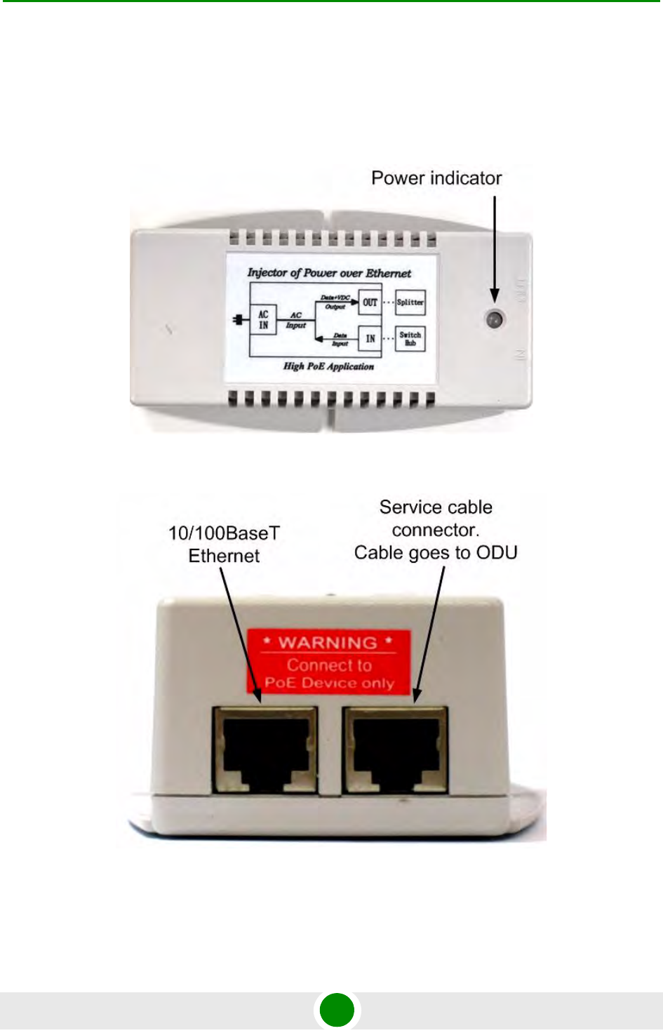
2.1.1 IDU-BS
Figure 2-1: IDU-BS Top View
Figure 2-2: IDU-BS Front Panel
Chapter 2 - Hardware Description Power supply units (IDU)
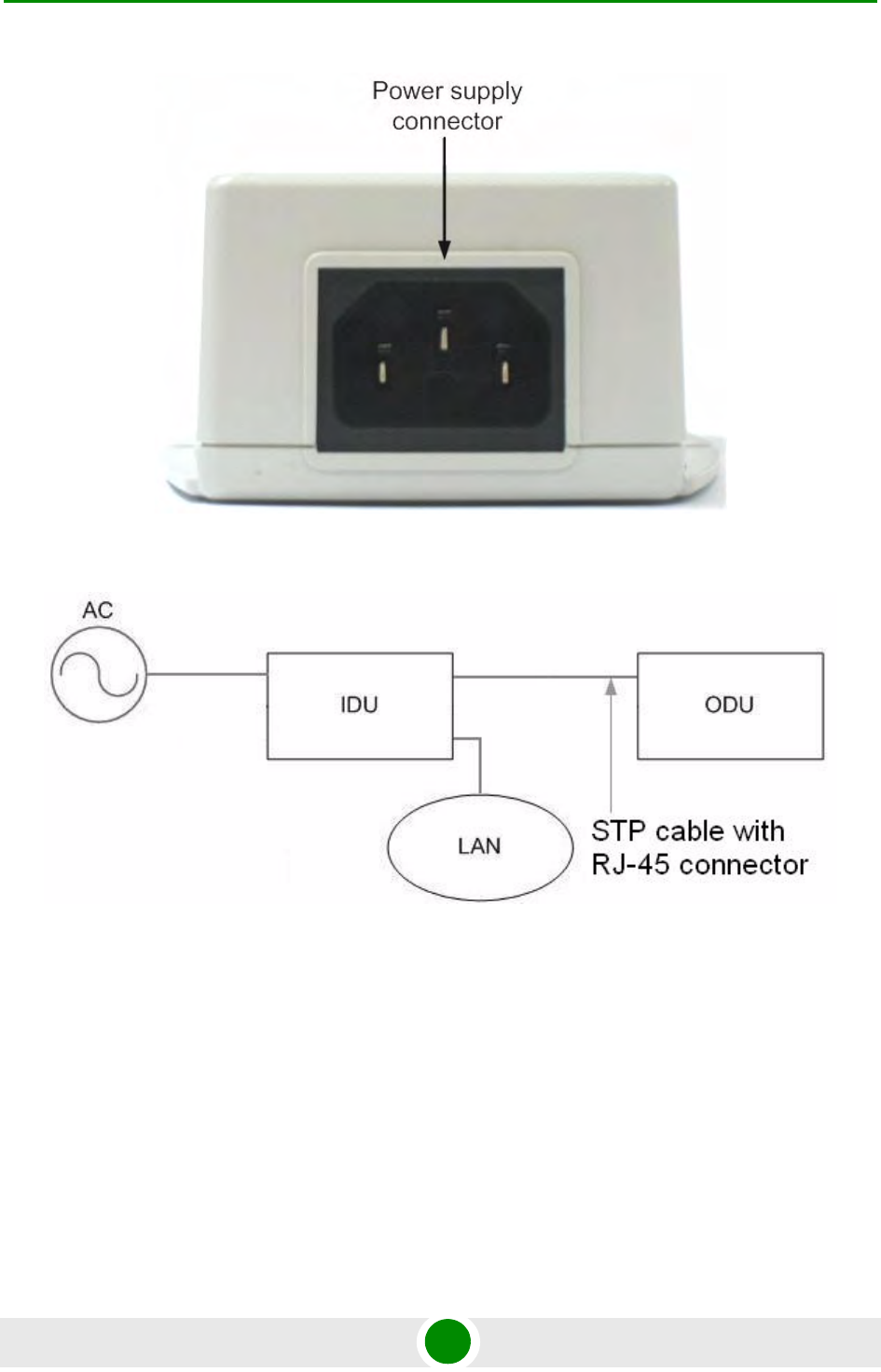
Alvarion BreezeNET B300 9 Technical User Manual
Figure 2-3: IDU-BS Rear Panel
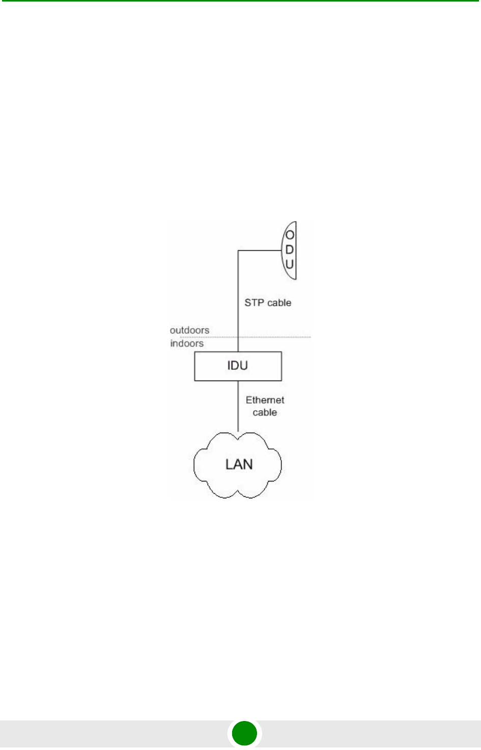
Figure 2-4: Connection scheme for IDU-BS
Chapter 2 - Hardware Description Outdoor Units (ODU)
Alvarion BreezeNET B300 10 Technical User Manual
2.2 Outdoor Units (ODU)
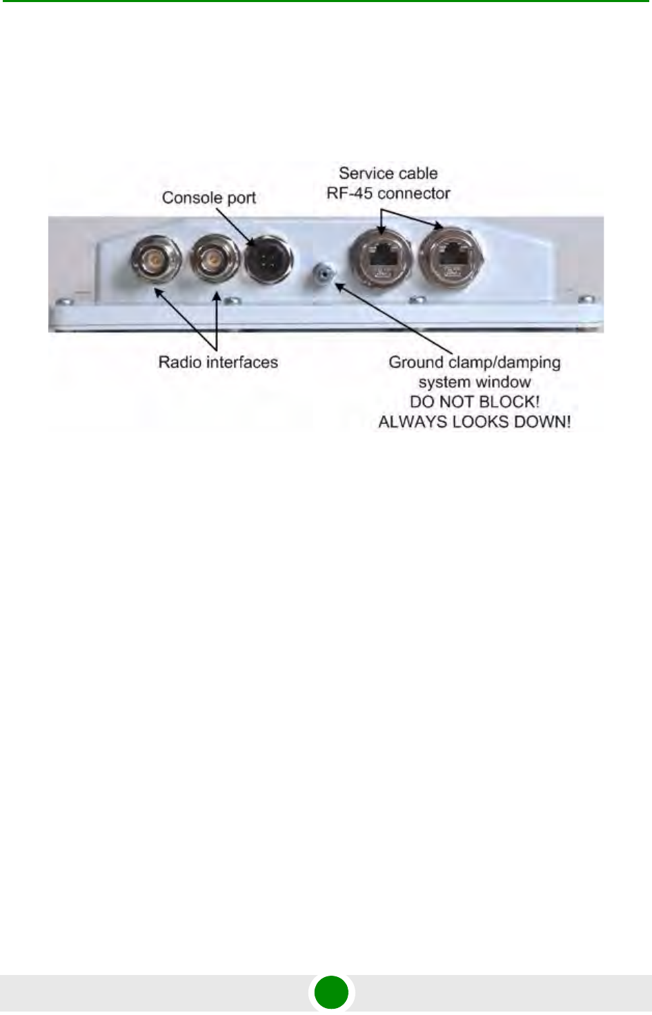
2.2.1 BU/RB-B300D-5X
Figure 2-5: BU/RB-B300D-5X Front Panel
Chapter 2 - Hardware Description Outdoor Units (ODU)
Alvarion BreezeNET B300 11 Technical User Manual
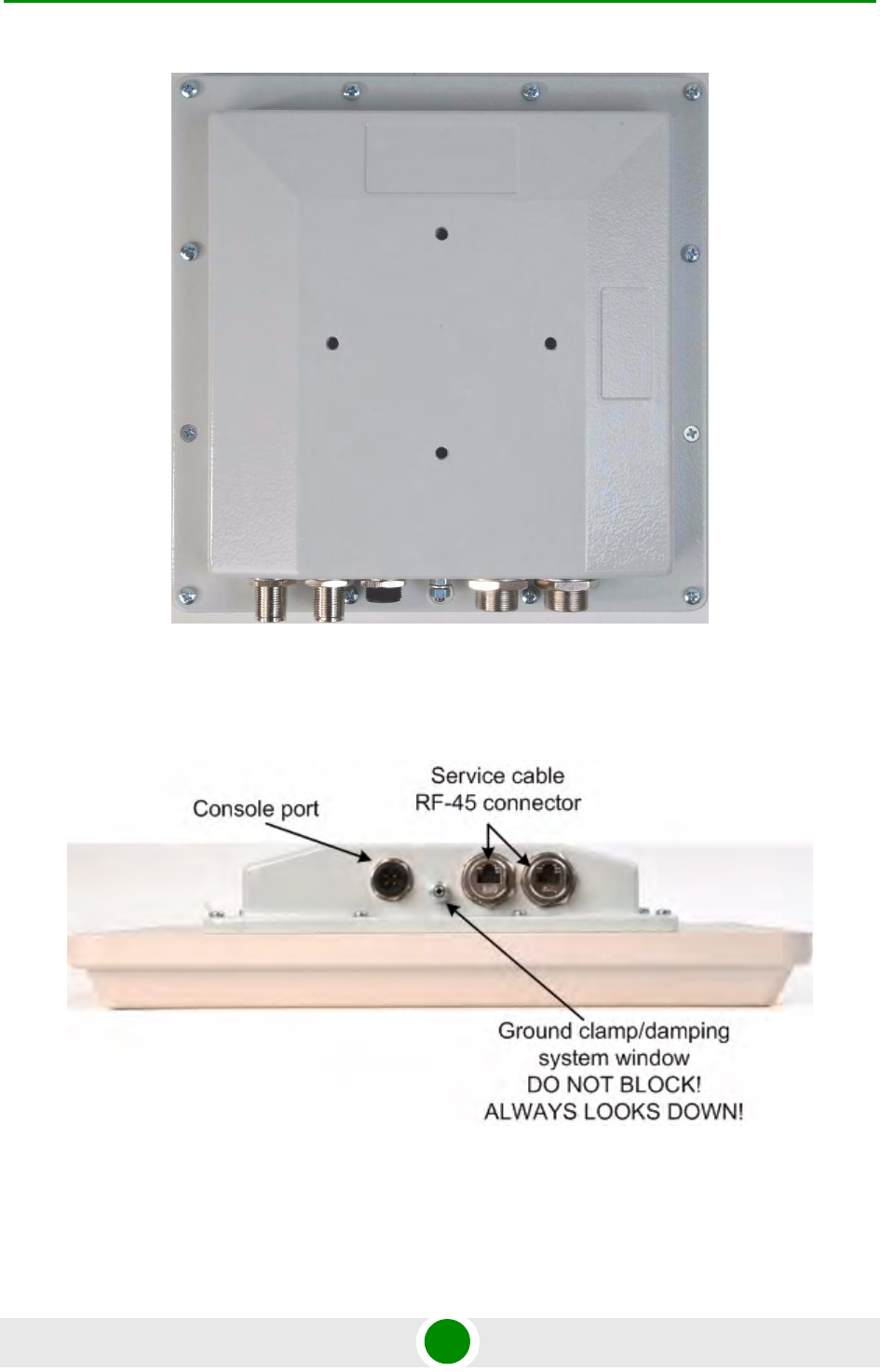
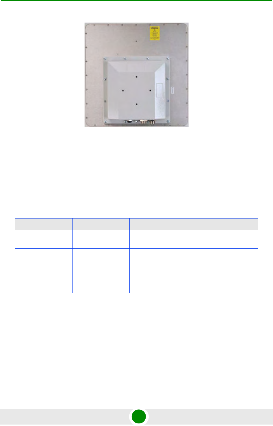
2.2.2 BU/RB-B300-5X
Figure 2-6: BU/RB-B300D-5X Top View
Figure 2-7: BU/RB-B300-5X Front Panel
Chapter 2 - Hardware Description Outdoor Units (ODU)
Alvarion BreezeNET B300 12 Technical User Manual
2.2.3 ODU LED Indicators Description
ODU units have two LED indicators (red and green) located in the Console
connector. These LEDs are useful in monitoring the device status during the
installation procedure. LEDs modes and Device status correspondence is shown
in the following table:
Figure 2-8: BU/RB-B300-5X Top View
Table 2-1: ODU LED Indicators Description
Red Indicator Green Indicator Device Status
Off Off Device is switched off of in the process of start-up
booting
Off Blinking Device is booted. No radio connection. Searching for
another device to establish radio connection to.
Blinking On Radio connection established. The more data is
transmitted through the radio channel the more
frequently red indicator is blinking.

Chapter 2 - Hardware Description Installation Preparations
Alvarion BreezeNET B300 13 Technical User Manual
2.3 Installation Preparations
2.3.1 Required Components and Accessories
Before the installation, please make sure you have all necessary parts and
accessories:
Device
Antenna
Low loss antenna cable for the required frequency range
Antenna pole (if necessary)
Required grounding system
Accessories and tools
2.3.2 Antenna Placement
When planning an antenna placement for PTP link, in order to obtain the maximal
coverage range and best performance for the Device, one need to consider that
LOS requirements must be fulfilled for the path between two antennas. Moreover,
it is of vital importance that the certain zone that surrounds the signal
propagation path must be free from obstructions. One should understand that the
radio beam is not as thin as, for example, laser beam. Radio beam, also called as
a 1st Fresnel zone, has a profile of a rugby ball. Its exact form and size depend
upon the frequency and the signal propagation path length.
If most of the 1st Fresnel zone is obstructed, a major part of a electromagnetic
energy will be lost which leads to a severe signal quality degradation and, as a
result, to coverage range decreasing.
Below is an incomplete list of possible obstructions on the signal propagation
path:
Neighboring buildings
Trees
Bridges

Chapter 2 - Hardware Description Installation Preparations
Alvarion BreezeNET B300 14 Technical User Manual
Power lines
To obtain the best results, it is necessary to perform a precise analysis of a signal
propagation path zone and possible obstructions that may cover a part of the 1st
Fresnel zone (usually the analysis is performed at the highest points of the signal
propagation path).
General recommendation for antennas placement are the following:
Install antennas as high as possible over specific level. In case of flat surface -
it will be ground level, in case of vegetation and forest - it will be tree heights,
in urban environment - it will be the highest building in the observed area
(specific level definition).
Avoid tree and vegetation along with wave propagation path, influence of trees
can increase depending on seasons (ice, dew, leaves);
Proximity of other antennas should be avoided (at least 2 meters);
Reflecting surfaces should be considered (building with reflective windows,
water surfaces or wet grounds);
When installing antenna over water surface, one should tune height bracket
within 1-3 meter range variation, because it can yield signal level variation
from minimum to maximum.
If seasonal changes influence on the signal quality, so then the most probable
reasons would be either the connectors are not protected enough from
humidity, summer vegetation or ice covered cabling and connectors during
winter.
NOTE
While planning, it is strongly recommended to consult high-qualified and experienced technicians
NOTE
Antenna installation must be performed only by a professional installer.
The system must be configured only as point to point. The maximum power at the antenna
connector , described in Table 2-3 and Table 2-4, is applicable for both qualified antennas and
for each channel bandwidth

Chapter 2 - Hardware Description Installation Preparations
Alvarion BreezeNET B300 15 Technical User Manual
2.3.3 Antenna Poles Usage
Antenna installation is performed on a special facility called antenna pole. The
pole is used for strong antenna tightening at the installation site. Poles might have
different modifications depending on the installation requirements.
2.3.4 Poles with Stretching
Usually this kind of poles are used when installing antenna on a flat surface and
permits one to raise it to a significant height for providing optimal conditions for
signal propagation.
2.3.5 Wall Mounted Pole
Usually these kinds of poles are used when there is no need to elevate antenna to
the rooftop and there is the possibility to mounting it on a wall. This installation is
significantly simpler than that implementation with poles. Mostly it is used for
subscriber side deployments.
2.3.6 Antenna Poles Requirements
Ease of antenna mounting and sufficient mechanical durability should provide
reliable fastening in conditions of high windy loads. Poles should have round
profile for ease of azimuth adjustment. Typical pole diameter is 30 to 50 mm.
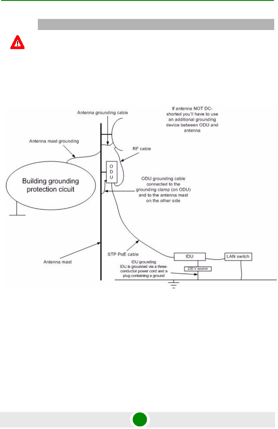
2.3.7 Grounding when Using IDU-BS
Antenna should be placed on the mast on the level that is at least 1 meter lower
than a mast's top. In this case it is of big probability that the lightning strikes the
mast and not the antenna. The mast is to be grounded on the grounding contour
according to your local standards. When the lightning strikes the antenna, the
current goes through the coaxial cable which grounds ODU clamp with the mast
- the mast is grounded via the grounding contour. The direct lightning strike to
the STP service cable (ODU-IDU) is partially terminated on the grounded IDU
case. Partial termination means that the direct lightning strike will probably
destroy an STP cable. The service cable pickups from the electromagnetic
impulses are terminated on the IDU case by the winding shield, and further - on
the IDU grounding. IDU is grounded via a three-conductor power cord and a plug
containing a ground. The data & power wires pickups are terminated via IDU
protection scheme (three-conductor power cord and a plug containing a ground).
Chapter 2 - Hardware Description Installation Preparations
Alvarion BreezeNET B300 16 Technical User Manual
A special attention should be paid if antenna used is not DC-shorted. In this case
additional lightning arrestor should be used between the antenna and ODU.
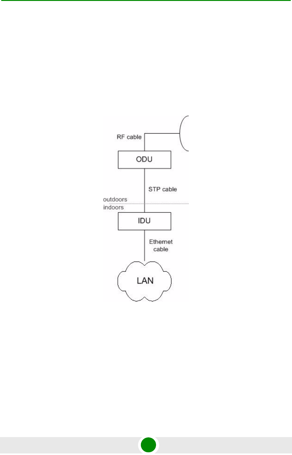
Suggested grounding diagram is shown on the picture below.
2.3.8 Antenna Alignment
To obtain maximal system performance antennas must be precisely aligned one
towards another according to LOS requirements. General recommendations for
antenna alignment are the following:
Align antennas using optical equipment (binoculars, spyglass) accompanied
by mobile phone actions coordination
CAUTION
Antenna pole, tower, ODU and lightning arrestor should be connected to the first common
grounding contour. Cable thickness should be no less than 10AWG using corrosion-steady
connectors. It is highly recommended to entrust grounding contour development to the skilled
personnel.
Figure 2-9: Grounding

Chapter 2 - Hardware Description Installation Preparations
Alvarion BreezeNET B300 17 Technical User Manual
Use GPS receiver and area map
Use build-in Device features. These features allow evaluating current
channel/signal quality and perform precise antenna alignment
2.3.9 Precaution Measures
Before you start the installation please read this section very carefully.
Antennas are installed on the roof tops or on the building walls. This work must
be accomplished only by personnel having special skills and experience in this
area.
Antennas and cables are electric conductors. Incidental electrostatic strikes may
occur during the system installation. This can lead to equipment damaging or
may hurt the personnel. While installing or changing the elements of the
antenna-fider system one should make sure that open metal parts are temporarily
grounded.
Do not install the antenna close to the electric power lines. Antenna and antenna
pole have to be installed in such a way that while their assembling, disassembling
and repairing they did not have any contact with power lines.
Basic precaution measures that must be fulfilled during the installation are the
following:
Do not stay on the roof top in windy or rainy weather, during the
thunderstorm or when the working zone is covered with snow or ice
Do not touch the antennas, antenna poles, cables and lighting arrestors
during the thunderstorm
Antenna placement should not be close to electric or telephone lines. Safe
distance is a distance that is a sum of the two antenna poles heights and
antenna height
2.3.10 Service Cable Soldering Procedure
The following instruction shows the "RJ-45" (modification 2) connector soldering
procedure.
Chapter 2 - Hardware Description Installation Preparations
Alvarion BreezeNET B300 18 Technical User Manual
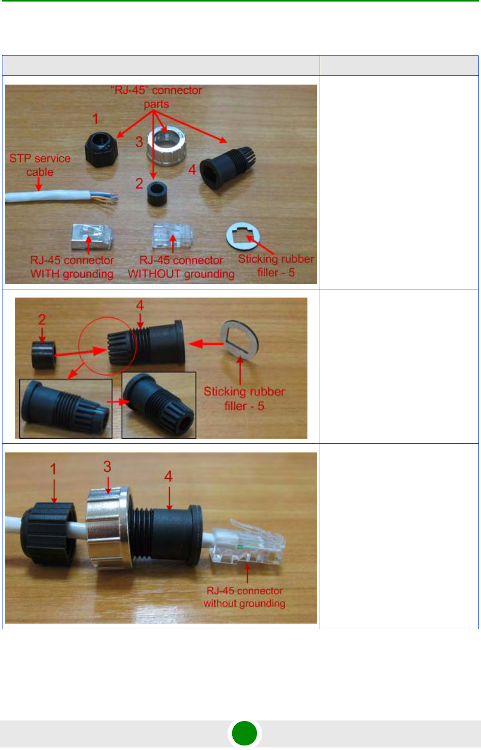
Table 2-2: RJ-45 Connector Soldering Procedure
Illustration Description
Step 1. Peel STP service cable and
prepare "RJ-45" connector parts.
Use RJ-45 connector without
grounding here (RJ-45 connector
with grounding is used for
connecting service cable to IDU).
Step 2. Stick rubber filler - 5 on the
Part 4, previously having removed
protective white layer from rubber
filler -5.
Insert Part 2 inside part 4 up to the
stop. Part 2 must be entirely within
Part 4.
Step 3. Put connector parts on the
STP service cable as shown.
Attach RJ-45 connector without
grounding to the STP service cable
according to the "RJ-45" soldering
scheme and crimp the connector.
Chapter 2 - Hardware Description Installation Preparations
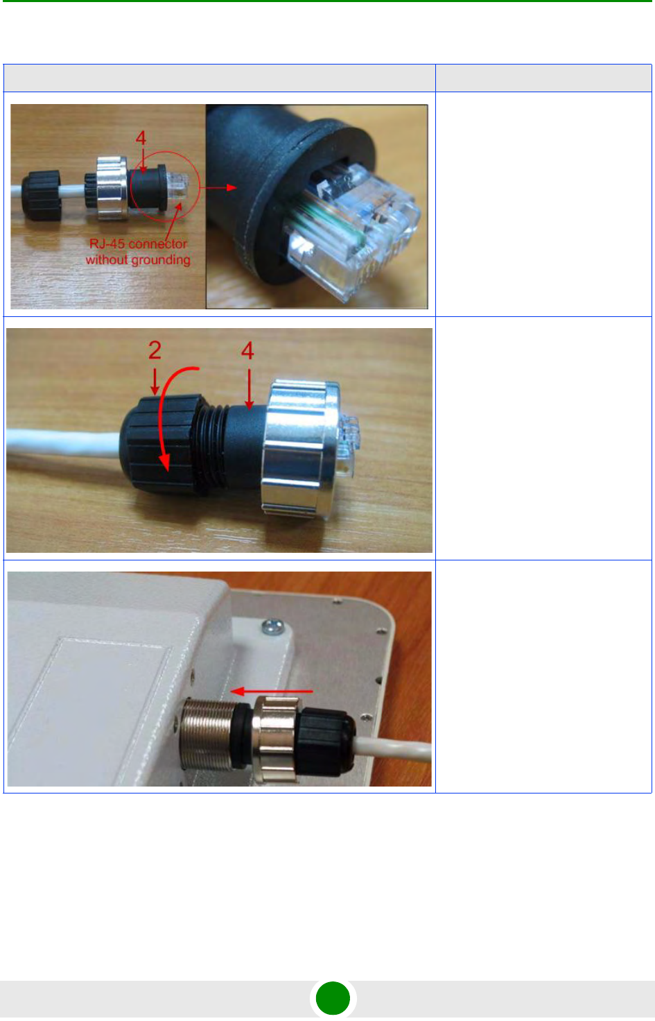
Alvarion BreezeNET B300 19 Technical User Manual
Step 4. Put Part 4 on the attached in
the previous step RJ-45 connector.
Step 5. Screw Part 2 on Part 4. This
fixes the "RJ-45" connector on the
cable. Check that the connector is
properly fixed on the cable.
Step 6. Assemble the connector to
the unit.
Table 2-2: RJ-45 Connector Soldering Procedure
Illustration Description
Chapter 2 - Hardware Description Installation Preparations
Alvarion BreezeNET B300 20 Technical User Manual
2.3.11 Tools Required at the Installation Site
1Screwdrivers set
2Pliers
3Soldering iron 40 W
4Spanners set
5Connectors isolating set
»Raw rubber
»Thermal shrinkage tube
»Scissors
»Fan
»Mantling gun
6Additional equipment
»GPS receiver or area map (with compass and alidade)
»Big zoom binoculars
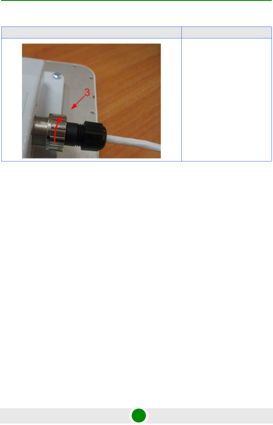
Step 7. Fix the connector by
screwing Part 3.
Now the connector is hermetically
attached to the unit.
Table 2-2: RJ-45 Connector Soldering Procedure
Illustration Description
Chapter 2 - Hardware Description BU/RB-B300D-5X
Alvarion BreezeNET B300 21 Technical User Manual
2.4 BU/RB-B300D-5X
2.4.1 Installation Guidelines
1Unpack the equipment
2Check items integrity
3Prepare RF-cables of the required length. The recommended maximal RF cable
length is 1 meter.
4Install and isolate the connectors on the RF cables
5Determine the STP cable length that is used to connect IDU and ODU. The
total cable length between LAN (behind IDU) and ODU should not be longer
than 100 meters. Service cable connecting IDU and ODU should be STP Cat
5E cable.
6Install (solder) connector for ODU on the STP cable and isolate it
7If it is possible to lay STP cable with a connector on the IDU side, install
(solder) connector for IDU on the STP cable and isolate it
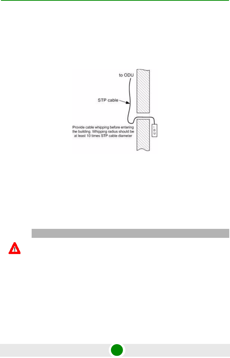
8Lay the STP cable "from top to bottom" - from ODU to IDU
9If step 7 is not accomplished, after the STP cable has been laid, install (solder)
connector for IDU
10 Install ODU on the mounting bracket connectors down and tighten it
Figure 2-10: BU/RB-B300D-5X Installation 1
Chapter 2 - Hardware Description BU/RB-B300D-5X
Alvarion BreezeNET B300 22 Technical User Manual
11 Connect the ODU-IDU cable to the ODU
12 Isolate the ODU connector joint place
13 Once the antenna and antenna pole are installed they must be grounded via
lightning protection grounding contour. Antenna's position must be lower than
the highest antenna pole point at least by 2 antenna heights. If antenna is
NOT DC-shorted (see antenna technical documentation), the additional
lightning arrestor must be used which is placed between ODU and antenna
and is grounded to the antenna pole grounding contour.
14 Connect RF cables to the antenna. Twist the connectors tightly
15 Connect RF cables to the ODU previously having touched RF cable connectors
case with ODU connector case
16 Isolate RF connectors from both sides (ODU and antenna)
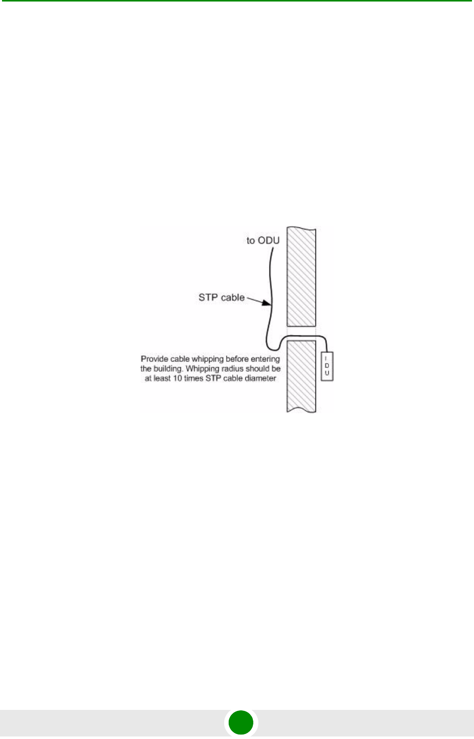
17 Connect the STP cable to IDU previously having touched IDU connector case
with STP cable connector case
18 Provide grounding for IDU
Figure 2-11: BU/RB-B300D-5X Installation 2
Chapter 2 - Hardware Description BU/RB-B300D-5X
Alvarion BreezeNET B300 23 Technical User Manual
19 Connect Ethernet cable to IDU
20 Provide power supply for IDU
21 Connect to the Device using Telnet protocol
2.4.2 Tube Mounting for ODU
CAUTION
It is extremely important to install ODU connectors down!
Figure 2-12: Tube Mounting 1
Chapter 2 - Hardware Description BU/RB-B300D-5X
Alvarion BreezeNET B300 24 Technical User Manual
Figure 2-13: Tube Mounting 2
Chapter 2 - Hardware Description BU/RB-B300-5X
Alvarion BreezeNET B300 25 Technical User Manual
2.5 BU/RB-B300-5X
2.5.1 Installation Guidelines
1Unpack the equipment
2Check items integrity
3Determine the STP cable length that is used to connect IDU and ODU. The
total cable length between LAN (behind IDU) and ODU should not be longer
than 100 meters.
4Install (solder) connector for ODU on the STP cable and isolate it
5Lay the STP cable "from top to bottom" - from ODU to IDU
6After the STP cable has been laid, use distribution box to switch from STP
cable to UTP cable with RJ-45 connectors. Service cable connecting IDU and
ODU should be STP Cat 5E cable.
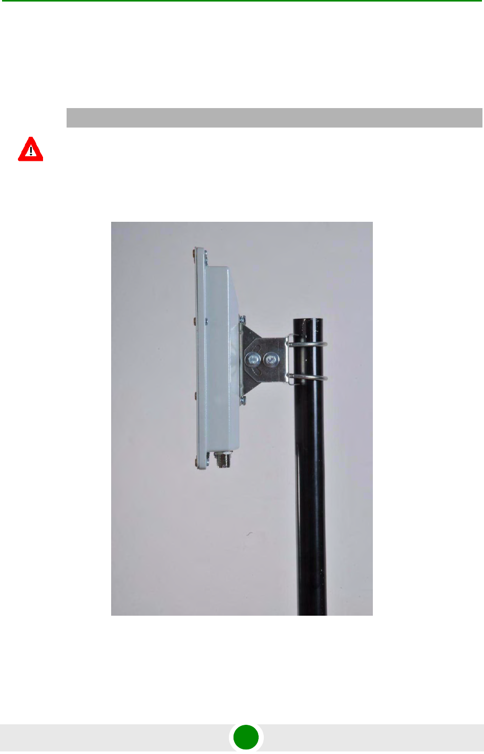
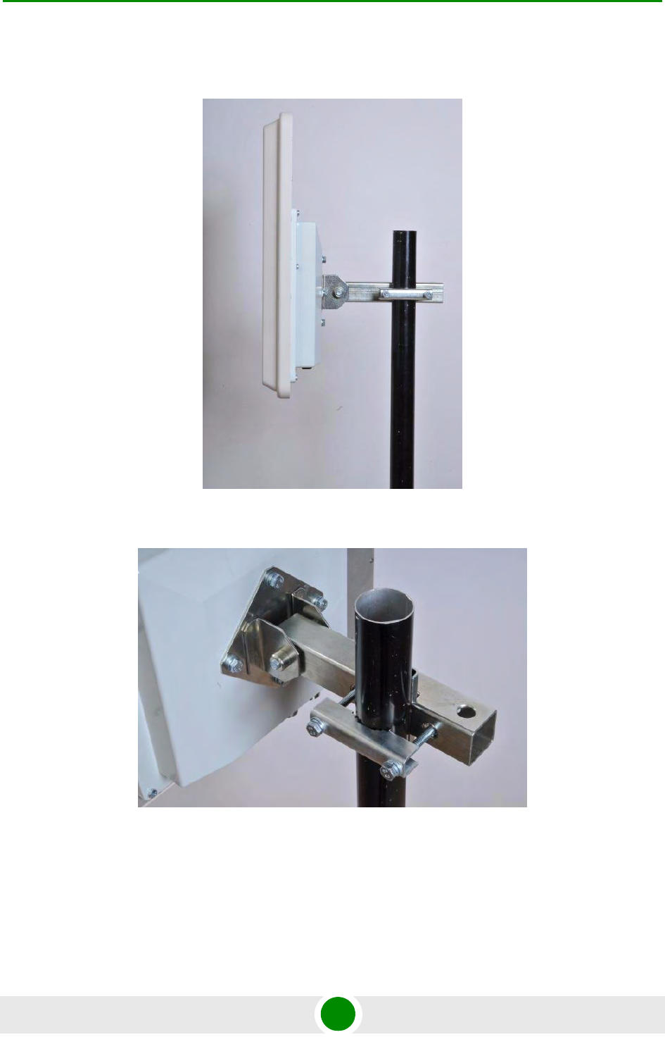
7Install ODU on the mounting bracket according to the direction required for
the link. Do not tight it too hard unless the antenna alignment is not complete.
Install ODU connectors down.
Figure 2-14: BU/RB-B300-5X Installation 1
Chapter 2 - Hardware Description BU/RB-B300-5X
Alvarion BreezeNET B300 26 Technical User Manual
8Connect the ODU-IDU cable to the ODU
9Isolate the ODU connector joint place
10 Once the ODU and antenna pole are installed they must be grounded via
lightning protection grounding contour. ODU position must be lower than the
highest antenna pole point at least by 2 ODU heights
11 Connect the UTP cable to IDU
12 Provide grounding for IDU
13 Connect Ethernet cable to IDU
14 Provide power supply for IDU
15 Connect to the Device using Telnet protocol
Figure 2-15: BU/RB-B300-5X Installation 2
CAUTION
It is extremely important to install ODU connectors down!
Chapter 2 - Hardware Description BU/RB-B300-5X
Alvarion BreezeNET B300 27 Technical User Manual
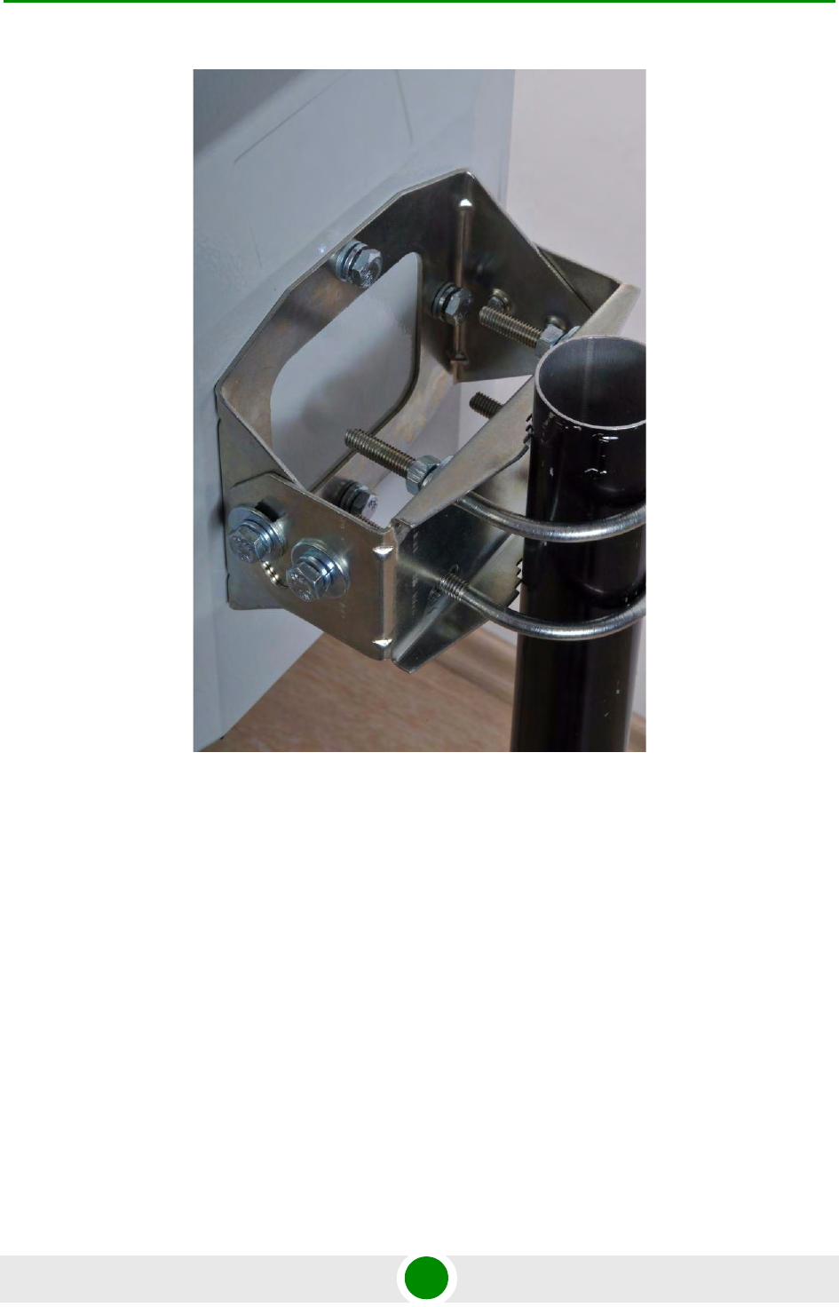
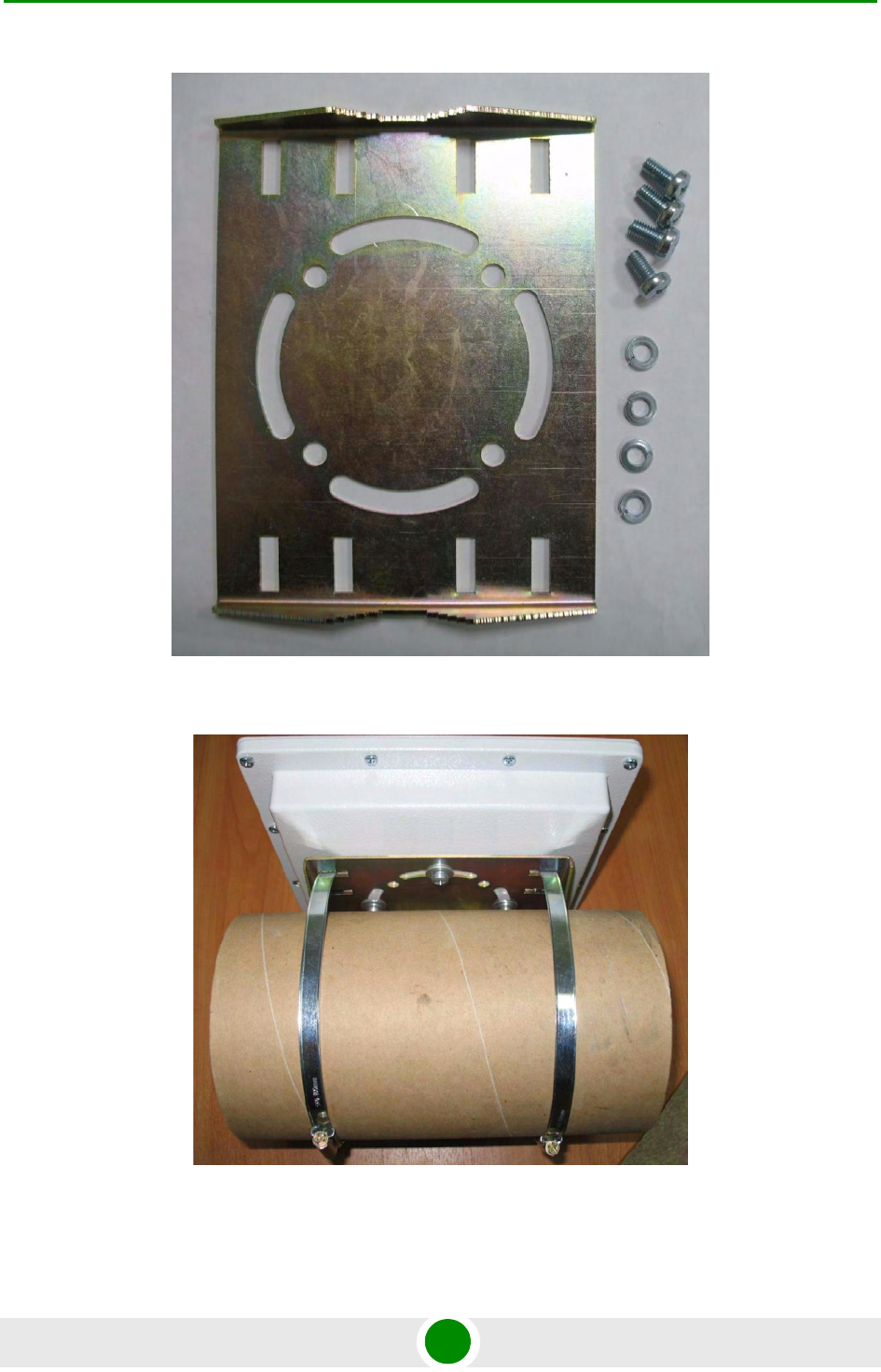
2.5.2 Pole Mounting Kit Assembling
Figure 2-16: Pole Mounting Kit Assembling 1
Figure 2-17: Pole Mounting Kit Assembling 2
Chapter 2 - Hardware Description Mounting Kits Assembling
Alvarion BreezeNET B300 28 Technical User Manual
2.6 Mounting Kits Assembling
2.6.1 Pole Mounting Kit MONT-5000-V.Pole-KIT for
Vertical Mast
CAUTION
Attention! Pole mounting kit MONT-5000-V.Pole-KIT does NOT contain metal straps.
Figure 2-18: MONT-5000-V.Pole-KIT 1
Chapter 2 - Hardware Description Mounting Kits Assembling
Alvarion BreezeNET B300 29 Technical User Manual
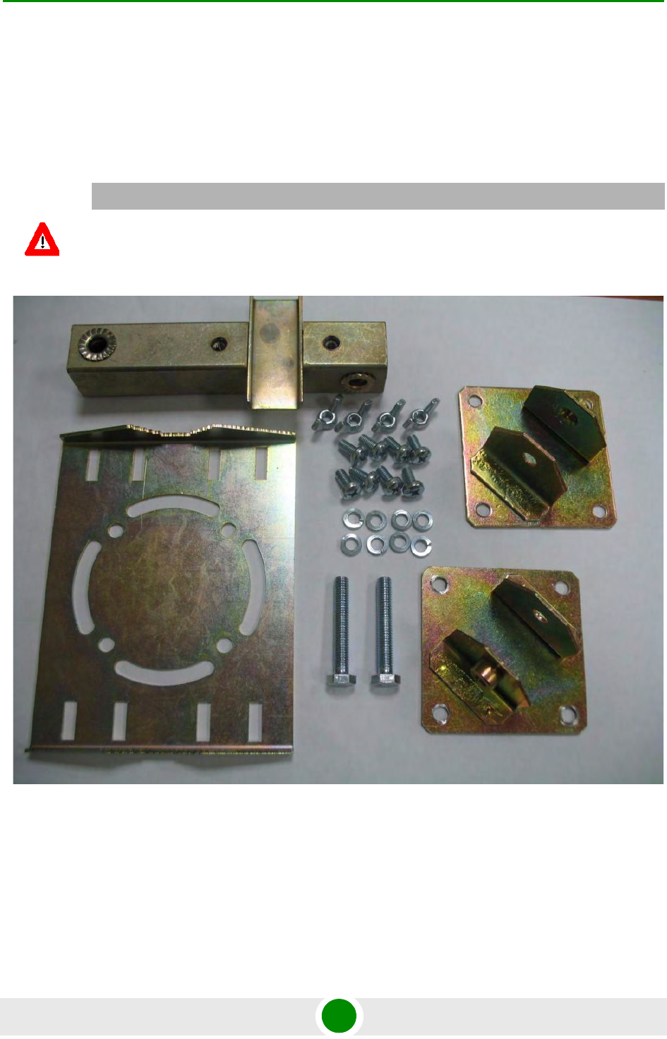
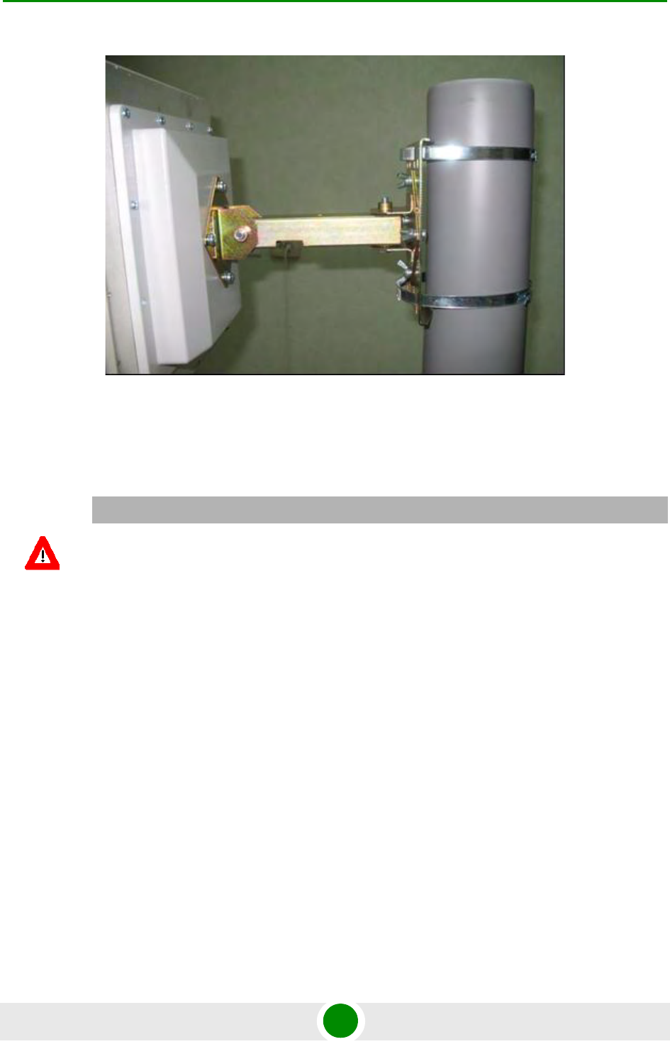
2.6.2 Pole Mounting Kit MONT-5000-H.Pole-KIT for
Horizontal Pole
Figure 2-19: MONT-5000-V.Pole-KIT 2
CAUTION
Attention! Pole mounting kit MONT-5000-H.Pole-KIT does NOT contain metal straps.
Chapter 2 - Hardware Description Mounting Kits Assembling
Alvarion BreezeNET B300 30 Technical User Manual
Figure 2-20: MONT-5000-H.Pole-KIT 1
Figure 2-21: MONT-5000-H.Pole-KIT 2

Chapter 2 - Hardware Description Specifications
Alvarion BreezeNET B300 31 Technical User Manual
2.7 Specifications
2.7.1 Radio
Table 2-3: Radio Specifications
Item Description
Frequency ETSI (5.470 - 5.725 GHz) Center frequencies range 5.475 - 5.720 GHz
(in 5MHz steps) for 5MHz BW
Center frequencies range 5.475 - 5.720 GHz
(in 5MHz steps) for 10MHz BW
Center frequencies range 5.480 - 5.700 GHz
(in 20MHz steps) for 20MHz BW
Center frequencies range 5.490 - 5.690 GHz
(in 20MHz steps) for 40MHz BW
ETSI (5.725 - 5.875 GHz) Center frequencies range 5.730 - 5.870 GHz
(in 5MHz steps) for 5MHz BW
Center frequencies range 5.730 - 5.870 GHz
(in 5MHz steps) for 10MHz BW
Center frequencies range 5.740 - 5.860 GHz
(in 20MHz steps) for 20MHz BW
Center frequencies range 5.750 - 5.850 GHz
(in 20MHz steps) for 40MHz BW
FCC (4.940 - 4.990 GHz) Center frequencies range 4.945 - 4.985 GHz
(in 5MHz steps) for 5MHz BW
Center frequencies range 4.945 - 4.985 GHz
(in 5MHz steps) for 10MHz BW
Center frequencies range 4.960 GHz for
20MHz BW
Center frequencies range 4.970 GHz for
40MHz BW

Chapter 2 - Hardware Description Specifications
Alvarion BreezeNET B300 32 Technical User Manual
FCC (5.250 - 5.350 GHz) Center frequencies range 5.255 - 5.345 GHz
(in 5MHz steps) for 5MHz BW
Center frequencies range 5.255 - 5.345 GHz
(in 5MHz steps) for 10MHz BW
Center frequencies range 5.260 - 5.340 GHz
(in 20MHz steps) for 20MHz BW
Center frequencies range 5.270 - 5.330GHz (in
20MHz steps) for 40MHz BW
FCC (5.470 - 5.725 GHz) Center frequencies range 5.475 - 5.720 GHz
(in 5MHz steps) for 5MHz BW
Center frequencies range 5.475 - 5.720 GHz
(in 5MHz steps) for 10MHz BW
Center frequencies range 5.480 - 5.700 GHz
(in 20MHz steps) for 20MHz BW
Center frequencies range 5.490 - 5.690 GHz
(in 20MHz steps) for 40MHz BW
FCC (5.725 - 5.850 GHz) Center frequencies range 5.730 - 5.845 GHz
(in 5MHz steps) for 5MHz BW
Center frequencies range 5.730 - 5.845 GHz
(in 5MHz steps) for 10MHz BW
Center frequencies range 5.740 - 5.840 GHz
(in 20MHz steps) for 20MHz BW
Center frequencies range 5.750 - 5.830 GHz
(in 20MHz steps) for 40MHz BW
Universal Center frequencies range 4.915 - 5.945 GHz
(in 5MHz steps) for 5MHz BW
Center frequencies range 4.915 - 5.945 GHz
(in 5MHz steps) for 10MHz BW
Center frequencies range 4.920 - 5.940 GHz
(in 20MHz steps) for 20MHz BW
Center frequencies range 4.930 - 5.930 GHz
(in 20MHz steps) for 40MHz BW
Modulation OFDM modulation, BPSK, QPSK, QAM16, QAM64
Radio Type OFDM TDD
Channel BW 5 MHz / 10 MHz / 20 MHz / 40 MHz
Maximal Net Throughput 250 Mbps
Table 2-3: Radio Specifications
Item Description

Chapter 2 - Hardware Description Specifications
Alvarion BreezeNET B300 33 Technical User Manual
2.7.2 Antenna
2.7.3 Data Communication
Output Power (at antenna port) Up to 18 dBm (dependant upon regulation)
Table 2-4: Maximum Peak Channel Power Levels
Channel Bandwidth Max. Total Channel Power (Peak)
(dBm)
5 MHz 25.6
10 MHz 24.18
20 MHz 23.58
40 MHz 21.8
Table 2-5: Antenna Specifications
Item Description
External Antenna ANT, T.S, 4.9-6 GHz, 9°, dual polarized, 23 dBi / ANT, T.S, 4.9-6
GHz, 6°, dual polarized, 28 dBi
Integrated Antenna ANT, T.S, 4.9-6 GHz, 9°, dual polarized, 23 dBi
Table 2-6: Data Communication Specifications
Item Description
Standard and Network Compliance IEEE 802.3 CSMA CD, ARP filter/proxy, MAC/IP filtering, layer 2
switch, 2x Ethernet 10/100BaseT
VLAN Support 802.1q transparent or frame tagging and re-tagging
QoS QoS enforcer classification and traffic limiting based on: IP
ToS/DSCP/802.1p tags, VLAN/IP/MAC address and protocol
Security Storm/flood protection, password protection, over-the-air payload
encryption, IP Firewall
Table 2-3: Radio Specifications
Item Description

Chapter 2 - Hardware Description Specifications
Alvarion BreezeNET B300 34 Technical User Manual
2.7.4 Configuration Management
2.7.5 Electrical Characteristics
2.7.6 Physical and Environmental
Table 2-7: Configuration Management Specifications
Item Description
Management Options Configure/monitor SNMP traps, WEB interface, CLI (telnet, serial
console, remote shell)
Remote Management Access From wired LAN, wireless link
Allocation of IP Address DHCP client / server / relay
SW Upgrade Via FTP / WEB interface
Configuration Upload / Download Via FTP / WEB interface
SNMP Agents SNMP V1 / SNMP V3, MIB II, private MIB
Table 2-8: Electrical Characteristics Specifications
Item Description
Power Consumption Up to 20W
Input Power AC, 100-240 VAC, 50-60 Hz (DC 10.5-32 UDC with OPS-DC add-on
module)
Indoor-outdoor Cable CAT-5 shielded, 90m max
AC Power Indoor Unit 3 pin AC power plug
Connectors RJ-45
Table 2-9: Physical and Environmental Specifications
Item Description
Dimensions RB/BU IDU: 5 x 4 x 2 cm (0.14 kg) / ODU with integrated antenna: 30 x 30 x
8 cm (3.7 kg) / ODU with external antenna 24 x 24 x 5 cm (2.1 kg)
Operating Temperature ODU: -40°C to 60°C / IDU: 0°C to 40°C
Operating Humidity ODU: 100% humidity, condensing (exceeds IP65 rating) / IDU: 95%
humidity, non-condensing

Chapter 2 - Hardware Description Specifications
Alvarion BreezeNET B300 35 Technical User Manual
2.7.7 Standards and Regulations
Table 2-10: Standards and Regulations Compliance
Item Description
Radio ETSI EN 301 893 V1.5.1 / ETSI EN 302 502 V1.2.1
EMC ETSI EN 301 489-1 V1.4.1
Protection and Safety ETSI EN 60950-1