Alvarion Technologies BNETB-5XGIGE BreezeNETB300 User Manual BreezeNET B130 B300 GigE Technical
Alvarion Technologies Ltd. BreezeNETB300 BreezeNET B130 B300 GigE Technical
UserManual.wiki
>
Alvarion Technologies
>
BNETB 5XGIGE User Manual
Users Manual
Navigation menu
Upload a User Manual
Namespaces
Wiki Guide
HTML
PDF
Info
Views
User Manual
Discussion / Help
Navigation
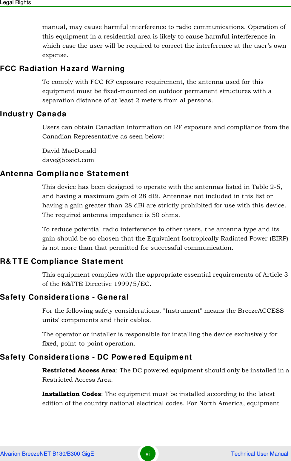
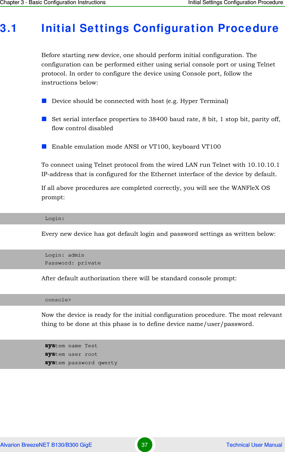
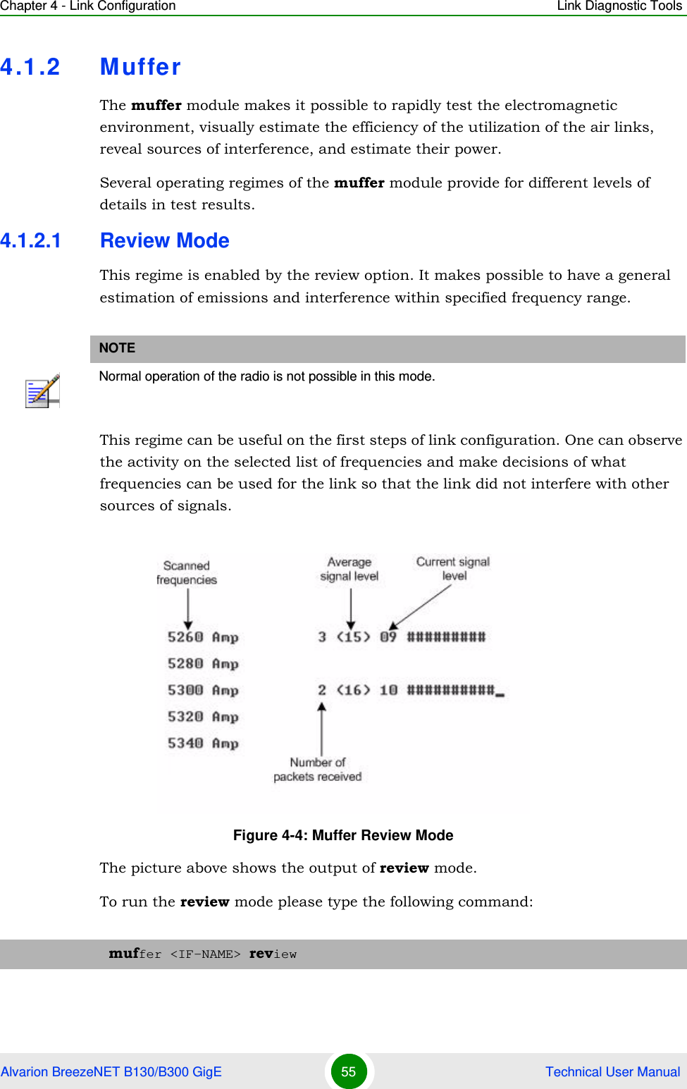
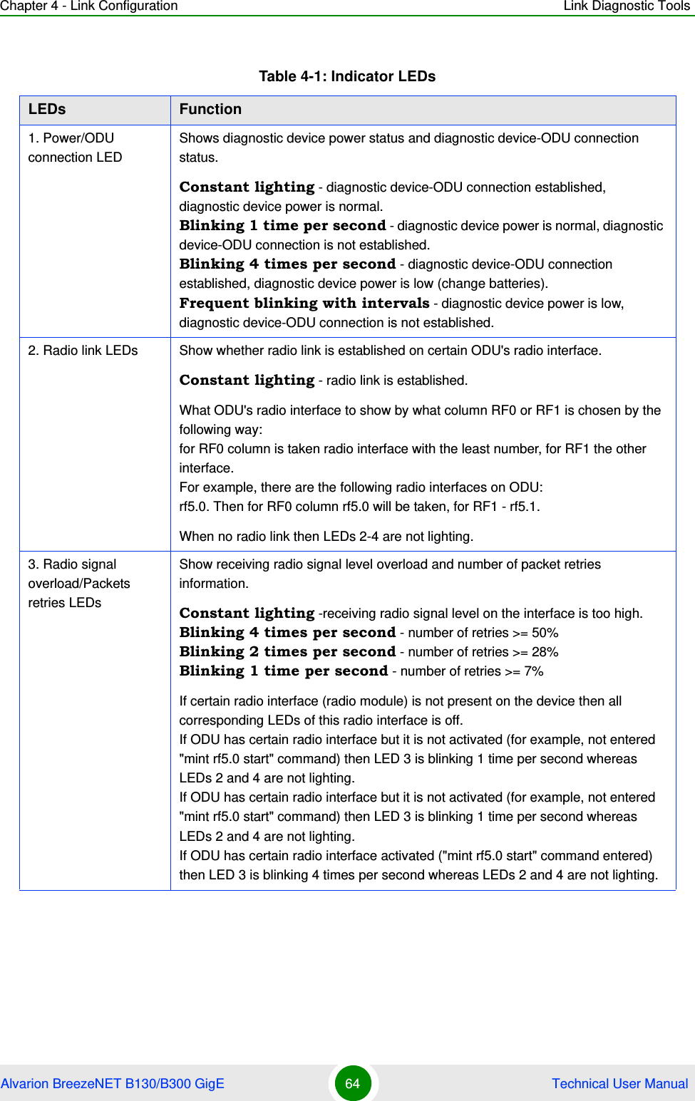
![Chapter 4 - Link Configuration Link Diagnostic ToolsAlvarion BreezeNET B130/B300 GigE 53 Technical User Manual1It is recommended to start antenna alignment with searching maximum signal level on a minimal possible bitrate. Afterwards automatic MINT mechanisms will set the most appropriate bitrate if autobitrate mode will be enabled.2Current incoming signal level in "amp/max" columns (see "ltest" command output) must be between 12 and 40.When it is more than 40 it is recommended to lower amplifier power.If maximal signal level is less than 12 it is recommended to lower bitrate or channel width (for example, from 20MHz to 10MHz on the both sides of the radio link).In some cases signal level that is less then 12 may be enough for radio link operation. In this case one has to be guided by such parameters as number of retries, number of undelivered packets and number of undelivered acks. If the number of undelivered packets and the number of undelivered acks is null, the number of retries is small and all these parameters are constant in time then the radio link, most often, will be operating properly.3Number of retries value in "rt%" columns must be as close to zero as possible.4Number of undelivered packets value in "up%" columns must be zero; if this value is not zero then the radio link couldn't be exploit.5Number of undelivered acks value in "ua%" columns must be zero; if this value is not zero then the radio link couldn't be exploit.ALL described parameters must be observed in the both (Local and Remote) sections of the "ltest" command output.Alignment mode:The difference of this mode from the standard one is that "ant.amps" column is used instead of "amp/max". "Ant.amps" column indicates signal levels for each of two antennas of a device divided by ":" correspondingly.To start Ltest in this mode:Ltest output in alignment mode:ltest rf5.0 <Mac-address> -align [L,R]](https://usermanual.wiki/Alvarion-Technologies/BNETB-5XGIGE/User-Guide-1384579-Page-69.png)
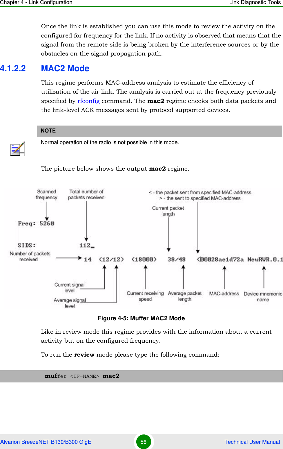
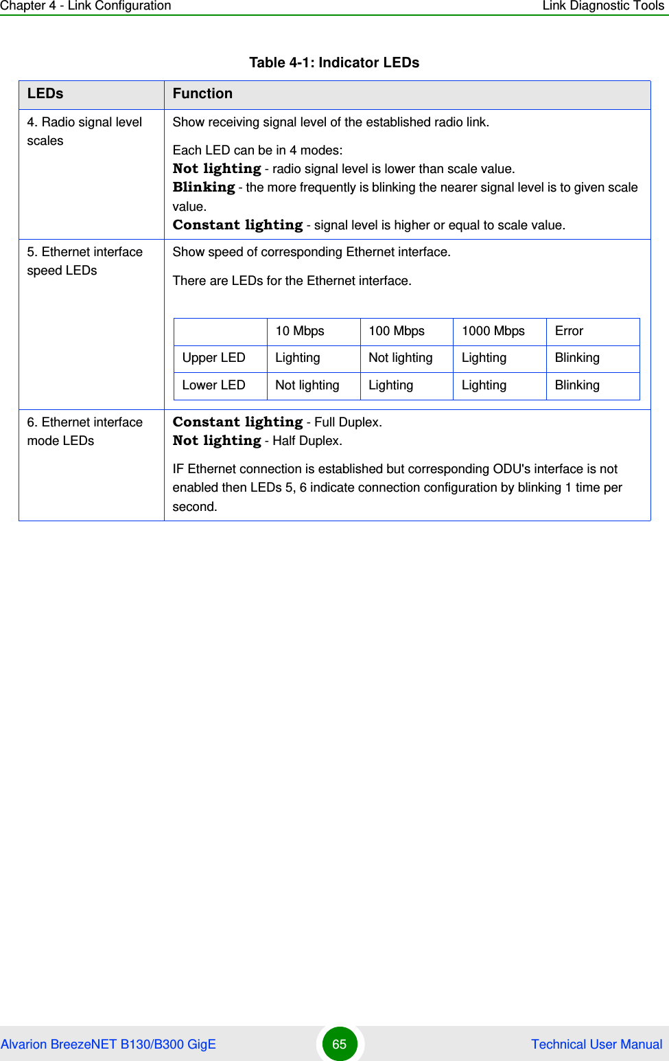
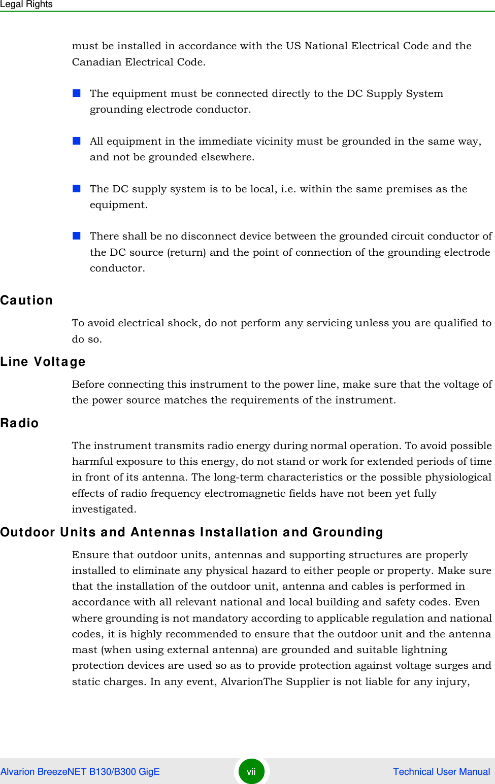
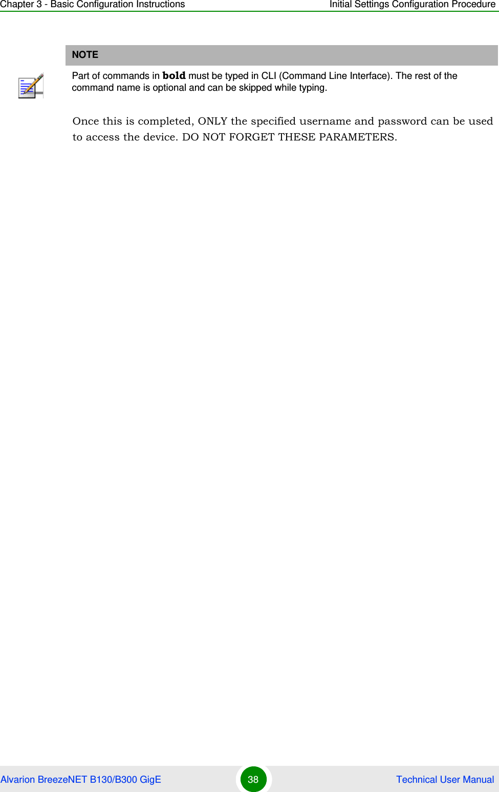
![Chapter 4 - Link Configuration Link Diagnostic ToolsAlvarion BreezeNET B130/B300 GigE 54 Technical User ManualBandwidth mode (Bandwidth meter):Bandwidth meter is used to test the following radio link characteristics: speed in kilobits per second, speed in packets per second, number of retries and errors.Use the following "ltest" command options for testing:-tu [seconds] - Unidirectional test: packets are transmitted only from the current side to the specified address ("target" option)-tb [seconds] - Bidirectional test: packets are transmitted in both directions"Seconds" parameter allows setting test period (5 seconds by default). Maximum value is 60 seconds.To start Ltest in this mode:"Ltest" command output in Bandwidth meter mode:Figure 4-2: Ltest Alignltest rf5.0 <Mac-address> -tbFigure 4-3: Ltest Bandwidth Meter](https://usermanual.wiki/Alvarion-Technologies/BNETB-5XGIGE/User-Guide-1384579-Page-70.png)