Alvarion Technologies COMPACT3X Base station transceiver User Manual Compact System Manual
Alvarion Technologies Ltd. Base station transceiver Compact System Manual
Contents
- 1. User manual, part 1
- 2. User manual, part 2
- 3. User manual
- 4. Response_FCC_22854_June-17-2012
User manual, part 1

BreezeCOMPACT
System Manual
Release Version: 1.0
December 2011
P/N

BreezeCOMPACT System Manual ii
Document History
Document History
Topic Description Date Issued
BreezeCOMPACT System Manual First publication of a System Manual for
a new product
March 2012

BreezeCOMPACT System Manual iii
Legal Rights
Legal Rights
© Copyright 2012 Alvarion Ltd. All rights reserved.
The material contained herein is proprietary, privileged, and confidential and owned by Alvarion or its
third party licensors. No disclosure thereof shall be made to third parties without the express written
permission of Alvarion Ltd.
Alvarion Ltd. reserves the right to alter the equipment specifications and descriptions in this publication
without prior notice. No part of this publication shall be deemed to be part of any contract or warranty
unless specifically incorporated by reference into such contract or warranty.
Trade Names
Alvarion®, BreezeCOM®, WALKair®, WALKnet®, BreezeNET®, BreezeACCESS®, BreezeLINK®,
BreezeMAX®, BreezeLITE®, BreezePHONE®, 4Motion®, and/or other products and/or services referenced
here in are either registered trademarks, trademarks or service marks of Alvarion Ltd.
All other names are or may be the trademarks of their respective owners.
“WiMAX Forum” is a registered trademark of the WiMAX Forum. “WiMAX,” the WiMAX Forum logo,
“WiMAX Forum Certified”, and the WiMAX Forum Certified logo are trademarks of the WiMAX Forum.
Statement of Conditions
The information contained in this manual is subject to change without notice. Alvarion Ltd. shall not be
liable for errors contained herein or for incidental or consequential damages in connection with the
furnishing, performance, or use of this manual or equipment supplied with it.
Warranties and Disclaimers
All Alvarion Ltd. (“Alvarion“) products purchased from Alvarion or through any of Alvarion's authorized
resellers are subject to the following warranty and product liability terms and conditions.
Exclusive Warranty
(a) Alvarion warrants that the Product hardware it supplies and the tangible media on which any
software is installed, under normal use and conditions, will be free from significant defects in materials
and workmanship for a period of fourteen (14) months from the date of shipment of a given Product to
Purchaser (the "Warranty Period"). Alvarion will, at its sole option and as Purchaser's sole remedy, repair
or replace any defective Product in accordance with Alvarion' standard R&R procedure.
(b) With respect to the Firmware, Alvarion warrants the correct functionality according to the attached
documentation, for a period of fourteen (14) month from invoice date (the "Warranty Period")". During
the Warranty Period, Alvarion may release to its Customers firmware updates, which include additional
performance improvements and/or bug fixes, upon availability (the "Warranty"). Bug fixes, temporary
patches and/or workarounds may be supplied as Firmware updates.
Additional hardware, if required, to install or use Firmware updates must be purchased by the Customer.
Alvarion will be obligated to support solely the two (2) most recent Software major releases.
ALVARION SHALL NOT BE LIABLE UNDER THIS WARRANTY IF ITS TESTING AND EXAMINATION DISCLOSE
THAT THE ALLEGED DEFECT IN THE PRODUCT DOES NOT EXIST OR WAS CAUSED BY PURCHASER'S OR
ANY THIRD PERSON'S MISUSE, NEGLIGENCE, IMPROPER INSTALLATION OR IMPROPER TESTING,
UNAUTHORIZED ATTEMPTS TO REPAIR, OR ANY OTHER CAUSE BEYOND THE RANGE OF THE INTENDED
USE, OR BY ACCIDENT, FIRE, LIGHTNING OR OTHER HAZARD.

BreezeCOMPACT System Manual iv
Legal Rights
Disclaimer
(a) The Software is sold on an "AS IS" basis. Alvarion, its affiliates or its licensors MAKE NO
WARRANTIES, WHATSOEVER, WHETHER EXPRESS OR IMPLIED, WITH RESPECT TO THE SOFTWARE AND
THE ACCOMPANYING DOCUMENTATION. ALVARION SPECIFICALLY DISCLAIMS ALL IMPLIED
WARRANTIES OF MERCHANTABILITY AND FITNESS FOR A PARTICULAR PURPOSE AND
NON-INFRINGEMENT WITH RESPECT TO THE SOFTWARE. UNITS OF PRODUCT (INCLUDING ALL THE
SOFTWARE) DELIVERED TO PURCHASER HEREUNDER ARE NOT FAULT-TOLERANT AND ARE NOT
DESIGNED, MANUFACTURED OR INTENDED FOR USE OR RESALE IN APPLICATIONS WHERE THE
FAILURE, MALFUNCTION OR INACCURACY OF PRODUCTS CARRIES A RISK OF DEATH OR BODILY
INJURY OR SEVERE PHYSICAL OR ENVIRONMENTAL DAMAGE ("HIGH RISK ACTIVITIES"). HIGH RISK
ACTIVITIES MAY INCLUDE, BUT ARE NOT LIMITED TO, USE AS PART OF ON-LINE CONTROL SYSTEMS IN
HAZARDOUS ENVIRONMENTS REQUIRING FAIL-SAFE PERFORMANCE, SUCH AS IN THE OPERATION OF
NUCLEAR FACILITIES, AIRCRAFT NAVIGATION OR COMMUNICATION SYSTEMS, AIR TRAFFIC CONTROL,
LIFE SUPPORT MACHINES, WEAPONS SYSTEMS OR OTHER APPLICATIONS REPRESENTING A SIMILAR
DEGREE OF POTENTIAL HAZARD. ALVARION SPECIFICALLY DISCLAIMS ANY EXPRESS OR IMPLIED
WARRANTY OF FITNESS FOR HIGH RISK ACTIVITIES.
(b) PURCHASER'S SOLE REMEDY FOR BREACH OF THE EXPRESS WARRANTIES ABOVE SHALL BE
REPLACEMENT OR REFUND OF THE PURCHASE PRICE AS SPECIFIED ABOVE, AT ALVARION'S OPTION.
TO THE FULLEST EXTENT ALLOWED BY LAW, THE WARRANTIES AND REMEDIES SET FORTH IN THIS
AGREEMENT ARE EXCLUSIVE AND IN LIEU OF ALL OTHER WARRANTIES OR CONDITIONS, EXPRESS OR
IMPLIED, EITHER IN FACT OR BY OPERATION OF LAW, STATUTORY OR OTHERWISE, INCLUDING BUT
NOT LIMITED TO WARRANTIES, TERMS OR CONDITIONS OF MERCHANTABILITY, FITNESS FOR A
PARTICULAR PURPOSE, SATISFACTORY QUALITY, CORRESPONDENCE WITH DESCRIPTION,
NON-INFRINGEMENT, AND ACCURACY OF INFORMATION GENERATED. ALL OF WHICH ARE EXPRESSLY
DISCLAIMED. ALVARION' WARRANTIES HEREIN RUN ONLY TO PURCHASER, AND ARE NOT EXTENDED
TO ANY THIRD PARTIES. ALVARION NEITHER ASSUMES NOR AUTHORIZES ANY OTHER PERSON TO
ASSUME FOR IT ANY OTHER LIABILITY IN CONNECTION WITH THE SALE, INSTALLATION, MAINTENANCE
OR USE OF ITS PRODUCTS.
Limitation of Liability
(a) ALVARION SHALL NOT BE LIABLE TO THE PURCHASER OR TO ANY THIRD PARTY, FOR ANY LOSS OF
PROFITS, LOSS OF USE, INTERRUPTION OF BUSINESS OR FOR ANY INDIRECT, SPECIAL, INCIDENTAL,
PUNITIVE OR CONSEQUENTIAL DAMAGES OF ANY KIND, WHETHER ARISING UNDER BREACH OF
CONTRACT, TORT (INCLUDING NEGLIGENCE), STRICT LIABILITY OR OTHERWISE AND WHETHER BASED
ON THIS AGREEMENT OR OTHERWISE, EVEN IF ADVISED OF THE POSSIBILITY OF SUCH DAMAGES.
(b) TO THE EXTENT PERMITTED BY APPLICABLE LAW, IN NO EVENT SHALL THE LIABILITY FOR DAMAGES
HEREUNDER OF ALVARION OR ITS EMPLOYEES OR AGENTS EXCEED THE PURCHASE PRICE PAID FOR
THE PRODUCT BY PURCHASER, NOR SHALL THE AGGREGATE LIABILITY FOR DAMAGES TO ALL PARTIES
REGARDING ANY PRODUCT EXCEED THE PURCHASE PRICE PAID FOR THAT PRODUCT BY THAT PARTY
(EXCEPT IN THE CASE OF A BREACH OF A PARTY'S CONFIDENTIALITY OBLIGATIONS).
Radio Frequency Interference Statement
The Base Transceiver Station (BTS) equipment has been tested and found to comply with the limits for a
class A digital device, pursuant to ETSI EN 301 489-1 rules and Part 15 of the FCC Rules. These limits are
designed to provide reasonable protection against harmful interference when the equipment is operated
in commercial, business and industrial environments. This equipment generates, uses, and can radiate
radio frequency energy and, if not installed and used in accordance with the instruction manual, may
cause harmful interference to radio communications. Operation of this equipment in a residential area is
likely to cause harmful interference in which case the user will be required to correct the interference at
the user's own expense.

BreezeCOMPACT System Manual v
Legal Rights
FCC and Industry Canada Radiation Hazard Warning
To comply with Industry Canada exposure requirements, and FCC RF exposure requirements in Section
1.1307 and 2.1091 of FCC Rules, the antenna used for this transmitter must be fixed-mounted on
outdoor permanent structures with a separation distance of at least 2 meters from all persons.
Industry Canada Statement
Users can obtain Canadian information on RF exposure and compliance from the Canadian
Representative:
Nick Dewar
Nick.Dewar@alvarion.com
Canadian Radio Standards Specifications (RSS) Compliance Statement
This device has been designed to operate with the antennas listed in Section 1.4.8 of this manual, and
having a maximum gain of 18 dBi. Antennas not included in this list or having a gain greater than 18 dBi
are strictly prohibited for use with this device. The required antenna impedance is 50 ohms.
To reduce potential radio interference to other users, the antenna type and its gain should be so chosen
that the Equivalent Isotropically Radiated Power (EIRP) is not more than that permitted for successful
communication.
R&TTE Compliance Statement
This equipment complies with the appropriate essential requirements of Article 3 of the R&TTE Directive
1999/5/EC.
Safety Considerations - General
For the following safety considerations, "Instrument" means the BreezeCOMPACT units' components
and their cables.
Grounding
BTS chassis is required to be bonded to protective grounding using the bonding stud or screw provided
with each unit.
Safety Considerations - DC Powered Equipment
Restricted Access Area: The DC powered equipment should only be installed in a Restricted Access
Area.
Installation Codes: The equipment must be installed according to the latest edition of the country
national electrical codes. For North America, equipment must be installed in accordance with the US
National Electrical Code and the Canadian Electrical Code.
Overcurrent Protection: A readily accessible Listed branch circuit overcurrent protective device, rated
10A must be incorporated in the building wiring.
CAUTION: This equipment is designed to permit connection between the earthed conductor of the DC
supply circuit and the grounding conductor at the equipment. See installation instructions.
CAUTION ATTENTION
Risk of electric shock and energy hazard. Risque de décharge électrique et d'electrocution.

BreezeCOMPACT System Manual vi
Legal Rights
The equipment must be connected directly to the DC Supply System grounding electrode conductor.
All equipment in the immediate vicinity must be grounded in the same way, and not be grounded
elsewhere.
The DC supply system is to be local, i.e. within the same premises as the equipment.
There shall be no disconnect device between the grounded circuit conductor of the DC source
(return) and the point of connection of the grounding electrode conductor.
Caution
To avoid electrical shock, do not perform any servicing unless you are qualified to do so.
Line Voltage
Before connecting this instrument to the power line, make sure that the voltage of the power source
matches the requirements of the instrument.
Radio
The instrument transmits radio energy during normal operation. To avoid possible harmful exposure to
this energy, do not stand or work for extended periods of time in front of its antenna. The long-term
characteristics or the possible physiological effects of radio frequency electromagnetic fields have not
been yet fully investigated.
Outdoor Units and Antennas Installation and Grounding
Ensure that outdoor units, antennas and supporting structures are properly installed to eliminate any
physical hazard to either people or property. Make sure that the installation of the outdoor unit, antenna
and cables is performed in accordance with all relevant national and local building and safety codes.
Even where grounding is not mandatory according to applicable regulation and national codes, it is
highly recommended to ensure that the outdoor unit and the antenna mast are grounded and suitable
lightning protection devices are used so as to provide protection against voltage surges and static
charges. In any event, Alvarion is not liable for any injury, damage or regulation violations associated
with or caused by installation, grounding or lightning protection.
Disposal of Electronic and Electrical Waste
Disposal of Electronic and Electrical Waste
Pursuant to the WEEE EU Directive electronic and electrical waste must not be disposed of with unsorted waste.
Please contact your local recycling authority for disposal of this product.

BreezeCOMPACT System Manual vii
Important Notice
Important Notice
This user manual is delivered subject to the following conditions and restrictions:
This manual contains proprietary information belonging to Alvarion Ltd. Such information is supplied
solely for the purpose of assisting properly authorized users of the respective Alvarion products.
No part of its contents may be used for any other purpose, disclosed to any person or firm or
reproduced by any means, electronic and mechanical, without the express prior written permission of
Alvarion Ltd.
The text and graphics are for the purpose of illustration and reference only. The specifications on
which they are based are subject to change without notice.
The software described in this document is furnished under a license. The software may be used or
copied only in accordance with the terms of that license.
Information in this document is subject to change without notice. Corporate and individual names
and data used in examples herein are fictitious unless otherwise noted.
Alvarion reserves the right to alter the equipment specifications and descriptions in this publication
without prior notice. No part of this publication shall be deemed to be part of any contract or
warranty unless specifically incorporated by reference into such contract or warranty.
The information contained herein is merely descriptive in nature, and does not constitute an offer for
the sale of the product described herein.
Any changes or modifications of equipment, including opening of the equipment not expressly
approved by Alvarion Ltd. will void equipment warranty and any repair thereafter shall be charged for.
It could also void the user's authority to operate the equipment.
Some of the equipment provided by Alvarion and specified in this manual, is manufactured and
warranted by third parties. All such equipment must be installed and handled in full compliance with the
instructions provided by such manufacturers as attached to this manual or provided thereafter by
Alvarion or the manufacturers. Non-compliance with such instructions may result in serious damage
and/or bodily harm and/or void the user's authority to operate the equipment and/or revoke the
warranty provided by such manufacturer.

BreezeCOMPACT System Manual ix
About This Manual
About This Manual
This manual describes the BreezeCOMPACT solution, and details how to install, operate and manage the
BTS equipment.
This manual is intended for technicians responsible for installing, setting and operating the
BreezeCOMPACT BTS equipment, and for system administrators responsible for managing the system.
This manual contains the following chapters and appendices:
Chapter 1 - System description: Describes the BreezeCOMPACT system.
Chapter 2 - Installation: Describes how to install the BTS equipment.
Chapter 3 - Commissioning: Describes how to configure basic parameters and validate units'
operation.
Chapter 4 - Operation and Administration: Describes how to use the Monitor program for
configuring parameters, checking system status and monitoring performance.

BreezeCOMPACT System Manual x
Contents
Contents
Chapter 1 - System Description ............................................................................. 1
1.1 About WiMAX.......................................................................................................2
1.1.1 Introduction to WiMAX ........................................................................................ 2
1.1.2 WiMAX Network Reference Model.......................................................................2
1.2 The Breeze Compact Solution ...............................................................................9
1.2.1 Breeze Compact Highlights.................................................................................. 9
1.2.2 Network Architectures ........................................................................................ 9
1.2.3 System Topologies ............................................................................................10
1.2.4 Antennas ........................................................................................................... 12
1.2.5 GPS .................................................................................................................... 12
1.3 Element Management Systems ...........................................................................14
1.3.1 AlvariSTAR ......................................................................................................... 14
1.4 Specifications ....................................................................................................15
1.4.1 Modem & Radio................................................................................................. 15
1.4.2 Sensitivity (per channel)*.................................................................................. 15
1.4.3 ODUs ................................................................................................................. 16
1.4.4 Micro Outdoor BTS ............................................................................................25
1.4.5 AU - ODU Communication (Macro BTS).............................................................. 26
1.4.6 Data Communication (Ethernet Interfaces)....................................................... 27
1.4.7 Configuration and Management ........................................................................ 27
1.4.8 Standards Compliance, General......................................................................... 28
1.4.9 Environmental ................................................................................................... 28
1.4.10 Mechanical and Electrical................................................................................... 28
1.4.11 BMAX-4M-GPS Receiver Specifications .............................................................. 32
1.4.12 Antennas ........................................................................................................... 33
Chapter 2 - Commissioning .................................................................................. 40
2.1 Introduction.......................................................................................................41
2.2 Configuring Parameters Required for Management Connectivity..........................42
2.2.1 Configuring the BTS Number ............................................................................. 42
2.2.2 Configuring the Management Interface Connectivity Mode Parameter.............42

BreezeCOMPACT System Manual xi
Contents
2.2.3 Configuring the IP Interfaces Parameters.......................................................... 42
2.2.4 Configuring the L1 & L2 Parameters (if necessary)........................................... 43
2.2.5 Configuring the SNMP Authorized Manager and Traps Manager ....................... 44
2.2.6 Applying the Configuration................................................................................45
2.3 Activating the Unit .............................................................................................46
2.3.1 Creating the BS.................................................................................................. 46
2.3.2 Defining the Antenna(s) .................................................................................... 48
2.3.3 Configuring Radio Cluster Parameters............................................................... 48
2.3.4 Configuring Antenna Associations.....................................................................49
2.3.5 Applying the Configuration................................................................................49
Chapter 3 - Operation and Administration .......................................................... 50
3.1 BTS System Management ...................................................................................51
3.2 The Monitor Program..........................................................................................52
3.2.1 Accessing the Monitor Program......................................................................... 52
3.2.2 Using the Monitor Program ............................................................................... 53
3.3 IP Addresses Configuration.................................................................................55
3.3.1 IP Address Configuration Restrictions ............................................................... 55
3.3.2 IP Subnets.......................................................................................................... 55
3.4 The Main Menu...................................................................................................56
3.5 BTS Menu...........................................................................................................57
3.5.1 General ..............................................................................................................57
3.5.2 Connectivity....................................................................................................... 58
3.5.3 Unit Control ....................................................................................................... 64
3.5.4 Management...................................................................................................... 68
3.6 Sector Menu ......................................................................................................72
3.6.1 Sector Definition ............................................................................................... 72
3.6.2 Radio Cluster ..................................................................................................... 72
3.6.3 Antenna Association ......................................................................................... 73
3.7 BS Menu ............................................................................................................75
3.7.1 Add .................................................................................................................... 75
3.7.2 Select................................................................................................................. 77
3.8 Chassis (AU) Menu .............................................................................................99
3.8.1 General ..............................................................................................................99
3.8.2 Ports Control ................................................................................................... 100

BreezeCOMPACT System Manual xii
Contents
3.8.3 RadioHead ....................................................................................................... 101
3.9 Antenna Menu .................................................................................................103
3.9.1 Antenna Number ............................................................................................. 103
3.9.2 Antenna Product Type..................................................................................... 103
3.9.3 Mechanical Down Tilt....................................................................................... 103
3.9.4 Electrical Down Tilt .......................................................................................... 103
3.9.5 Longitude ........................................................................................................ 104
3.9.6 Latitude ........................................................................................................... 104
3.9.7 Tower Height ................................................................................................... 104
3.9.8 Heading ........................................................................................................... 104
3.9.9 Cable Loss........................................................................................................104
3.10 GPS Menu .......................................................................................................105
3.10.1 General Configuration ..................................................................................... 105
3.10.2 Inventory & Statuses....................................................................................... 108

Chapter 1 - System
Description
In This Chapter:
“About WiMAX” on page 2
“The BreezeCOMPACT Solution” on page 9
“Element Management Systems” on page 14
“Specifications” on page 15

BreezeCOMPACT System Manual 2
Chapter 1 - System Description About WiMAX
1.1 About WiMAX
1.1.1 Introduction to WiMAX
Emanating from the broadband world and using all-IP architecture, mobile WiMAX is the leading
technology for implementing personal broadband services. With huge market potential and affordable
deployment costs, mobile WiMAX is on the verge of a major breakthrough. No other technology offers
a full set of chargeable and differentiated voice, data, and premium video services in a variety of wireless
fashions - fixed, portable and mobile - that increase revenue and reduce subscriber churn.
WiMAX technology is the solution for many types of high-bandwidth applications at the same time
across long distances and will enable service carriers to converge the all-IP-based network for triple-play
services data, voice, and video.
WiMAX with its QoS support, longer reach, and high data capacity is positioned for fixed broadband
access applications in rural areas, particularly when distance is too large for DSL and cable, as well as in
urban/suburban areas of developing countries. Among applications for residential are high speed
Internet, Voice Over IP telephony and streaming video/online gaming with additional applications for
enterprise such as Video conferencing, Video surveillance and secured Virtual Private Network (with
need for high security). WiMAX technology allows covering applications with media content requesting
more bandwidth.
WiMAX allows portable and mobile access applications, with incorporation in notebook computers and
PDAs, allowing for urban areas and cities to become “metro zones” for portable and mobile outdoor
broadband wireless access. As such WiMAX is the natural complement to 3G networks by offering
higher bandwidth and to Wi-Fi networks by offering broadband connectivity in larger areas.
The WiMAX Forum is an organization of leading operators and communications component and
equipment companies. The WiMAX Forum’s charter is to promote and certify the compatibility and
interoperability of broadband wireless access equipment that conforms to the Institute for Electrical and
Electronics Engineers (IEEE) 802.16 and ETSI HiperMAN standards. The ultimate goal of the WiMAX
Forum is to accelerate the introduction of cost-effective broadband wireless access services into the
marketplace. Standards-based, interoperable solutions enable economies of scale that, in turn, drive
price and performance levels unachievable by proprietary approaches, making WiMAX Forum Certified
products.
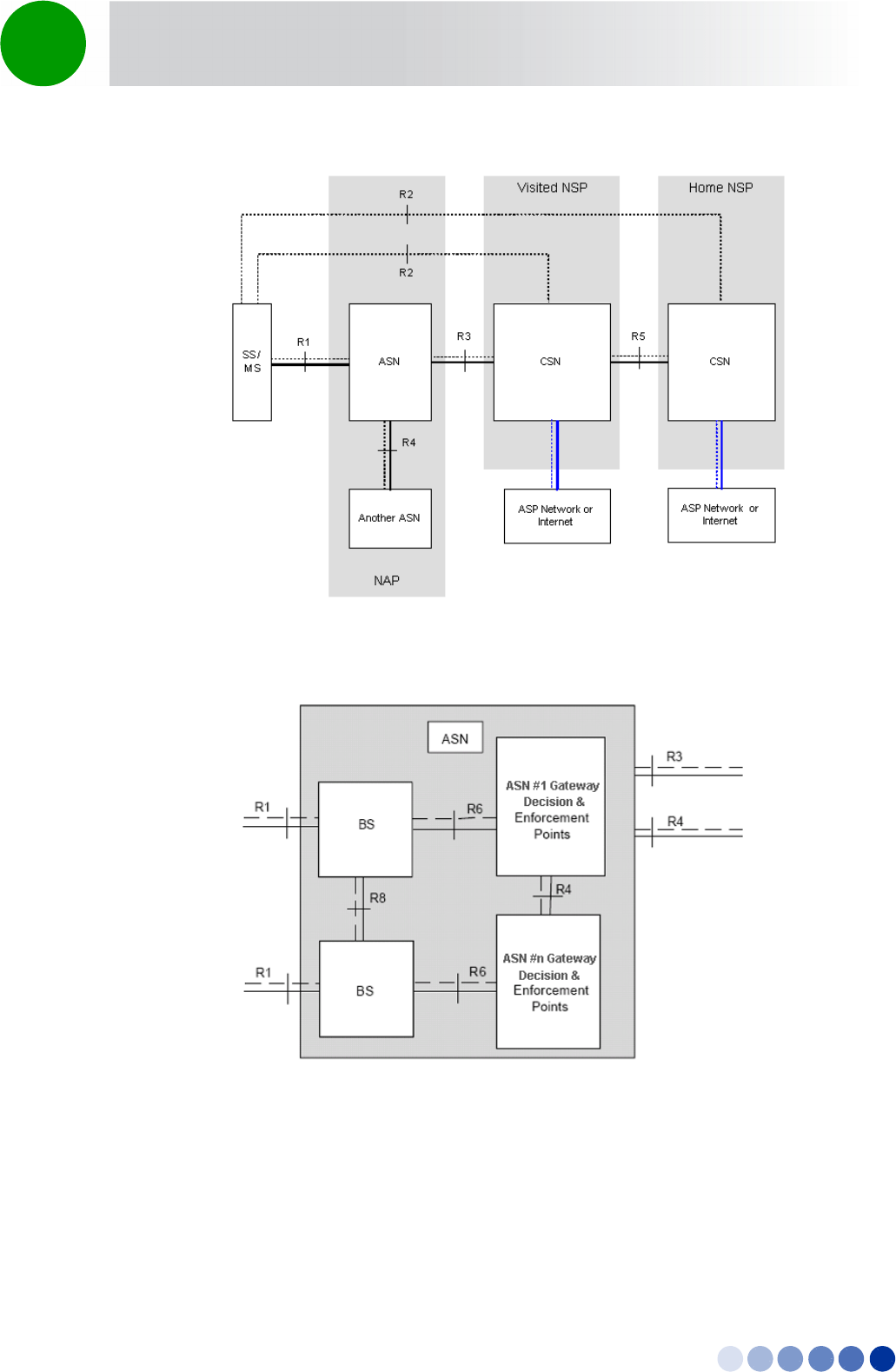
1.1.2 WiMAX Network Reference Model
Figure 1-1 and Figure 1-2 show the basic mobile WiMAX network architecture, with a single ASN-GW
and with multiple ASN-GWs, as defined by the WiMAX Forum NWG
BreezeCOMPACT System Manual 3
Chapter 1 - System Description About WiMAX
.
The various components and entities involved in the networking architecture are:
1.1.2.1 Access Service Network (ASN)
An ASN is defined as a complete set of network functions needed to provide radio access to a WiMAX
subscriber. The ASN provides the following mandatory functions:
Figure 1-1: Mobile WiMAX Network Reference Model
Figure 1-2: ASN Reference Model containing Multiple ASN-GWs

BreezeCOMPACT System Manual 4
Chapter 1 - System Description About WiMAX
WiMAX Layer-2 (L2) connectivity with WiMAX mobile station (MS)
Transfer of AAA messages to the WiMAX subscriber's home network service provider (H-NSP) for
authentication, authorization and session accounting for subscriber sessions
Network discovery and selection of the WiMAX subscriber's preferred NSP
Relay functionality for establishing Layer-3 (L3) connectivity with a WiMAX MS (i.e. IP address
allocation)
Radio resource management
ASN-CSN tunneling
ASN anchored mobility
An ASN is comprised of network elements such as one or more base transceiver stations and one or
more ASN gateways. An ASN may be shared by more than one connectivity service network (CSN).
1.1.2.2 Connectivity Service Network (CSN)
A CSN is defined as a set of network functions that provide IP connectivity services to WiMAX
subscribers. A CSN may offer the following functions:
MS IP address and endpoint parameter allocation for user sessions
Internet access
AAA proxy or server
Policy and admission control based on user subscription profiles
ASN-CSN tunneling support
WiMAX subscriber billing and inter-operator settlement
WiMAX services such as location-based services, connectivity for peer-to-peer services, provisioning,
authorization and/or connectivity to IP multimedia services, and facilities to support lawful intercept
services such as those compliant with Communications Assistance Law Enforcement Act (CALEA)
procedures
A CSN is comprised of network elements such as routers, proxy/servers, user databases, and
inter-working gateway devices.
1.1.2.3 Network Access Provider (NAP)
An NAP is a business entity that provides WiMAX radio access infrastructure to one or more WiMAX
network service providers (NSPs). A NAP implements this infrastructure using one or more ASNs.
1.1.2.4 Network Service Provider (NSP)
An NSP is a business entity that provides IP connectivity and WiMAX services to WiMAX subscribers
compliant with the established service level agreement. The NSP concept is an extension of the Internet
service provider (ISP) concept, providing network services beyond Internet access. To provide these

BreezeCOMPACT System Manual 5
Chapter 1 - System Description About WiMAX
services, an NSP establishes contractual agreements with one or more NAPs. An NSP may also establish
roaming agreements with other NSPs and contractual agreements with third-party application providers
(e.g. ASP, ISP) for the delivery of WiMAX services to subscribers. From a WiMAX subscriber standpoint,
an NSP may be classified as a home or visited NSP.
1.1.2.5 Base Station (BS)
The WiMAX BS is an entity that implements the WiMAX MAC and PHY in compliance with the IEEE
802.16e standard. A BS operates on one frequency assignment, and incorporates scheduler functions
for uplink and downlink resources.
The basic functionality of the BS includes:
IEEE 802.16e OFDMA PHY/MAC entity
R6 and R8 functionality according to NWG definitions
Extensible Authentication Protocol (EAP) relay
Control message authentication
User traffic authentication and encryption
Handover management
QoS service flow management entity
1.1.2.6 ASN Gateway (ASN-GW)
The ASN-GW is a network entity that acts as a gateway between the ASN and CSN. The ASN functions
hosted in an ASN-GW may be viewed as consisting of two groups - the decision point (DP) and
enforcement point (EP). The EP includes bearer plane functions, and the DP includes non-bearer plane
functions.
The basic DP functionality of the ASN-GW includes:
Implementation of EAP Authenticator and AAA client
Termination of RADIUS protocol against the selected CSN AAA server (home or visited AAA server) for
MS authentication and per-MS policy profile retrieval
Storage of the MS policy profile
Generation of authentication key material
QoS service flow authorization entity
AAA accounting client
The basic EP functionality of the ASN-GW includes:
Classification of downlink data into generic routing encapsulation (GRE) tunnels
Packet header suppression functionality
BreezeCOMPACT System Manual 6
Chapter 1 - System Description About WiMAX
DHCP functionality
Handover functionality
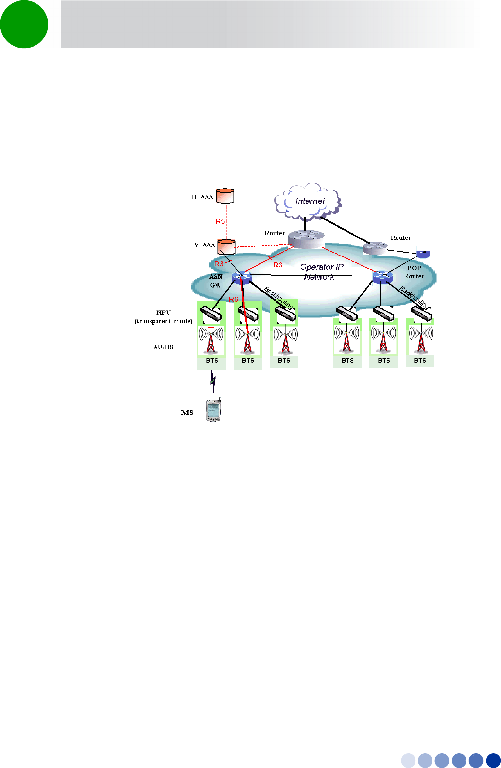
The WIMAX Forum NWG has adopted two different approaches for ASN architecture - centralized and
distributed: In the centralized approach there is at least one central ASN-GW, and the BTS operates in
transparent mode, as shown in Figure 1-3.
Figure 1-3: Centralized Network Reference Model
BreezeCOMPACT System Manual 7
Chapter 1 - System Description About WiMAX
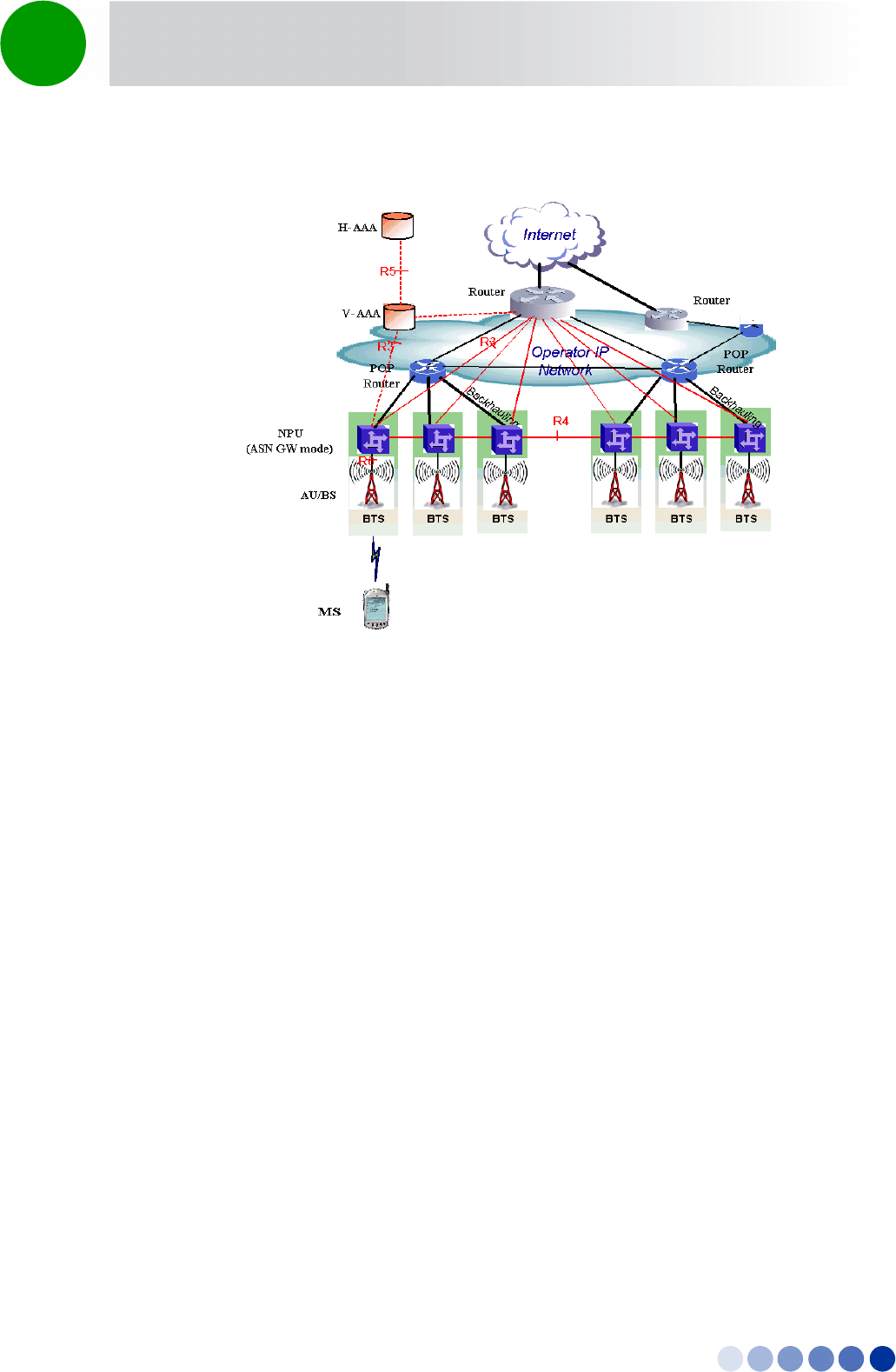
In the distributed approach, the BTS operates in ASN-GW mode, as shown in Figure 1-4.
Alvarion believes in providing operators with the flexibility to select the mobile WiMAX network
topology that best suits their needs and existing network architecture. Therefore, 4Motion is designed to
support both distributed and centralized topology approaches according to WiMAX Forum NWG profile
C.
1.1.2.7 Reference Points
Reference point R1 consists of the protocols and procedures between the MS and ASN as per the
air-interface (PHY and MAC) specifications (IEEE 802.16e).
Reference point R2 consists of protocols and procedures between the MS and CSN associated with
authentication, services authorization and IP host configuration management. This reference point is
logical in that it does not reflect a direct protocol interface between the MS and CSN. The
authentication part of reference point R2 runs between the MS and CSN operated by the home NSP,
however, the ASN and CSN operated by the visited NSP may partially process the aforementioned
procedures and mechanisms. Reference point R2 might support IP host configuration management
running between the MS and CSN (operated by either the home NSP or visited NSP).
Reference point R3 consists of the set of control plane protocols between the ASN and CSN to
support AAA, policy enforcement and mobility management capabilities. It also encompasses the
bearer plane methods (e.g. tunneling) to transfer user data between the ASN and CSN.
Reference point R4 consists of the set of control and bearer plane protocols originating/terminating
in various functional entities of an ASN that coordinate MS mobility between ASNs and ASN-GWs. R4
is the only interoperable reference point between similar or heterogeneous ASNs.
Figure 1-4: Distributed Network Reference Model

BreezeCOMPACT System Manual 8
Chapter 1 - System Description About WiMAX
Reference point R5 consists of the set of control plane and bearer plane protocols for
internetworking between the CSN operated by the home NSP and that operated by a visited NSP.
Reference point R6 consists of the set of control and bearer plane protocols for communication
between the BS and ASN-GW. The bearer plane consists of an intra-ASN data path between the BS
and ASN gateway. The control plane includes protocols for data path establishment, modification and
release control in accordance with the MS mobility events.
Reference point R8 consists of the set of control plane message flows and optional bearer plane
data flows between the base stations to ensure a fast and seamless handover. The bearer plane
consists of protocols that allow data transfer between base stations involved in the handover of a
certain MS.
It is important to note that all reference points are logical and do not necessarily imply a physical or even
direct connection. For instance, the R4 reference point between ASN-GWs might be implemented across
the NAP internal transport IP network, in which case R4 traffic might traverse several routers from the
source to the destination ASN-GW.

BreezeCOMPACT System Manual 9
Chapter 1 - System Description The BreezeCOMPACT Solution
1.2 The BreezeCOMPACT Solution
1.2.1 BreezeCOMPACT Highlights
BreezeCOMPACT is a small, lightweight, all-outdoor single box base transceiver station enabling easy
installation and maintenance and reduced Total Cost of Ownership (TCO).
BreezeCOMPACT enhances Alvarion's 4Motion product portfolio of BreezeMAX Macro and Micro BTS
systems with a compact all-outdoor 4x4 platform enabling extended and flexible installation capabilities
while sustaining 4Motion leading technological advantages and ecosystem.
BreezeCOMPACT is a weatherized carrier-class WiMAX 802.16e platform, based on Software Defined
Radio (SDR) that is SW upgradable for new technologies such as Time-Division Long-Term Evolution
(TD-LTE) and IEEE 802.16m. It is an integral part of 4Motion end-to-end solution. BreezeCOMPACT BTS
complements Alvarion's Macro BTS products for coverage and capacity extension as well as rural
deployment scenarios.
BreezeCOMPACT is a reliable platform utilizing the mature field-proven 4Motion modules and
ecosystem elements (e.g. ASN-GW, AAA, and WiMAX™ devices), hence delivering high product
availability.
Portable and mobile subscribers can connect to BreezeCOMPACT base station through various end-user
terminals such as USB dongles, Self Installed (SI) Residential Gateways (RGW), and Outdoor CPEs.
Alvarion's Compact, Micro and Macro solutions share similar functionality with same ecosystem,
allowing flexible mix & match approach to address various operator deployment needs.
Alvarion believes that compliance with standard-driven open architecture protects the infrastructure
investment, and opens the system to a variety of fully interoperable end-user devices. As such, 4Motion
is designed with open architecture and interfaces according to the WiMAX Forum networking working
group (NWG) profile C, which supports openness and enables flat as well as hierarchical topologies. In
addition, by keeping the radio resource management functionality in the Base Transceiver Station only,
Profile C delivers a faster, optimized handover mechanism.
1.2.2 Network Architectures
BreezeCOMPACT supports different network architectures:
External ASN-GW
Embedded ASN-GW Local Authentication
Embedded ASN-GW Centralized Authentication
INFORMATION
In the current release only External ASN-GW network architecture is supported.

BreezeCOMPACT System Manual 10
Chapter 1 - System Description The BreezeCOMPACT Solution
Following is a description of each of these working modes:
1.2.2.1 External ASN-GW
The ASN-GW is a separate entity (centralized architecture) that communicates with the BTS over R6
interface. Service components (Service Profiles and Service Flows) are configured in the external
ASN-GW. MS authentication and services provisioning are managed by a centralized AAA server, based
on user credentials (user name and password).
1.2.2.2 Embedded ASN-GW Local Authentication
The ASN-GW functionality resides in the BTS (distributed architecture). Service components (Service
Profiles and Service Flows) are configured in the internal ASN-GW of each BTS. MSs list and services
provisioning including authentication are managed locally by the internal ASN-GW (AAA server not
needed), based on the SU MAC address.
1.2.2.3 Embedded ASN-GW Centralized Authentication
The ASN-GW functionality resides in the BTS (distributed architecture). Service components (Service
Profiles and Service Flows) are configured locally in the BTS. MS authentication and service provisioning
are managed centrally by an external AAA server, based on user credentials (user name and password).
1.2.3 System Topologies
BreezeCOMPACT supports different system topologies:
One Sector, One Carrier
One Sector, Dual Carrier
Two Sector, Two Carriers (One Carrier per Sector)
Following is a description of each of these topologies:
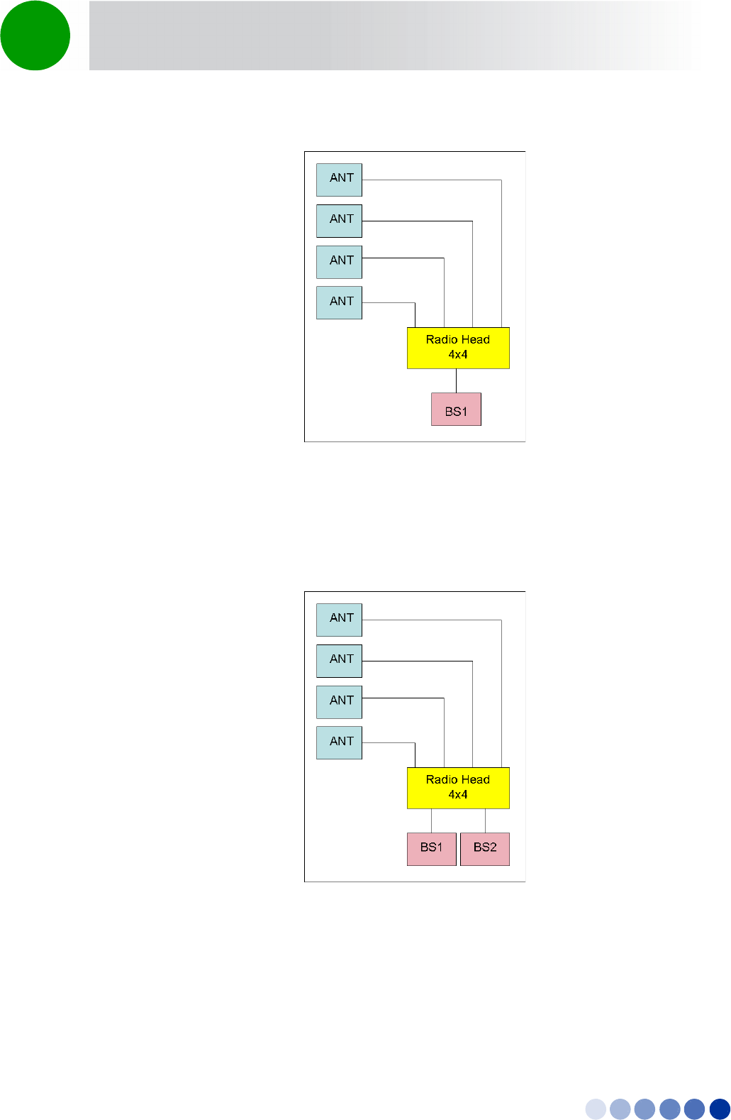
1.2.3.1 One Sector, One Carrier
This is the basic configuration based on a single BS, supporting a single 4x4 sector with a bandwidth of
5, 7, or 10 MHz.
INFORMATION
In the current release only One Sector, One Carrier topology with a 10 MHz bandwidth is supported.
BreezeCOMPACT System Manual 11
Chapter 1 - System Description The BreezeCOMPACT Solution
1.2.3.2 One Sector, Dual Carrier
Two BSs support a single 4x4 sector with a total bandwidth of 20 (10+10) or 14 (7+7) MHz.
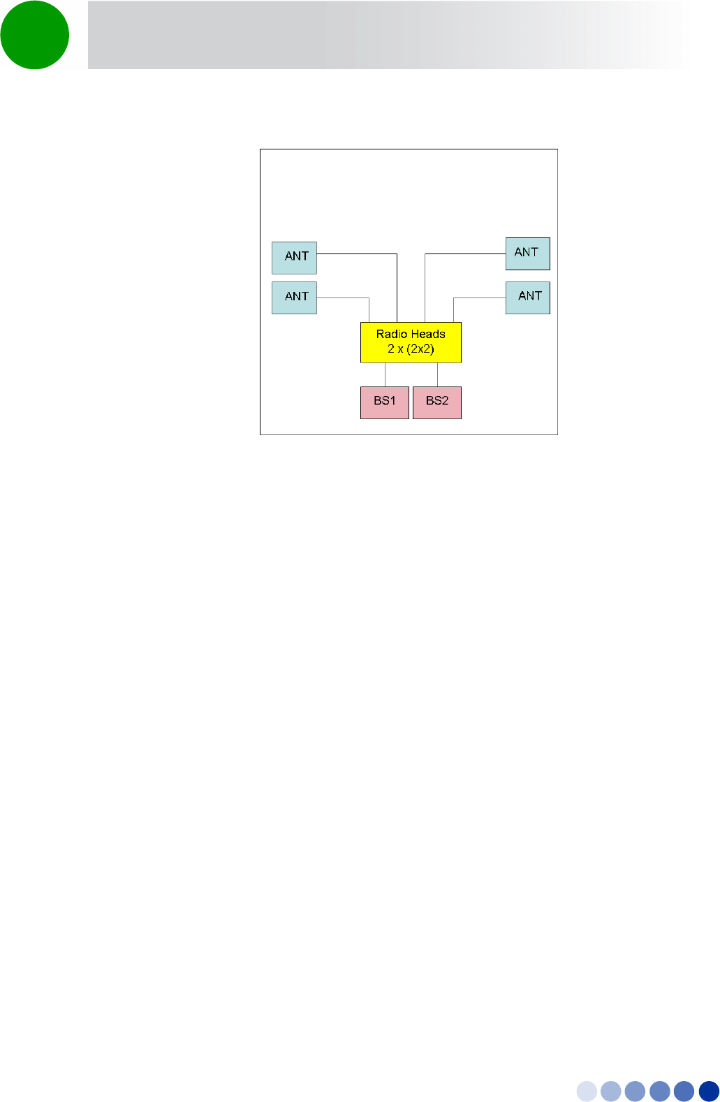
1.2.3.3 Two Sector, Two Carriers (One Carrier per Sector)
Two BSs support two 2x2 sectors, each with a bandwidth of 10 or 7 MHz.
Figure 1-5: One Sector, One Carrier
Figure 1-6: One Sector, Dual Carrier
BreezeCOMPACT System Manual 12
Chapter 1 - System Description The BreezeCOMPACT Solution
1.2.4 Antennas
In the 4Motion architecture, the antenna is approached as an independent element. This provides the
operator with the flexibility to select the antennas source according to its supplier policy. To ensure the
availability of antennas that complement the 4Motion solution, Alvarion works closely with several
antenna suppliers to ensure availability of antennas that comply with its requirements.
In cases where the operator prefers other antenna vendors, Alvarion can provide a recommended
antenna specification based on the required antennas types.
Antennas may support one or several different downtilt options:
Mechanical Down-Tilt (MDT) using a suitable mounting kit.
Electrical Down-Tilt (EDT) that may be either fixed or adjustable using a special adjustment screw.
Remote Electrical Tilt (RET) through a special interface.
Alvarion offers also AISG (Antenna Interface Standards Group) compliant electrical downtilt control kit
enabling remote tilt control for antennas that support RET.
In addition to a range of standard commercial antennas, Alvarion offers also a special attached antenna
design for convenient installation on top of the BreezeCOMPACT unit.
For details on antennas offered by Alvarion refer to “Antennas” on page 19.
Figure 1-7: Two Sectors, Two Carriers (One Carrier per Sector)

BreezeCOMPACT System Manual 13
Chapter 1 - System Description The BreezeCOMPACT Solution
1.2.5 GPS
GPS is used to synchronize the air link frames of Intra-site and Inter-site located Base Transceiver Stations
to ensure that in all Base Stations the air frame will start at the same time, and that all Base Stations will
switch from transmit (downlink) to receive (uplink) at the same time. This synchronization is necessary to
prevent Intra-site and Inter-site interference and Base Stations saturation (assuming that all Base Stations
are operating with the same frame size and with the same DL/UL ratio).
In order for the system to be synchronized, the GPS have to first acquire at least 4 satellites. After that
the GPS reception can be reduced to 1 satellite. If no satellite is received the BTS will go to holdover state
where internal clock is provided to synchronize the BTS for up to two hours. Following a pre-configured
time in holdover state the unit will stop transmissions to avoid interfering with the operation of
neighboring units.
The all-outdoor GPS Receiver is a pole mountable GPS receiver and antenna in a single environmentally
protected enclosure. The receiver is powered from the unit, and it can be installed at a distance of up to
100m from the unit. GPS signals chaining (not supported in current release) enables using a single GPS
receiver for several colocated units.

BreezeCOMPACT System Manual 14
Chapter 1 - System Description Element Management Systems
1.3 Element Management Systems
The end-to-end IP-based architecture of the system enables full management of all components, using
standard management tools. An SNMP agent in the NPU implements proprietary MIBs for remote setting
of operational modes and parameters of the Base Transceiver Station equipment. Security features
incorporated in the equipment restrict the access for management purposes.
Alvarion offers the following management tool:
1.3.1 AlvariSTAR
AlvariSTAR is a comprehensive carrier-class Element Management System (EMS) for Alvarion’s Broadband
Wireless Access systems. AlvariSTAR is designed for today's most advanced Network Operation Centers
(NOCs), providing the network Operation, Administration and Maintenance (OA&M) staff and managers
with all the network surveillance, monitoring and configuration and service provisioning capabilities
required to effectively manage the network while keeping the resources and expenses at a minimum.
AlvariSTAR offers the network's OA&M staff with a unified, scalable and distributable management
system. Utilizing distributed client-server architecture, the user is provided with a robust, scalable and
fully redundant management system in which all single points of failure can be avoided.
AlvariSTAR provides the following management functionality:
Device Discovery
Device Inventory
Topology
Fault Management
Configuration Management
Service Management
Data Collection
Performance Monitoring
Device embedded software upgrade
Template-based configuration modification of multiple BTS simultaneously.
Preparation of offline configuration files for mass configuration of new BTSs.
Security Management
Event Forwarding to other Network Management Systems.

BreezeCOMPACT System Manual 15
Chapter 1 - System Description Specifications
1.4 Specifications
1.4.1 Modem & Radio
Table 1-1: General Modem & Radio Specifications
Item Description
Frequency Band 3400-3675
Central Frequency Resolution 0.125 MHz
Operation Mode TDD
Channel Bandwidth 5 MHz
7 MHz
10 MHz
Bandwidth Support Up to 20 MHz
Ports Configuration 4x4
Maximum Tx Power 27 dBm per channel
Tx Power Control Range 10 dB, in 1 dB steps
Tx Power Accuracy +/- 1 dB
Maximum Input Power @
antenna port
-45 dBm before saturation, -35 dBm before damage
Noise Figure 5 dB typical, 6 dB maximum
Modulation OFDM modulation, 1024/512 FFT points; QPSK, QAM16, QAM64
Access Method OFDMA
FEC Convolutional Turbo Coding:
1/2, 3/4 for QPSK and QAM16.
1/2, 2/3, 3/4, 5/6 for QAM64

BreezeCOMPACT System Manual 16
Chapter 1 - System Description Specifications
1.4.2 Sensitivity (per channel)*
* For second order receive diversity configurations sensitivity is improved by 3 dB. For fourth order
receive diversity configurations sensitivity is improved by 6 dB.
1.4.3 Data Communication (Ethernet Interfaces)
Table 1-2: Per Channel Sensitivity, AWGN @ PER=1%
Modulation & Coding Sensitivity (dBm),
5 MHz Bandwidth
Sensitivity (dBm),
7 MHz Bandwidth
Sensitivity (dBm),
10 MHz Bandwidth
QPSK 1/2 Repetition 6 -102 -100 -99
QPSK 1/2 Repletion 4 -101 -99 -98
QPSK 1/2 Repletion 2 -99 -97 -96
QPSK 1/2 -96 -94 -93
QPSK 3/4 -93 -91 -90
16QAM 1/2 -90 -88 -87
16QAM 3/4 -85 -83 -82
64QAM1/2 -84 -82 -81
64QAM2/3 -82 -79 -78
64QAM3/4 -80 -78 -77
64QAM5/6 -78 -76 -75
Table 1-3: Data Communication (Ethernet Interfaces)
Item Description
Standard Compliance IEEE 802.3 CSMA/CD
DAT 1 (optional, if an SFP is installed) 100/1000 Mbps Base-X optical fiber interface, Full Duplex
with Auto Negotiation.
DAT 2 100/1000 Mbps Base-T twisted-pair electrical interface,
Half/Full Duplex with Auto Negotiation.
DAT 3 10/100 Mbps Base-T twisted-pair electrical interface, Half/Full
Duplex with Auto Negotiation.

BreezeCOMPACT System Manual 17
Chapter 1 - System Description Specifications
1.4.4 Configuration and Management
1.4.5 Standards Compliance, General
1.4.6 Environmental
Table 1-4: Configuration and Management
Item Description
Management (Out Of Band, In Band) SNMP
Telnet
SNMP Agents SNMP Ver. 2 client
MIB II (RFC 1213), Private MIBs
Software Upgrade Using TFTP
Configuration Upload/Download Using TFTP
Table 1-5: Standards Compliance, General
Typ e Standard
EMC ETSI EN 301 489-1/4
FCC Part 15
Safety EN60950-1 (CE)
UL 60950-1 (US/C)
Environmental ETS 300 019:
Part 2-1 T 1.2 & part 2-2 T 2.3 for indoor & outdoor
Part 2-3 T 3.2 for indoor
Part 2-4 T 4.1E for outdoor
Radio ETSI EN 302 326
FCC Part 90 Subpart Z
IC RSS-192 issue1
IC RSS-197 issue 3
Table 1-6: Environmental Specifications
Typ e Details
Operating Temperature -40°C to 55°C
Operating Humidity 5%-95%, weather protected

BreezeCOMPACT System Manual 18
Chapter 1 - System Description Specifications
1.4.7 Mechanical and Electrical
Table 1-7: Mechanical & Electrical Specifications
Item Description
Dimensions 242.7 x 343 x 166.9 mm
Weight 9 Kg
Power Source -40 to -60 VDC
Power Consumption 125 W peak
PoE Out (DAT 3) 1 A @ -40 to -60 VDC

BreezeCOMPACT System Manual 19
Chapter 1 - System Description Specifications
1.4.8 Antennas
1.4.8.1 Attached, 3.3-3.8 GHz, 4 Ports 65º Double Dual Slant (xx)
Table 1-8: Attached Antenna 3.3-3.8 DDS 65º (P.N. 300726) Specifications
Item Description
Frequency Band (MHz) 3300-3800
Number of Elements 4
Polarization Linear, +/-45°
Gain (dB) 18
Azimuth Beamwidth (degrees) 65
Elevation Beamwidth (degrees) 6.5
Maximum Power (W) 150
Cross-polarization Discrimination (dB) >15
Front-to-Back Ratio (dB) >30
Electrical Downtilt Range (degrees) 0
Isolation Between Ports (dB) >30
Return Loss (dB) >15
RF Interface Impedance (Ohm) 50
RF Connectors 4 x N-Type jacks with RF cable tails
Dimensions (mm) 720x 266 x 52
Weight (Kg) 4
Regulatory Compliance RoHS Compliance

BreezeCOMPACT System Manual 20
Chapter 1 - System Description Specifications
1.4.8.2 3.3 -3.8 GHz, 4 Ports 65º Double Dual Slant (xx), with EDT
Table 1-9: ANT BS-EDT-DDP-65°-3.3-3.8GHz (P.N. 323109) Specifications
Item Description
Frequency Band (MHz) 3300-3800
Number of Elements 4
Polarization Linear, 2 x +/-45°
Gain (dB) 18
Azimuth Beamwidth (degrees) 65
Elevation Beamwidth (degrees) 6.5° with nullfill
Elevation Side Lobe Level (dB) <-18
Maximum Power (W) 150
Front-to-Back Ratio (dB) >30
Electrical Downtilt Range 0° - 10° independently continuously adjustable
Isolation Between Ports (dB) >30
Return Loss (dB) >15
RF Interface Impedance (Ohm) 50
RF Connectors 4 x N-Type jack
Mounting F-042-GL-E: Fixed clamps for 50-115 mm
diameter pipe, 5Kg
T-045-GL-E: Adjustable clamps for 50-115 mm
diameter pipe, 0-10° down tilt, 6Kg
Dimensions (mm) 750 x 300 x 115
Weight (Kg) 10

BreezeCOMPACT System Manual 21
Chapter 1 - System Description Specifications
1.4.8.3 3.3 -3.8 GHz, 2 Ports 65º Dual Slant (x)
Table 1-10: ANT,BS,3.3-3.8GHz, DS,Sec.65°,16.5dBi min (P.N. 300644) Specifications
Item Description
Frequency Band (MHz) 3300-3800
Number of Elements 2
Polarization Linear, +/-45°
Gain 16.5dBi +/- 0.5dB
VSWR 1.5:1 (max)
Azimuth Beamwidth (degrees) 65 +/-5
Elevation Beamwidth (degrees) 6 +/-1
Maximum Power (W) 50
Cross-polarization Discrimination (dB) -15
Front-to-Back Ratio (dB) >25
Isolation Between Ports (dB) >25
RF Interface Impedance (Ohm) 50
Lightning Protection DC grounded
RF Connectors 2 x N-Type jacks
Mounting Fully adjustable pipe mount (1.63” to 4.5” pipe)
with 0-15° down tilt
Dimensions (mm) 711 x 171 x 90
Weight (Kg) 2.6 (excluding mounting kit)
Regulatory Compliance RoHS Compliance

BreezeCOMPACT System Manual 22
Chapter 1 - System Description Specifications
1.4.8.4 3.3 -3.8 GHz, 2 Ports 90º Dual Slant (x)
Table 1-11: ANT,BS,3.3-3.8GHz, DS,Sec.90°,15.5dBi min (P.N. 300645) Specifications
Item Description
Frequency Band (MHz) 3300-3800
Number of Elements 2
Polarization Linear, +/-45°
Gain 15.5dBi +/- 0.5dB
VSWR 1.5:1 (max)
Azimuth Beamwidth (degrees) 85 +/-5
Elevation Beamwidth (degrees) 6 +/-1
Maximum Power (W) 50
Cross-polarization Discrimination (dB) -17
Front-to-Back Ratio (dB) >25
Isolation Between Ports (dB) >25
RF Interface Impedance (Ohm) 50
Lightning Protection DC grounded
RF Connectors 2 x N-Type jacks
Mounting Fully adjustable pipe mount (1.63” to 4.5” pipe)
with 0-15° down tilt
Dimensions (mm) 711 x 171 x 90
Weight (Kg) 2.6 (excluding mounting kit)
Regulatory Compliance RoHS Compliance

BreezeCOMPACT System Manual 23
Chapter 1 - System Description Specifications
1.4.8.5 3.3 -3.8 GHz, 4 Ports 65º Double Dual Slant (xx)
Table 1-12: ANT-DDP-65°-3.3-3.8GHz (P.N. 300720) Specifications
Item Description
Frequency Band (MHz) 3300-3800
Number of Elements 4
Polarization Linear, 2 x +/-45°
Gain 18dBi
Azimuth Beamwidth (degrees) 65
Elevation Beamwidth (degrees) 7
Maximum Power (W) 150
Cross-polarization Discrimination (dB) >15
Front-to-Back Ratio (dB) >30
Isolation Between Ports (dB) >30
Return Loss (dB) >15
Upper Sidelobe Suppression (dB) >18
RF Interface Impedance (Ohm) 50
Lightning Protection DC grounded
RF Connectors 4 x N-Type jack
Electrical Downtilt 4° (fixed)
Mounting Adjustable mounting kit (optional) for 50-115mm
pole, with +2° to -10° tilt range
Dimensions (mm) 720 x 260 x 55
Weight (Kg) 7 (excluding mounting kit)

BreezeCOMPACT System Manual 24
Chapter 1 - System Description Specifications
1.4.8.6 3.3 -3.8 GHz, 4 Ports 90º Double Dual Slant (xx)
Table 1-13: ANT-DDP-90°-3.3-3.8GHz (P.N. 300719) Specifications
Item Description
Frequency Band (MHz) 3300-3800
Number of Elements 4
Polarization Linear, 2 x +/-45°
Gain 17dBi
Azimuth Beamwidth (degrees) 90
Elevation Beamwidth (degrees) 7
Maximum Power (W) 150
Cross-polarization Discrimination (dB) >15
Front-to-Back Ratio (dB) >30
Isolation Between Ports (dB) >30
Return Loss (dB) >15
Upper Sidelobe Suppression (dB) >18
RF Interface Impedance (Ohm) 50
Lightning Protection DC grounded
RF Connectors 4 x N-Type jack
Electrical Downtilt 4° (fixed)
Mounting Adjustable mounting kit (optional) for 50-115mm
pole, with +2° to -10° tilt range
Dimensions (mm) 720 x 260 x 55
Weight (Kg) 7 (excluding mounting kit)

BreezeCOMPACT System Manual 25
Chapter 1 - System Description Specifications
1.4.8.7 3.3 -3.8 GHz, 90º Vertical
Table 1-14: ANT BS 3.3-3.8GHz, 90° V (P.N. 300616) Specifications
Item Description
Frequency Band (MHz) 3300-3800
Number of Elements 1
Polarization Vertical
Gain 14.5dBi (min)
VSWR 1.8:1 (max)
Azimuth Beamwidth (degrees) 90
Elevation Beamwidth (degrees) 7
Maximum Power (W) 10
RF Interface Impedance (Ohm) 50
Lightning Protection DC grounded
RF Connectors 2 x N-Type jacks
Mounting Tilt Mounting Kit for 2” to 4.5” Dia pole
Dimensions (mm) 766 x 150 x 86
Weight (Kg) 2.2 (excluding mounting kit)
Regulatory Compliance ESTI EN 302 085 V.1.1.2 (2001-02) CS3
RoHS Compliance

BreezeCOMPACT System Manual 26
Chapter 1 - System Description Specifications
1.4.9 BMAX-4M-GPS Receiver Specifications
Table 1-15: BMAX-4M-GPS Receiver, Mechanical & Electrical Specifications
Item Description
Dimensions 8.8 x 10.4 x 16 cm
Weight 0.38 Kg
Power Source 12 VDC from the NPU
Power Consumption 2W maximum
Connector RJ-45

Chapter 2 - BreezeCOMPACT
Installation
In this Chapter:
“Introduction” on page 28
“Unpacking and Inspecting” on page 29
“BreezeCOMPACT Installation” on page 35
“Connecting the BreezeCOMPACT Cables” on page 53
“System Initial Verification” on page 68
“GPS Installation” on page 47

4Motion Installation Manual 28
Chapter 2 - BreezeCOMPACT Installation Introduction
2.1 Introduction
BreezeCOMPACT is a small, lightweight, optimized single box, all-outdoor base station system enabling
easy installation and maintenance, thus reducing the operator's Total Cost of Ownership (TCO).
BreezeCOMPACT allows flexible mounting options including rooftops, walls, poles and top towers
installation, thus providing an effective solution for installation-constrained areas.
CAUTION
ONLY experienced installation professionals who are familiar with local building and safety codes and,
wherever applicable, are licensed by the appropriate government regulatory authorities should install
outdoor units and antennas.
Failure to do so may void the product warranty and may expose the end user or Service Provider to
legal and financial liabilities. Alvarion and its resellers or distributors are not liable for injury, damage or
regulation violations associated with the installation of Outdoor Units or antennas.
Français
SEULS les installateurs professionnels expérimentés qui sont familiers avec les codes locaux des
bâtiments et de la sécurité et, lorsque cela s'applique, qui sont autorisés par les autorités
gouvernementales de régulation, doivent installer les unités extérieures et les antennes. Le non-respect
de cette clause peut invalider la garantie du produit et exposer l'utilisateur final ou le prestataire de
services à des responsabilités légales et financières. Le fabricant et ses revendeurs ou distributeurs ne
sont pas responsables pour toute blessure, dommage ou violation de la réglementation associée à
l'installation d'unités extérieures ou d'antennes.
Italiano
ATTENZIONE: SOLO professionisti esperti che hanno familiarità con le norme di costruzione locali e coi
codici di sicurezza e, ove applicabile, sono autorizzati dalle autorità governative competenti possono
installare unità esterne ed antenne. Assicurarsi che le unità esterne, antenne e strutture di supporto
siano installate correttamente per eliminare ogni pericolo fisico a persone o cose. In caso contrario, ciò
può invalidare la garanzia del prodotto e può esporre l'utente finale o il fornitore di servizi a
responsabilità legali ed economiche. Anche quando la messa a terra non è obbligatoria in base alla
normativa regolatoria applicabile e ai codici nazionali, è obbligatorio garantire che l'unità esterna e il
palo dell'antenna siano messi a terra e idonei dispositivi di protezione contro i fulmini siano utilizzati in
modo da fornire protezione contro le sovratensioni e le scariche statiche. In ogni caso, il Fornitore e i
suoi rivenditori non sono responsabili per eventuali danni fisici, danni ad oggetti o violazioni del
regolamento associati con o causati dall' installazione, la messa a terra o di protezione contro i fulmini.

4Motion Installation Manual 29
Chapter 2 - BreezeCOMPACT Installation Unpacking and Inspecting
2.2 Unpacking and Inspecting
1Examine the shipping container for damage. If you notice any damage, notify the carrier that
delivered the unit immediately and enter a service call in Alvarion's SSM (www.alvarion.com >
Customer Service area).
2Check the items against this manual. If any items are missing, notify your agent immediately.
3Remove the packing material without damaging it.
4Components susceptible to damage from static electricity are packed in static resistant bags. Unpack
these items in a static-free environment to avoid damage.
4Motion Installation Manual 30
Chapter 2 - BreezeCOMPACT Installation Unpacking and Inspecting
2.2.1 Package Content
BTS (weight: 9 kg)
Mounting kit (for 1''-4'' poles) including:
»4 x heavy duty metal clamps
»4 x M8 threaded rods
»4 x M8x22 Hex screws
»8 x M8 nuts
»8 x M8 flat washers
»8 x M8 spring washers
Sealing gland wrench
For poles up to 6'' - an additional kit containing 4 metal bands (ordered separately)
For poles larger than 6” and for wall mount - two large heavy duty metal clamps (ordered separately)
2.2.2 Additional Installation Requirements
The following items are also required to install the BTS:
Power Supply: High power AC/DC Power Supply unit and DC power cable* (available in various
lengths)
Power cable*: a 250m power cable drum. 6-pin mini-fit (manufactured by Samtek), DC in -40 to
-60VDC at connector input.
Ethernet cable*: a 250m CAT5e cable drum (connectors not included)
Optical fiber cable*: 10/100/1000BASE-T Optic SFP (small form-factor pluggable) shielded
Antenna(s)* and RF cable(s)* for connecting the antenna(s) to the BTS. (applicable for units without
integral antennas). External antennas are connected via LMR-400 1m / 0.5m cables.
Grounding 10 AWG cable with an appropriate termination
GPS Antenna kit including mounting kit, 3m cable, and one lightning arrestor
Hook for carrying the assembly up the pole
Installation tools and materials
INFORMATION
Items marked with an asterisk (*) are available from Alvarion.