Alvarion Technologies COMPACT3X Base station transceiver User Manual Compact System Manual
Alvarion Technologies Ltd. Base station transceiver Compact System Manual
Contents
- 1. User manual, part 1
- 2. User manual, part 2
- 3. User manual
- 4. Response_FCC_22854_June-17-2012
User manual, part 2

4Motion Installation Manual 31
Chapter 2 - BreezeCOMPACT Installation Unpacking and Inspecting
For wall mount installation - four suitable dowels and screws
Complementary products:
»Maintenance Cabinet - required for backup batteries, power system, AC/DC power adaptors and
local transport/backhauling equipment
»Auxiliary Box - required for Dry Contact alarms, connectivity controllers, and easy access to
technical support
2.2.3 Mounting Options
Use the following table as a reference for installation depending on your system configuration.
Book Title Installation Manual 32
Chapter 2 - BreezeCOMPACT Installation Unpacking and Inspecting
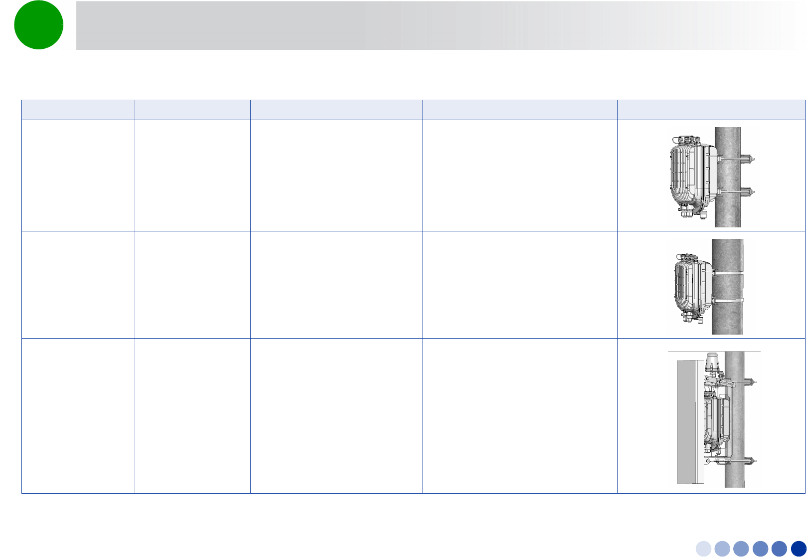
Table 2-1: Mounting Options
Configuration Option Use kit Refer to Example
Standalone (without an
attached antenna)
Pole mount - poles
between 1” - 4”
Pole mount kit (four clamps),
supplied with the unit
“To mount the BTS on a pole of up to 4”
(using clamps):” on page 36
Pole mount - poles up
to 6”
Metal bands
Pole mount kit (two clamps only)
“To mount the BTS on a pole of up to
6”(using metal bands):” on page 37
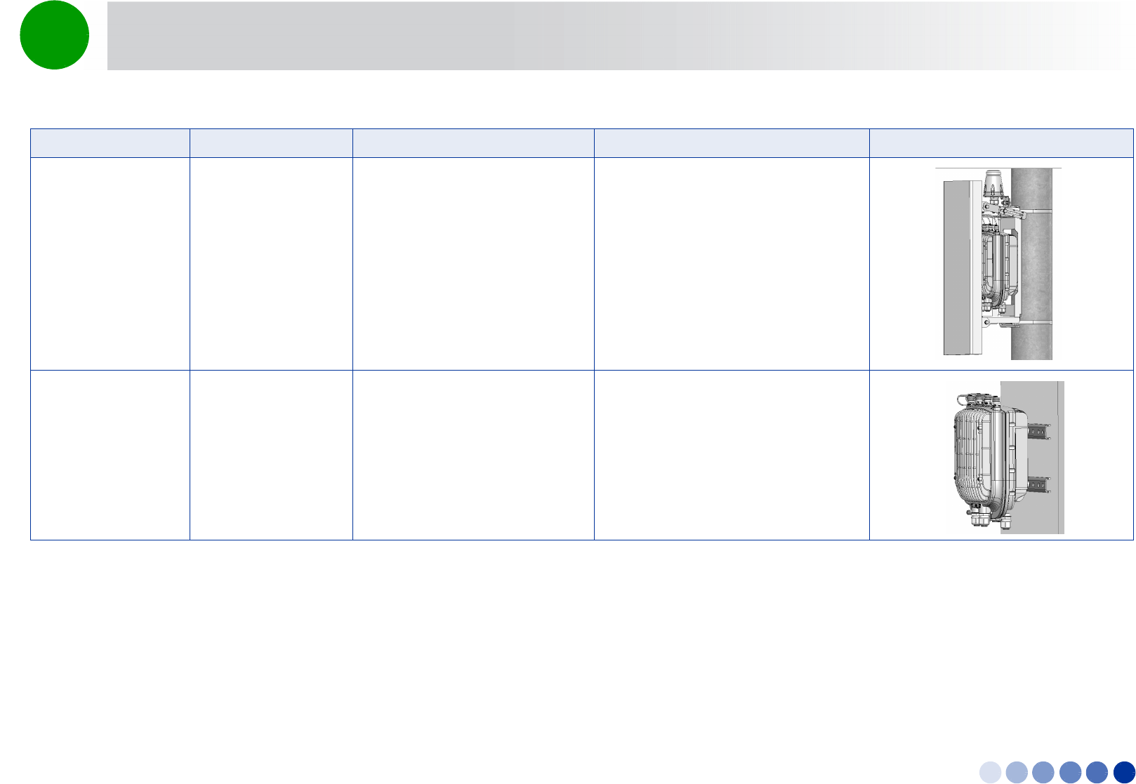
With an attached
antenna
Pole mount - poles
between 1” - 4”
Antenna
Pole mount kit
Antenna mounting kit (includes
carriage and parts to attach the
antenna)
“Pole Mounting with an Attached
Antenna” on page 39
“To prepare for mounting on a 1”-4”
pole:” on page 40
“To mount the antenna:” on page 43
Book Title Installation Manual 33
Chapter 2 - BreezeCOMPACT Installation Unpacking and Inspecting
With an attached
antenna
Pole mount - poles up
to 6”
Pole mount kit (supplied with the
unit)
Metal bands
Antenna
Antenna mounting kit (includes
carriage and parts to attach the
antenna)
1“To prepare for mounting on a pole up
to 6'' (using metal bands):” on page 43
2“To mount the antenna:” on page 43
Standalone Wall mount Wall mount kit “Wall Mount Installation” on page 45
Table 2-1: Mounting Options
Configuration Option Use kit Refer to Example
Book Title Installation Manual 34
Chapter 2 - BreezeCOMPACT Installation Unpacking and Inspecting
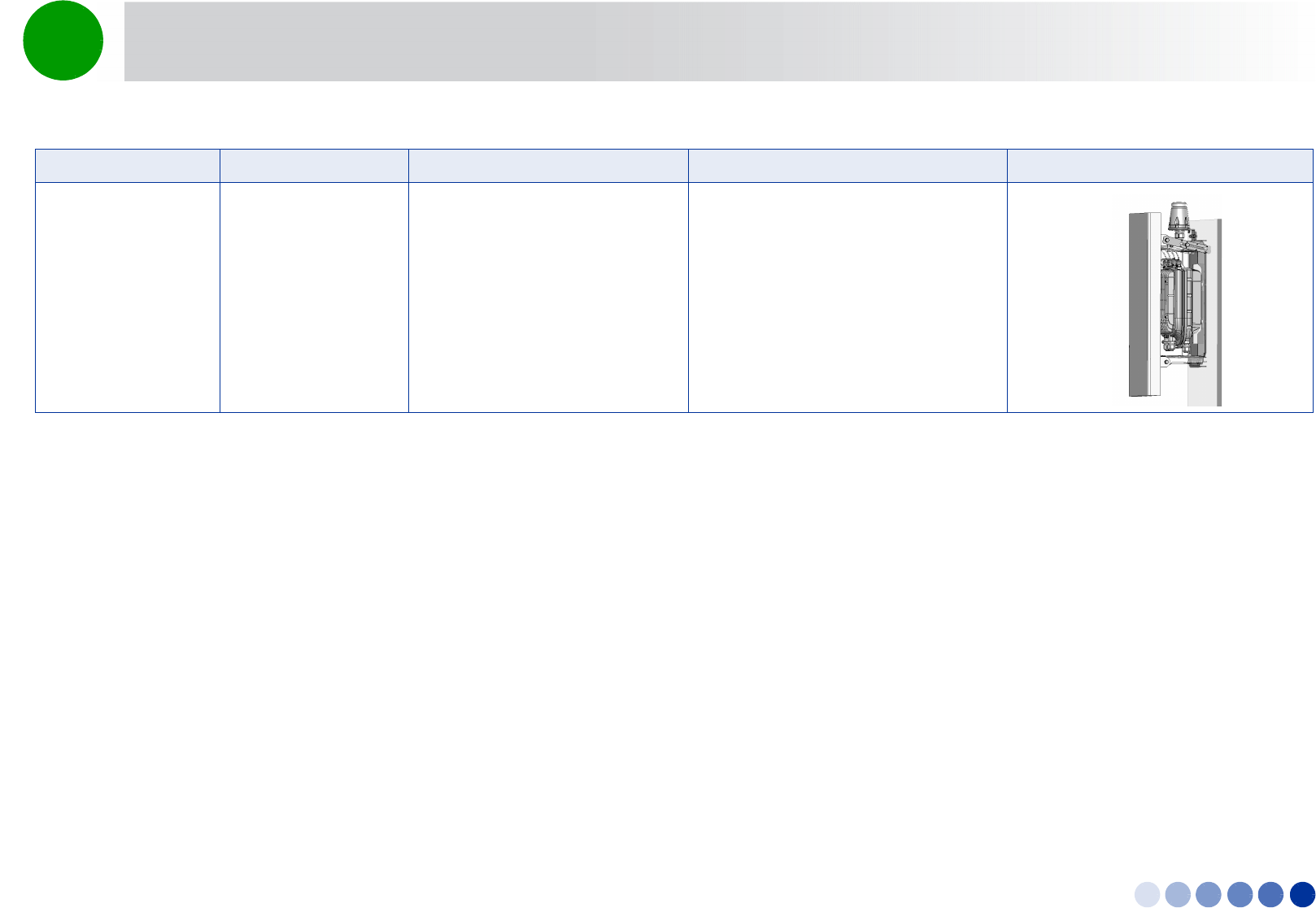
With an attached
antenna
Wall mount Antenna
Antenna mounting kit (includes
carriage and parts to attach the
antenna)
Wall mount kit
1“To mount the antenna:” on page 43
2“Wall Mount Installation” on page 45
Table 2-1: Mounting Options
Configuration Option Use kit Refer to Example
4Motion Installation Manual 35
Chapter 2 - BreezeCOMPACT Installation BreezeCOMPACT Installation
2.3 BreezeCOMPACT Installation
2.3.1 Installing the BTS on a Pole
The BTS can be installed on poles of various sizes using the supplied mounting kits.
For poles of 1''-4'' in diameter, use the supplied metal clamps.
For larger poles (up to 6”) use the metal bands and two clamps out of the four included in the pole
mount kit.
When an attached antenna is to be installed together with the BTS, use the carriage mounting kit, which
includes a carriage and parts to attach the antenna. Install the BTS and the antenna on the ground and
then lift the assembly up the pole using the carrying hook.
INFORMATION
Install the unit with the bottom panel, including the LEDs, facing downward. Note the direction arrows
(UP) on the sides of the BTS.
CAUTION
The weight of the BTS is 9 kg and the weight of the Pole Mounting Kit is approximately 5 kg. Make sure
to plan the installation accordingly. It is recommended to use a harness and carrying hook to lift the
units.
Install the unit using the supplied kit only.
CAUTION
Do not use the hook for lifting the assembly when the GPS is installed on the carriage. This may damage
the GPS. Tie the carriage on both sides and carefully lift it up the pole.
4Motion Installation Manual 36
Chapter 2 - BreezeCOMPACT Installation Pole Mounting without an Attached Antenna (Standalone)
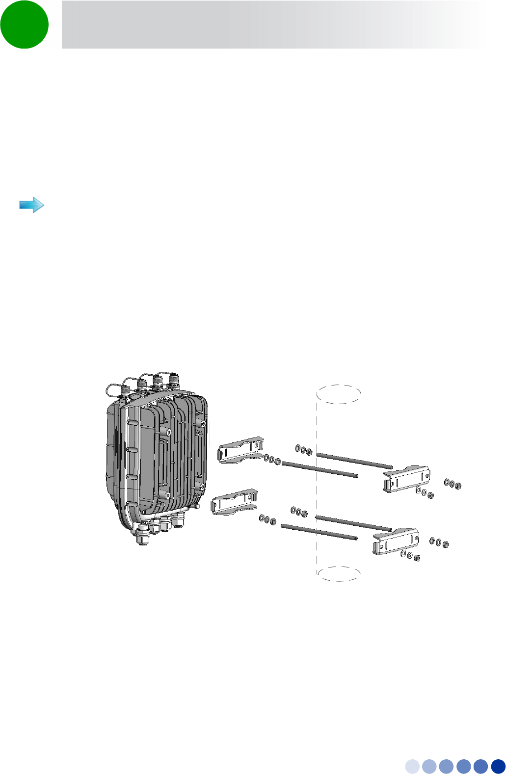
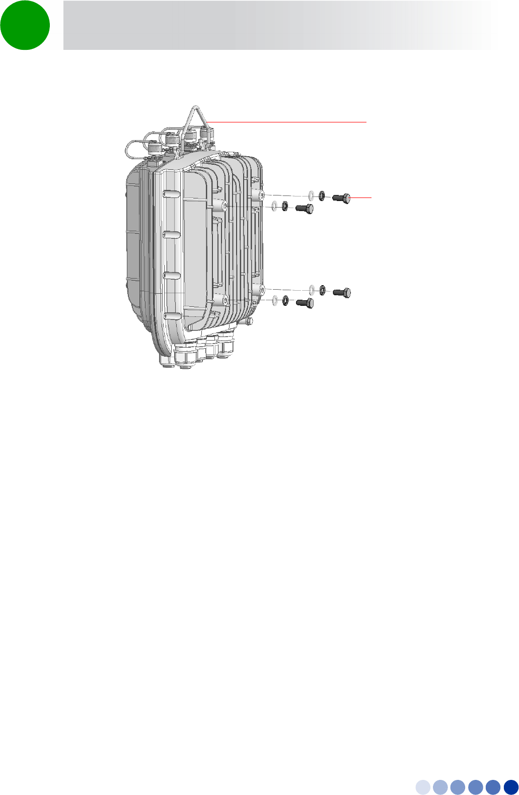
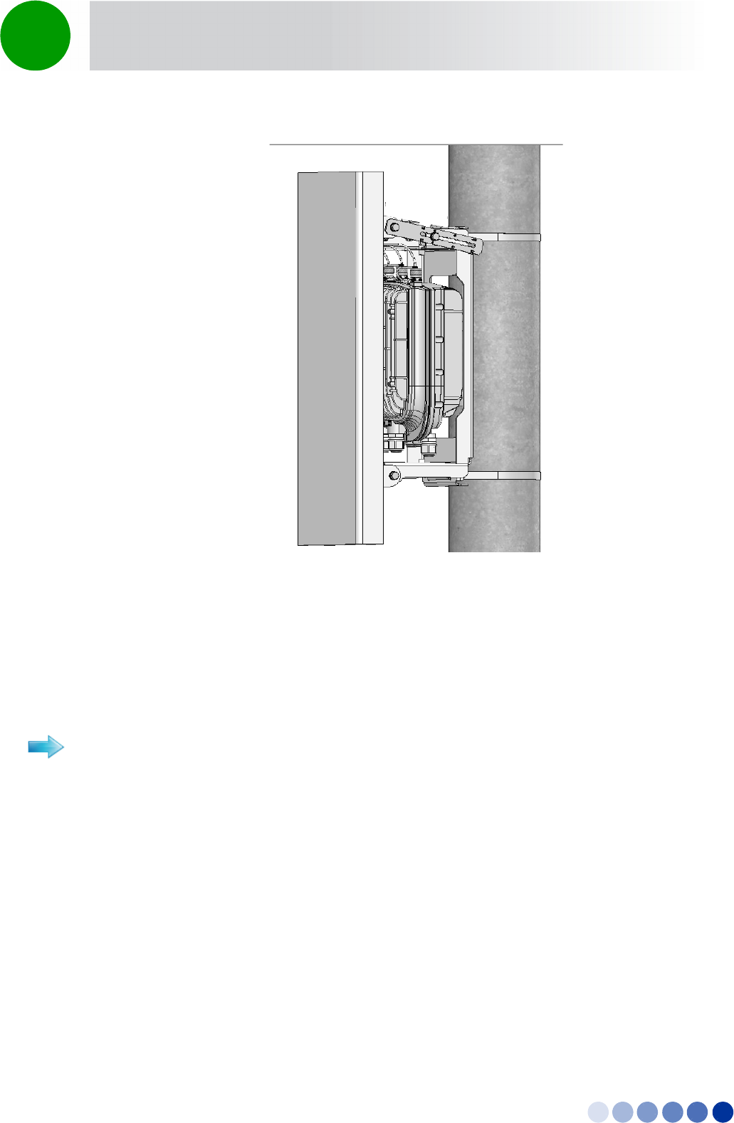
2.4 Pole Mounting without an Attached Antenna
(Standalone)
When not using the attached antenna, mount the BTS on the pole using the pole mount kit supplied
with the BTS.
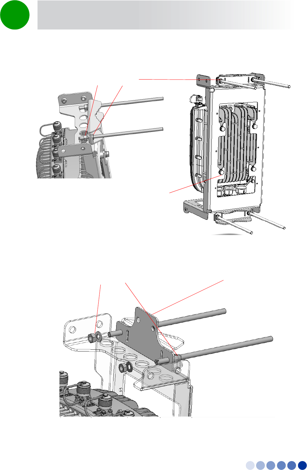
Refer to Figure 2-1 and Figure 2-2.
1Thread the four rods through the nuts, washers, spring washers, and two clamps, and fasten the
clamps to the BTS mounting holes.
2Attach the BTS with the mounted clamps to the pole.
3Thread the other two clamps to the rods and use the nuts washers and spring washers to fasten and
fix the BTS to the pole.
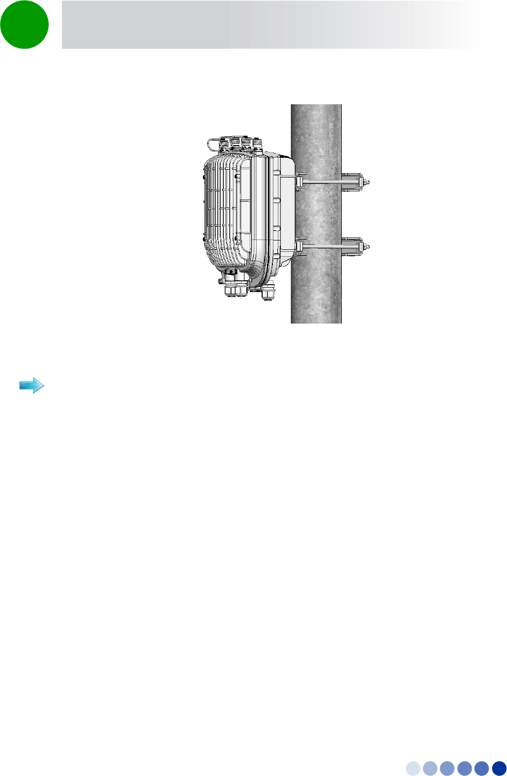
To mount the BTS on a pole of up to 4” (using clamps):
Figure 2-1: Pole Mounting without the Carriage
4Motion Installation Manual 37
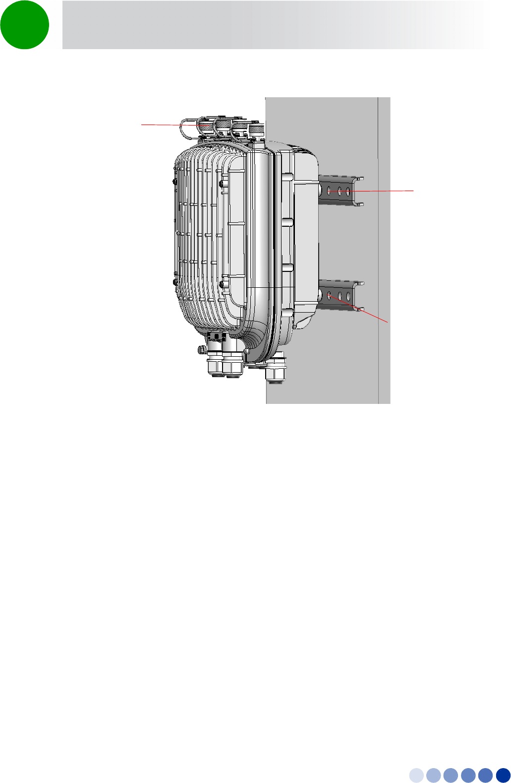
Chapter 2 - BreezeCOMPACT Installation Pole Mounting without an Attached Antenna (Standalone)
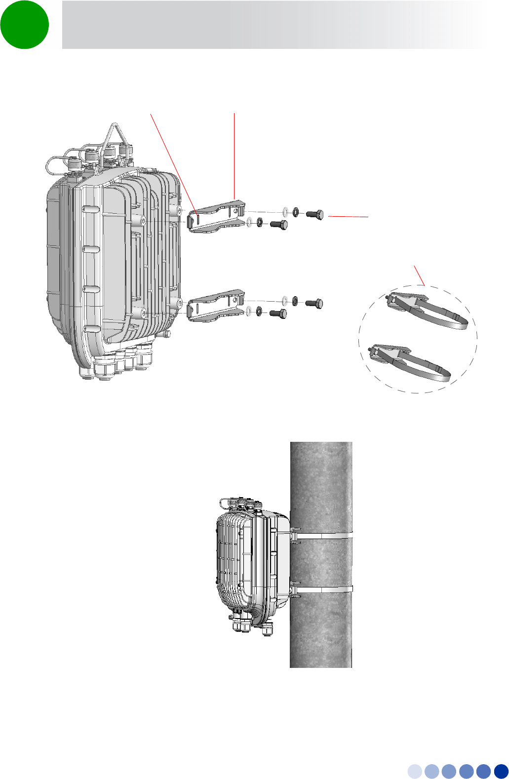
Refer to Figure 2-3 and Figure 2-4.
1Thread two metal bands through the designated grooves in two clamps.
2Attach the clamps to the BTS and use the screws, washers and spring washers to fasten the clamps to
the BTS (Figure 2-3)
3Close and fasten the bands.
Figure 2-2: BTS Installed on the Pole
To mount the BTS on a pole of up to 6”(using metal bands):
4Motion Installation Manual 38
Chapter 2 - BreezeCOMPACT Installation Pole Mounting without an Attached Antenna (Standalone)
Figure 2-3: Attaching the Clamps
Figure 2-4: BTS Installed on Poles Using Metal Bands
Clamps
Screws, Washers
and Spring Washers
Grooves for Metal Bands
Metal Bands on
Clamps

4Motion Installation Manual 39
Chapter 2 - BreezeCOMPACT Installation Pole Mounting with an Attached Antenna
2.5 Pole Mounting with an Attached Antenna
When using the attached antenna, you first mount the BTS on the carriage, then also the antenna (and
optionally GPS), and finally lift the assembly up the pole, attach the clamps/metal bands and fasten the
screws.
2.5.1 Package Content
Antenna
Antenna mounting kit, including:
»One carriage
»2 x Antenna tilting arms
»6 x M8 Hex nuts
»6 x M8x22 screws
»6 x M8 flat washers
»6 x M8 spring washers
Pole mount kit - use the following parts:
»Clamps/metal bands depending on pole diameter
»4 rods
»8 x nuts, washers, and spring washers
Hook for carrying the assembly up the pole
TBD Describe single sector installation including Double Dual Slant attached antenna with the RF cable
tails.
TBDAlso describe 2 sectors installation with 2 separate Dual Slant antennas located in space diversity of
1.3m with additional RF cables 1m/0.5m.
4Motion Installation Manual 40
Chapter 2 - BreezeCOMPACT Installation Pole Mounting with an Attached Antenna
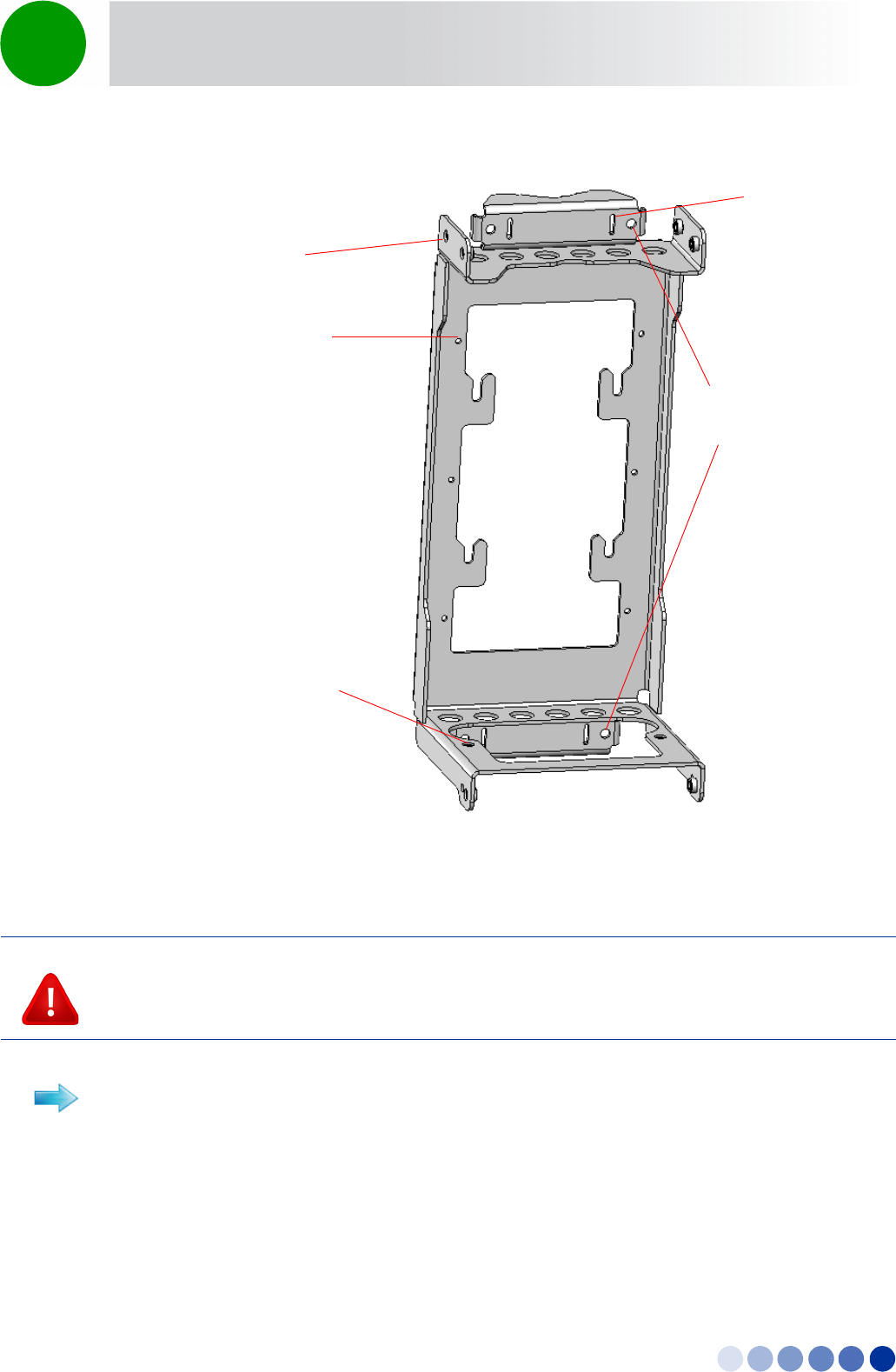
2.5.2 Mounting the BTS and Antenna on the Carriage
1Attach the M8x20 nuts, washers and spring washers to the BTS and slightly fasten.
Figure 2-5: The Carriage, Part of the Antenna Mounting Kit
CAUTION
The weight of BTS is 9 Kg and the weight of the Pole Mounting Kit is approximately 5 kg. Plan the
installation accordingly. It is recommended to use a harness to lift the units.
Install the unit using the supplied kit only.
To prepare for mounting on a 1”-4” pole:
Holes for pole
mounting rods (x4)
Grooves for
metal bands
Holes for fastening
screws (x6)
Holes for external
antenna kit screws (x2)
Holes for external
antenna kit
screws (x4)
4Motion Installation Manual 41
Chapter 2 - BreezeCOMPACT Installation Pole Mounting with an Attached Antenna
2Hang the BTS screws on the BTS carriage hanging hooks. Locate the carriage hooks between the
washers and the BTS.
3Insert the four threaded rods through the holes in the carriage. If you intend to mount the GPS on the
carriage, thread the rods through the GPS bracket as well (Refer to “To install the GPS on the
carriage:” on page 48’ and Figure 2-8).
4Attach nuts, washers and spring washers to both sides of the threaded rods and fasten to fix the rods
in place on the carriage (Figure 2-7).
Figure 2-6: Preparing the BTS for Installation
M8x20 nuts, washers
and spring washers
Carrying hook
4Motion Installation Manual 42
Chapter 2 - BreezeCOMPACT Installation Pole Mounting with an Attached Antenna
Figure 2-7: BTS Installed on the Carriage
Figure 2-8: Installing the GPS Bracket
M8x20 nuts, washers and
spring washers on both
sides of the carriage
Hanging hooks
M8x20 nuts, washers and
spring washers on both
sides of the carriage GPS Bracket (optional)
4Motion Installation Manual 43
Chapter 2 - BreezeCOMPACT Installation Pole Mounting with an Attached Antenna
1Mount the BTS on the carriage as described in step 1-2 above.
2Thread two metal bands through the grooves on the carriage.
1Attach the antenna tilting arms to the carriage using screws, washers and spring washers. Do not
over tighten.
2Assemble the antenna and fasten the two lower screws to the carriage and the upper two to the
brackets.
To prepare for mounting on a pole up to 6'' (using metal bands):
To mount the antenna:
Figure 2-9: Assembling the Antenna on the Carriage
Antenna Tilting
Arms (x2)
Antenna Alignment
Screw (x2)
Attached Antenna
Antenna Fastening
Screws (x4)
4Motion Installation Manual 44
Chapter 2 - BreezeCOMPACT Installation Pole Mounting with an Attached Antenna
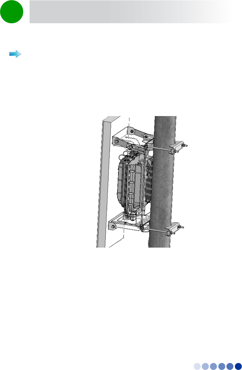
1Lift the assembly up the pole using the hook.
2For 1”-4” poles attach the other two clamps; For up to 6” poles close the metal bands and fasten.
3Fasten all the screws. Apply torques of 80 [Lib*In] = 9 [N*m] to the M8 screws.
4Tilt the antenna as necessary and fasten the alignment screws (for wall mount tilting is limited).
To mount the assembly on the pole:
Figure 2-10: BTS and Attached Antenna Mounted on a 1”-4” Pole
4Motion Installation Manual 45
Chapter 2 - BreezeCOMPACT Installation Pole Mounting with an Attached Antenna
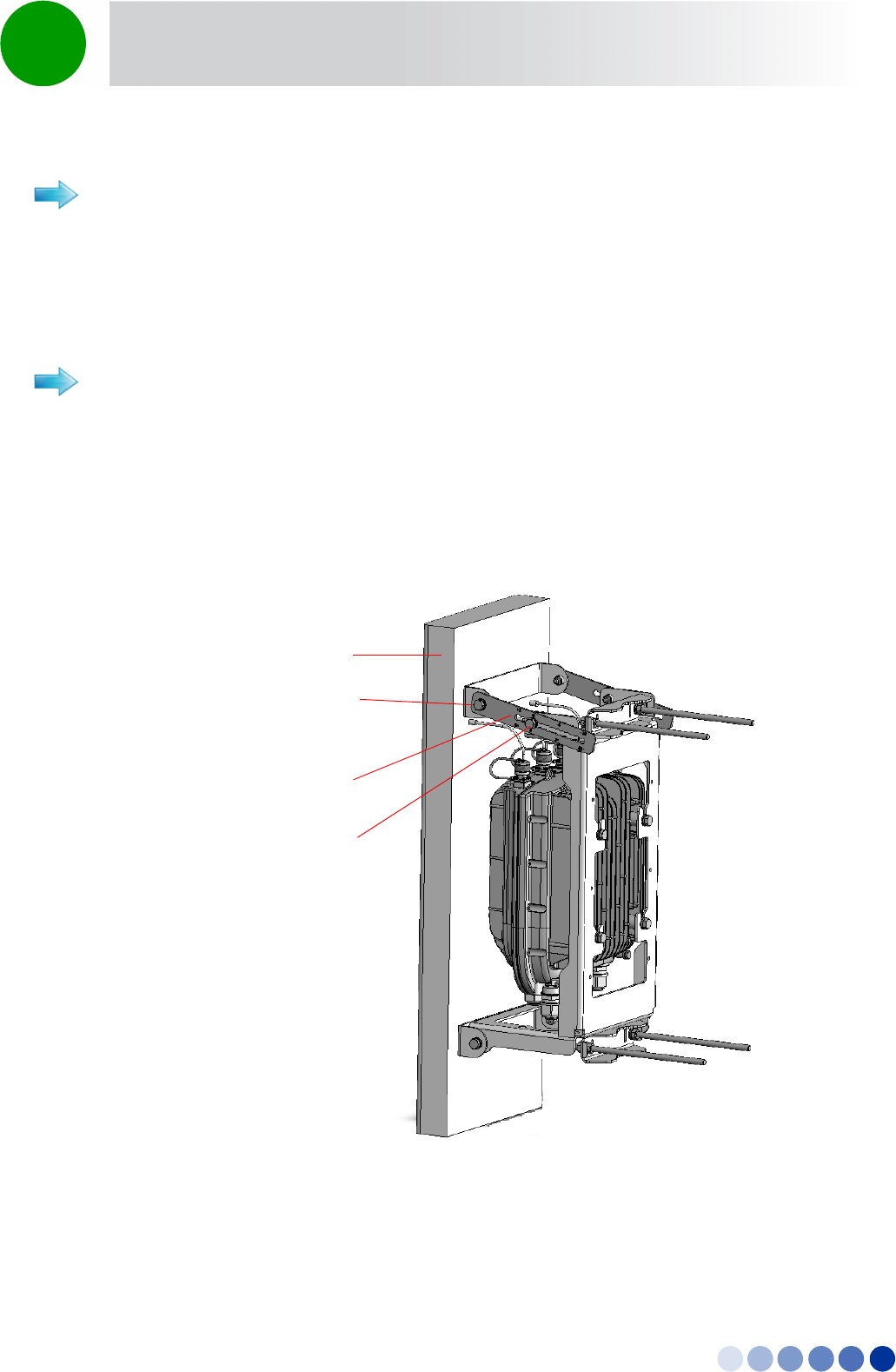
2.5.3 Wall Mount Installation
The BTS can be installed on walls. This requires attaching and fastening the carriage with the BTS to the
wall using suitable securing means (not supplied). The location of the screws should be planned with
maximum precision.
1Place the carriage on the wall and mark the exact location of the holes to drill.
2Drill the holes and use four metal dowels and screws to secure the carriage to the wall.
3Insert the tilt control screws (M8x20) into the middle-side hole of the carriage on both sides (see
Figure 2-12).
Figure 2-11: BTS and Attached Antenna Mounted Using Metal Bands
To install the BTS on a wall:
4Motion Installation Manual 46
Chapter 2 - BreezeCOMPACT Installation Pole Mounting with an Attached Antenna
4Hang the BTS on the BTS carriage hanging hooks (see “To prepare for mounting on a 1”-4” pole:” on
page 40).
5Attach and fasten all the screws.
Figure 2-12: Mounting the Carriage on the Wall
Antenna
Connections
Holes for
wall mount
Screws (to be
fastened using
dowels
4Motion Installation Manual 47
Chapter 2 - BreezeCOMPACT Installation GPS Installation
2.6 GPS Installation
GPSs are used to synchronize the air link frames of Intra-site and Inter-site located sectors to ensure that
in all sectors the air frame starts at the same time, and that all sectors switch from transmit (downlink) to
receive (uplink) at the same time. This synchronization is necessary to prevent Intra-site and Inter-site
sectors interference and saturation (assuming that all sectors are operating with the same frame size and
with the same DL/UL ratio).
Usually the GPS is installed on the top of the tower, However it can be installed on the carriage with a
special mounting kit.
Make sure to position the GPS such that there is no obstacle (buildings, antennas, chimney, large trees,
etc.) casting a shadow over the GPS antenna. The GPS antenna should have 360° open sky with no
obstacles.
2.6.1 Package Content
GPS receiver +antenna attached to a mounting bracket
Optional: Mounting kit for carriage, including
»GPS Carriage bracket
»Locking bracket
»Screws, washers, spring washers
Metal Bands (for pole mounting on poles up to 4”)
GPS Quick installation guide
2.6.2 Additional Installation Requirements
Items marked with an asterisk (*) are available from Alvarion.
Cable (IDU-ODU) - available in three lengths: 3m, 20m, 50m, 100m*. Package includes:
»Shielded Cat.5E Ethernet cable
»Two shielded RJ-45 connectors
»One RJ-45 plastic coverTBD?
A grounding cable with appropriate terminations for connecting the indoor unit's ground terminal to
the rack or to a ground connection.
CAUTION
Do not use the hook for lifting the assembly when the GPS is installed on the carriage. This may damage
the GPS. Tie the carriage on both sides and carefully lift it up the pole.
4Motion Installation Manual 48
Chapter 2 - BreezeCOMPACT Installation GPS Installation
Installation tools
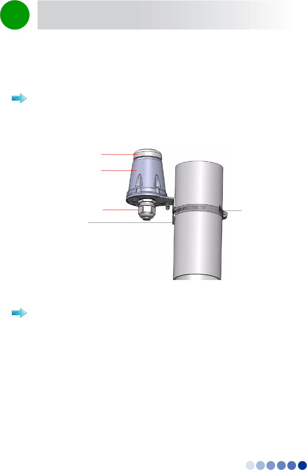
2.6.3 Installing the GPS
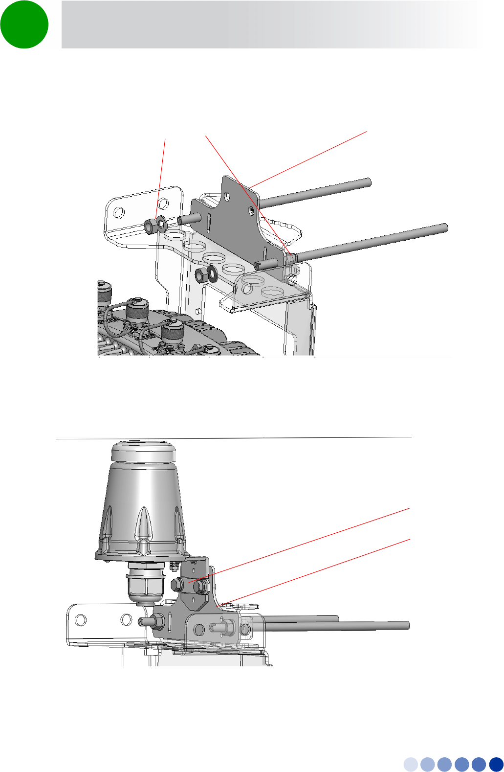
Use the metal bands to attach and fasten the GPS to a pole of up to 4” (See Figure 2-13). For
wall-mounting, thread 4mm screws (not supplied) through the designated holes and tighten firmly.
1Thread the upper two rods through the carriage and also through the GPS bracket.
2Attach nuts, washers and spring washers to both sides of the threaded rods and fasten to fix the rods
in place on the carriage (Figure 2-14).
To install the GPS on a pole:
Figure 2-13: Pole Mounting the GPS Using Metal Bands (4” Pole)
To install the GPS on the carriage:
Sealing Gland
GPS Receiver
GPS Antenna
Bracket
Metal band
4Motion Installation Manual 49
Chapter 2 - BreezeCOMPACT Installation GPS Installation
3Attach the GPS bracket to the carriage bracket, add the locking bracket and fasten the two screws.
Figure 2-14: Installing the GPS Bracket
Figure 2-15: GPS installed on the Carriage
M8x20 nuts, washers and
spring washers on both
sides of the carriage GPS Bracket (optional)
GPS Carriage
Bracket
Locking Bracket
and Screws
4Motion Installation Manual 50
Chapter 2 - BreezeCOMPACT Installation GPS Installation
2.6.4 Connecting the GPS
The Outdoor GPS Receiver is connected to the BTS via a Cat. 5E Ethernet cable. Before connecting the
cable, make sure that the length of the cable is sufficient to reach the BTS.
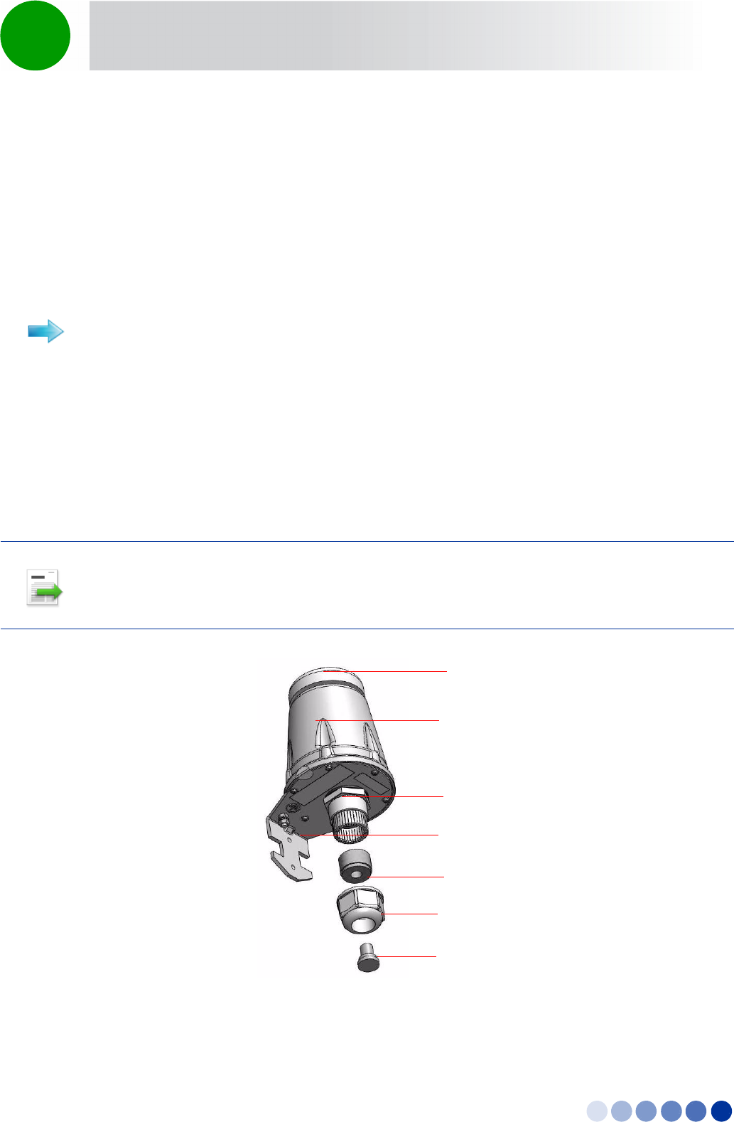
The shielded Cat.5E Ethernet cable is supplied with a rubber bushing and a sealing gland nut. During
installation, you replace the sealing gland nut and rubber bushing that are on the GPS with the same
parts that are supplied with the cable.
Refer to Figure 2-16.
1Measure the distance and make sure that the length of the cable is sufficient to reach the BTS.
2Remove the sealing gland plug from the gland nut.
3Open the sealing gland nut and remove it. Do not disassemble the gland base from the bracket.
4Remove the rubber bushing from the sealing gland.
To connect the GPS cable:
INFORMATION
The removed parts (sealing gland plug, nut and rubber bushing) can be disposed of, as they are replaced
by the same parts supplied with the GPS cable.
Figure 2-16: GPS Components
Sealing Gland Plug
Rubber Bushing
Sealing Gland Base
GPS Receiver
GPS Antenna
Bracket
Sealing Gland Nut
4Motion Installation Manual 51
Chapter 2 - BreezeCOMPACT Installation GPS Installation
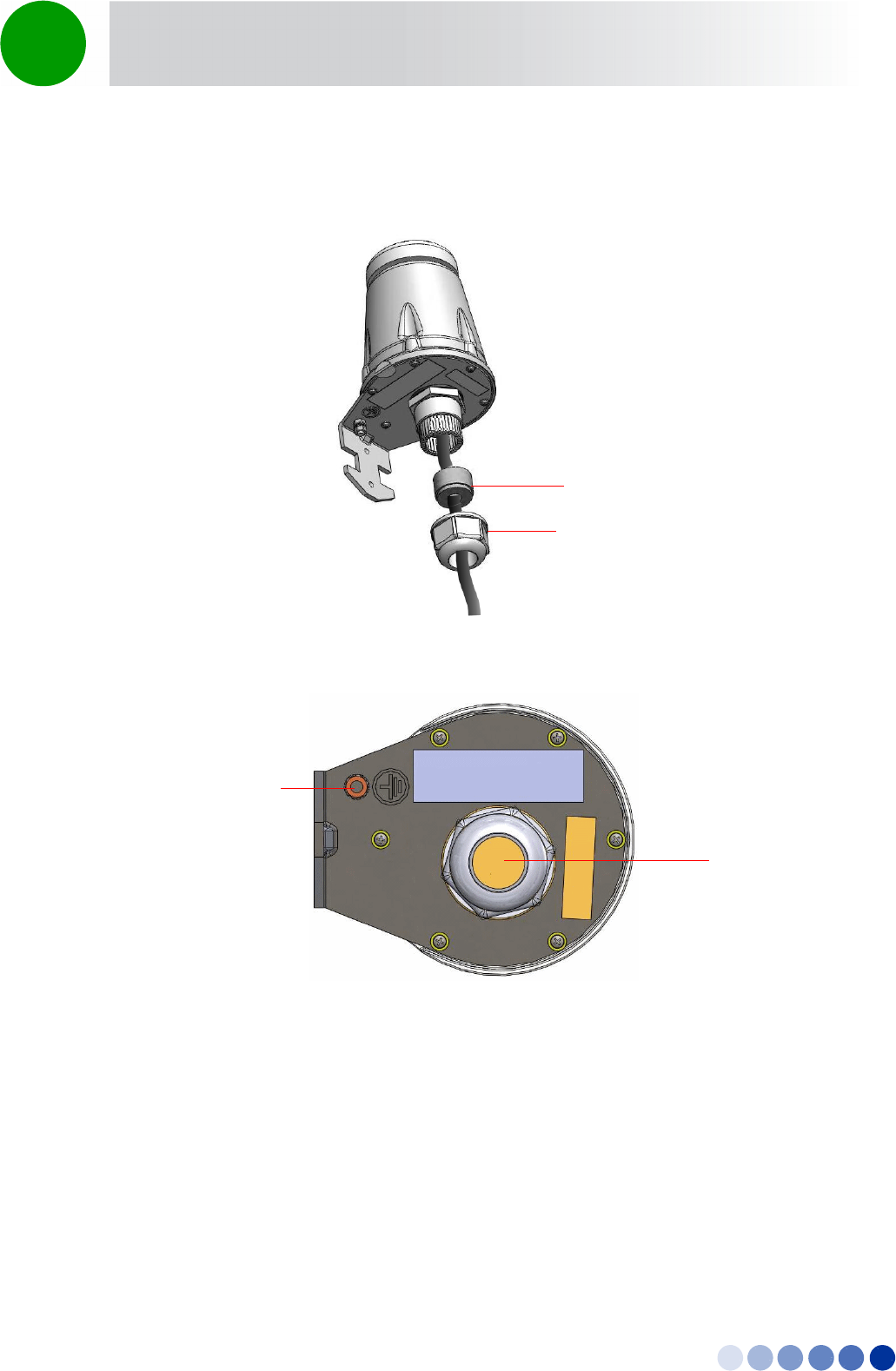
5Insert the GPS cable (side labeled GPS) into the sealing gland base (Figure 2-17) and connect it to the
RJ-45 connector at the bottom of the GPS (Figure 2-18).
6Tighten the rubber bushing on the cable inside the gland base.
7Tighten the gland nut.
8Connect the other end of the data cable to the GPS IN connector located on the BTS panel (see
Figure 2-21).
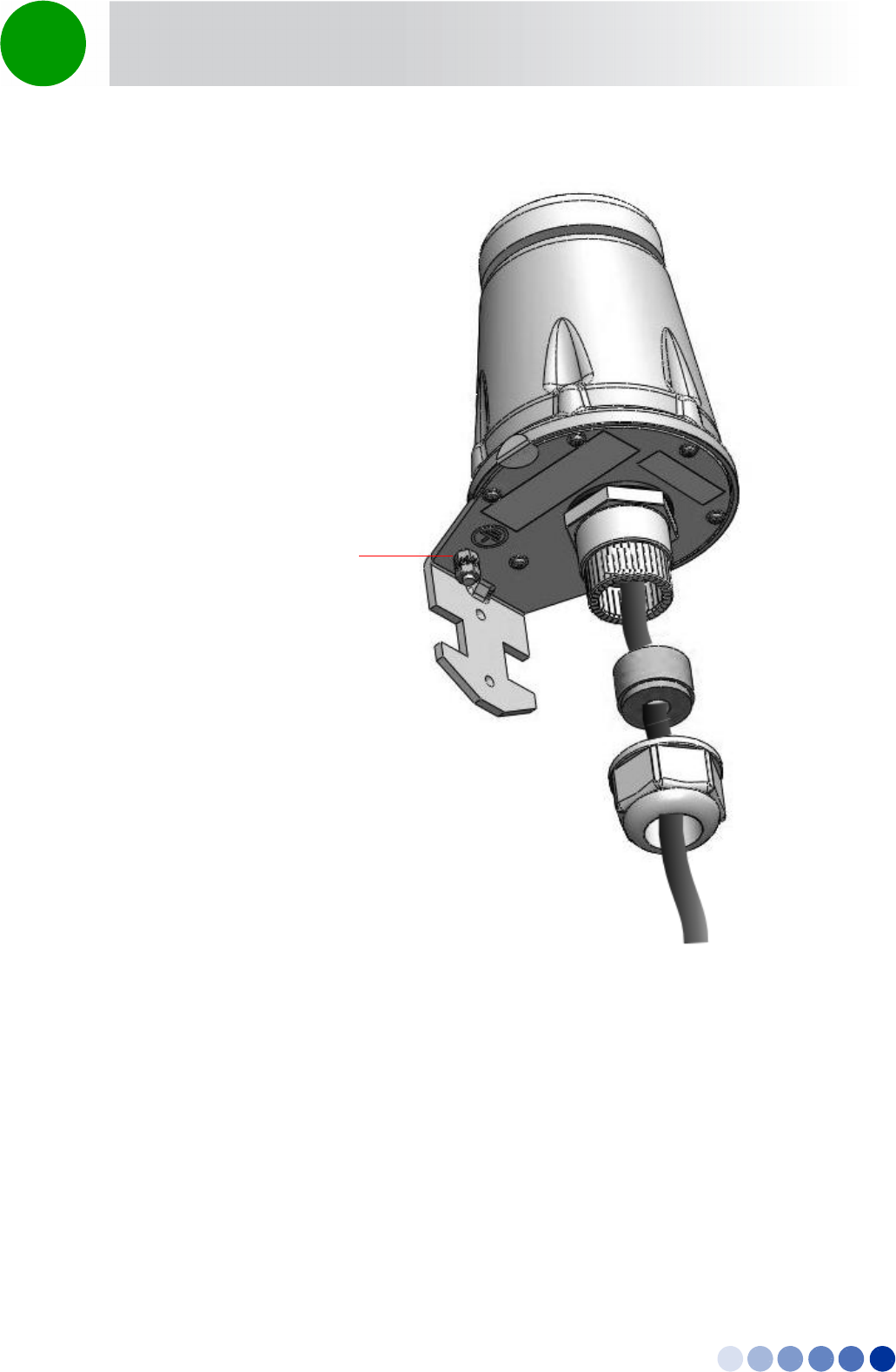
9Connect the grounding cable to the grounding screw located on the bottom panel of the GPS
bracket. Connect the other end of the grounding cable to a good ground (earth) connection
Figure 2-17: Connecting the GPS Cable
Figure 2-18: GPS Bottom View
Rubber Bushing
Gland Nut
Sealing Gland
with RJ-45
Connector
Grounding
4Motion Installation Manual 52
Chapter 2 - BreezeCOMPACT Installation GPS Installation
Figure 2-19: Trimble Lassen GPS Grounding
Grounding screw
4Motion Installation Manual 53
Chapter 2 - BreezeCOMPACT Installation Connecting the BreezeCOMPACT Cables
2.7 Connecting the BreezeCOMPACT Cables
2.7.1 Introduction
This chapter describes how to prepare and connect all the required cables to the BTS. A DC and a DATA
cable are required to connect the BTS to the backhaul.
The BreezeCOMPACT is provided with sealing glands on all the cable connectors. The cables are to be
connected to the BTS by inserting the cable connector through the sealing gland. Some of the cables
provided by Alvarion are supplied crimped and with a sealing gland already attached to them.
For connecting cables to connectors with sealing glands, refer to “Using the Connector Sealing
Accessories” on page 64.
To ensure proper sealing of the glands use only the special wrench supplied with the BTS (see
Figure 2-20).
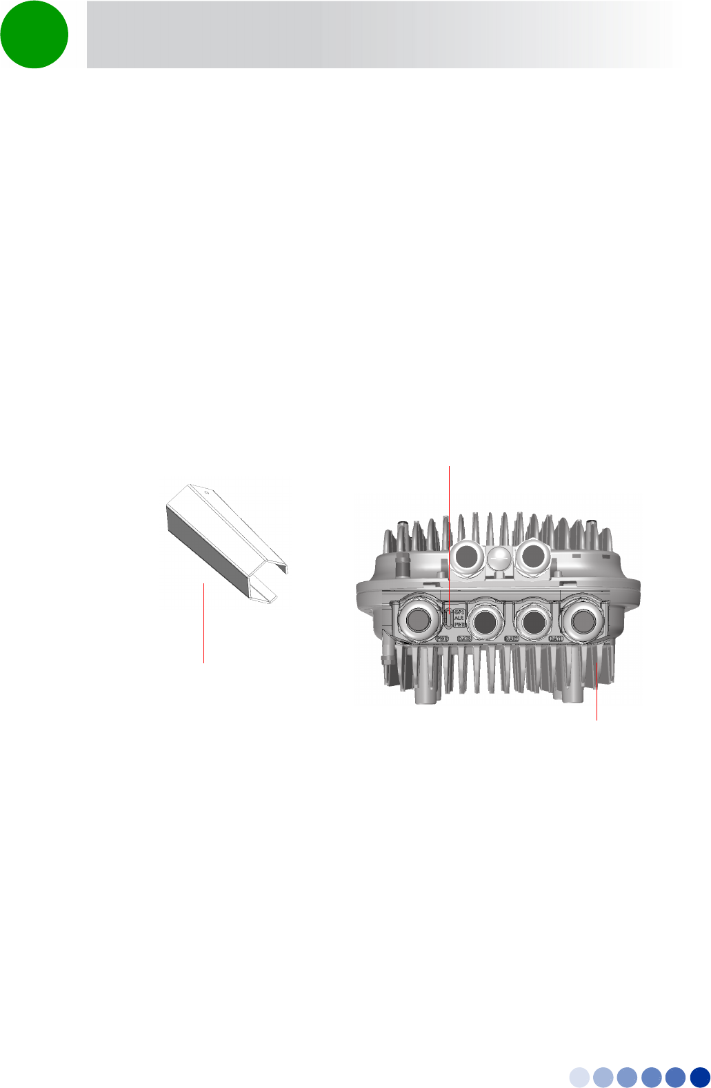
Figure 2-20: BreezeCOMPACT with Sealing Gland Wrench
Sealing gland
wrench
LEDS
Sealing gland
4Motion Installation Manual 54
Chapter 2 - BreezeCOMPACT Installation Connecting the BreezeCOMPACT Cables
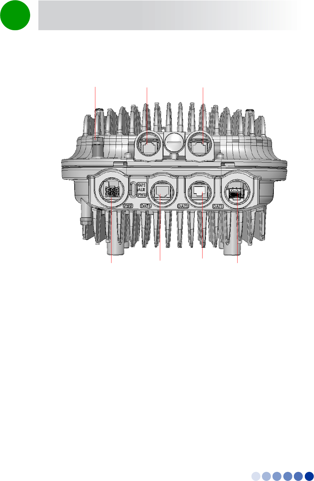
Figure 2-21: BreezeCOMPACT Connectors
PWR (6-pin mini-fit) DAT3 (RJ-45) DAT2 (RJ-45) DAT1(Fiber Optics)
GPS IN (RJ-45) SYNC OUT (RJ-45)Grounding
4Motion Installation Manual 55
Chapter 2 - BreezeCOMPACT Installation Connecting the BreezeCOMPACT Cables
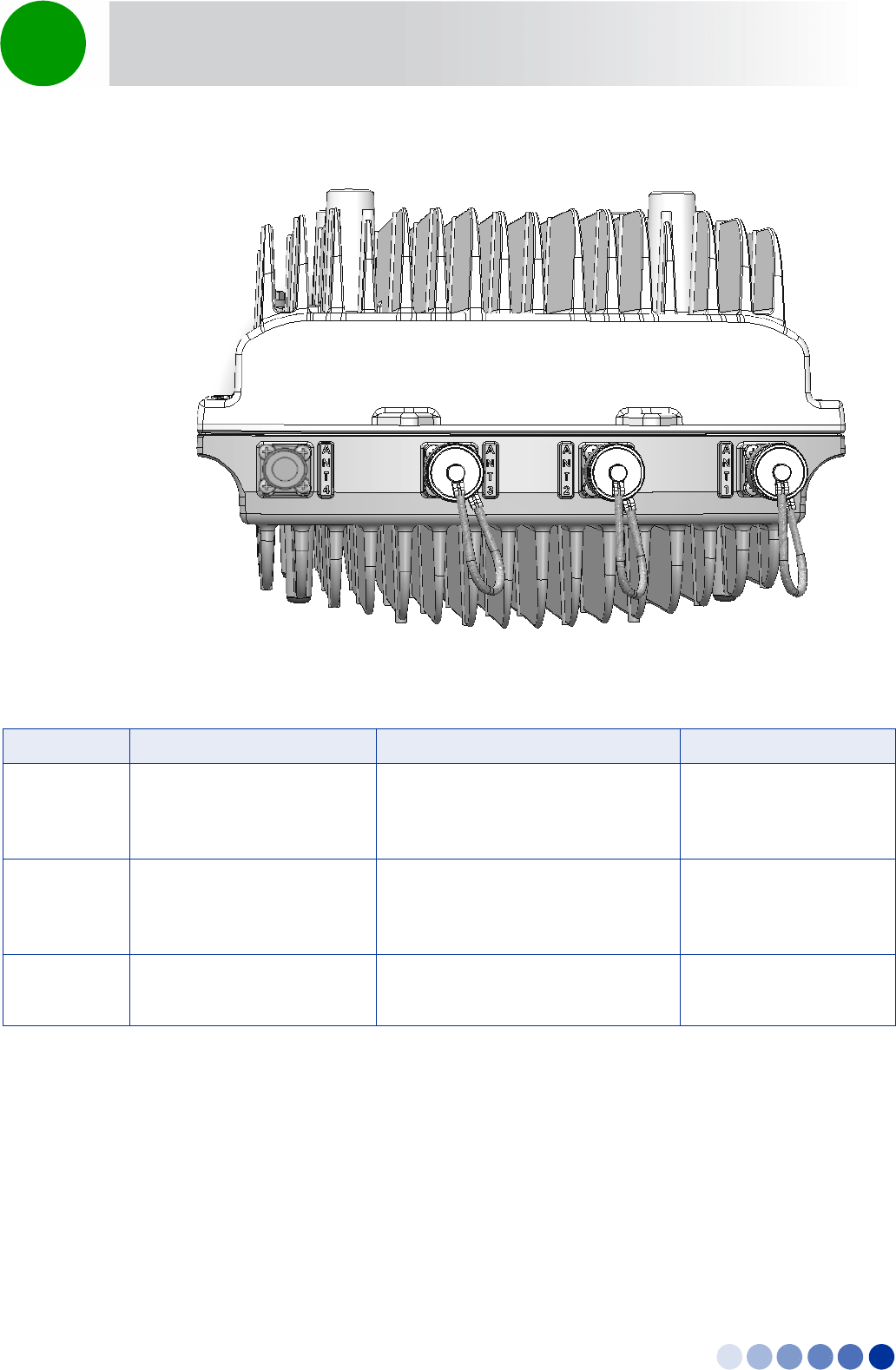
Figure 2-22: BreezeCOMPACT Antenna Connectors
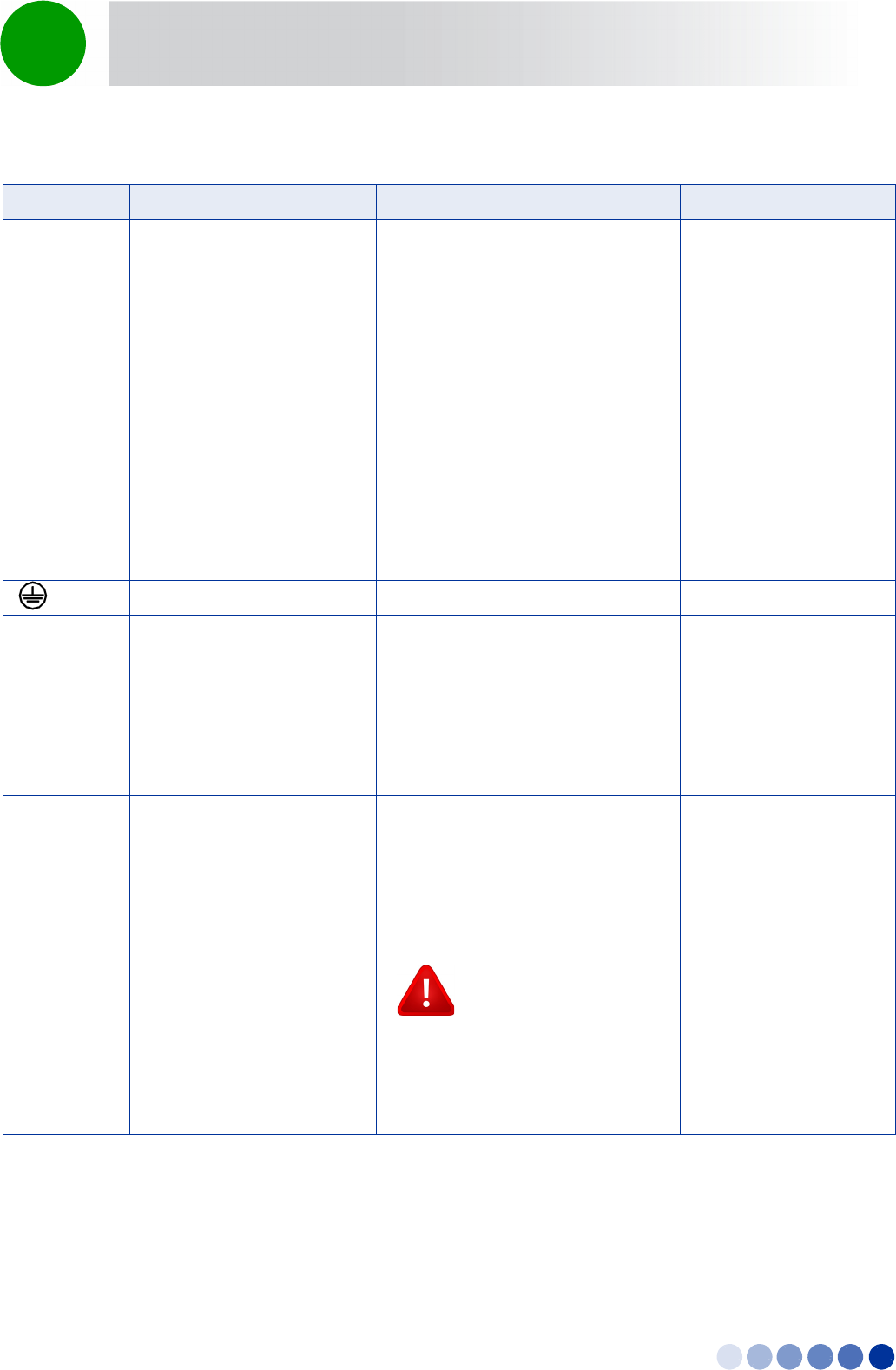
Table 2-2: BTS Connectors
Connection Connector Type Functionality Cable
PWR 4-pin mini-fit Molex Power connection, DC in -40 to -60
VDC at connector input.
Maximum consumption: 150W
Shielded 16AWG
Length: ≤90m
DAT1 10/100/1000BASE-T Optic SFP
shielded LC female
For data and Inband management OM3 50um multimode
optical cable
Length: ≤100m
DAT2 10/100/1000BASE-T RJ-45,
female 1G
For data and Inband management Shielded RJ-45 CAT-5e
Length: ≤100m
4Motion Installation Manual 56
Chapter 2 - BreezeCOMPACT Installation Connecting the BreezeCOMPACT Cables
DAT3 RJ-45 For Out Of Band management or
Data + Inband management:
PoE Data + DC Out
PoE Data + DC In (depending on
configuration)
PoE in ≤ 70W (allowed only for
2x2)
PoE out for camera connection
≤ 20W
OOB management
or
Data +IB management
or
Future Ethernet chain
Shielded RJ-45 CAT-5e
Length: ≤100m
(GND) Grounding screw Connection to ground (earth)
GPS IN RJ-45 Connection to GPS with lightning
arrestors to the master BTS via RS-422
signals,
or
Chaining GPS signals connection to
slave BTS from previous GPS out
connector (future option).
Shielded RJ-45 CAT-5e
Length: ≤20m
SYNC OUT RJ-45 Chain GPS signals between BSTs
(master / slave). Chaining is a future
option.
Shielded RJ-45 CAT-5e
Length: ≤20m
ANT1 - ANT4 4 x N-Type jack, 50 Ohm,
lightning protected
Connection to external antenna(s).
See Section 2.7.8.
CAUTION
To prevent lightning damage to the
unit, connect only DC ground
lightning protected antennas with
short LMR-400 cables (0.5m/1m) to
these ANT1-4 connectors.
LMR-400
Length: ≤1m
Table 2-2: BTS Connectors (Continued)
Connection Connector Type Functionality Cable
4Motion Installation Manual 57
Chapter 2 - BreezeCOMPACT Installation Connecting the BreezeCOMPACT Cables
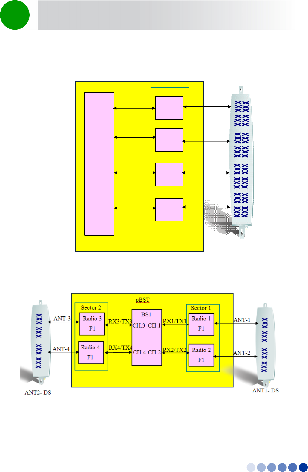
2.7.2 Connection Diagrams
Figure 2-23: Single Sector with Double Dual-Slant Antenna Connections
Figure 2-24: Two Sectors with Two Double Dual-Slant Antenna Connections
RX1/TX1
Sector 1
RX2/TX2
CH.1
CH.2
BS1
Radio 1
F1
Radio 2
F1
Radio 3
F1
CH.3
RX3/TX3
p
BST
Radio 4
F1
CH.4 RX4/TX4
ANT-1
ANT-2
ANT-3
ANT-4
ANT-Double DS
BTS
4Motion Installation Manual 58
Chapter 2 - BreezeCOMPACT Installation Connecting the BreezeCOMPACT Cables
2.7.3 Connecting the Grounding Cable
Use 10 AWG cable for grounding.
When grounding the unit, use the GND (ground) screw on the unit as a grounding point. The Grounding
screw (marked ) is located on the connectors panel of the unit (see Figure 2-21).
1Connect one end of a grounding cable to the ground terminal and firmly tighten the grounding
screw.
2Connect the opposite end of the grounding cable to a ground connection.
2.7.4 Preparing and Connecting the Data Cable (RJ-45
Connector)
To prepare a Data cable, use either the cable kit available from Alvarion or one of the authorized
indoor-outdoor CAT 5E cables listed in Table 2-4, and follow the wiring instructions as detailed herein.
The Alvarion's cable kit includes an RJ-45 connector and a protective cover for the connector. This cable
should be used when the power is fed through the DC 48V connector.
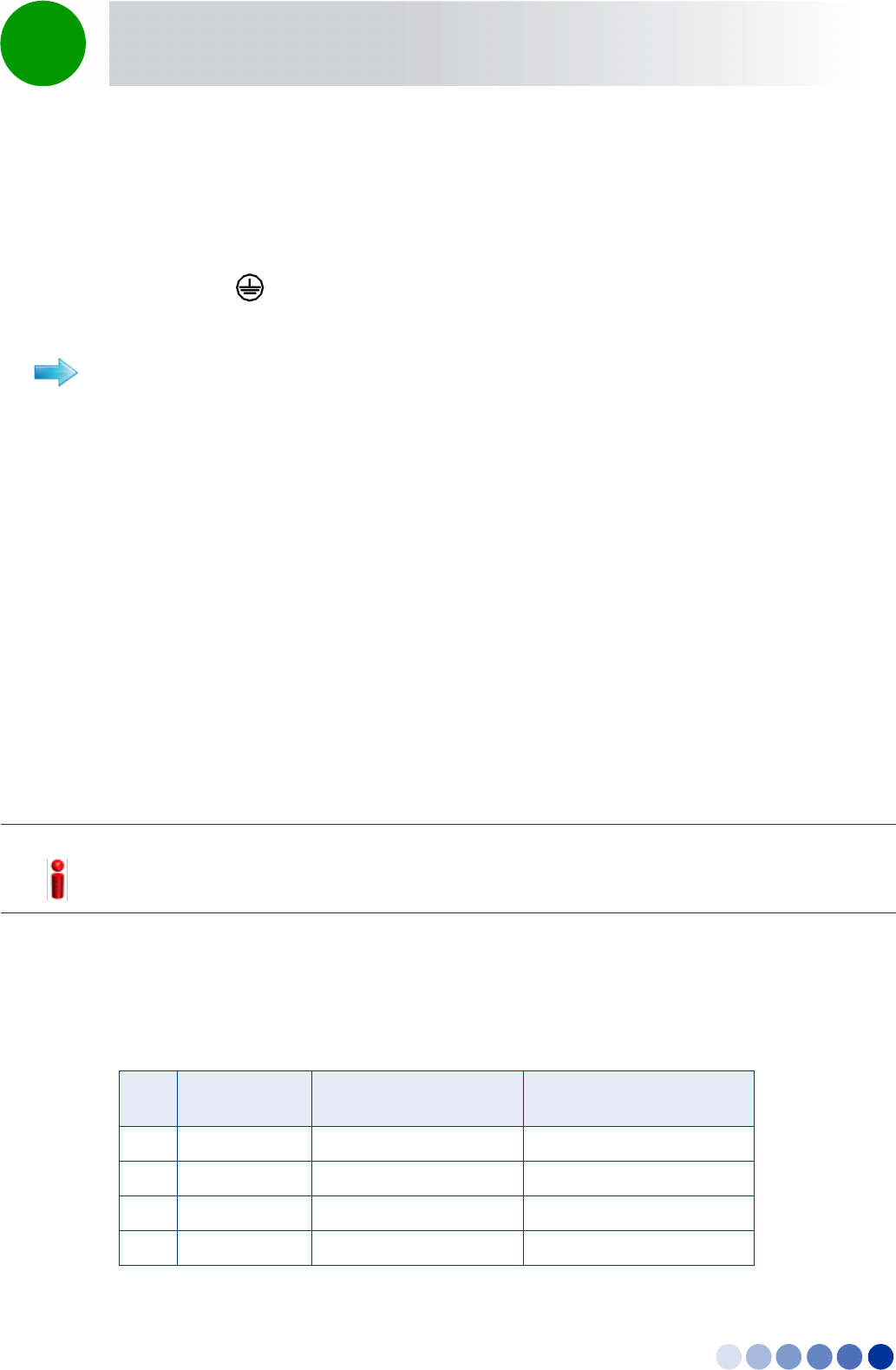
When connecting any data equipment (switch, hub, PC) to the DAT 3 connector, use only a 4-wire cable,
connecting pins 1, 2, 3 and 6. Power on pins 4, 5, 7 and 8 may damage your equipment, therefore these
pins should not be connected.
When feeding power to a backhauling system, use an 8-wire cable. The following table shows the
required wire pair pin-to-pin connections, for 4-wire and 8-wire cables. + means connected, - means not
connected.
To connect the grounding cable:
NOTE!
It is recommended not to crimp 4-5 and 7-8 pairs as power might be fed towards the network device
connected to the BTS.
Table 2-3: Wire to Pin Mapping for Data Cable for the BTS
Pin Description Connection to Data
Equipment (4-wire)
Connection for
Backhauling (8-wire)
1 Ethernet TXP
2 Ethernet TXN
3 Ethernet RXN
4 PoE 48V Pos. N/A
4Motion Installation Manual 59
Chapter 2 - BreezeCOMPACT Installation Connecting the BreezeCOMPACT Cables
5 PoE 48V Neg. N/A
6 Ethernet RXN
7 PoE 48V Pos N/A
8 PoE 48V Neg. N/A
Figure 2-25: RJ-45 Data Connector
Table 2-4: Approved Category 5E Ethernet Cables
Manufacturer Part Number
UNIXTAR
www.unixtar.com.tw
C5ES4P24
WESTERN
www.westernwire.org
KF804E1D
Table 2-3: Wire to Pin Mapping for Data Cable (Continued)for the BTS (Continued)
Pin Description Connection to Data
Equipment (4-wire)
Connection for
Backhauling (8-wire)
1 234 5678
1 + 2
4 + 5
7 + 8
3 + 6
4Motion Installation Manual 60
Chapter 2 - BreezeCOMPACT Installation Connecting the BreezeCOMPACT Cables
For connecting cables to connectors with sealing glands, refer to “Using the Connector Sealing
Accessories” on page 64.
1Connect one end of the cable to the DAT3 connection on the BTS.
2Connect the other end of the data cable the backhauling equipment. See Figure 2-23.
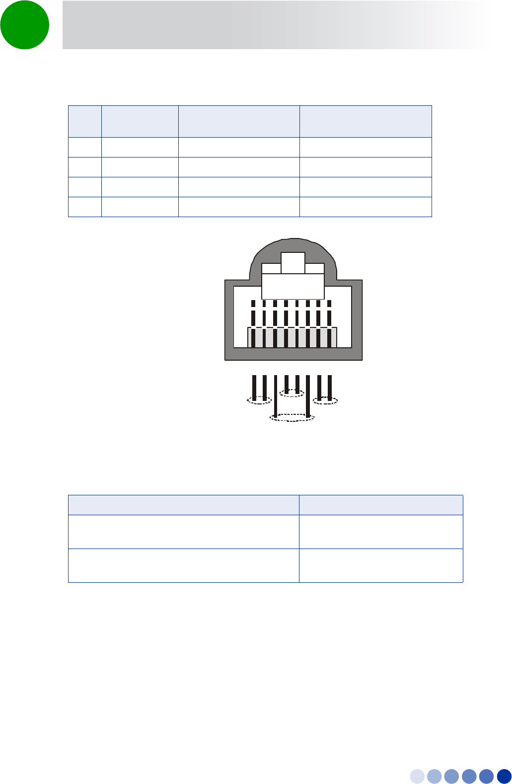
To assemble the RJ-45 connector:
1 Thread the RJ-45 plastic cover on the
cable.
2 Reveal 5cm of outer sleeve, then reveal
4cm of the inner sleeve.
3 Release all wires and arrange them in
order, then cut them to 1cm lengths.
4 Insert the wires into the connector and
press it using a standard tool (it is
recommended to solder the shield drain
wire to the connector as in the picture).
Note the Pin assignment for each cable.
5 Push the plastic cover into place.
To connect the data cable:
INFORMATION
The combined lengths of the Ethernet cables should not exceed 100m.
4Motion Installation Manual 61
Chapter 2 - BreezeCOMPACT Installation Connecting the BreezeCOMPACT Cables
2.7.5 Preparing and Connecting the Power Cable
Cable type: 6-pin mini-fit, DC in -40 to -60VDC at connector input. 2 wires are connected to -48VDC,
2 wires are connected to return signal and 1 wire to the Ground.
Maximum power consumption:150W
1Make sure you have the following components:
»Outdoor shielded 4x16AWGpower cable
»Five terminals for Mini-Fit 16 AWG wires
»Mini-fit 6-pin housing that fits the terminals
»A crimping tool for preparing the wires, suitable for 20-16 AWG/0.1-1.5 mm2 wires with open
barrel terminals. It is recommended to use the Pressmaster® DRB-0115.
2Insert the cable through the sealing gland.
3Remove as small a length as possible of the cable's external jacket to expose the wires.
4Insert a terminal into the appropriate Pressmaster slot.
5Insert the wire into the terminal within the slot and squeeze the tool's handles to crimp the terminal.
To prepare the power cable:
Figure 2-26: Open Barrel Terminal
4Motion Installation Manual 62
Chapter 2 - BreezeCOMPACT Installation Connecting the BreezeCOMPACT Cables
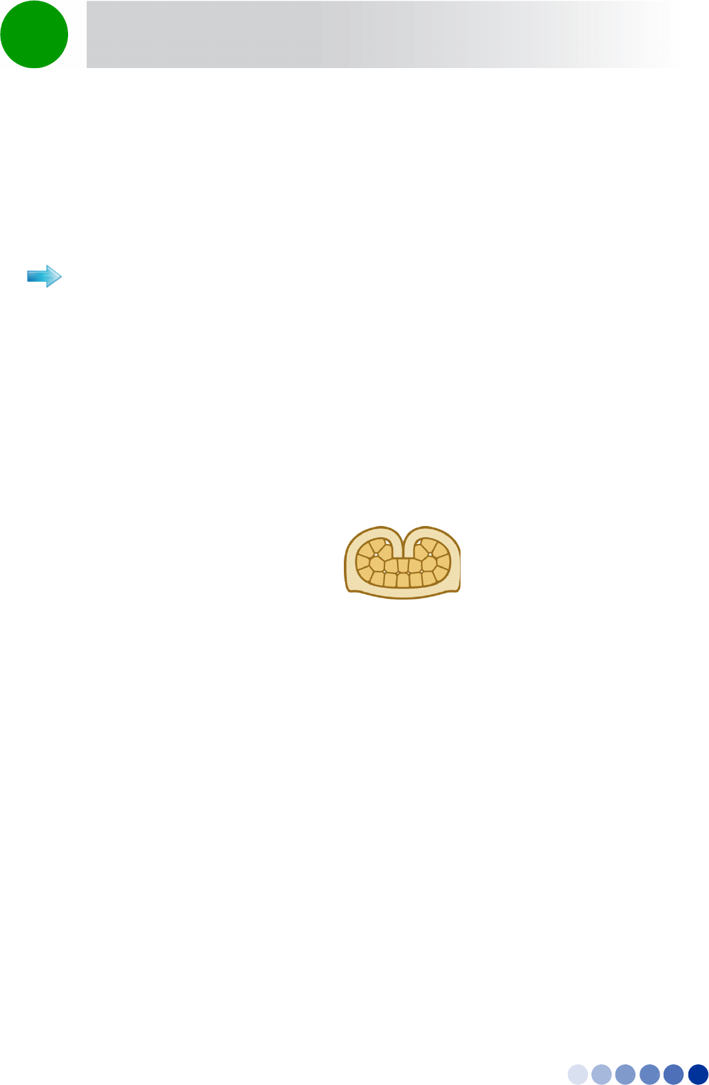
6Repeat steps 3 and 4 for each of the five wires.
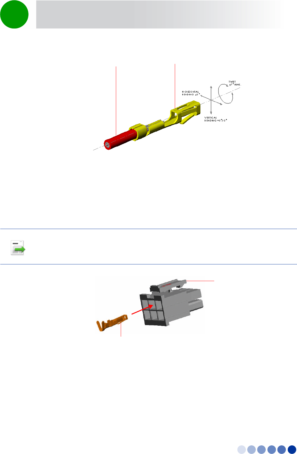
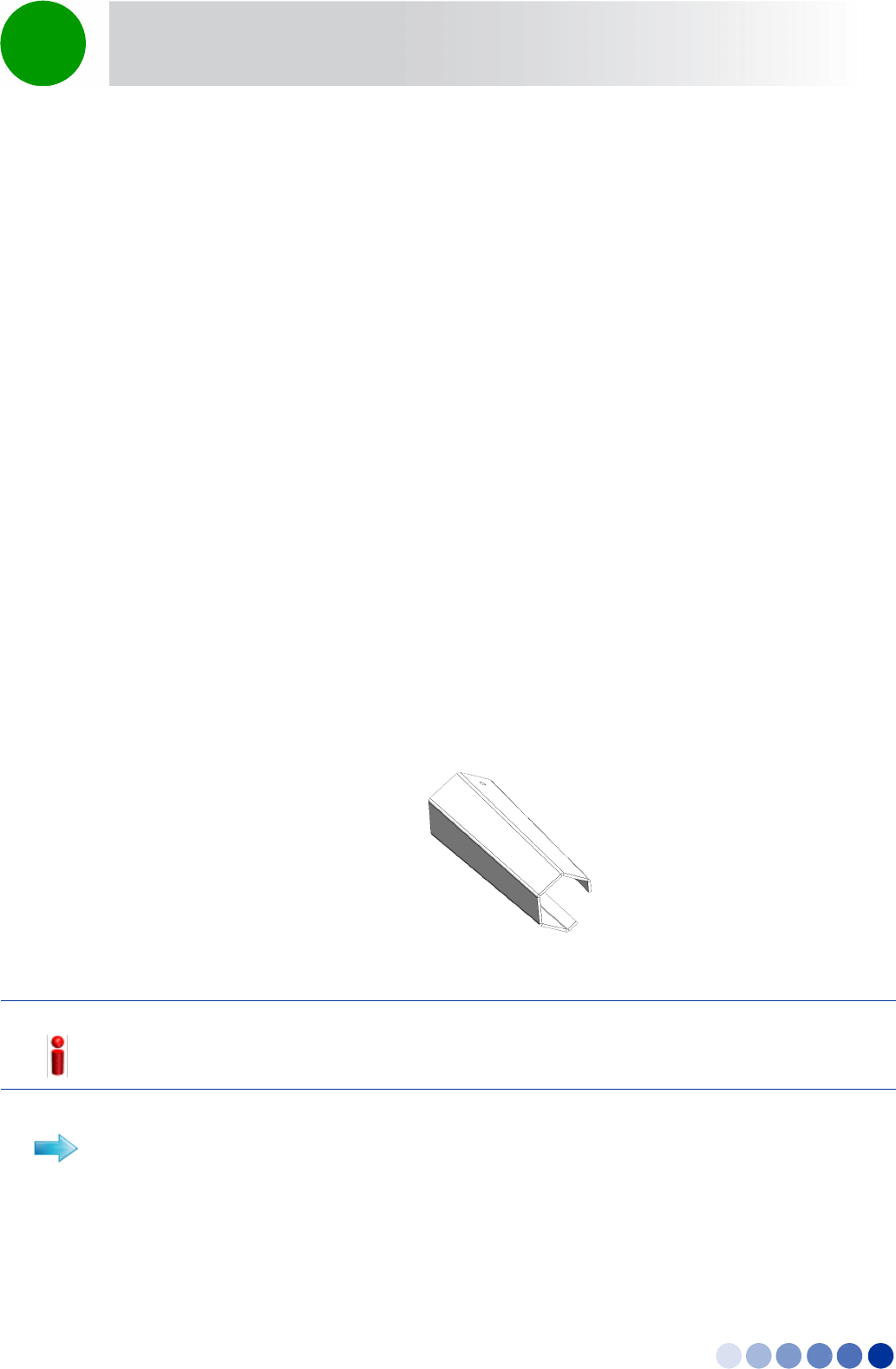
7To insert a contact into the housing, align the contact with the desired cavity at the rear of the
housing as shown in Figure 2-28. In all rows the locking lance must be facing away from the housing
latch to engage the contact in the cavity. Push the contact straight into the cavity until an audible click
is heard. Give the lead a light tug to confirm that the contact is locked in place.
Figure 2-27: Crimped Wire
INFORMATION
Figure 2-28 reflects the direction in which the pins are connected. Make sure that you connect the pins
accordingly.
Figure 2-28: Inserting a Contact into the Housing
TerminalWire external
jacket
Housing
latch
Locking lance
4Motion Installation Manual 63
Chapter 2 - BreezeCOMPACT Installation Connecting the BreezeCOMPACT Cables
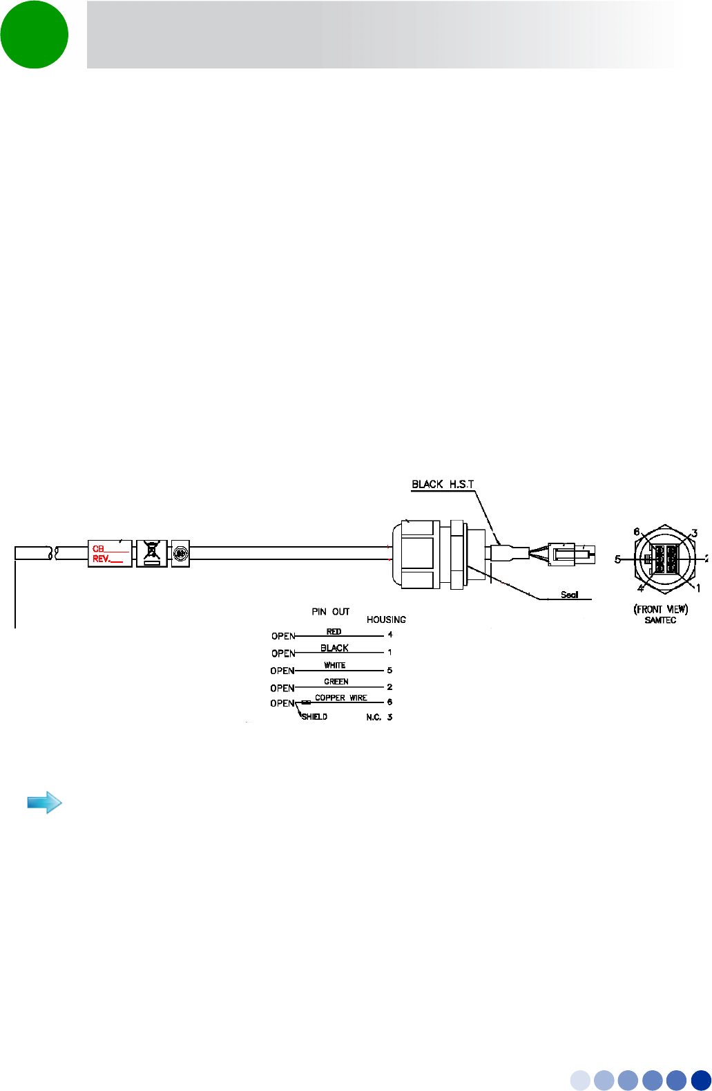
8Connect the wires to the mini-fit connector as follows (see Figure 2-29):
»Pins 1 (48V_RTN): Black (16 AWG min. wire)
»Pin 2 (48V_RTN): Green (16 AWG min. wire)
»Pin 3: Not connected
»Pin 4 (+48V): Red (16 AWG min. wire)
»Pin 5 (+48V): White (16 AWG min. wire)
»Pin 6 (Shield) - cable shield)
9Attach suitable terminal rings to the side that connects to the power source.
10 When connecting to a circuit breaker, see Figure 2-29 below for the location on the cable. Use a 20A
breaker.
For connecting cables to connectors with sealing glands, refer to “Using the Connector Sealing
Accessories” on page 64.
1Connect the cable to the PWR connector on the unit and close the sealing gland.
2Connect the other end of the power cable (with the terminal rings) to the DC power source.
3Connect the AC/DC power supply to the mains
The system is now powered-up.
Figure 2-29: Power Cable for BreezeCOMPACT
To connect the power cable:
4Motion Installation Manual 64
Chapter 2 - BreezeCOMPACT Installation Connecting the BreezeCOMPACT Cables
2.7.6 Connecting the GPS Cable
Connect the data cable to from the GPS to the GPS IN connector located on the BTS panel (see
Figure 2-21).
2.7.7 Using the Connector Sealing Accessories
The outdoor equipment is supplied with the connectors sealed with either flexible plastic covers, plastic
caps or sealing glands. Some of the cables provided by Alvarion are supplied crimped and with a sealing
gland already attached to them.
When there is a flexible cover and you need to use the connector, remove the cover and connect the
cable. Use appropriate sealing methods to ensure protection against rain and moisture.
When there is a cap covering the connector and you need to use the connector, add a sealing gland
before connecting the cable.
For connectors with a sealing gland, insert the cable into the gland before connecting it, as described in
the procedures below. There are two sizes of sealing glands, labeled 10.5 and 7.9 on their plug.
After connecting each cable, make sure that the nut of each sealing gland is properly tightened and that
the sealing gland is tightly attached to protective body of the connector to ensure proper sealing against
rain and moisture.
Use only the special wrench supplied with the equipment (see Figure 2-30).
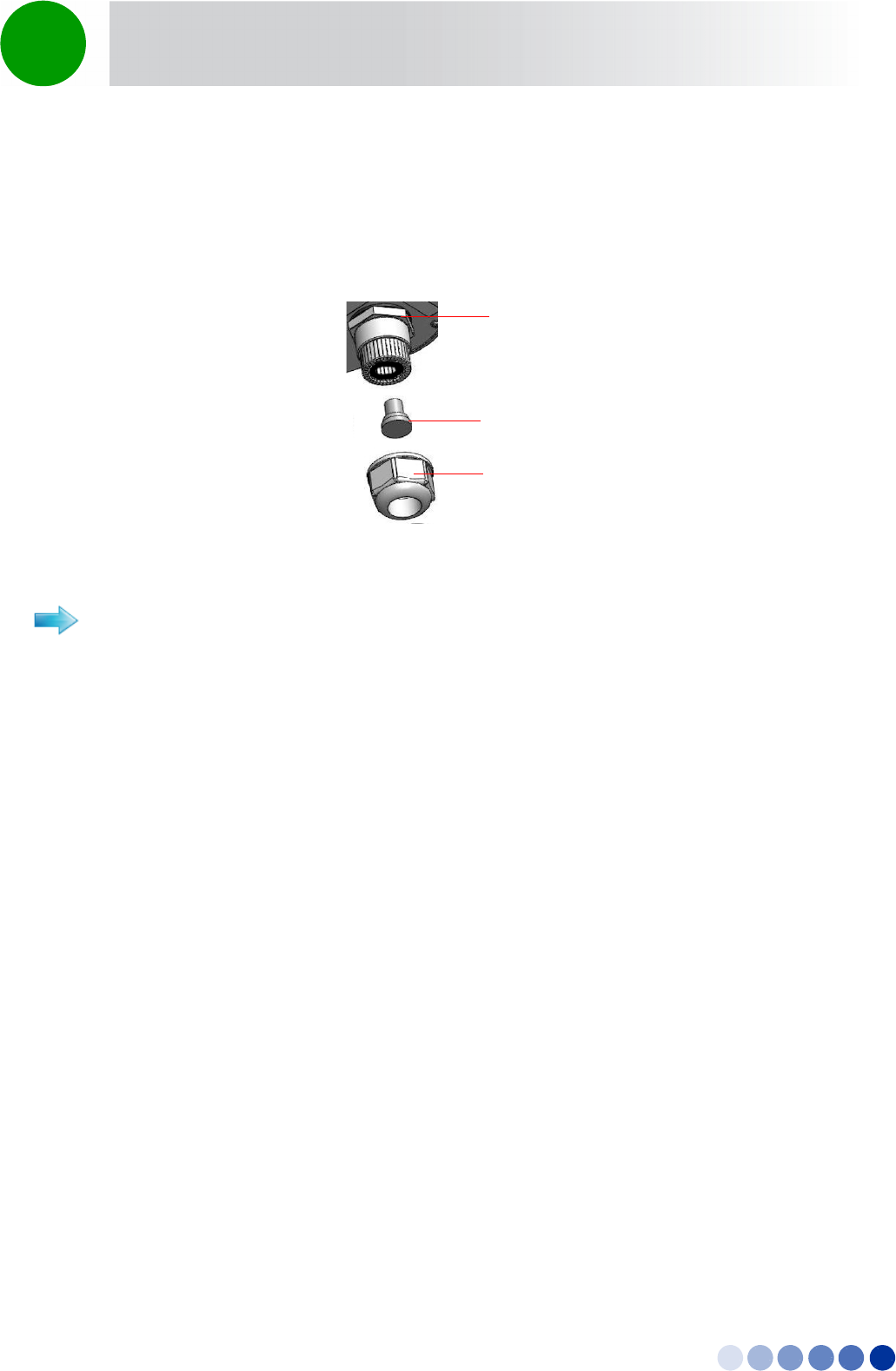
Refer to Figure 2-16.
1Release the sealing gland nut from the gland base and remove the plug.
Figure 2-30: Sealing Gland Special Wrench
NOTE!
Unused connectors should always be sealed with the cover firmly tightened to the protective body of
the connector.
To connect a cable to a connector with a small gland (7.9):
4Motion Installation Manual 65
Chapter 2 - BreezeCOMPACT Installation Connecting the BreezeCOMPACT Cables
2Thread the cable through the released nut.
3Insert the cable through the gland and push it until it is connected to the unit connector.
4Return the sealing nut to the gland and firmly tighten to ensure proper sealing.
Refer to Figure 2-32.
1Remove the sealing gland from the unit.
2Release the sealing gland nut from the gland base and remove the plug.
3Remove the rubber bushing from the sealing gland.
4Thread the cable through the released nut and the rubber bushing.
5Crimp the cable and assemble the appropriate connector.
6Connect the cable to the connector on the outdoor unit.
7Insert the rubber bushing into the gland base.
8Return the gland base to the outdoor unit and tighten firmly.
9Return the gland nut to the gland base and firmly tighten to ensure proper sealing.
Figure 2-31: Small (7.9) Sealing Gland Components
To connect a cable to a connector with a large gland (10.5):
Sealing Gland Base with
connector underneath
Sealing Gland Nut
Plug
4Motion Installation Manual 66
Chapter 2 - BreezeCOMPACT Installation Connecting the BreezeCOMPACT Cables
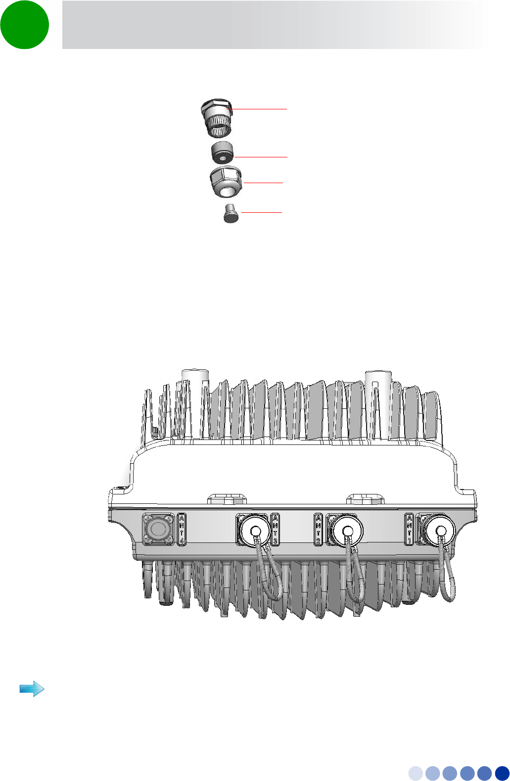
2.7.8 Connecting to External Antennas
Four N-type connectors are used for the optional external antenna connection (see Figure 2-33). The
connectors must have an impedance of 50 Ohm and lightning protected.
Figure 2-32: Large (10.5) Sealing Gland Components
Figure 2-33: External Antenna Connections
To connect the RF cable (units with external antenna):
Sealing Gland Plug
Rubber Bushing
Sealing Gland Base
Sealing Gland Nut
4Motion Installation Manual 67
Chapter 2 - BreezeCOMPACT Installation Connecting the BreezeCOMPACT Cables
1Connect one end of the coaxial RF cable to the connector (marked ANT1 to ANT4) located on the rear
panel of the unit.
2Connect the other end of the RF cable to the antenna.
3Seal the RF connectors properly to protect against rain and moisture.
INFORMATION
The recommended minimum distance between any two antennas in neighboring sectors is 0.5 m.
The minimum distance between any two antennas in the same sector (space diversity configuration) is
1.3 m, that is 10 lambda (λ), where λ=C/Frequency (Hz). C is the speed of light in centimeters per
second which is equal to 29,979,245,800.
4Motion Installation Manual 68
Chapter 2 - BreezeCOMPACT Installation System Initial Verification
2.8 System Initial Verification
After powerup, the BTS automatically starts a self-testing procedure to verify that the BTS has been
correctly assembled and installed on site, all its components are functioning properly, and that it is now
ready for commissioning. During the self-test, the LEDs indicate the working status of the various
components.
1Verify that the BTS is connected to an AC power source.
2Upon completion of the internal test and boot up (up to 5 minutes), verify that the following LEDs are
lit as follows:
Upon power-up completion, the BTS is ready for basic network definition.
To perform testing:
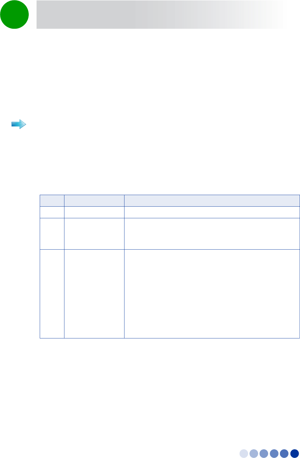
Table 2-5: BreezeCOMPACT LEDs
Name Description Functionality
PWR Power indication Green - Power provided to the unit is OK
ALRM Alarm indication Lights at power up
Turns off after power up is complete
Lights on runtime in case of critical failure
GPS GPS status indication Lights at power up
Turns off after power up is complete
Lights when the GPS is reporting at least four satellites or more
reception.
Blinks (0.5 Sec on, 0.5 Sec off) when the number of satellites
decreases from 4 to 3 or 2 satellites or the min. configured value.
Turns off when only one satellite is received, or the minimum
configured value of GPS is not operational or not installed.
Lights again when the unit is regaining satellites reception of 4
satellites or more.

Chapter 2 - Commissioning
In This Chapter:
“Introduction” on page 41
“Configuring Parameters Required for Management Connectivity” on page 42
“Activating the Unit” on page 46

BreezeCOMPACT System Manual 41
Chapter 2 - Commissioning Introduction
2.1 Introduction
After completing the installation process some basic unit's parameters must be configured locally using
the Monitor program to enable discovery by the Element Management System and remote management
of the unit.
Refer to “The Monitor Program” on page 81 for information on how to access the Monitor program
using Telnet and how to use it.
It is assumed that the unit is a new one (was never configured after being shipped from factory).
Otherwise, it is recommended to reset the unit to its factory default values before proceeding with
following configuration steps: Enter the Monitor program and select BTS>Unit Control>ShutDown
Operation>Update>resettoFactoryDefault (you will be prompted to confirm the requested action).

BreezeCOMPACT System Manual 42
Chapter 2 - Commissioning Configuring Parameters Required for Management Connectivity
2.2 Configuring Parameters Required for
Management Connectivity
The following section describes the minimum mandatory configuration actions required to allow remote
management of the site and to enable discovery by the Element Management System:
Configuring the BTS Number
Configuring the Management Interface Connectivity Mode Parameter
Configuring the IP Interfaces Parameters
Configuring the L1 and L2 Parameters (if necessary)
Configuring the SNMP Authorized Manager and Traps Manager
Applying the Configuration
2.2.1 Configuring the BTS Number
In the Main menu of the Monitor program, select BTS>General>Update and configure the BTS number.
The BTS Number must be unique in the Radio Access Network. The default (0) is not a legitimate value.
2.2.2 Configuring the Management Interface Connectivity
Mode Parameter
The default Connectivity Mode is inband. If a different Connectivity Mode is required, select
BTS>Connectivity>Management Interface>Update. You will be prompted to configure the Connectivity
Mode.
2.2.3 Configuring the IP Interfaces Parameters
For more information on IP Interfaces parameters refer to “Configuring the IP Interfaces Parameters” on
page 42. Note that configuration of certain parameters may depend on the value to be configured for
the BS Bearer IP Address (see )
Select BTS>Connectivity>IP Interfaces>Update. You will be prompted to configure the following
parameters (for some parameters you may just press Enter to keep the default value):
Bearer Subnet Mask (the default is 255.255.255.0).
Bearer Next Hop Gateway. Must be within the range defined by BS Bearer IP Address and Bearer
Subnet Mask. The default is 0.0.0.0. Must be changed to a valid value if IP addresses of core network
equipment is not within the range defined by BS Bearer IP Address and Bearer Subnet Mask.
Bearer VLAN ID (default 11).
Default Authenticator IP. The default is 0.0.0.0. Must be changed to a valid value if IP address of
default authenticator ASN-GW is not within the range defined by BS Bearer IP Address and Bearer
Subnet Mask.