Alvarion Technologies COMPACT3X Base station transceiver User Manual Compact System Manual
Alvarion Technologies Ltd. Base station transceiver Compact System Manual
Contents
- 1. User manual, part 1
- 2. User manual, part 2
- 3. User manual
- 4. Response_FCC_22854_June-17-2012
User manual, part 2
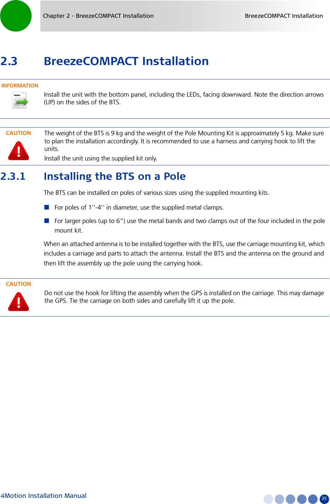
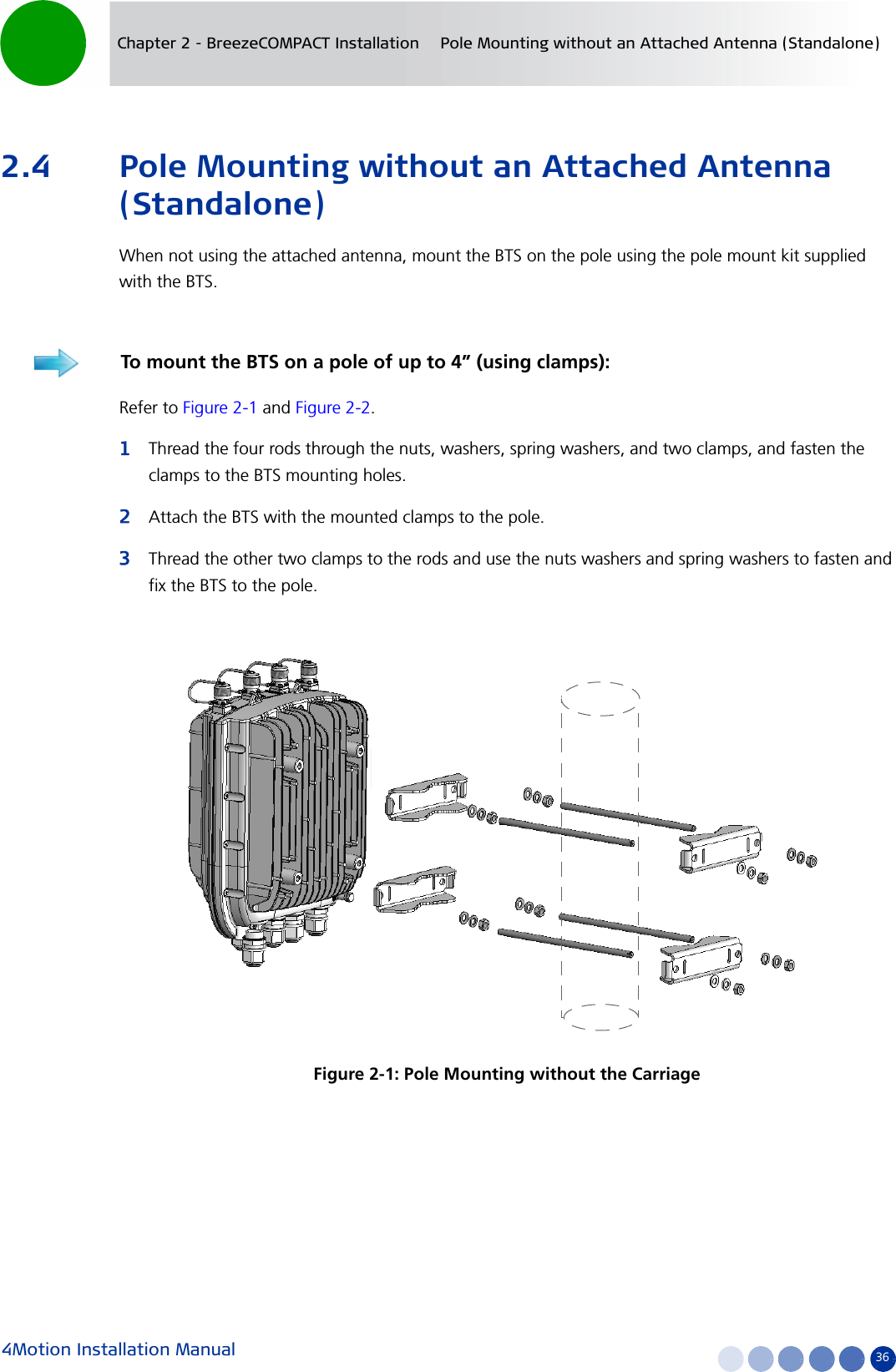
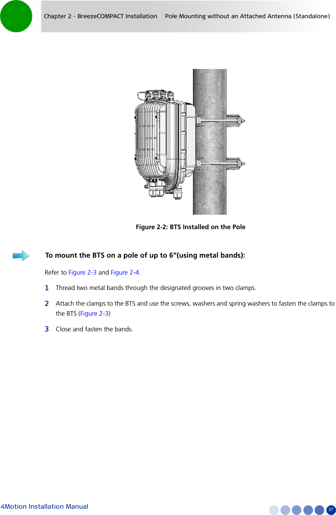
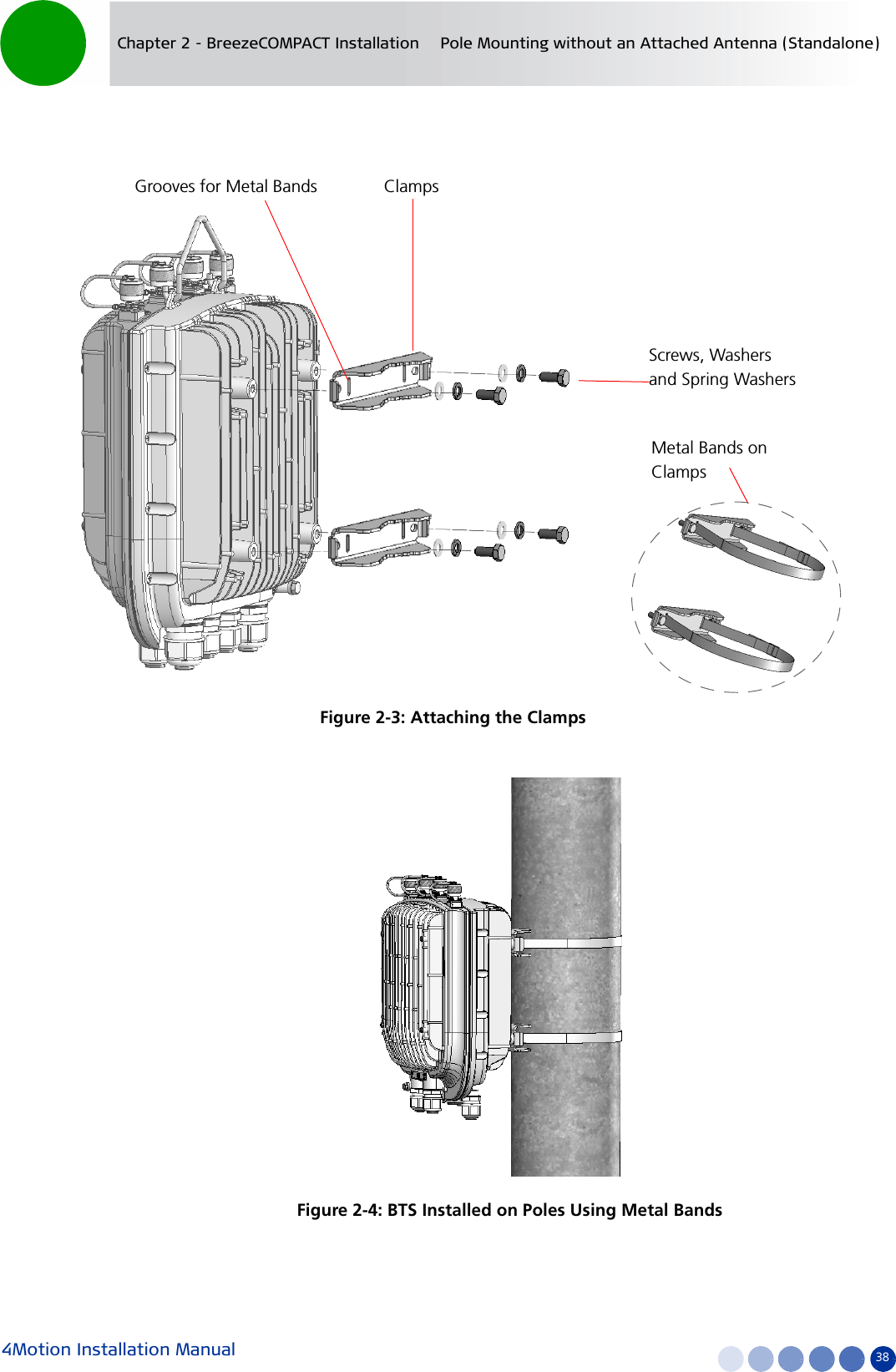
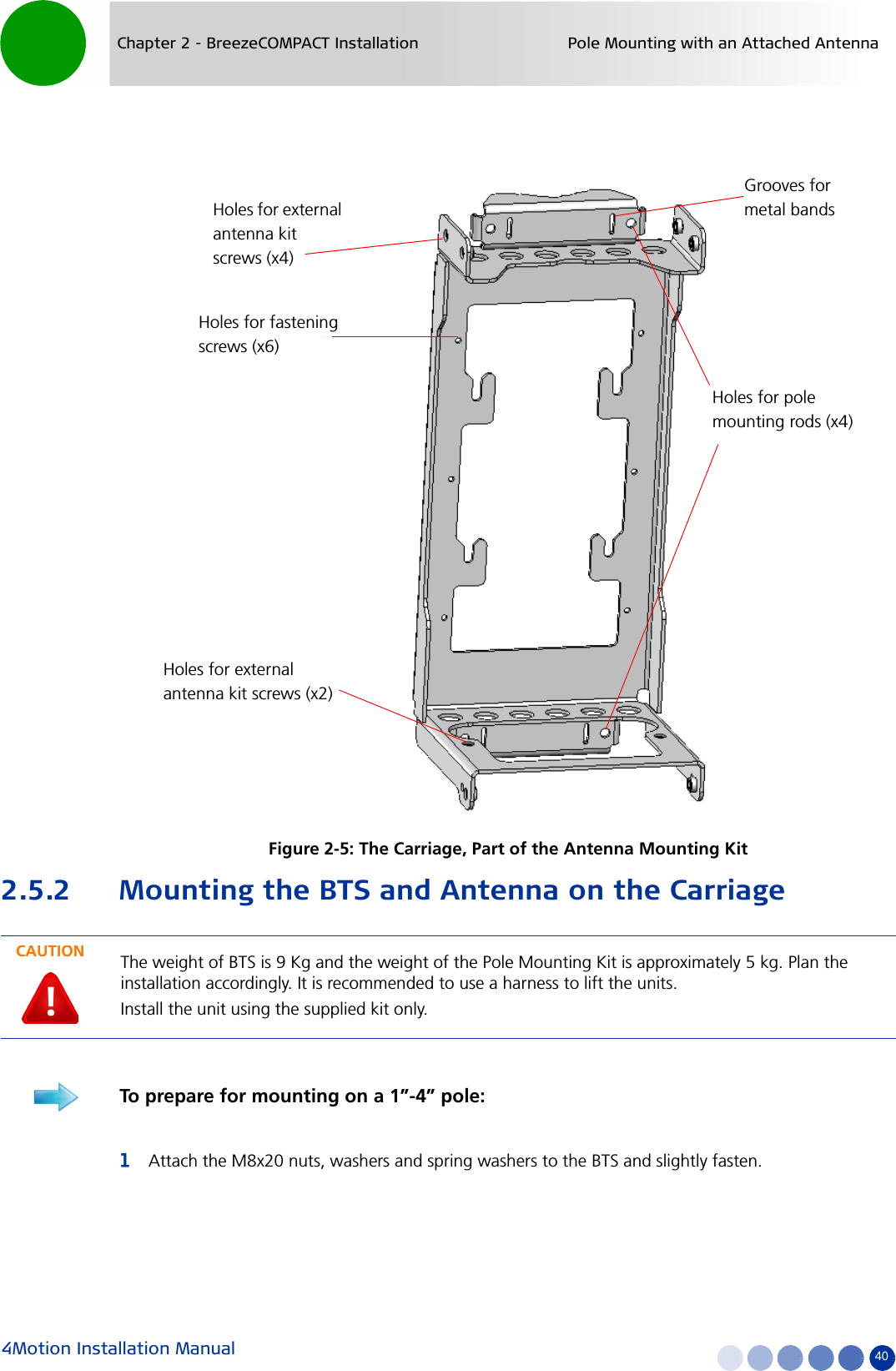
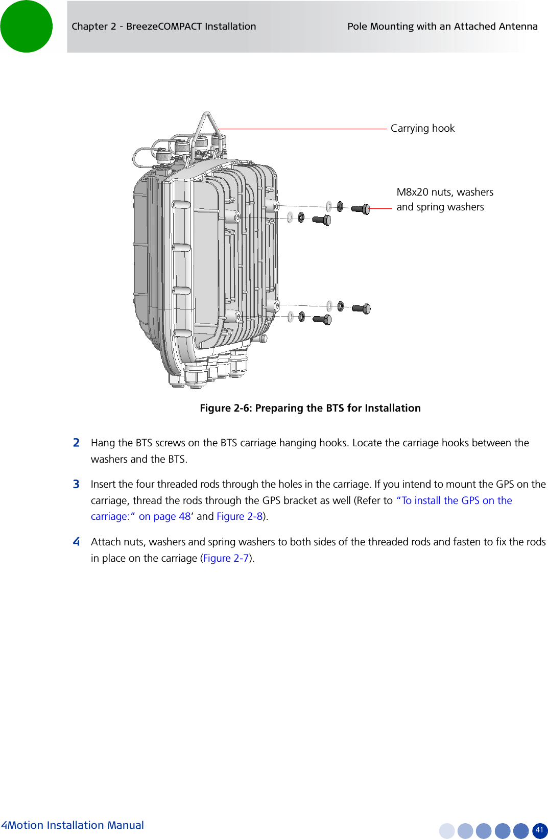
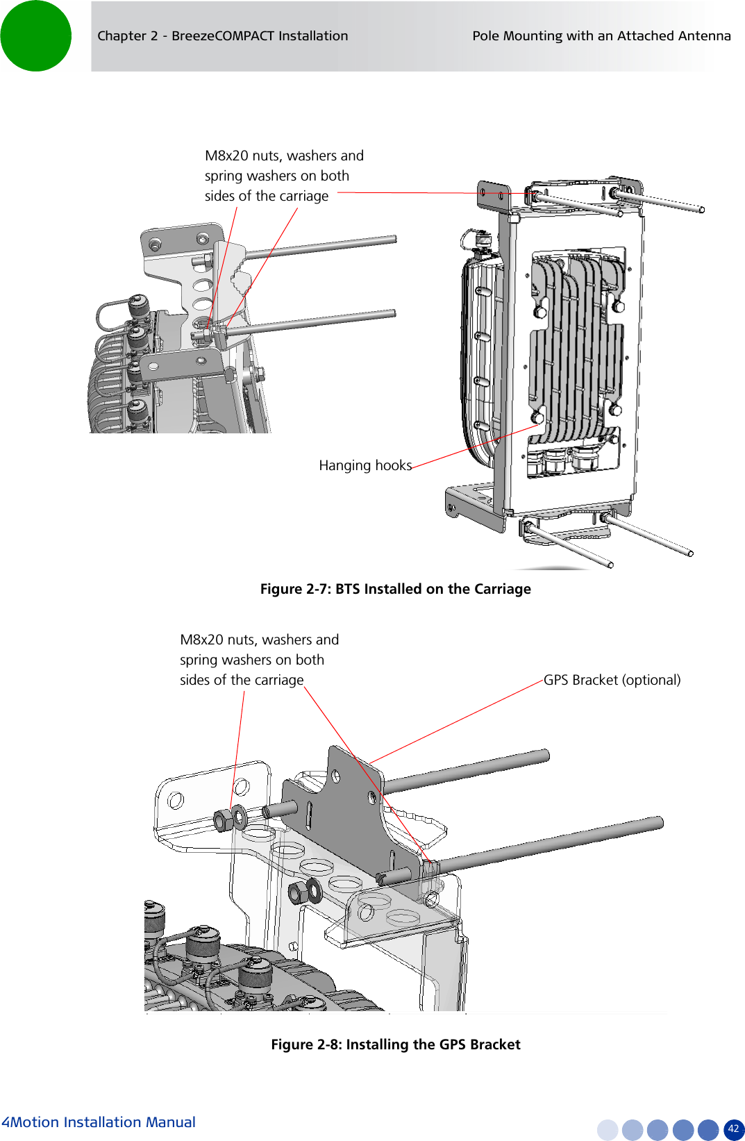
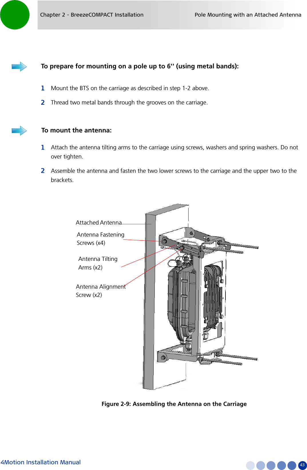
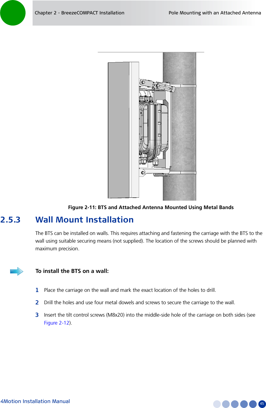
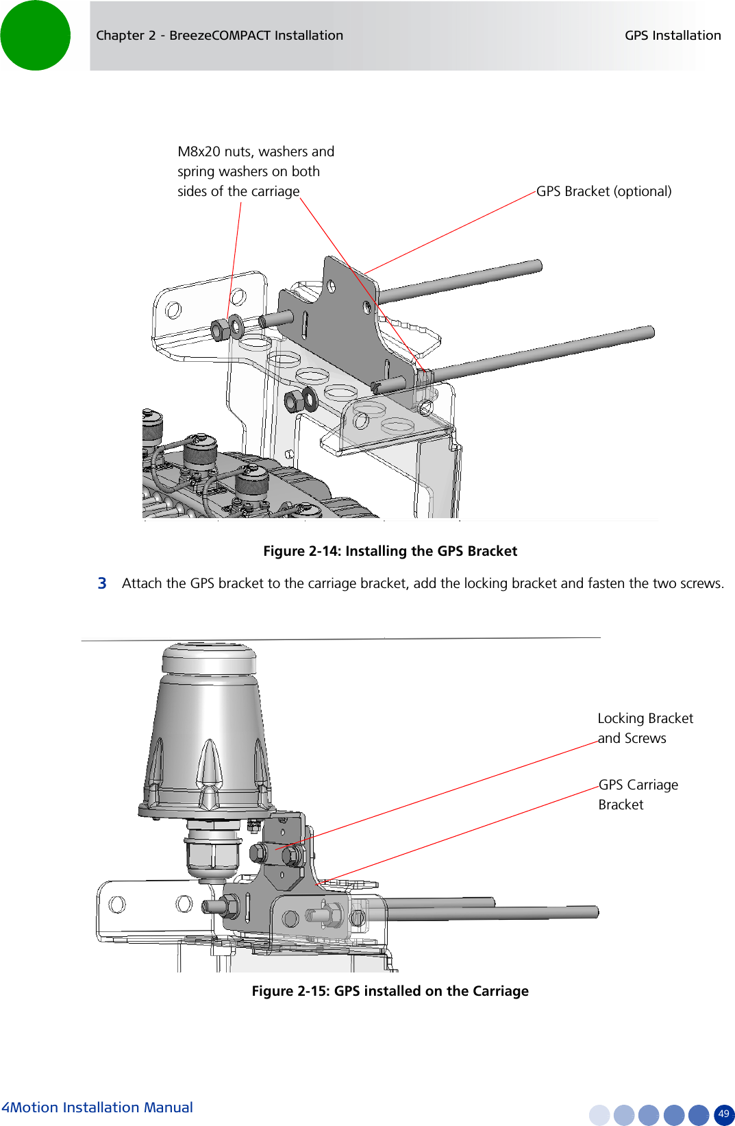
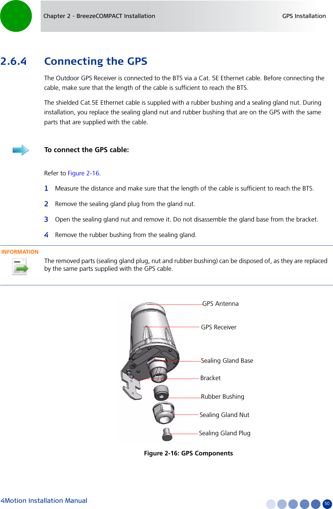
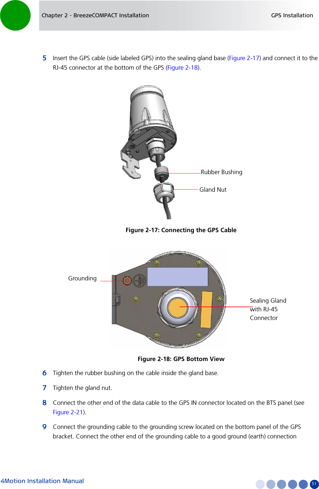
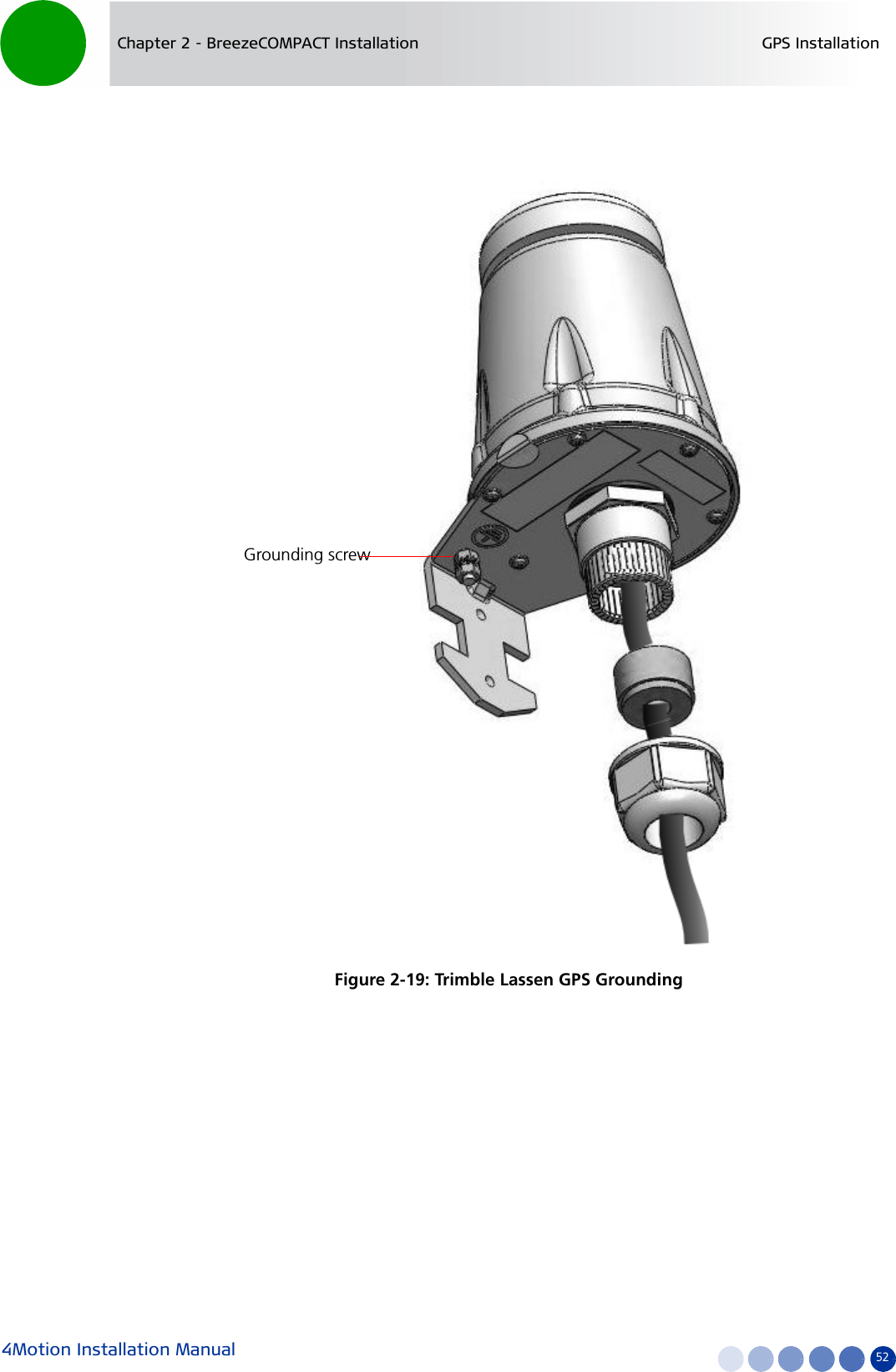
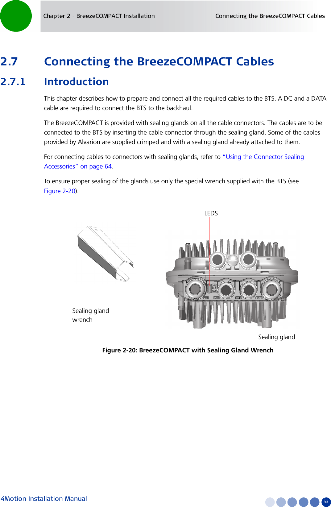
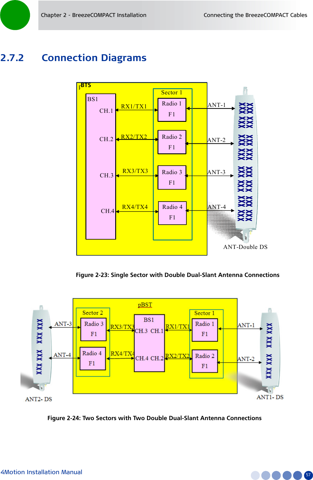
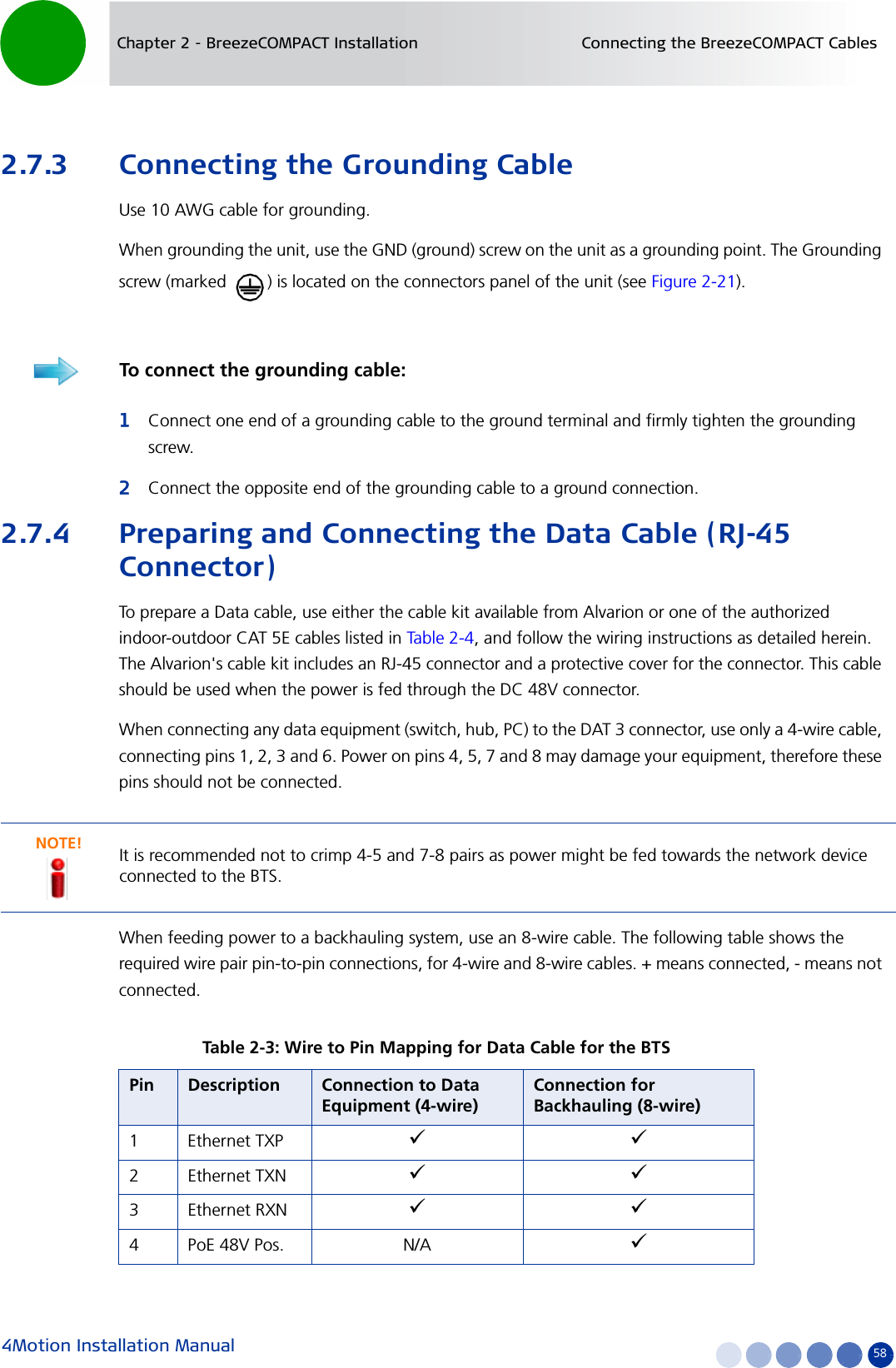
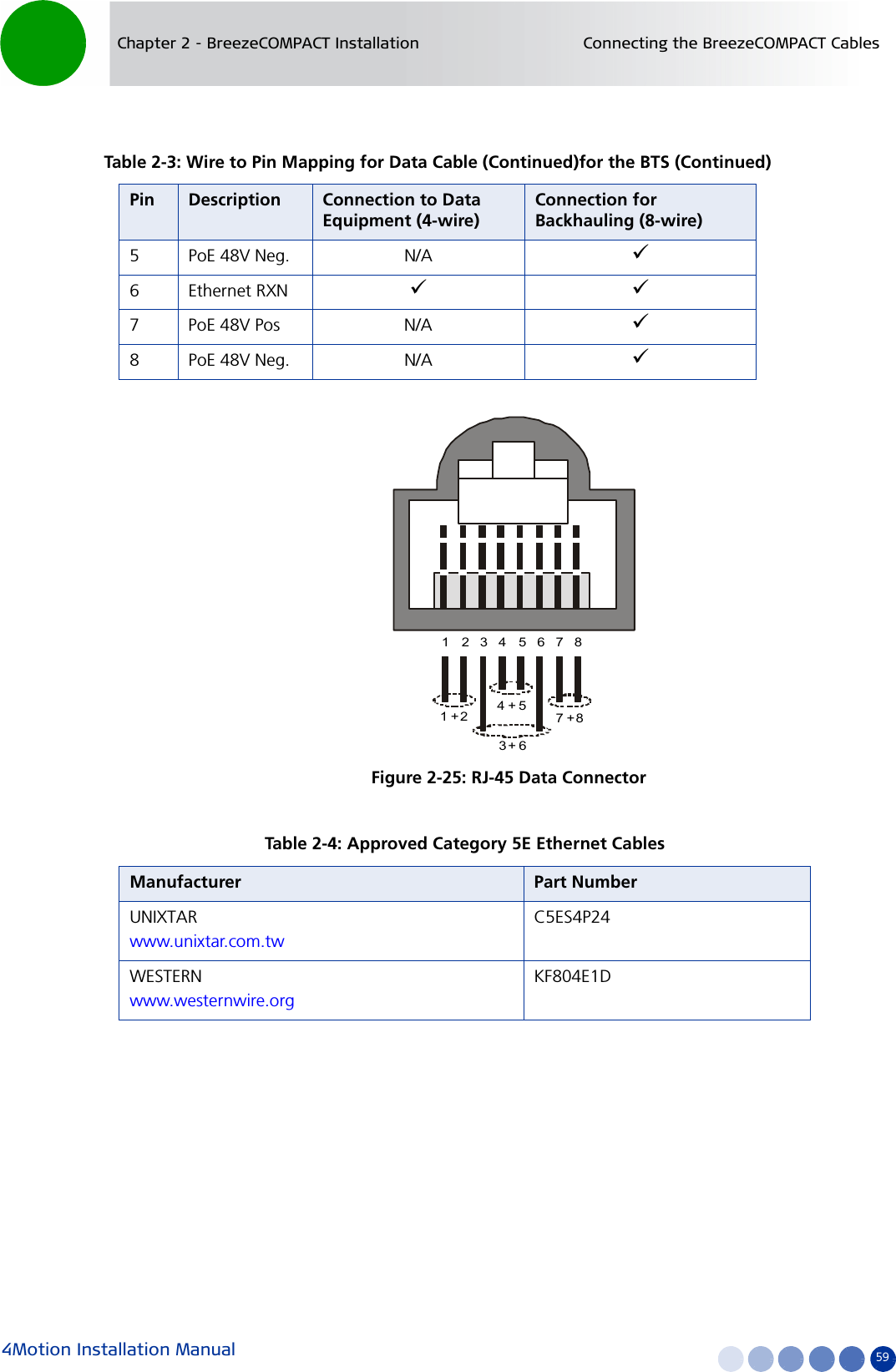
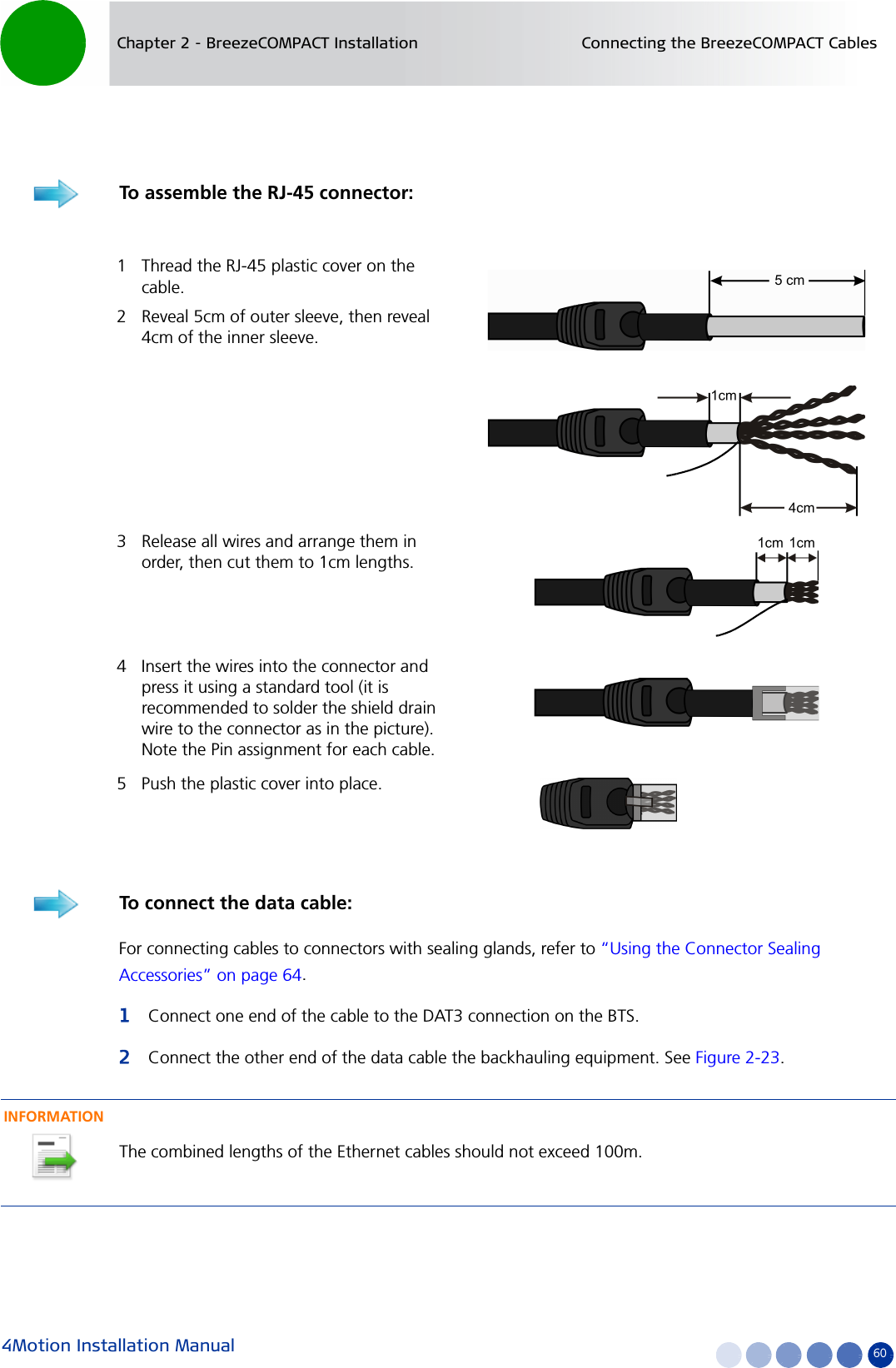
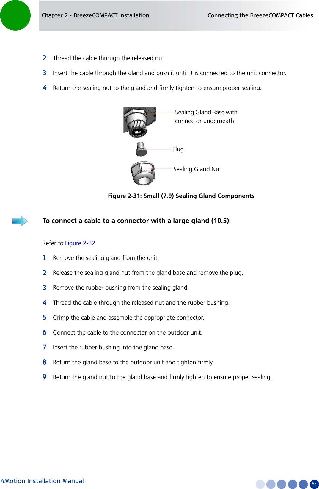
![4Motion Installation Manual 44Chapter 2 - BreezeCOMPACT Installation Pole Mounting with an Attached Antenna1Lift the assembly up the pole using the hook.2For 1”-4” poles attach the other two clamps; For up to 6” poles close the metal bands and fasten.3Fasten all the screws. Apply torques of 80 [Lib*In] = 9 [N*m] to the M8 screws.4Tilt the antenna as necessary and fasten the alignment screws (for wall mount tilting is limited).To mount the assembly on the pole:Figure 2-10: BTS and Attached Antenna Mounted on a 1”-4” Pole](https://usermanual.wiki/Alvarion-Technologies/COMPACT3X.User-manual-part-2/User-Guide-1669926-Page-14.png)