Alvarion Technologies EAP-10AMP Low Power Transceiver and Amplifier Unit User Manual ProbridgeAMP72399 1

Alvarion Ltd. Low Power Transceiver and Amplifier Unit ProbridgeAMP72399 1

Contents

revised users manual
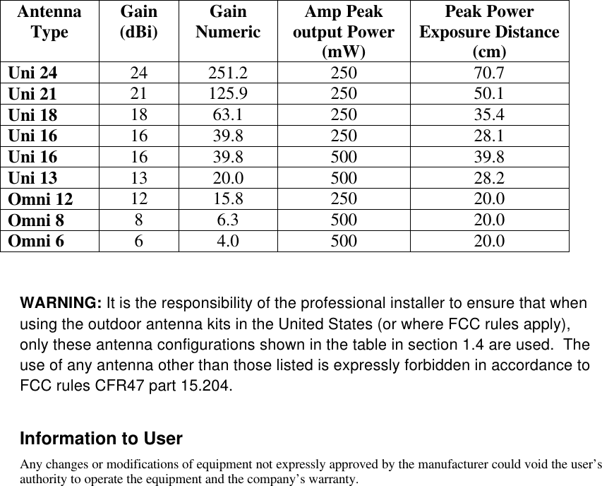
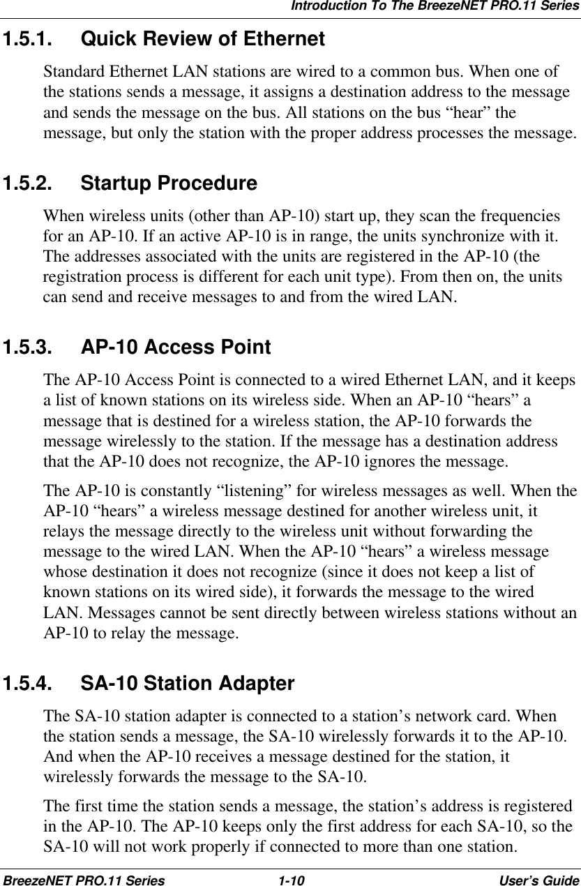
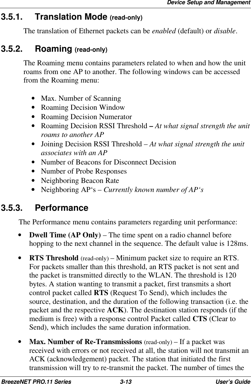
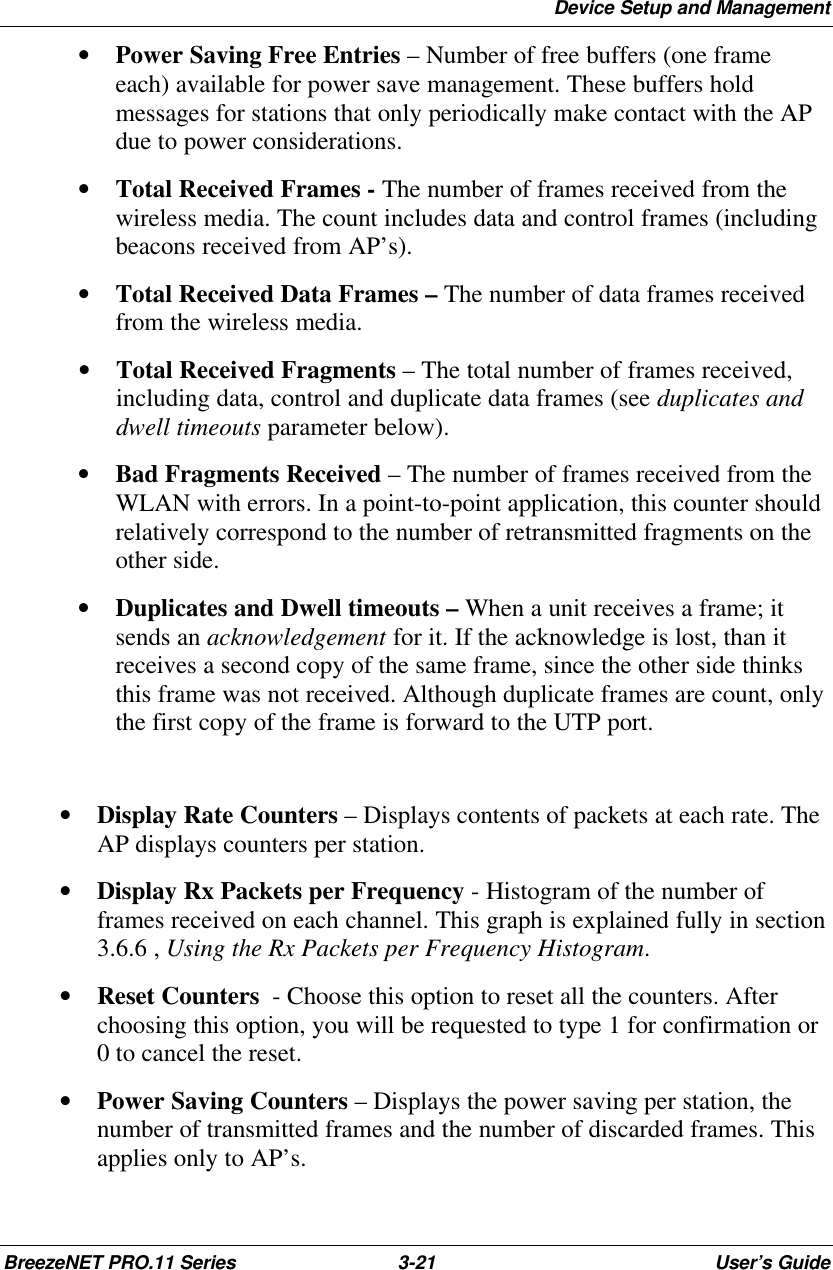
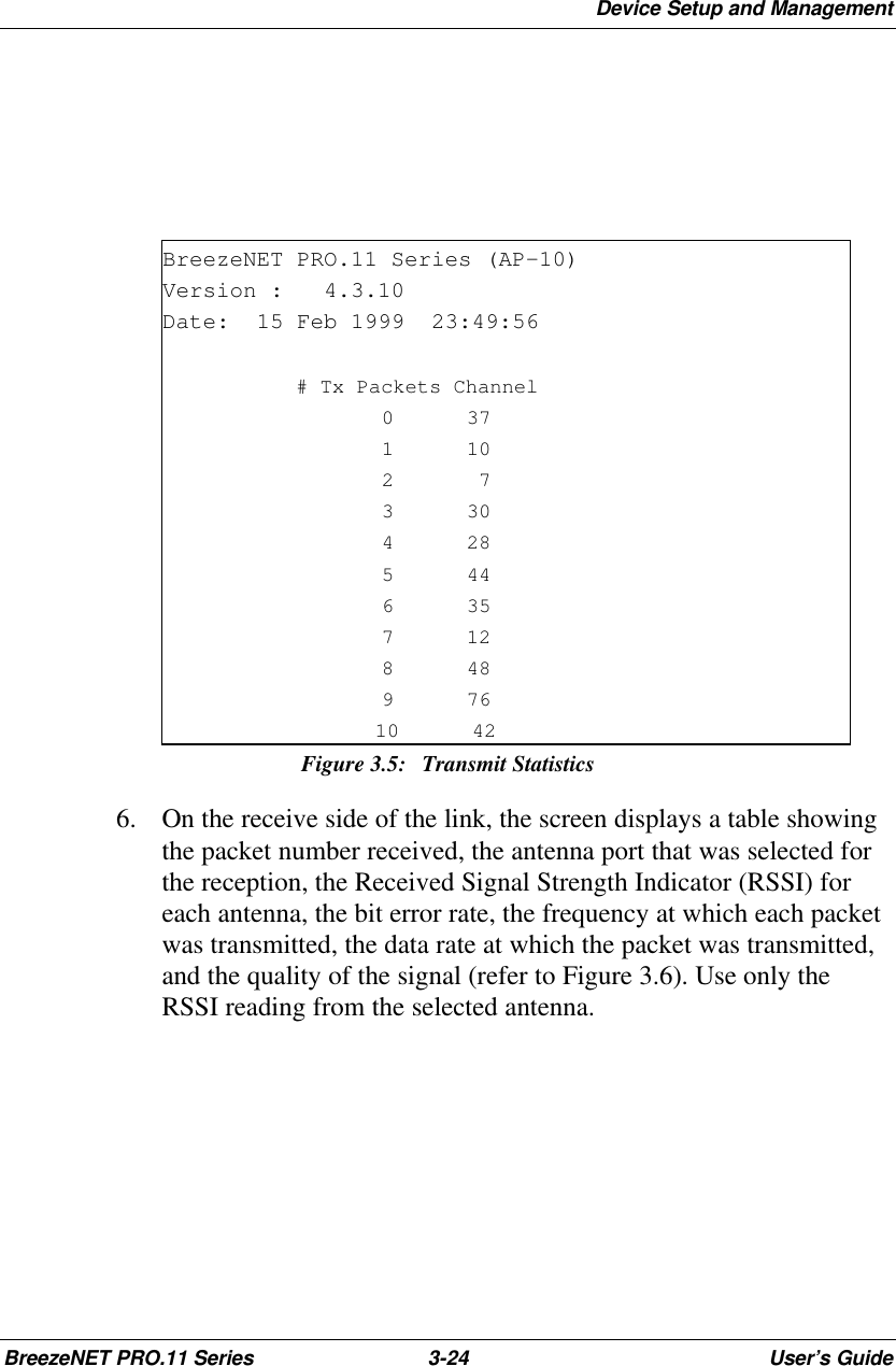
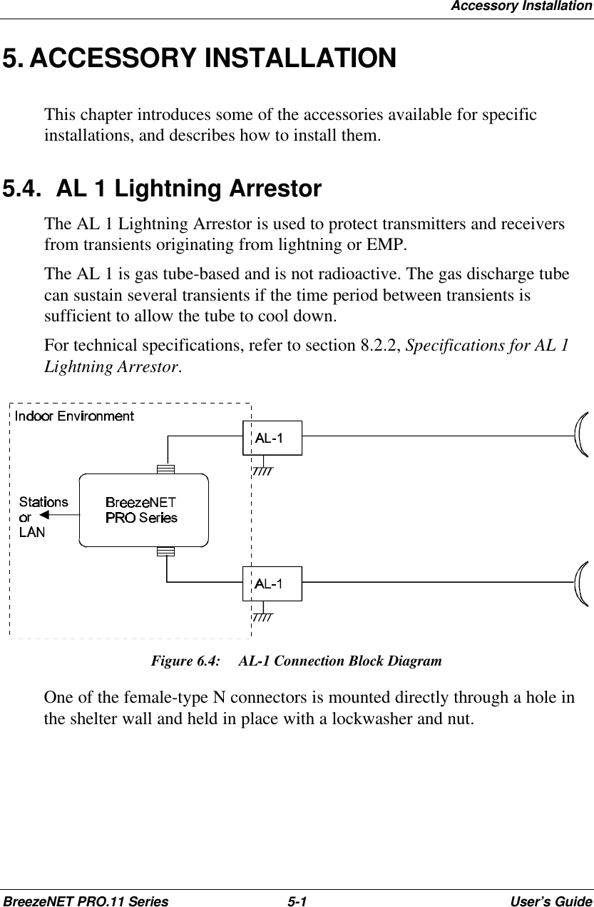
BreezeNET PRO.11 SeriesOutdoor BridgeUser’s Guide(for models using AMP2440-250/500) July, 1999Cat. No. 213034                                                                                                          Revision          2
Disclaimer:  The diagrams in this manual are for illustrative purposes only.  Theyshould not be confused with the transceiver operating in a standalone mode.When these diagrams are in use, the transceiver will be installed in conjunctionwith amp model AMP-2440-250/500 and the antennas listed in Table 1.© 1999 by BreezeCOM Ltd. All rights reserved.No part of this publication may be reproduced in any material form without thewritten permission of the copyright owner.Trade NamesBreezeNET and BreezeLINK are trade names ofBreezeCOM Ltd. Other brand and product names are registered trademarks ortrademarks of their respective companies.
Statement of ConditionsThe information contained in this manual is subject to change without notice. BreezeCOM Ltd. shall not beliable for errors contained herein or for incidental or consequential damages in connection with thefurnishing, performance, or use of this manual or equipment supplied with it.WarrantyIn the following warranty text, “the Company” shall mean:- BreezeCOM Inc., for products located in the USA.- BreezeCOM Ltd., for products located outside the USA.This BreezeNET product is warranted against defects in material and workmanship for a period of one year.During this warranty period the Company will, at its option, either repair or replace products that prove to bedefective.For warranty service or repair, the product must be returned to a service facility designated by the Company.Authorization to return products must be obtained prior to shipment. The buyer shall pay all shipping chargesto the Company and the Company shall pay shipping charges to return the product to the buyer.The Company warrants that the firmware designed by it for use with the unit will execute its programminginstructions when properly installed on the unit. The Company does not warrant that the operation of the unitor firmware will be uninterrupted or error-free.Limitation of WarrantyThe foregoing warranty shall not apply to defects resulting from improper or inadequate maintenance by thebuyer, buyer supplied interfacing, unauthorized modification or misuse, operation outside of theenvironmental specifications for the product, or improper site preparation or maintenance. No other warrantyis expressed or implied. The Company specifically disclaims the implied warranties of merchantability andfitness for any particular purpose.Electronic Emission NoticesThis device complies with Part 15 of the FCC rules, ETSI 300-328, UL, UL/C, TUV/GS,and CE.Operation is subject to the following two conditions:1. This device may not cause harmful interference.2. This device must accept any interference received, including interference that maycause undesired operation.FCC Radiation Exposure StatementThis equipment complies with FCC radiation exposure limits set forth for an uncontrolledenvironment when installed as directed.  This equipment should be installed and operatedwith the minimum distance between any persons body and the antenna as shown below:
AntennaType Gain(dBi) GainNumeric Amp Peakoutput Power(mW)Peak PowerExposure Distance(cm)Uni 24 24 251.2 250 70.7Uni 21 21 125.9 250 50.1Uni 18 18 63.1 250 35.4Uni 16 16 39.8 250 28.1Uni 16 16 39.8 500 39.8Uni 13 13 20.0 500 28.2Omni 12 12 15.8 250 20.0Omni 8 86.3 500 20.0Omni 6 64.0 500 20.0WARNING: It is the responsibility of the professional installer to ensure that whenusing the outdoor antenna kits in the United States (or where FCC rules apply),only these antenna configurations shown in the table in section 1.4 are used.  Theuse of any antenna other than those listed is expressly forbidden in accordance toFCC rules CFR47 part 15.204.Information to UserAny changes or modifications of equipment not expressly approved by the manufacturer could void the user’sauthority to operate the equipment and the company’s warranty.
CONTACTING BREEZECOM TECHNICALSUPPORTShould you need assistance beyond the scope of this guide, please contactyour local BreezeCOM reseller or distributor. If they cannot solve yourproblem, feel free to contact the BreezeCOM Technical SupportDepatrment. The support representatives can assist you in solving anyproblems that cannot be solved by your reseller.When requesting support, please have the following items available:• Configuration of the system, including models of the BreezeCOMequipment used.• Antenna type and cable lengths.• Site information such as, possible radio path problems (trees, machines,and buildings).• Distance between devices.• Configuration, statistic counters, and error messages, as seen on themonitor.• Description of problems encountered.To contact BreezeCOM Technical Support, refer to the Technical Supportpage of the BreezeCOM website: www.breezecom.com
Introduction To The BreezeNET PRO.11 SeriesBreezeNET PRO.11 Series 1-1User’s GuideTABLE OF CONTENTS1. Introduction To The BreezeNET PRO.11 Series ......................................1-41.1. How to Use This Guide .........................................................................1-41.2. BreezeNET PRO.11 Series Features......................................................1-51.3.1. Access Point ..............................................................................1-61.3.4. Workgroup Bridge ...................................................................1-101.4. BreezeNET PRO.11 Functional Description ........................................1-112. Basic Installation........................................................................................2-12.1. Basic Installation Checklist....................................................................2-12.2. Check the Package List..........................................................................2-12.3. Position the Unit....................................................................................2-22.3.1. Additional Considerations When Positioning the Access Point...2-32.4. Connect the Unit to the Power Supply ...................................................2-32.5. Connect the Unit to the Ethernet Port ....................................................2-42.6. Check Unit Functionality using LED indicators.....................................2-52.6.1. Station (SA-10, SA-40) and Bridge (WB-10) LEDs ...................2-52.6.2. Access Point LEDs.....................................................................2-62.6.3. Verifying the Ethernet Connection .............................................2-63. Device Setup and Management..................................................................3-13.1. Accessing and Using Local Terminal Management ...............................3-13.2.  Configuration Screens ..........................................................................3-23.3. Main Menu............................................................................................3-43.4. System Configuration Menu..................................................................3-53.4.1. Station Status .............................................................................3-53.4.2. IP and SNMP Parameters...........................................................3-63.4.3. Wireless LAN (WLAN) Parameters...........................................3-73.4.4. Bridging.....................................................................................3-93.4.5. Station Control.........................................................................3-103.4.6.  Security...................................................................................3-113.5. Advanced Settings Menu.....................................................................3-123.5.1. Translation Mode (read-only)...................................................3-133.5.2. Roaming (read-only) ................................................................3-133.5.3. Performance.............................................................................3-133.5.4. Radio .......................................................................................3-153.5.5. Rate .........................................................................................3-163.5.6. AP Redundancy Support (read-only)........................................3-163.5.7. Maintenance.............................................................................3-163.6. Site Survey Menu................................................................................3-17
Introduction To The BreezeNET PRO.11 SeriesBreezeNET PRO.11 Series 1-2User’s Guide3.6.1.  System Counters .....................................................................3-183.6.2.  Survey Software......................................................................3-223.6.3.  Event Log ...............................................................................3-223.6.4.  Display Neighboring AP’s.......................................................3-223.6.5. Using the Site Survey Software................................................3-233.6.6. Using the Rx Packets per Frequency Histogram .......................3-263.7. Access Control Menu ..........................................................................3-274. Planning and Installing Wireless LANs..............................................5-24.1. System Configurations ..........................................................................5-24.1.1. Single Cell Configuration...........................................................5-34.1.2. Overlapping Cell Configuration .................................................5-74.1.3. Multicell Configuration..............................................................5-94.1.4. Multi-hop Configuration (Relay)..............................................5-114.3. Outdoor Installation Considerations.....................................................5-134.3.1. Site Selection Factors...............................................................5-134.3.2. Rooftop Installation..................................................................5-144.3.3. Antennas for Outdoor Applications ..........................................5-144.3.4. Antenna Seal............................................................................5-164.3.5. Cell Size...................................................................................5-164.3.6. Link Distance...........................................................................5-184.3.7. Using Outdoor Range Tables....................................................5-184.5. Precautions..........................................................................................5-194.5.1. Professional Installers Only......................................................5-194.5.2. Transmit Antenna Gain ............................................................5-194.5.3. Spurious Radio Frequency Emissions.......................................5-194.5.4. Lightning Protection.................................................................5-204.5.5. Rain Proofing...........................................................................5-206. Upgrade Procedure................................................................................6-17. System Troubleshooting.............................................................................7-17.1. Troubleshooting Guide..........................................................................7-17.2. Checking Counters ................................................................................7-37.2.1.  WLAN Counters .......................................................................7-37.2.2.  Ethernet Counters......................................................................7-38. Appendix8.1. Supported MIBs and Traps....................................................................9-18.1.1. Supported MIBs.........................................................................9-18.1.2. Supported Traps.........................................................................9-2
Introduction To The BreezeNET PRO.11 SeriesBreezeNET PRO.11 Series 1-3User’s Guide8.2. Technical Specifications........................................................................9-38.2.1. Specifications for BreezeNET PRO.11 Units..............................9-38.2.5. Specifications for AL 1 Lightning Arrestor ................................9-68.3. Wireless LAN Concepts ........................................................................9-78.4. Radio Signal Propagation ....................................................................9-138.4.1. Introduction..............................................................................9-138.4.2. RF Terms and Definitions........................................................9-138.5. IEEE 802.11 Technical Tutorial...........................................................9-208.5.1. Architecture Components.........................................................9-208.5.2. IEEE 802.11 Layers Description ..............................................9-218.5.3. The MAC Layer.......................................................................9-228.5.4. How Does a Station Join an Existing Cell (BSS)? ....................9-288.5.5. Roaming ..................................................................................9-288.5.6. Keeping Synchronization .........................................................9-298.5.7. Security....................................................................................9-298.5.8. Power Saving...........................................................................9-308.5.9. Frame Types ............................................................................9-318.5.10. Frame Formats.........................................................................9-318.5.11. Most Common Frame Formats.................................................9-368.5.12. Point Coordination Function (PCF) ..........................................9-389.5.13. Ad-hoc Networks.....................................................................9-38
Professional Installation for Model BreezeNET PRO.11/AMP1440 SystemIntended useAll BreezeCOM devices are used to provide high speed data connections to remote networks.The BreezeNET PRO.11/AMP2440 System is not intended nor is it marketed for home use. It isdesigned for use by commercial businesses only.InstallationThe installation of the Model BreezeNET PRO.11/AMP2440 System will be controlled.BreezeCOM will ensure that the professional doing the installation is made aware of therequirements so that the final installation complies with FCC rules. Specifically the installer mustensure that the ERP of the transmitting antenna does not exceed the requirements of paragraph15.247(b) by using an HP 436A power meter and an HP 8481H power sensor.  Power metersthat measures average power must not be used when installing the transmitter, amplifier andantenna combination.It will be explicitly explained to the professional installer that they will install a 250mW or 500mWversion of the amplifier based on the antenna to be used in the installation.  (See attached chart).The output power of the BreezeNET PRO.11/AMP2440 System is limited to 250mW or 500mW,regardless of the loss of cable between the DC injector and the amplifier any length or type of 50ohm coax transmission can be used.Since BreezeNET PRO.11/AMP2440 System are shipped labeled as "BreezeNETPRO.11/AMP2440-250 System" for a 250mW output and a "BreezeNET PRO.11/AMP2440-500System" for a 500mW maximum output, the installer will be aware of the output power of thesystem. Further, all installations of the Model BreezeNET PRO.11/AMP2440 System will requiretopographic analysis, site survey and link budget calculation. Therefore, the system will require aBreezeCOMed trained professional to do the installation.This ensures compliance with the maximum transmitter ERP allowed with the antenna providedas a system.The following statement is in the BreezeNET user's guide (section 5.5.1) and is also supplied asa separate sheet with each device sold:"Professional Installers Only :Detached antennas, whether installed indoors or out, should be installed ONLY by experiencedantenna installation professionals who are familiar with local building and safety codes and,wherever applicable, are licensed by the appropriate government regulatory authorities. Failure todo so may void the BreezeNET product warranty and may expose the end user to legal andfinancial liabilities.""Regulations regarding maximum antenna gains vary from country to country. It is theresponsibility of the end user to operate within the limits of these regulations and to ensure thatthe professional installer is aware of these regulations, as well. "
Marketing and sales channelsBreezeCOM DOES NOT sell direct to end users. BreezeNET PRO.11/AMP2440 System will besold only to BreezeCOM's Authorized Resellers. Those authorized resellers are technicallytrained by BreezeCOM's Engineers periodically and must follow the rules set by BreezeCOM.The BreezeNET/AMP2440 system is designed for Long Range (10-25 miles) applications and itinvolves a complicated mandatory site survey, roof top mast installation, high gain antennas,accurate antenna alignment, etc.  Those activities can be done ONLY by professional installersthat are familiar with the FCC regulations. BreezeCOM do not play in the consumer business atall. We have no resellers in this market and we do not advertise in consumers based publicationsor attend consumer oriented trade shows. The system will be advertised in technical trade showsand magazines.ConclusionBreezeCOM requires professional installation for the Model BreezeNET PRO.11/AMP2440System in-order to provide the highest reliable system possible.  We therefore fully support themandate for professional installation of our complete system.
Introduction To The BreezeNET PRO.11 SeriesBreezeNET PRO.11 Series 1-4User’s Guide1. INTRODUCTION TO THE BREEZENETPRO.11 SERIESThis chapter explains how to use this guide, presents the members of theBreezeNET PRO.11 Series, describes the benefits of BreezeNET PRO.11Wireless LANs, and lists the product specifications.1.1. How to Use This GuideThis User’s Guide contains instructions for overall planning and setting upyour wireless LAN, and provides details of how to install each unit, andhow to install antennas and accessories.This guide contains the following chapters:• Chapter 1 Introduction – Explains how to use this guide and presentsthe members of the BreezeNET PRO.11 Series.• Chapter 2 Basic Installation – Details how to install most BreezeNETPRO.11 Series units.• Chapter 3 Device Setup and Management – Describes how to use thelocal terminal to setup, configure, and manage BreezeNET PRO.11 Seriesunits.• Chapter 4 Planning and Installing Wireless LANs – Providesguidelines and restrictions regarding antenna selection and installation,and includes outdoor antenna range tables.• Chapter 6 Upgrade Procedure – Explains how to perform futureupgrades for BreezeNET PRO.11 Series units using a TFTP application.• Chapter 7 System Troubleshooting – Contains a troubleshooting guidethat provides answers to some of the more common problems which mayoccur when installing and using BreezeNET PRO.11 Series products.• Chapter 8 Appendix – This appendix lists MIBs, and traps supportedby BreezeNET PRO.11 Series products, lists product and attachmentspecifications, provides an overview of the concepts related to wirelessLANs, discusses the concepts and applications of radio signalpropagation relevant to wireless LANs, and introduces the new 802.11standard.
Introduction To The BreezeNET PRO.11 SeriesBreezeNET PRO.11 Series 1-5User’s Guide1.2. BreezeNET PRO.11 Series FeaturesFollowing is a partial list of the features in the BreezeNET PRO.11 Series:• IEEE 802.11 Compliant – All BreezeNET PRO.11 Series units are fullycompliant with the final IEEE 802.11 specification for wireless LANs,and thus support interoperability with other 802.11 compliant vendors.• Fully integrated product family – One high-performance Access Pointfor all products in the series.• Increased Throughput – Up to 2 Mbps data throughput; the best figurein the market!• Translation Bridging – Support for both translation and transparentbridging as defined in the IEEE 802.1.h and RFC 1042 standards.• Seamless Roaming – Network connection is maintained while roamingbetween overlapping coverage areas. Transmission and reception can becontinued while moving at high speeds with no data packet loss orduplication.• Load Sharing – Traffic is equally distributed among all Access Pointsin the area.• Redundancy – In co-located cell environments, upon failure of anAccess Point, stations will switch to other available Access Points.• LED Display – Power, Network Activity, and WLAN Load or SignalQuality LEDs indicate the current status of the unit.• Upgrading – Simple, quick, and free software upgrades via TFTP.• Future-proof Investment – All “infrastructure” items in the PRO.11Series line offer Flash updates.
Introduction To The BreezeNET PRO.11 SeriesBreezeNET PRO.11 Series 1-6User’s Guide1.2.1. Access PointThe Access Point is fully compliant with the IEEE 802.11 wireless LANstandard.The BreezeNET Access Point is a wireless hub that provides access forwireless workstations into wired Ethernet LANs. It also contains a wirelesscoordinating function which enables workstations equipped with a StationAdapter (Station Adapter, Bridge) to communicate with one another insidethe cell coverage area (even if they are not in direct line of sight) via theAccess Point. Any two wireless stations in two different cells cancommunicate through their Access Points.Disclaimer:  This diagram is forillustrative purposes only.  It shouldnot be confused with the transceiveroperating in a standalone mode.When this diagram is in use, thetransceiver will be used inconjunction with amp modelAMP-2440-250/500 and theantennas listed in this manual.Mobile workstations, such as laptops and hand-held devices, can roambetween Access Points that belong to the same Extended Service Set (ESS).In an Extended Service Set, all Access Points have the same ESSID. Whenthe access points are set up so that their coverage areas overlap, users canroam seamlessly from cell to cell. This means that there is no interruption ofnetwork connection when moving from one coverage area to the otherthrough the overlap and is completely transparent to the user and theapplications. The Station Adapters decide when a mobile user becomesdisassociated from one access point and associated with another. Thisprocess is fully transparent, requires no user intervention and involves noloss of data packets.Position multiple access points in locations where heavy network traffic isexpected to create a multicell and increase the aggregate throughputcapacity in areas where it is needed most. The system implements a Load
Introduction To The BreezeNET PRO.11 SeriesBreezeNET PRO.11 Series 1-7User’s GuideBalancing algorithm to divide the stations equally between the available co-located Access Points.The BreezeNET Access Point contains an embedded SNMP agent enablingeffective management by BreezeVIEW or any standard SNMP managementstation. Software upgrades can be downloaded by TFTP protocol via thewired LAN or wireless LAN.1.2.2. Workgroup BridgeThe BreezeNET Workgroup Bridge is a high-speed, wide-range wirelessLAN bridge that provides connectivity to remote Ethernet networks.Figure 1.1:  WB-10D PRO.11 with TwoExternal Antenna Connector PortsDisclaimer:  This diagram is for illustrative purposes only.  It should not beconfused with the transceiver operating in a standalone mode.  When thisdiagram is in use, the transceiver will be used in conjunction with ampmodel AMP-2440-250/500 and the antennas listed in this manual.The Workgroup Bridge communicates with the BreezeNET Access Points ofthe remote LANs effectively creating an extended wireless networkspanning sites situated up to 6 miles apart (in Europe this range is limited byETSI regulations to 2.5 Km.). In this way a central Ethernet LAN may beconnected with one or more branch office LANs.In addition, an island consisting of a Workgroup Bridge together with anAccess Point can work as a relay. Transmissions from the central LAN andfrom the remote LAN are relayed via the island located between them. Thisconfiguration effectively doubles bridge range.
Introduction To The BreezeNET PRO.11 SeriesBreezeNET PRO.11 Series 1-8User’s GuideWorkstations that can be connected to the wireless LAN include PCs, X-Terminals, Digital, SUN, HP, IBM, and Apple computers, and any otherdevice that supports Ethernet. The unit is transparent to the workgroupdevices’ hardware, software, and network operating system.The BreezeNET Workgroup Bridge contains an embedded SNMP agent andsoftware downloading capabilities enabling effective management. Softwareupgrades are downloaded using TFTP protocol via the Ethernet ports or viathe wireless LAN and Access Point.1.3. Extending Range with the AMP2440To extend the range of the AP10-D or WB-10D, the AMP2440-250 orAMP2440-500 is used.  These devices amplify the RF output and receivepower to allow long range connections or connections with longer cableruns.  The diagram below shows a typical installation of the BreezeNet andAMP2440.  (See the addendum at the end of this manual for instructions onhow to install the AMP2440).1.4. Antenna SelectionBREEZECOM AMPLIFIER INSTALLATION DETAILSDC POWERINJECTOR BreezeNetRadio To EthernetHubUTP Cable5ft. LMR-400RF + DCN-Male toN-Male adapterto attach to theN-Female oncableSpecial SMA Right angleMale connectorANTENNAOmni-directional (shown), orGrid or Panel Antennas (not shown)AMP2440 (mounted to mast with U-Bolt)N-Male connectorTransmission LineLMR-400, or other low  loss cable to radio roomMastDripLoopCoax Cable toPole MountedAmplifierBarrel Plug110/220 VACAC Main Power 110/220 VACAC Main Power*Filter is required in the United States when the 24dB grid dishantenna is used in order to comply with FCC emission requirements.N-Male toN-Male adapterto attach to theN-Female oncable
Introduction To The BreezeNET PRO.11 SeriesBreezeNET PRO.11 Series 1-9User’s Guide1.5. BreezeNET PRO.11 Functional DescriptionBreezeNET PRO.11 units add wireless functionality to existing EthernetLANs.The AMP2440 and the BreezeNET radio modem must be professionally installed.Table (1) shows the FCC approved configuration of the AMP2440, BreezeNET Radioand antenna configurations.WARNING:  It is the responsibility of the installer to ensure that when used in theUnited States (or where FCC rules apply), only these configurations are used.  The useof any antenna other than those listed below is expressly forbidden in accordance toFCC rules CFR47 part 15.204.Table (1) FCC Type Acceptance ConfigurationsRadio  Equipment  UNI-2424 dBiGrid  UNI-1818 dBiGrid  UNI-1616 dBiPanel  UNI-1313 dBiPanel  UNI-1111 dBiPanel  OMNI-88 dBiOmni  OMNI-66 dBiOmni  BreezeNETPRO.11 X*X X X X X XBreezeNETPRO.11 withAmp2440-250 X*X X X X X XBreezeNETPRO.11 withAMP2440-500 X X X X X*: External filter (P/N: SPF-1) is required in the United States with the 24dBi gridantenna to comply with FCC spurious emission requirements.  Install this betweenthe amplifier and the antenna.
Introduction To The BreezeNET PRO.11 SeriesBreezeNET PRO.11 Series 1-10 User’s Guide1.5.1. Quick Review of EthernetStandard Ethernet LAN stations are wired to a common bus. When one ofthe stations sends a message, it assigns a destination address to the messageand sends the message on the bus. All stations on the bus “hear” themessage, but only the station with the proper address processes the message.1.5.2. Startup ProcedureWhen wireless units (other than AP-10) start up, they scan the frequenciesfor an AP-10. If an active AP-10 is in range, the units synchronize with it.The addresses associated with the units are registered in the AP-10 (theregistration process is different for each unit type). From then on, the unitscan send and receive messages to and from the wired LAN.1.5.3. AP-10 Access PointThe AP-10 Access Point is connected to a wired Ethernet LAN, and it keepsa list of known stations on its wireless side. When an AP-10 “hears” amessage that is destined for a wireless station, the AP-10 forwards themessage wirelessly to the station. If the message has a destination addressthat the AP-10 does not recognize, the AP-10 ignores the message.The AP-10 is constantly “listening” for wireless messages as well. When theAP-10 “hears” a wireless message destined for another wireless unit, itrelays the message directly to the wireless unit without forwarding themessage to the wired LAN. When the AP-10 “hears” a wireless messagewhose destination it does not recognize (since it does not keep a list ofknown stations on its wired side), it forwards the message to the wiredLAN. Messages cannot be sent directly between wireless stations without anAP-10 to relay the message.1.5.4. SA-10 Station AdapterThe SA-10 station adapter is connected to a station’s network card. Whenthe station sends a message, the SA-10 wirelessly forwards it to the AP-10.And when the AP-10 receives a message destined for the station, itwirelessly forwards the message to the SA-10.The first time the station sends a message, the station’s address is registeredin the AP-10. The AP-10 keeps only the first address for each SA-10, so theSA-10 will not work properly if connected to more than one station.
Introduction To The BreezeNET PRO.11 SeriesBreezeNET PRO.11 Series 1-11 User’s Guide1.5.5. SA-40 Station AdapterThe SA-40 station adapter has four connectors for up to four stations andworks just like the SA-10. As each station connected to the SA-40 sends itsfirst message, each address is registered in the AP-10. The AP-10 keepsonly up to four addresses for each SA-40, so the SA-40 will not workproperly if connected to more than four stations.1.5.6. WB-10 Wireless BridgeAs opposed to the SA-10 and SA-40 that connect directly to stations, theWB-10 wireless bridge connects to a wired Ethernet LAN (Hub). When astation on the WB-10’s LAN sends a message that is not destined for a localstation, the WB-10 wirelessly forwards the message to the AP-10. Andwhen the AP-10 receives a message destined for a station on the WB-10sLAN, the AP-10 wirelessly forwards it to the WB-10. In this way, theWB-10 and AP-10 work together like a standard network bridge.The first time each station on the WB-10’s LAN sends a message, thestation’s address is registered in the WB-10 and the AP-10. The WB-10 andAP-10 can hold all the addresses necessary to support an entire LANconnected to a WB-10.
Basic InstallationBreezeNET PRO.11 Series 2-1User’s Guide2. BASIC INSTALLATIONThe BreezeNET PRO.11 Series is a plug-and-play solution, and the unitsbegin to function when the following basic installation is complete.However, you can adapt the system to your particular needs using the localterminal (see Chapter 3).For a description of various overall system configurations, refer toChapter 4.2.1. Basic Installation ChecklistStandard installation involves the following steps:• Check the Package List.• Position the unit and the antenna in the best location.• Connect the power supply to the unit.• Connect the Ethernet port to the unit.• Check unit functionality using the LED indicators.2.2. Check the Package ListWhen you first open the package, verify that the unit is complete with thefollowing components:• The unit, complete with two RF connectors for use with externalantennas (“D” models).• Quick Installation Guide/Card.• 5V DC power supply transformer.• Mounting bracket for wall or ceiling installations and torque key forantenna connectors (supplied with "D" models).
Basic InstallationBreezeNET PRO.11 Series 2-2User’s GuideThe AP-10 PRO.11 Access Point comes with the following additionalcomponents:• The BreezeNET PRO.11 Series User’s Guide.• A monitor connector cable for connecting the units to a monitor in orderto perform Local Terminal Management functions (see section 3.1).• Proprietary MIB disk for performing remote unit configuration andmonitoring via SNMP (see section 8.1.1).Open the packaging carefully and make sure that none of the items listedabove are missing. Do not discard packaging materials. If, for any reason,the unit is returned, it must be shipped in its original package.2.3. Position the UnitBreezeNET PRO.11 wireless LAN products are robust, trouble-free units,designed to operate efficiently under a wide range of conditions. Thefollowing guidelines are provided to help you position the units to ensureoptimum coverage and operation of the wireless LAN.Metal FurniturePosition the units clear of metal furniture and away from moving objectssuch as metal fans or doors.Microwave OvensFor best performance, position the units clear of radiation sources that emitin the 2.4 GHz frequency band, such as microwave ovens.AntennasFor models with integrated antennas, make sure the antennas are extendedupward vertically in relation to the floor. For models with external antennas,connect the external antennas and RF cable. For information about externalantenna installation, refer to section 4.2
Basic InstallationBreezeNET PRO.11 Series 2-3User’s GuideOutdoor Installation Considerations.Heat SourcesKeep the units well away from sources of heat, such as radiators, air-conditioners, etc.2.3.1. Additional Considerations When Positioning theAccess PointWhen positioning the AP-10 PRO.11 and AP-10DE Access Points, take intoaccount the following additional considerations.HeightInstall the Access Point at least 1.5m above the floor, clear of any highoffice partitions or tall pieces of furniture in the coverage area. The AccessPoint can be placed on a high shelf, or can be attached to the ceiling or awall using a mounting bracket.Central LocationInstall the Access Point in a central location in the intended coverage area.Good positions are:• In the center of a large room.• In the center of a corridor.• At the intersection of two corridors.Many modern buildings have partitions constructed of metal or containingmetal components. We recommend that you install the Access Points on thecorridor ceilings. The radio waves propagated by the BreezeNET PRO.11LAN are reflected along the metal partitions and enter the offices throughthe doors or glass sections.2.4. Connect the Unit to the Power SupplyThe unit operates on a power input of 5V DC, (1200mA , 1500mA peak)supplied by the power transformer included with the unit.
Basic InstallationBreezeNET PRO.11 Series 2-4User’s Guide• Plug the output jack of the power transformer into the DC input socketon the unit. This socket may be located on the rear or side panel of theunit.• Connect the supplied power transformer to a power outlet -110/ 220VAC.2.5. Connect the Unit to the Ethernet Port• Connect one end of a an Ethernet 10BaseT cable (not supplied) to theRJ-45 port on the rear panel of the unit (marked UTP).• Connect the other end of the connector cable to the Ethernet outlet: • When connecting an SA-10 or SA-40 to a PC, use a straight cable. • When connecting an AP-10 or WB-10 to a LAN, use a straightcable. • When connecting an AP-10 or WB-10 to a PC, use a crossed cable. • When connecting an AP-10 to a WB-10, use a crossed cable.
Basic InstallationBreezeNET PRO.11 Series 2-5User’s Guide2.6. Check Unit Functionality using LED indicatorsCheck the unit functionality by using the LEDs on the front panel. Thefollowing tables describe the front panel LEDs for Stations (SA-10, SA-40)and Bridges (WB-10), and for Access Points.2.6.1. Station (SA-10, SA-40) and Bridge (WB-10) LEDsName Description FunctionalityPWR power supply On – After successful power upOff – Power offWLNK WLAN Link On – Unit is synchronized or associated with an APOff – Unit is not synchronized or associated with an APETHR Ethernet activity On – Reception on Ethernet portOff – No reception on Ethernet portQLT Quality of receptionvery low quality reception ornot synchronized with Access Pointless than -81 dBmlow quality reception(usually enabling 1 Mbps traffic)from -81 to -77 dBmmedium quality reception(usually enabling 2 Mbps traffic)from -77 to -65 dBmhigh quality reception(usually enabling 3 Mbps traffic)greater than -65 dBm
Basic InstallationBreezeNET PRO.11 Series 2-6User’s Guide2.6.2. Access Point LEDsName Description FunctionalityPWR power supply On – After successful power upOff – Power offINFR radio interference Off – No interferenceBlinking – Interference PresentETHR Ethernet activity On – Reception of data from Ethernet LAN that is forwarded toWLAN (in reject unknown mode)Off – No reception of data from Ethernet LAN that is forwardedto WLANLOAD WLAN loadNumber of associated stationsno stations1-8 stations9-16 stations17 or more stations2.6.3. Verifying the Ethernet ConnectionOnce you have connected the unit to an Ethernet outlet, verify that theETHR LED on the front panel is blinking. The ETHR LED should blinkwhenever the unit receives LAN traffic.At the other end of the Ethernet link, verify that the LINK indicator is ON.For APs the LINK indicator is located on the attached hub port, and forStation Adapters the LINK indicator is located on the NIC.
Device Setup and ManagementBreezeNET PRO.11 Series 3-1User’s Guide3. DEVICE SETUP AND MANAGEMENTThis chapter explains how to access the local terminal program, and how touse the terminal program to setup, configure, and manage most BreezeNETPRO.11 Series units.The BreezeNET PRO.11 Series is a plug-and-play solution and operatesimmediately after physical installation without any user intervention.However, you can adapt the system to your particular needs using the localterminal. In addition, all products in the series contain an SNMP agent andare configurable remotely via the network.Note: Reset the unit after making configuration changes so that the changes willtake effect.3.1. Accessing and Using Local TerminalManagement⇒⇒   To access Local Terminal Management:1. Use the Monitor cable (supplied with the Access Point) to connectthe MON jack on the rear panel of the unit to the COM port of yourASCII ANSI terminal or PC.2. Run a terminal emulation program (such as HyperTerminal™).3. Set up communication parameters to the following: • Baud Rate: 9600 • Data Bits: 8 • Stop Bits: 1 • Parity: None • Flow Control: NONE • Connector: Connected COM port.4. Press Enter. The main menu appears.
Device Setup and ManagementBreezeNET PRO.11 Series 3-2User’s Guide⇒⇒   To use Local Terminal Management:1. Press an option number to open/activate the option. You may needto press Enter in some cases.2. Press Esc to exit a menu or option.3. Reset the unit after making configuration changes.3.2. Configuration ScreensListed below are the menus, sub-menus, and parameters/options in theterminal program. Default values are listed where applicable. Numbers inthe table below indicate how to reach each option. For example, to reach the1.2.1 IP Address option, start at the main menu, press 1, then 2, and then 1.Menu Sub-Menu Parameter/Option Default Values1. SystemConfiguration 1.1 StationStatus • Unit’s Mode• Unit’s H/W Address• Unit’s WLAN Addr (SA-10/40,WB-10)• Station Status (SA-10-40, WB-10 Only)• Total Number of Associations sincelast reset (SA-10-40, WB-10 Only)• Current Number of Associations (AP)• Maximum Number of Associationssince last reset (AP)• Current Number of Authentications(AP)• Maximum Number of Authenticationssince last reset (AP)1.2 IP andSNMPParameters1.2.1 IP Address1.2.2 Subnet Mask1.2.3 Default Gateway Address1.2.4 SNMP Traps1.2.5 Display Current ValuesNot setNot setNot setEnabled1.3 WirelessLAN (WLAN)Parameters1.3.1 Hopping Sequence  (AP Only)1.3.2 Hopping Set  (AP Only)1.3.3 ESSID1.3.4 Maximum Data Rate1.3.5 Transmit Antenna1.3.6 Mobility1.3.7 Load Sharing1.3.8 Preferred AP (SA-10/40, WB-10 Only)1.3.A Display Current Values1 (FCC standard)1 (FCC standard)ESSID13MbpsUse 2 Antennas*LowDisabled**Not set1.4 Bridging 1.4.1 LAN-WLAN Bridge Mode  (AP Only)1.4.2 Intelligent Bridging Period  (AP Only)1.4.3 IP Filtering1.4.4 Tunneling1.4.5 Broadcast Relaying1.4.6 Unicast RelayingReject Unknown15 secDisabledBothEnabledEnabled
Device Setup and ManagementBreezeNET PRO.11 Series 3-3User’s Guide1.5 StationControl 1.5.1 Reset Unit1.5.2 Load Factory Defaults1.6.Security(Not activated)1.6.1 Authentication Algorithm1.6.2 Default Key ID1.6.3 PreauthenticationA.  WEP Default Key #1B   WEP Default Key #2C.  WEP Default Key #3D.  WEP Default Key #4Open System Key#1DisabledUser defined Userdefined Userdefined Userdefined2. AdvancedSettings 2.1 TranslationMode Enabled2.2 Roaming 2.2.1 Max Number of Scanning2.2.2 Roaming Decision Window2.2.3 Roaming Decision Numerator2.2.4 Roaming Decision RSSI Threshold2.2.5 Jogging Decision RSSI Threshold2.2.6 Number of Beacons for DisconnectDecision2.2.7 Number of Probe ResponsesNeighboring Beacon Rate7010660654Sent every 40dwell times2.3 Performance 2.3.1 Dwell Time  (AP Only)2.3.2 RTS Threshold2.3.3 Max Number of Re-Transmissions2.3.4 Number of Dwells to Re-Transmit2.3.5 Max Multicast Rate2.3.6 Power Saving (Not activated)2.3.7 DTIM Period (Not activated)2.3.8 IP Stack2.3.9 Acknowledge Delay128 millisecs120 bytes121 MbpsDisabled4EnabledRegular2.4 Radio 2.4.1 Hopping Standard2.4.2 Display Site Proprietary Sequences2.4.3 Power Level2.4.4 Carrier Semse Level2.4.5 Carrier Sense Difference LevelUS FCCUser definedHigh50142.5 Rate 2.5.1 Multi – Rate Support2.5.2 Multi – Rate  Decision window Size Enabled32.6 APRedundancySupportEnter New AP Redundancy SupportDecision Period (in seconds) Disabled2.7 Maintenance 2.7.1 Auto Calibration2.7.2 Wait for association Address2.7.3 Japan Call signEnabledWait for update3. Site Survey 3.1 SystemCounters 3.1.1 Display Ethernet and WLANCounters3.1.2 Display Rate Counters3.1.3 Display Rx Packets per Frequency3.1.4 Reset All Counters3.1.5 Power Saving Counters3.2 SurveySoftware 3.2.1 Operation Mode (Rx/Tx)3.2.2 Start Statistics3.2.3 Stop StatisticsRx
Device Setup and ManagementBreezeNET PRO.11 Series 3-4User’s GuideMenu Sub-Menu Parameter/Option Default Values3.3 Event Log 3.3.1 Display Event Log3.3.2 Erase Event Log3.3.3 Event Storage Policy From levelwarning up3.4 DisplayNeighboringAP’s4. AccessControl 4.1 Change Access Rights4.2 Change Installer Password4.3 Show Current Access Right* Option 1.3.5 Transmit Antenna has the default value Use #2 for the SA-40unit only.** Option 1.3.7 Load Sharing has the default value Enabled for the AP-10unit only.3.3. Main MenuBreezeNET PRO.11 Series (SA-10)Version :   4.3.10Date:  15 Feb 1999  23:49:56BreezeNET Monitor==================1 – System Configuration2 – Advanced Settings3 – Site Survey4 – Access ControlSelect option >Figure 3.1: Main MenuPRO.11 Series Unit Model (SA-10, SA-40, WB-10, AP-10)SoftwareVersion
Device Setup and ManagementBreezeNET PRO.11 Series 3-5User’s Guide3.4. System Configuration MenuBreezeNET PRO.11 Series (SA-10)Version :   4.3.10Date:  15 Feb 1999  23:49:56System Configuration menu=========================1 - Station Status2 - IP and SNMP Parameters3 - Wireless LAN Parameters4 – Bridging5 - Station Control6 – SecuritySelect option >Figure 3.2: System Configuration Menu3.4.1. Station StatusStation Status is a read-only sub-menu that displays the current values of thefollowing parameters:• Unit Mode – Identifies the unit’s function. For example, if the unit is anAccess Point, “AP” appears in this field. If the unit is a Station Adapter(SA-10, SA-40) or a WB-10, "SA" appears in this field.• Unit H/W Address – Displays the unit’s unique IEEE MAC address.• Unit WLAN Address (SA or WB) – The address by which the unitassociates. For the SA-10, this is the address of the PC. For the SA-40and WB-10, this is the address of the hardware. This field does notappear when the unit is an AP.• Station Status (SA or WB) – Current status of the station. There arethree options: • Scanning - The station is searching for an AP with which toassociate. • Sync Waiting for Address - (this option is relevant only to the SA-10). The station is synchronized with an AP but has not yet learned
Device Setup and ManagementBreezeNET PRO.11 Series 3-6User’s Guideits WLAN MAC address. The AP does not forward packets to thestation when it is in this mode. • Associated - The station is associated with an AP and has adoptedthe attached PC MAC address (for SA-10) or uses the unit’s H/Waddress (SA-40 and WB-10), and is receiving packets from the LAN.•   AP Address (Station Only) – MAC Address of the AP with which theunit is currently associated.•   Total Number of Associations since last reset  – Total number ofstations currently associated with an AP.•   Current Number of Associations (AP Only) – Total number ofstations currently associated with an AP.•   Maximum Number of Associations since last reset (AP Only – Forstations, this indicates the total number of associations anddisassociations with various AP’s. This is usually an indication ofroaming. When the unit is an AP, this field indicates how many stationsare currently associated with this particular AP.• Current Number of Authentications (AP Only) – The current numberof stations that are authenticated to this AP, including stations that are“pre-authenticated” and not associated to this AP.• Maximum Number of Authentications since last reset (AP Only) –The number of authentications (and “preauthentications”) to this AP;since it was last reset. This number includes stations that weredisauthenticated for different reasons.3.4.2. IP and SNMP ParametersAll BreezeNET PRO.11 units contain IP Host software. This software isused for testing the unit for SNMP management functions and fordownloading software upgrades using the TFTP protocol.• IP Address – IP address of the unit.• Subnet Mask – Subnet mask of the unit.• Default Gateway Address – Gateway address of the unit.• SNMP Traps – Whether this unit sends SNMP traps. If enabled, whenan event occurs, a trap is sent to the defined host address (see section
Device Setup and ManagementBreezeNET PRO.11 Series 3-7User’s Guide8.1.2 for a list of traps). You can configure the host address to which thetraps are sent through SNMP management.• Display Current Values – Displays information concerning the currentstatus of all IP-related items.3.4.3. Wireless LAN (WLAN) ParametersThe WLAN Parameters Menu contains the following options:• Hopping Sequence (AP Only) – Hopping sequence of the unit.A hopping sequence is a pre-defined series of channels (frequencies) thatare used in a specific, pseudo-random order as defined in the sequence.The unit “hops” from frequency to frequency according to the selectedsequence. When more than one AP is co-located in the same area (evenif they are not part of the same network) it is recommended to assign adifferent hopping sequence to each AP.Hopping sequences are grouped in three hopping sets. The hopping setselected in the Hopping Set screen (see next parameter) determineswhich hopping sequences are available in this screen. When setting upmultiple APs in the same site, always choose hopping sequences fromthe same hopping set. This reduces the possibility of collisions on theWLAN.This parameter is set only in AP-10 PRO.11 Access Point. It is notaccessible from any other BreezeNET PRO.11 unit. All other stationslearn it from the Access Point during the association process. Differentco-located WLAN segments should use different hopping sequences.• Hopping Set (AP Only) – Hopping set (between 1 and 3) of the unit.Hopping sequences are grouped in several hopping sets. The hopping setselected in this screen determines which hopping sequences are availablein the Hopping Sequence screen (see previous parameter). Always usethe same hopping set per site.Following is the list of hopping sequences and sets for each country.The default value for all countries is:Hopping Sequence=1, Hopping Set=1.
Device Setup and ManagementBreezeNET PRO.11 Series 3-8User’s Guide• ESSID – ESSID of the unit (up to 32 printable ASCII characters). TheESSID is a string used to identify a WLAN. This ID prevents theunintentional merging of two co-located WLANs. A station can onlyassociate with an AP that has the same ESSID. Use different ESSIDs tosegment the WLAN network and add security.Note: The ESSID is case-sensitive.• Maximum Data Rate – Maximum data rate of the unit. BreezeNETPRO.11 units operate at 1 Mbps, 2 Mbps or 3 Mbps. The unit adaptivelyselects the highest possible rate for transmission. Under certainconditions (compatibility reasons or for range/speed trade-off) you maydecide to limit the use of higher rates.• Transmit Antenna – Which antennas are used for transmission. Duringreception, a BreezeNET PRO.11 unit dynamically selects the antennawhere reception is optimal. In contrast, before transmission the unitselects the antenna from which it will transmit. It usually uses theantenna last used for successful transmission. In models with externalantennas, sometimes only a single antenna is used. In this case, TransmitAntenna should be configured to transmit only from that single antenna.Similarly, models using a booster or an LNA use only a single antennafor transmission. There are three possibilities for configuration:0 Use Two Antennas1 Use Antenna No. 1 only2 Use Antenna No. 2 only• Mobility – BreezeNET PRO.11 stations optimize their roamingalgorithms according to the mobility mode parameter. For example, astationary station is more tolerant of bad propagation conditions. Itassumes that this is a temporary situation and is not caused by the stationchanging position. Initiating a roaming procedure in such a case wouldbe counter-productive. In general, Wireless stations can be used in oneof three mobility modes: • High – For stations that may move at speeds of over 30 km per hour. • Medium – For stations that may move at speeds of over 10 km perhour, but not over 30 km per hour.
Device Setup and ManagementBreezeNET PRO.11 Series 3-9User’s Guide • Low  – For stations that will not move at speeds of over 10 km perhour. Low is the default value. In most cases this is the best choice.• Load Sharing – When installing a Wireless LAN network in a high-traffic environment; you can increase the aggregate throughput byinstalling multiple APs to create co-located cells. When load sharing isenabled, the wireless stations distribute themselves evenly among theAPs to best divide the traffic between the APs.• Preferred AP – AP MAC (Ethernet) address of the preferred AP. Youcan configure a station to prefer a specific AP unit. When the stationpowers up, it will associate with the preferred AP even if the signal fromthat AP is lower than the signal from other APs. The station will roam toanother AP only if it stops receiving beacons from the preferred AP.• Display Current Values – This read-only status screen displays currentWLAN parameters. Press any key to return to the WLAN ParametersMenu.3.4.4. BridgingThe Bridging Menu contains the following options:• LAN to WLAN Bridging Mode (AP Only) – The options are: • Reject Unknown – Type 0 to allow transmission of packets only tostations that the AP knows to exist in the Wireless LAN (behind theWireless Bridge). • Forward Unknown – Type 1 to allow transmission of all packetsexcept those sent to stations that the AP recognizes as being on itswired Ethernet side. When connecting very large networks; it isrecommended to set this parameter to forward unknown.• Intelligent Bridging Period (AP Only) – Intelligent bridging enablessmooth roaming of WB-10 units. When intelligent bridging is enabled,the AP goes into a special bridging mode for a fixed amount of timewhenever a wireless bridge (WB) roams into its area. This mode causesthe AP to forward packets destined for the stations behind the WB-10.Even though, they are known or were learned from the wired side(except that no learning of the wired LAN will take place). Afterwards,the AP will switch back to Reject Unknown bridging mode.
Device Setup and ManagementBreezeNET PRO.11 Series 3-10 User’s GuideThis procedure prevents packets destined for stations behind the bridgefrom getting lost. The value of this parameter is the length of time inseconds that the AP will remain in special mode.• IP Filtering – Whether IP filtering is enabled for the unit. Enable IPFiltering to filter out any other protocol (such as IPX) if you want thatonly IP traffic will pass through the WLAN.• Tunneling – Whether the unit performs Apletalk or IPX tunneling. • Disable Appletalk Tunneling. This parameter allows to disable orenable (default) Appletalk tunneling; if the network contains a mix ofEthertalk1 (ET1) and Ethertalk2 (ET2) stations to ensure smoothcommunications. Be sure to set all units to the same tunnelingsetting.• Disable IPX Tunneling. This parameter allows to disable or enable(default) IPX tunneling; if the IPX protocol is running over yournetwork. Be sure to set all units to the same tunneling setting.• Broadcast Relaying (AP Only) – When Broadcast Relaying is enabled,Broadcast packets originated in WLAN devices are transmitted by theAP back to the WLAN devices, as well as to the LAN. If it is disabled,these packets are sent only to the local wired LAN and are not sent backto the WLAN. Disable Broadcast Relaying only if you know that allBroadcast messages from the WLAN will be destined to the wired LAN.• Unicast Relaying – When Unicast Relaying is enabled, Unicast packetsoriginated in WLAN devices can be transmitted back to the WLANdevices. If this parameter is disabled, these packets are not sent to theWLAN even if they are intended for devices on the WLAN. DisableUnicast Relaying only if you know that all Unicast messages from theWLAN will be destined to the local wired LAN. Note:  Notice that some of the most common internet applications use peer-to-peer traffic, suchas “chat”, ICQ and even internet browsing between a client and a server which are connectedwirelessly on the same subnet. Disabling Broadcast or Unicast relaying will cause suchapplications to become unavailable.3.4.5. Station ControlThe Station Control Menu contains the following options:• Reset Unit – Resets the BreezeNET PRO.11 unit and applies anychanges made to the system parameters.
Device Setup and ManagementBreezeNET PRO.11 Series 3-11 User’s Guide• Set Factory Defaults –When this option is implemented, systemparameters revert back to the original factory default settings. There aretwo options: • Full – All parameters revert to defaults except for the HoppingStandard and Japan Call Sign (if applicable). • Partial – All parameters revert except for the Hopping Standard andJapan Call Sign (if applicable), IP Address, SubNet Mask, DefaultGateway, Hopping Sequence, Hopping Set, ESSID, TransmitAntenna, Acknowledge Delay, Preferred AP, IP Filtering, HoppingStandard, Power Level, Auto Calibration.3.4.6. SecuritySecurity options are not activated yet.The security mechanism involves configuring four different modules:• Authentication Algorithm – This module operates in two modes:• Open System (Default). There is no privacy implemented byauthentication. After synchronization, a station will send arequest for authentication and immediately receive a“successful authentication” message from the AP.(2 frames)• Shared Key authentication (for users with access keys). Thisoption will activate the WEP cryptographic authentication.After synchronization,  a station will send a request forauthentication, the AP will answer with a “challenge text”(ASCII characters), the station will encrypt this text using RC4(not yet implemented) with the encryption key in use and sendthis text back to the AP, the AP will decrypt the receivedmessage and if it matches the original text it will send a“successful authentication” message. (4 frames).The association process will begin only after a successfulauthentication (in either system).• Default Key ID – In order to authenticate, the value of the key usedby the station and the AP must be identical. During theauthentication process a station must notify the AP which key itused to encrypt the challenge text. The station will do this bypassing the number of the current default key it uses. The AP and
Device Setup and ManagementBreezeNET PRO.11 Series 3-12 User’s Guidestation must have the same keys (values).• Preauthentication – During the authentication process the AP isnotifying the other AP’s connected to the Ethernet backbone topreauthenticate the station that has been authenticated to this AP. Itis recommended to use this feature when there is plenty of roamingbetween the AP’s. Preauthentication must be activated on both theAP’s and the Station.• WEP Key#1-4 – These 4 Access Keys must be configured before theycan be used. In this screen you may enter the encryption key. The keyis made of 10 Hex (0-9,A-F) characters. In order to change the unit towork in shared key authentication all four keys must be entered.Entering zeros (0000000000) which is the default for this parameterwill cause the unit to work in open system authentication.3.5. Advanced Settings MenuBreezeNET PRO.11 Series (SA-10)Version :   4.3.10Date:  15 Feb 1999  23:49:56Advanced menu================1 – Translation Mode2 – Roaming3 – Performance4 – Radio5 – Rate6 - AP Redundancy Support7 – MaintenanceSelect option >Figure 3.3: Advanced Settings MenuThe following sections describe the important parameters and relevantinformation in the Advanced Settings Menu. All menu options can beviewed by the Installer; However, the modification of certain parametersfrom this menu, require the Technician access rights level.
Device Setup and ManagementBreezeNET PRO.11 Series 3-13 User’s Guide3.5.1. Translation Mode (read-only)The translation of Ethernet packets can be enabled (default) or disable.3.5.2. Roaming (read-only)The Roaming menu contains parameters related to when and how the unitroams from one AP to another. The following windows can be accessedfrom the Roaming menu: • Max. Number of Scanning • Roaming Decision Window • Roaming Decision Numerator • Roaming Decision RSSI Threshold – At what signal strength the unitroams to another AP • Joining Decision RSSI Threshold – At what signal strength the unitassociates with an AP • Number of Beacons for Disconnect Decision • Number of Probe Responses • Neighboring Beacon Rate •• Neighboring AP‘s – Currently known number of AP‘s3.5.3. PerformanceThe Performance menu contains parameters regarding unit performance:• Dwell Time (AP Only) – The time spent on a radio channel beforehopping to the next channel in the sequence. The default value is 128ms.• RTS Threshold (read-only) – Minimum packet size to require an RTS.For packets smaller than this threshold, an RTS packet is not sent andthe packet is transmitted directly to the WLAN. The threshold is 120bytes. A station wanting to transmit a packet, first transmits a shortcontrol packet called RTS (Request To Send), which includes thesource, destination, and the duration of the following transaction (i.e. thepacket and the respective ACK). The destination station responds (if themedium is free) with a response control Packet called CTS (Clear toSend), which includes the same duration information.• Max. Number of Re-Transmissions (read-only) – If a packet wasreceived with errors or not received at all, the station will not transmit anACK (acknowledgement) packet. The station that initiated the firsttransmission will try to re-transmit the packet. The number of times the
Device Setup and ManagementBreezeNET PRO.11 Series 3-14 User’s Guideunit will try to re-transmit this packet is determined by two parameters inthis menu, Max. Number of Re-Transmissions and Number of Dwells toRe-Transmit. This parameter can be presented as a counter. This counteris decreased each time a re-transmission occurs. It will be the minimumnumber of times a packet will be re-transmitted.• Number of Dwells to Re-Transmit (read-only) – A re-transmission willbe performed after a set number of Dwells. This parameter works inconjunction with the Max Number of Re-Transmissions parameter.• Max Multicast Rate (read-only) – Multicast and Broadcast transmissionsare not yet acknowledged, the chance of error increases. Therefore bydefault, the unit will always transmit broadcasts, multicasts and controlframes in the minimum possible rate, 1Mbps.• Power Saving – This option is not activated yet.There are three modes: •• Disable (Active Mode): The station is Active all the time, uses fullpower. • Enable (Power Save Mode): In this mode the station has two states:Awake state, uses full power. Doze (sleep) state, usesapproximately 5% power. • Enable and test PM bit. In this mode the station will test every frameand check if the power management bit is enabled.Power Management Mechanism:Stations inform AP about their Power Management Mode (Active orPower Save). Stations in Power Save Mode are usually in sleep state. Astation will enter awake state in order to transmit data and also fromtime to time in known intervals (DTIM period).  AP’s maintain a tableindicating the Power Save mode of each associated station. Datadestined for Active Mode stations is sent immediately by AP. Datadestined for Power Save Mode stations is buffered by AP.  EveryBeacon includes TIM (Traffic Identification Map). TIM identifies thestations (by SID) of data buffered in the AP, waiting to be retrieved. Ifa station recognizes its address in the TIM, the station will send a PS-POLL (Power Save Poll) to the AP. In response to this, the AP willforward a data frame buffered for that station.Aging: If a data frame is buffered in the AP more than 50 seconds, it
Device Setup and ManagementBreezeNET PRO.11 Series 3-15 User’s Guidewill be deleted along with all other frames buffered for that station.This process is done every 2 seconds.Notice that although power save mode is set in the AP it will not effectthe APs’ power consumption, but only the handling and management.• DTIM Period (read-only) – This is the number of dwells betweenbroadcast transmissions of messages for stations in power saving mode. Note:  This option is not activated yet.• IP Stack – By default this parameter is enabled. If it is disabled, it willimprove performance, but IP support will not be available.• Acknowledge Delay – Acknowledge delay is designed to increase theperformance in links LONGER THAN 20 KM. This parameter increasesthe ACK timeout in the units, and therefore allows a more efficientoperation. When a BreezeNET unit transmits a certain packet, it waitsfor a pre defined time interval (ACK Timeout) for an ACK packet to bereceived. If the ACK is not received during that interval, the unit willassume the transmission has failed, and will retransmit the packet. Inlinks longer than 20 km, that ACK timeout is not long enough for theACK to arrive to the other side on time, and therefore unnecessaryretransmissions are made, causing the performance to drop. Thisparameter increases the ACK timeout and allows the ACK to arrive tothe other side on time, in links longer than 20 km. Note:  Acknowledge delay must be enabled on both sides of the link, when the distance isgreater than 20 km. If used in links shorter than 20 km, a significant performance drop mayoccur.3.5.4. RadioThe Radio menu contains the following major parameters:• Hopping Standard (read-only) – The Hopping Standard is a set of rulesregarding the radio transmission standard allowed in each country. Unitswill work together only if set to the same hopping standard.• Power level – Output power level at which the unit is transmitting.There are two possibilities, Low (4dBm) or High (17 dBm) at theantenna connector.
Device Setup and ManagementBreezeNET PRO.11 Series 3-16 User’s Guide• Carrier Sense Level (read-only) – Before transmission a station willcheck if the media is free of other transmissions. This parameter is athreshold in RSSI units that determines the sensitivity of the CarrierSense mechanism. Signals with a lower RSSI are considered “noise” andare disregarded by the unit.• Carrier Sense Difference Level (read-only) - Carrier Sense DifferenceLevel refers to a sudden rise of the signal level. This parameter is theminimum rise in RSSI units to be considered a Carrier Sense postitiveresult, in which case the unit will not attempt to transmit. It isrecommended not to change this parameter3.5.5. RateThe Rate menu contains the following relevant parameters:• Multi-Rate Support (read-only) – When this parameter is enabled, theunit will automatically switch to the best transmission rate at any giventime.• Multi-Rate Decision Window Size (read-only) – This parameter indicatesthe number of packets to be used for multi-rate decisions. It isrecommended not to change the value of this parameter.3.5.6. AP Redundancy Support (read-only)When the AP identifies the Ethernet wire connection has been disconnectedover a defined time period; it stops transmitting. The default mode isdisabled (the AP continues transmitting even when the link is discontinued).3.5.7. MaintenanceThe Maintenance menu contains the following major parameters andinformation:• Auto Calibration  – When the unit is started, it performs an internalself-test. Part of this test is automatic calibration of the DC Offset anddeviation pattern. Auto Calibration is not supported in the “DE” models,and it therefore must be disabled for “DE” units.• Wait for Association Address  (SA only) – For the SA-10, theAssociation address is the MAC address of the NIC (Network interface
Device Setup and ManagementBreezeNET PRO.11 Series 3-17 User’s GuideCard) card that the station is connected to through the Ethernet UTP port(usually the Ethernet card of the PC). The station uses the AssociationAddress as its identification in the Wireless Cell (WLAN address).When a station is first connected to an ethernet port, it waits for theAssociation Address update over the Ethernet. You can also have thedevice use its own MAC address (Use Mine) for testing purposes, inwhich case there will not be a proper network connection.3.6. Site Survey MenuBreezeNET PRO.11 Series (SA-10)Version :   4.3.10Date:  15 Feb 1999  23:49:56Site Survey menu================1 - System Counters2 - Survey Software3 – Event Log4 – Display Neighboring AP’sSelect option >Figure 3.4: Site Survey MenuThe Site Survey Menu gives access to the sub-menus necessary to perform aSite Survey that helps you position your units and align their antennas, aswell as perform troubleshooting.The following sections first describe the sub-menus in the Site Surveymenu, and then explain step-by-step how to perform a Site Survey. The SiteSurvey menu contains four sub-menus:• System Counters• Survey Software• Event Log• Display Neighboring AP’s
Device Setup and ManagementBreezeNET PRO.11 Series 3-18 User’s Guide3.6.1. System CountersBreezeNET PRO.11 Series (AP-10)Version :   4.3.10Date:  15 Feb 1999  23:49:56System Counters menu====================1 - Display Ethernet and WLAN Counters2 - Display Rate Counters3 - Display Rx packets per frequency4 - Reset All Counters5 - Power Saving CountersSelect option >Figure 3.4b: Systems Counters MenuThe System counters are a simple yet very efficient tool to monitor, interpretand analyze the Wireless LAN performance.  The counters contain statisticsconcerning Wireless and Ethernet frames.The submenu contains the following options:• Display Ethernet and WLAN Counters – Choose this option todisplay the current value of the Ethernet and Wireless counters. Ethernet Counters Ethernet counters display statistics about the unit’s Ethernet port activity. The unit receives Ethernet frames from its UTP port and forwards them toits internal bridge, which decides whether or not to transmit them to theWireless LAN. The units have a smart hardware filter mechanism whichfilters most of the frames on the LAN, and hardware filtered frames are notcounted. On the other side, frames which where received from the wireless LAN andsome frames generated by the unit (answers to SNMP queries and pingswhich reached to the unit via the UTP port), will be transmitted to the UTPport. Available Counters:
Device Setup and ManagementBreezeNET PRO.11 Series 3-19 User’s Guide• Total Received frames – The total number of frames received from theUTP port. This counter includes both bad and good frames.• Received Bad Frames – The number of frames with errors receivedfrom the UTP port. High values (more than just a few) indicate aproblem in the UTP connection such as a bad UTP cable or hub port.• Received good frames – The number of  good frames (i.e. frames withno errors) received from the UTP port.• Forwarded to the bridge – The number of received frames that wereforwarded to the unit’s internal bridge. This counter should be equal tothe number of good frames unless the internal bridge is overloaded.• Missed Frames – Frames that the unit recognized but failed to read dueto internal bridge overload. This counter should equal zero unless theinternal bridge is overloaded.• Transmitted to Ethernet – The number of frames transmitted by theunit to the UTP port. These mainly include frames that have beenreceived from the Wireless side, but also includes frames generated bythe unit itself. Wireless LAN Counters Wireless counters display statistics about the unit’s Wireless LAN activity. Transmission to the wireless media includes data frames received from theUTP ports, as well as self generated control and management frames. Whena data frame is transmitted, the unit will wait for an acknowledge from thereceiving side. If an acknowledge is not received, the unit will retransmit theframe until it gets an acknowledge (there are no retransmissions for controlframes). If the unit has retransmitted a frame for the maximum number ofretransmissions (refer to section 3.5.3) it will stop re-transmitting the frameand drop this frame. Available Counters:• Total Transmitted Frames – The number of frames transmitted to thewireless media. The count includes the first transmission of dataframes (without retransmissions), and the number of control andmanagement frames.Notice that an AP continuously transmits a control frame calledbeacon in every frequency to which it hops, in order to publish its
Device Setup and ManagementBreezeNET PRO.11 Series 3-20 User’s Guideexistence and keep its associated stations synchronized. Thus, the totaltransmitted frames counter will get high values even if the AP-10 isnot connected to an active LAN.• Total Transmitted Frames (Bridge) - The total number of dataframes transmitted to the wireless media (i.e. frames that were receivedform the UTP port and forwarded to the internal bridge which decidedto transmit them to the wireless media).• Total Transmitted Data Frames – This counter is similar to theabove but counts only data frames. In most BreezeNET PRO.11 units,the number of total transmitted frames and total transmitted frames(bridge) are identical. In the case of the AP, due to the inclusion ofbeacon frames, this number will be higher than that for Totaltransmitted frames.• Frames Dropped (too many retries) – The number of frames whichwere dropped since they were retransmitted for the maximum numberof allowed retransmissions and weren’t acknowledged.• Total Transmitted Fragments – The total number of transmittedframes. The count includes data, control and management frames, andthe number of retransmissions of data frames (for example, if the samedata frame is retransmitted ten times, the count will increase ten times).• Total Retransmitted Fragments – The total number ofretransmissions of data frames (for example, if the same data frame isretransmitted ten times then the count will increase ten times). In apoint-to-point application, this counter should relatively correspond tothe number of bad fragments received on the other side.• Total Tx Errors – The number of transmit errors that have occurred.Currently this counter also includes normal situations where afragment has not been transmitted because the dwell time has elapsed.• Internally Discarded – The number of frames that the AP discardeddue to a buffer overflow. Frame discard will occur mainly when thewireless conditions are bad and the unit is busy re-transmitting framesand doesn’t have time for handling new frames.• Power Saving Aged – The AP buffers frames for stations in a powersaving sleep mode. This counter counts the number of frames droppedby the AP because a station did not wake up for a long time.
Device Setup and ManagementBreezeNET PRO.11 Series 3-21 User’s Guide• Power Saving Free Entries – Number of free buffers (one frameeach) available for power save management. These buffers holdmessages for stations that only periodically make contact with the APdue to power considerations.• Total Received Frames - The number of frames received from thewireless media. The count includes data and control frames (includingbeacons received from AP’s).• Total Received Data Frames – The number of data frames receivedfrom the wireless media.• Total Received Fragments – The total number of frames received,including data, control and duplicate data frames (see duplicates anddwell timeouts parameter below).• Bad Fragments Received – The number of frames received from theWLAN with errors. In a point-to-point application, this counter shouldrelatively correspond to the number of retransmitted fragments on theother side.• Duplicates and Dwell timeouts – When a unit receives a frame; itsends an acknowledgement for it. If the acknowledge is lost, than itreceives a second copy of the same frame, since the other side thinksthis frame was not received. Although duplicate frames are count, onlythe first copy of the frame is forward to the UTP port.• Display Rate Counters – Displays contents of packets at each rate. TheAP displays counters per station.• Display Rx Packets per Frequency - Histogram of the number offrames received on each channel. This graph is explained fully in section3.6.6 , Using the Rx Packets per Frequency Histogram.• Reset Counters  - Choose this option to reset all the counters. Afterchoosing this option, you will be requested to type 1 for confirmation or0 to cancel the reset.• Power Saving Counters – Displays the power saving per station, thenumber of transmitted frames and the number of discarded frames. Thisapplies only to AP’s.
Device Setup and ManagementBreezeNET PRO.11 Series 3-22 User’s Guide3.6.2. Survey SoftwareThe Survey Software sub-menu enables you to align antennas and to assessthe radio signal quality of a point-to-point link. The sub-menu includes thefollowing options:• Operation Mode – When running a Site Survey, set the units on eitherside of the link to either receive (option 1) or transmit (option 2) packets(one unit should be set to transmit and the other to receive). Option 0(Idle mode) is not active at present.• Start Statistics – Press 2 and then press any digit to start Site Survey.• Stop Statistics – Press 3 and then press any key to stop update of SiteSurvey statistics.3.6.3. Event Log• Display Event Log - The last four error messages that the unit displayedsince the last Factory Defaults reset. The Event log stores events in fourlevels of error notifications: Message, Warning, Error, and Fatal.• Erase Event Log – Erase a specific event log.• Event Storage Policy – Defines storage level for the event log. The following are the levels which events are stored in log:0 - Store all events (beginning at message level)1 - Store all events from warning level up2 - Store all events from error level up3 - Store fatal events only3.6.4. Display Neighboring AP’sDisplays neighboring AP’s on the same ESS. The information displayed inthis option refers to the CURRENT or NEIGHBOR AP that the station canhear. The following information is displayed.• The MAC Address of the AP described.• Good or bad frames: The number of frames, out of the total number offrames received from the current AP, that are considered “good or bad”.A frame is considered good or bad; if it was received in an RSSI levelhigher or lower than the value set at the “Roaming Decision RSSI
Device Setup and ManagementBreezeNET PRO.11 Series 3-23 User’s GuideThreshold” parameter (see “Roaming” on section 3.5.2).• Total: The number of frames set as the “Roaming Decision Window” -10 in the example shown above (see “Roaming” on section 3.5.2).• avr RSSI: The average RSSI level of the total number of frames (onlyincludes the frames received without errors).• bcn cnt: (Beacon Count) - How many dwells have passed since the lastbeacon has been received.• Load: The number of stations currently associated with the descried AP.This parameter will be displayed only when “Load Sharing’” (page 24)is Enabled.3.6.5. Using the Site Survey Software⇒⇒ To use the Site Survey Software:1. Roughly, align the antennas on either side of the link beforestarting the Site Survey procedure.2. Verify that the Ethernet cables are disconnected from both units.3. Press 1 to go to the Operation mode screen. Set the units on eitherside of the link to either receive (option 1) or transmit (option 2)packets (one unit should be set to transmit and the other to receive).4. Start the survey by selecting option (2) in the Survey Softwaremenu in both units. When performing a site survey from a stationto an AP (transmitting from the station to the AP), always beginwith the station (select option (2) on the station).5. On the transmit side, a screen appears displaying a table with thenumber of packets and the frequency at which each packet wastransmitted (refer to Figure 3.5). This list is updated continuously.Select option (3) to stop sending packets.
Device Setup and ManagementBreezeNET PRO.11 Series 3-24 User’s GuideBreezeNET PRO.11 Series (AP-10)Version :   4.3.10Date:  15 Feb 1999  23:49:56           # Tx Packets Channel     0      37     1      10     2       7     3      30     4      28     5      44     6      35     7      12     8      48     9      76    10      42Figure 3.5: Transmit Statistics6. On the receive side of the link, the screen displays a table showingthe packet number received, the antenna port that was selected forthe reception, the Received Signal Strength Indicator (RSSI) foreach antenna, the bit error rate, the frequency at which each packetwas transmitted, the data rate at which the packet was transmitted,and the quality of the signal (refer to Figure 3.6). Use only theRSSI reading from the selected antenna.
Device Setup and ManagementBreezeNET PRO.11 Series 3-25 User’s GuideBreezeNET PRO.11 Series (AP-10)Version :   4.3.10Date:  15 Feb 1999  23:49:56#Pack Ant RSSI1 RSSI2 Bit_Err Freq Rate  Quality   58   1   108    91       0   19    3  ###########   59   2   110   112       0   42    3  ###########   60   2    86    88       0   14    3  ########...   61   2   109   112       0   46    3  ###########   62   1   109   107       0   24    3  ###########   63   1   108   106       0   22    3  ###########   64   1   112   108       0   33    3  ###########   65   1   111   107       0   25    3  ###########   66   1   111   111       0   41    3  ###########   67   2   111   110       0   79    3  ###########   68   1   115   111       0   64    3  ###########   69   1   115   111       0   65    3  ###########     70   2   111   111       0   56    3  ###########   71   2   110   111       0   55    3  ###########Figure 3.6: Receive Statistics7. The RSSI is given in arbitrary units. Use the following graph(Figure 3.7) to correlate RSSI to dBm.RSSI  Vs. dBm5060708090100110120130-30 -40 -45 -50 -55 -60 -65 -70 -75 -78 -81 -83 -85RF Level [dbm]RSSI ValueFigure 3.7: RSSI to dBm Graph8. Re-align the antennas until the maximum received signal strengthis obtained. As you align the antennas, you will see that the RSSI(received signal strength indicator) continually increases until itreaches a certain level after which the RSSI begins to decrease.This is the maximum attainable RSSI level indicating optimumreceive antenna alignment.
Device Setup and ManagementBreezeNET PRO.11 Series 3-26 User’s Guide9. Switch the functions of either side of the link (set the transmit unitto receive and the receive unit to transmit) and repeat the procedureto check the link from the opposite direction.3.6.6. Using the Rx Packets per Frequency HistogramUse the Display Rx Packets per Frequency option to see a histogram of thenumber of frames received on each channel.BreezeNET PRO.11 Series (AP-10)Version :   4.3.10Date:  15 Feb 1999  23:49:56Max = 187Min = 112                                                                           #     #                      #            #   #                             # #   #              ####    ###          # # #  #   # ##  #  ## # #  ##    # #   ## ##  #   ## ######## ######   # ######## # ### ##  #  ## # #  ## # ######### ## ######################################################### #####################################################################################^         ^         ^         ^         ^         ^         ^         ^2       +10       +20       +30       +40       +50       +60       +70Hit any key to return >Figure 3.8: Display Rx Packets per FrequencyEach point of the histogram line corresponds to a frequency. The basefrequency appears at the far left, and gradations are marked in steps of tenalong the line. A hash represents each packet received on a given frequency(#). The Max and Min values indicate the highest and lowest number offrames received across all frequencies. This graph is very useful for tracking
Device Setup and ManagementBreezeNET PRO.11 Series 3-27 User’s Guideinterference. Frequencies with low numbers of packets received probablyhave more interference than other frequencies.3.7. Access Control MenuAccess Control functions enable the System Administrator or Installer tolimit the access to the Local Terminal Maintenance setup and configurationmenus.BreezeNET PRO.11 Series (AP-10)Version :   4.3.10Date:  15 Feb 1999  23:49:56Access Control menu===================1 - Change Access Rights2 - Change Installer PasswordS - Show Current Access RightSelect option >Figure 3.9:  Access Control MenuThe Access Control menu includes the following options:• Change Access Rights – This screen determines the level of accessrights to the BreezeNET PRO.11 unit’s setup and configuration menus.When the unit is first installed, the default setting is option (1), Installerand the default password is “user”: • User – The Local Terminal Management menus are read-only for auser who does not possess the correct password. The ESSID andsecurity parameters are hidden by asterisks (*) at this level. • Installer – The installer has access to configure all requiredparameters in the system configuration menu, as well as some of the
BreezeNET PRO.11 Series 3-28 User’s Guideadvanced settings. Access is password-protected. Afterconfiguration, the installer should change access rights to option (0),User. The installer can also change the installer password (see nextparameter). • Technician – Only a Certified BreezeCOM Engineer possessing thecorrect password can select this option to configure all theparameters and settings.• Change Installer Password – Type in the new password according tothe directions on screen. This screen changes the installer password toprevent unauthorized persons from making any changes in systemconfiguration and setup. The password is limited to eight printableASCII characters. This option is not available at User level.• Show Current Access Right – This read-only screen presents thecurrent access right configuration. Important: If you change the Installer password do not forget it, or you will beunable to change the unit's access rights.
Planning and Installing Wireless LANsBreezeNET PRO.11 Series 4-2User’s Guide4. PLANNING AND INSTALLINGWIRELESS LANSThis chapter describes various possible system configurations, lists points toconsider when performing indoor and outdoor installations, presentsguidelines and restrictions regarding external antenna installation. It alsodescribes some antennas that work well with BreezeNET PRO.11 units.4.1. System ConfigurationsThis chapter describes various wireless LAN configurations, and how to setthem up:• Single Cell Configuration – The wireless LAN consists of an AccessPoint and the wireless workstations associated with it.• Overlapping Cell Configuration – The wireless LAN consists of twoor more adjacent Access Points whose coverage slightly overlaps.• Multicell Configuration – The wireless LAN consists of several AccessPoints installed in the same location. This creates a common coveragearea that increases aggregate throughput.• Multi-Hop Configuration – The wireless LAN contains AP-WB pairsthat extend the range of the wireless LAN.Many wireless LANs contain several of these configurations at differentpoints in system. The Single Cell configuration is the most basic, and theother configurations build upon it.
Planning and Installing Wireless LANsBreezeNET PRO.11 Series 4-3User’s Guide4.1.1. Single Cell ConfigurationA basic BreezeNET cell consists of an Access Point and the wirelessworkstations associated with it. You can convert most workstations (PCs,X-Terminals, Apple, Digital, SUN, HP, IBM and others) that are equippedwith an Ethernet network interface card (NIC) to wireless workstationssimply by connecting a BreezeNET SA-10 PRO.11 Station Adapter.There are three types of Single Cell Configuration:• Point-to-Point• Point-to-Multipoint• Mobile ApplicationsEach type is explained in the following sections.4.1.1.1 Point-to-PointPoint-to-Point installations (refer to Figure 5.1) require directional antennasat either end of the link. To select the best antenna for a specific application,consider the following factors:• Distance between sites• Required throughput• Clearance between sites• Cable length.Refer to the range tables (section 4.2.7) to determine the best combination ofantennas for your application.4.1.1.2 Point-to-MultipointPoint-to-Multipoint applications consist of one or more APs at the centralsite and several remote stations and bridges (SA-10, SA-40, WB-10). In thiscase, use an Omni antenna with the Access Point because of its 360°radiated pattern. Ιn the United States, the Omni-8 antenna (which also has a360° radiated pattern but has a wider range) can also be used. The Omni-8antenna comes with 20ft. of low loss cable and a mast mount bracket forrooftop installations.
Planning and Installing Wireless LANsBreezeNET PRO.11 Series 4-4User’s GuideThe remote units should use directional antennas aimed in the direction ofthe AP’s antenna(s).4.1.1.3 Mobile ApplicationsIn mobile applications, station orientation changes continuously. In order tomaintain connectivity throughout the entire coverage area, most mobileapplications require omni-directional antennas for both Access Points andwireless stations. In a motor vehicle, for example, you can install an SA-10in the cabin, and mount the antennas on the roof.4.1.1.4 Extending the LAN with WLAN BridgingThe figures below demonstrate how the WB-10 can be used to extend aregular network with a wireless link.Disclaimer:  This diagram is for illustrative purposes only.  It should not beconfused with the transceiver operating in a standalone mode.  When thisdiagram is in use, the transceiver will be used in conjunction with ampmodelAMP-2440-250/500 and the antennas listed in this manual.Figure 5.1:  Connecting Remote Offices to Main Office Network
Planning and Installing Wireless LANsBreezeNET PRO.11 Series 4-5User’s GuideThe WB-10 PRO.11 also enables connectivity between a wireless LAN andindividual workstations or workgroups located outside the LAN. TheWB-10 PRO.11 enables these wireless stations in its coverage area tocommunicate with the wireless LAN and gain access to all of the networkresources such as file servers, printers and shared databases.Figure 5.2:  Wireless Bridging Between Two or More Wireless LAN Segments4.1.1.5 Setting Up a Single BreezeNET Cell⇒⇒ To set up a single BreezeNET cell:1. Install the Access Point (refer to section 2, Basic Installation). Besure to position the Access Point as high as possible.Note:  It is not necessary at this point to connect the Access Point to an Ethernetbackbone, since Access Points continuously transmit signals (beaconframes) whether they are connected to an Ethernet backbone or not.2. Install a Station Adapter (refer to section 2, Basic Installation).3. Check the LED indicators of the front panel of the Station Adapter,to check signal strength.4. Make any necessary adjustments, for example:
Planning and Installing Wireless LANsBreezeNET PRO.11 Series 4-6User’s Guide• Adjust the antennas• Adjust the location of the Station Adapter• Adjust the location of the Access Point5. Proceed to setup the other workstations.Figure 5.3: Single Cell ConfigurationDisclaimer:  This diagram is for illustrative purposes only.  It should not beconfused with the transceiver operating in a standalone mode.  When this diagramis in use, the transceiver will be used in conjunction with amp modelAMP-2440-250/500 and the antennas listed in this manual.
Planning and Installing Wireless LANsBreezeNET PRO.11 Series 4-7User’s Guide4.1.2. Overlapping Cell ConfigurationWhen two adjacent Access Points are positioned close enough to each other,a part of the coverage area of Access Point #1 overlaps that of Access Point#2. This overlapping area has two very important attributes:• Any workstation situated in the overlapping area can associate andcommunicate with either Access Point #1 or Access Point #2.• Any workstation can move seamlessly through the overlapping coverageareas without losing its network connection. This attribute is called,Seamless Roaming.Figure 5.4: Three Overlapping Cells⇒⇒ To set up overlapping BreezeNET cells:1. Install an Access Point (refer to section 2, Basic Installation). Besure to position the Access Point as high as possible.2. Install the second Access Point so that the two are positioned closertogether than the prescribed distance (refer to section Error!Reference source not found.).3. To allow roaming, configure all Access Points and stations adaptersto the same ESSID.4. To improve collocation and performance, configure all AccessPoints to different hopping sequences of the same hopping set.
Planning and Installing Wireless LANsBreezeNET PRO.11 Series 4-8User’s Guide5. Install a Station Adapter or SA-PCR Card on a workstation.6. Position the wireless workstation approximately the same distancefrom the two Access Points.7. Temporarily disconnect the first Access Point from the powersupply. Verify radio signal reception from the first Access Point.View the LED indicators of the front panel of the Station Adapter,or the Site Survey application of the SA-PCR Card, to check signalstrength of the first Access Point.8. Disconnect the second Access Point from the power supply and re-connect the first Access Point. View the LED indicators of the frontpanel of the Station Adapter, or the Site Survey application of theSA-PCR Card, to check signal strength of the second Access Point.7. If necessary, adjust the distance between the Access Points so thecoverage areas overlap.8. Continue setting up overlapping cells until the required area iscovered.Note:  It is not necessary at this point to connect the Access Points to an Ethernetbackbone, since Access Points continuously transmit signals (beaconframes) whether they are connected to an Ethernet backbone or not.
Planning and Installing Wireless LANsBreezeNET PRO.11 Series 4-9User’s Guide4.1.3. Multicell ConfigurationAreas congested by many users and a heavy traffic load may require amulticell structure. In a multicell structure, several Access Points areinstalled in the same location. Each Access Point has the same coveragearea, thereby creating a common coverage area that increases aggregatethroughput. Any workstation in the overlapping area can associate andcommunicate with any Access Point covering that area.⇒⇒ To set up a BreezeNET multicell:1. Calculate the number of Access Points needed as follows: Multiplythe number of active users by the required throughput per user, anddivide the result by 1.5Mbps (net throughput supported bycollocated Access Points). Consider the example of 5 activestations, each requiring 0.5 Mbps throughput. The calculation is(5*.5)/1.5=1.6. Two Access Points should be used. This method isaccurate only for the first few Access Points.The aggregate throughput of the common coverage area is equal tothe number of co-located Access Points, multiplied by thethroughput of each individual Access Point, minus a certain amountof degradation caused by the interference among the differentAccess Points.2. Install several Access Points in the same location a few metersfrom each other so they cover the same area. Be sure to position theAccess Points as high as possible.3. To allow roaming and redundancy, configure all Access Points andstations adapters to the same ESSID.4. To improve collocation and performance, configure all AccessPoints to different hopping sequences of the same hopping set.5. Install Station Adapters or SA-PCR Cards on workstations.6. Make sure that the Load Sharing option is activated. Stations willautomatically associate with an Access Point that is less loaded andprovides better signal quality.
Planning and Installing Wireless LANsBreezeNET PRO.11 Series 4-10 User’s GuideNote:  It is not necessary at this point to connect the Access Points to an Ethernetbackbone, since Access Points continuously transmit signals (beaconframes) whether they are connected to an Ethernet backbone or not.Figure 5.5: Multicell Configuration
Planning and Installing Wireless LANsBreezeNET PRO.11 Series 4-11 User’s Guide4.1.4. Multi-hop Configuration (Relay)When you want to connect two sites between which a line-of-sight does notexist, an AP-WB pair can be positioned at a third location where line-of-sight exists with each of the original locations. This third location then actsas a relay point.In areas where a wired LAN backbone is not available, another AP can beadded to the AP-WB relay to distribute a wireless backbone. In this way, therange of a wireless system can be extended.System configuration is as follows:⇒⇒ To set up a BreezeNET multi-hop cell:1. Install an AP at the main office (refer to section 2, BasicInstallation).2. Install a WB at the remote site (refer to section 2, BasicInstallation).3. Install an AP-WB pair in a high location that has a clear line ofsight to both the main office and the remote site. Many AP-WBpairs can form a chain.4. When an AP and WB communicate over the wireless LAN, setthem both to the same ESSID. For example, set the AP of the mainoffice and the WB of the first AP-WB relay pair to the sameESSID. Also, set the AP of the last AP-WB relay and the WB ofthe remote site to the same ESSID; this ESSID should be differentfrom the first ESSID.Another option is to use one ESSID, and to set the Preferred APparameter of each WB to its paired AP (refer to section 3.4.3). Thisoption allows stations to roam between the sites.5. As usual, make sure that the hopping sequence of the Access Pointsare different.
Planning and Installing Wireless LANsBreezeNET PRO.11 Series 4-12 User’s GuideFigure 5.6: Multihop Configuration6. If desired, an additional AP may be added at the main office andremote site, and between each AP-WB pair to provide wirelessLANs at those points (see illustration).Figure 5.7: Advanced Multihop Configuration7. Install Station Adapters or SA-PCR Cards on workstations (refer tosection 2, Basic Installation).
Planning and Installing Wireless LANsBreezeNET PRO.11 Series 4-13 User’s Guide4.2. Outdoor Installation ConsiderationsThis chapter describes various considerations to take into account whenplanning an outdoor installation including site selection, antenna alignment,antenna diversity, antenna polarization, antenna seal, and cell size.4.2.1. Site Selection FactorsWhen selecting a location for external antennas, remember to take intoconsideration the following guidelines:• Minimum distance between sites• Maximum height above the ground• Maximum line of sight clearance• Maximum separation between antennas (diversity option)Path of Clearest PropagationA propagation path is the path that signals traverse between the antennas ofany two bridges. The “line” between two antenna sites is an imaginarystraight line which may be drawn between the two antennas. Any obstaclesin the path of the “line” degrade the propagation path. The best propagationpath is, therefore, a clear line of sight with good clearance between the“line” and any physical obstacle.Physical ObstaclesAny physical object in the path between two bridges can cause signalattenuation. Common obstructions are buildings and trees. If a bridge’santenna is installed indoors, the walls and/or windows between the two sitesare physical obstructions. If the antenna is positioned outdoors, anybuildings or other physical structure such as trees, mountains or othernatural geographic features higher than the antenna and situated in the pathbetween the two sites can constitute obstructions.Install indoor antennas as close as possible to a window (or wall if awindow is not accessible) facing the required direction. Avoid metalobstacles such as metal window frames or metal film anti-glare windows inthe transmission path. Install outdoor antennas high enough to avoid anyobstacles which may block the signal.
Planning and Installing Wireless LANsBreezeNET PRO.11 Series 4-14 User’s GuideMinimal Path LossPath loss is determined mainly by several factors:• Distance between sitesPath loss is lower and system performance better when distancesbetween sites are shorter.• ClearancePath loss is minimized when there exists a clear line of sight. Thenumber, location, size, and makeup of obstacles determine theircontribution to path loss.• Antenna heightPath loss is lower when antennas are positioned higher. Antenna heightis the distance from the imaginary line connecting the antennas at thetwo sites to “ground” level. “Ground” level in an open area is the actualground. In dense urban areas, “ground” level is the average height of thebuildings between the antenna sites.4.2.2. Rooftop InstallationWarning: Rooftop antenna installations are extremely dangerous! Incorrectinstallation may result in death, serious injury and/or damage. Suchinstallations should be performed by professional antenna installersonly!Rooftop installations offer several advantages:• Increased antenna range.• Less obstacles in path.• Improved performance due to greater height.• Reduced multipath problems.4.2.3. Antennas for Outdoor ApplicationsThe BreezeNET PRO.11 Series can be used in point-to-point or point-to-multipoint configurations.
Planning and Installing Wireless LANsBreezeNET PRO.11 Series 4-15 User’s Guide4.2.3.1 Point-to-PointA point-to-point link is based on the use of one Access Point with externalantennas and one adapter (SA-10/40D, WB-10D). The AP and the WB mustbe equipped with one or two directional antennas. The necessary antennagain depends on the required range and performance.4.2.3.2 Point-to-MultipointSetting up a point-to-multipoint link requires the use of an AP-10Dequipped with omni-directional antennas and a remote WB-10D (or SA-10/40D) equipped with high-gain directional antennas.4.2.3.3  Antenna AlignmentLow gain antennas do not require alignment due to their very wide radiationpattern. High gain antennas have a narrow beamwidth necessitating analignment procedure in order to optimize the link.Check antenna alignment by using the LED indicators on the front panel ofwhichever adapter is used in the link (WB-10D or SA-10/40D). These LEDindicators provide indication of reception quality.⇒⇒ To perform antenna alignment: 1. Assemble antennas according to the assembly instructions includedwith the antenna set. 2. Mount the antennas as high as possible. 3. Connect the coaxial cable to the AP at the main site. 4. Connect the coaxial cable to the WB (or SA) at the remote site. 5. Power on the AP and the WB (or SA). 6. Synchronize the units by aligning the antennas manually until theWLNK indicator LED on the front panel of the wireless Bridgeand/or Station Adapter illuminates. 7. Align antennas at the main and remote sites until maximum signalquality is obtained. (Check QLT LEDs on the front panel of theStation Adapter and the wireless Bridge.)
Planning and Installing Wireless LANsBreezeNET PRO.11 Series 4-16 User’s GuideIf the received signal quality is lower than expected for this antenna/rangecombination, change antenna height and verify RF cables connections.4.2.3.4  Antenna DiversityIn applications where no multipath propagation is expected, a single antennais sufficient to ensure good performance levels. However, in cases wheremultipath propagation exists, BreezeCOM recommends that two antennasbe used. This takes advantage of space diversity capabilities. By using twoantennas per unit, the system can select the best antenna on a per-packetbasis (every several milliseconds).Multipath propagation is to be expected when there are potential reflectorsbetween the main and remote sites. These reflectors may be buildings ormoving objects such as airplanes and motor vehicles. If this is the case, theradio signal does not travel in a straight line, but is reflected or deflected offof the object, creating multiple propagation paths.When installing a single antenna, modify the transmit antenna option toeither antenna 1 or antenna 2, according to the antenna being used (refer tosection 3.4.3).  Note:  Only antennas from Table 1 FCC Type AcceptanceConfigurations can be used.4.2.3.5  Antenna PolarizationAntenna polarization must be the same at either end of the link. In mostapplications, the preferred orientation is vertical polarization. Above-groundpropagation of the signal is better when it is polarized vertically. To verifyantenna polarization, refer to the assembly instructions supplied with theantenna set.4.2.4. Antenna SealWhen using outdoor antennas, you must seal the antenna connectors againstrain. Otherwise the antennas are not suitable for use in outdoor installations.4.2.5. Cell SizeCell size is determined by the maximum possible distance between theAccess Point and the Station Adapter, usually related to point-to-multipointinstallations using external antennas. For open outdoor areas with anunobstructed line of sight between the Access Point and the BreezeNET
Planning and Installing Wireless LANsBreezeNET PRO.11 Series 4-17 User’s GuidePRO.11 workstation, the suggested maximum distance between AccessPoint and workstation is:Standard AP-10 PRO.11.........................700m (2000 ft.)4.2.6. Link DistanceLink distance is the maximum distance between the AP and the stationadapter, usually related to point-to-point installations using externalantennas. For open outdoor areas with an unobstructed line of sight betweenthe Access Point and the wireless bridge, the suggested maximum distanceis:AP-10D PRO.11 with external antennas .......up to 10Km (7 miles) in the USANote:  The maximum distance of 10Km/7 miles is achieved using 24 dBi antennas.4.2.7. Using Outdoor Range TablesOutdoor installations must have a clear line-of-sight. Solid obstacles such asbuildings or hills prevent the establishment of a link. Partial obstacles suchas trees or traffic can reduce range. Extending coaxial cables can cause anincrease in assembly signal loss and a reduction in range.The ranges in the following tables are attained under good propagatingconditions when using the standard cables supplied in the antenna set.Actual ranges may vary due to specific multipath and interferenceconditions.For specific range guidelines and information about extending cables,consult your local dealer or BreezeCOM central offices.Ranges are subject to change without notice.
Planning and Installing Wireless LANsBreezeNET PRO.11 Series 4-18 User’s Guide4.3. Precautions4.3.1. Professional Installers OnlyCaution:  Detached antennas, whether installed indoors or out, should beinstalled ONLY by experienced antenna installation professionals whoare familiar with local building and safety codes and, whereverapplicable, are licensed by the appropriate government regulatoryauthorities.Failure to do so may void the BreezeNET Product Warranty and mayexpose the end user to legal and financial liabilities. BreezeCOM andits resellers or distributors are not liable for injury, damage orviolation of government regulations associated with the installation ofdetached antennas.4.3.2. Transmit Antenna GainRegulations regarding maximum antenna gains vary from country tocountry. It is the responsibility of the end user to operate within the limits ofthese regulations and to ensure that the professional installer is aware ofthese regulations, as well. The FCC in the United States and ETSI in Europelimit effective transit power to 36dBm (USA) and 20dBm (Europe). Themaximum total assembly gain of antennas and cables in this case equals19dBi (USA) and 3dBi (Europe).Violation of government regulations exposes the end user to legal andfinancial liabilities. BreezeCOM and its resellers and distributors shall notbe liable for expense or damage incurred as a result of installations whichexceed local transmit gain limitations.4.3.3. Spurious Radio Frequency EmissionsThe regulations referred to in the previous section also specify maximum“out-of-band” radio frequency emissions. Install a filter as close as possibleto the BreezeNET PRO.11 “D” model unit connector.
Planning and Installing Wireless LANsBreezeNET PRO.11 Series 4-19 User’s Guide4.3.4. Lightning ProtectionLightning protection is designed to protect people, property and equipmentby providing a path to ground for the lightning’s energy. The lightningarrestor diverts the strike energy to ground through a deliberate andcontrolled path instead of allowing it to choose a random path. Lightningprotection for a building is more forgiving than protection of electronicdevices. A building can withstand up to 100,000 volts, but electronicequipment may be damaged by just a few volts.Lightning protection entails connecting an antenna discharge unit (alsocalled an arrestor) to each cable as close as possible to the point where itenters the building. It also entails proper grounding of the arrestors and ofthe antenna mast (if the antenna is connected to one).The lightning arrestor should be installed and grounded at the point wherethe cable enters the building. The arrestor is connected to the unit at one endand to the antenna at the other end.The professional installer you choose must be knowledgeable aboutlightning protection. The installer must install the lightning protector in away that maximizes lightning protection. BreezeCOM offers the followinghigh-quality lightning arrestor assembly:BreezeNET AL 1 Lightning Arrestor - Part No. 872905 5 ft (1.5m), “N”Male to “N” Female.4.3.5. Rain Proofing12, 18, and 24 dBi antennas must be sealed against rain at the point thecable enters the pole before they are suitable for external use.
Accessory InstallationBreezeNET PRO.11 Series 5-1User’s Guide5. ACCESSORY INSTALLATIONThis chapter introduces some of the accessories available for specificinstallations, and describes how to install them.5.4. AL 1 Lightning ArrestorThe AL 1 Lightning Arrestor is used to protect transmitters and receiversfrom transients originating from lightning or EMP.The AL 1 is gas tube-based and is not radioactive. The gas discharge tubecan sustain several transients if the time period between transients issufficient to allow the tube to cool down.For technical specifications, refer to section 8.2.2, Specifications for AL 1Lightning Arrestor.Figure 6.4:   AL-1 Connection Block DiagramOne of the female-type N connectors is mounted directly through a hole inthe shelter wall and held in place with a lockwasher and nut.
Upgrade ProcedureBreezeNET PRO.11 Series 6-1User’s Guide6. UPGRADE PROCEDUREFirmware upgrades to the unit's flash memory is done by a simple downloadprocedure using a TFTP application. Before beginning an upgrade, be sureyou have the correct files and latest instructions. Upgrade packages can beobtained at the BreezeCOM web site: www.breezecom.com.In general terms, upgrading includes the following steps:1. Set up an IP connection to the device. You can verify workingconnection using the Ping command.2. Run TFTP software and connect to the device.3. Use TFTP to download the erase file to the device Use the tablesbelow to determine the specific file to use, according to the unit’scurrent version. This causes the flash memory to be cleared. Do notreset the device now.4. Use TFTP to download the software file to the device. Use thetables below to determine the specific file to use, according to theunit’s current version.5. The unit resets itself and comes up with the new upgraded version.Table 7.1: Upgrade FilesSoftware Download File NameCurrent Versionof Unit Flash EraseFile Name AP-10 SA-10, SA-40, WB-103.2, 3.38, 3.42, 3.50 download eanaf eansf3.52, 4.204 erase eanafb eansfb3.62, 4.211, 4.310 erase_fw ap_fw sawb_fwThe current version and type of the unit determine the files used forupgrade.  For example, when upgrading an AP-10 from version 3.52 toversion 4.310, use the erase and eanafb files.When upgrading a SA-10 from version 3.62 to version 4.310, use theerase_fw and sawb_fw files.When upgrading an AP-10 from version 4.211 to version 4.310, use theerase_fw and ap_fw files.
System TroubleshootingBreezeNET PRO.11 Series 7-1User’s Guide7. SYSTEM TROUBLESHOOTINGThe following troubleshooting guide provides answers to some of the morecommon problems which may occur when installing, and using BreezeNETPRO.11 Series products. If problems not mentioned in this guide shouldarise, checking the Ethernet and WLAN counters may help (see section3.6.1). If the problem persists, please feel free to contact your localdistributor or the BreezeCOM Technical Support Department.8.1. Troubleshooting GuideProblem and Indication Possible Cause Corrective ActionNo Power to Unit. PWR LED isoff.1. Power cord is not properlyconnected.2. Power supply is defective.1. Verify power cord is properly connected to theBreezeNET unit and to the power outlet.2. If this is not the cause, replace the power supply.Failure to establish wireless link.WLNK LED is off and unit resetsevery few minutes.1. Power supply to units may befaulty2. The units may not have thesame ESSID as the AP-10.1. Verify power to units (AP and SA/ WB).2. Verify that all units in the network have the same ESSIDas the AP (ESSID must be identical in all units in thenetwork):3. Verify wireless link:   •  Set AP and unit (SA or WB) side by side.   •  Power on each unit and see if a wireless link isestablished (even “D” models without their externalantennas should establish a link if placed side by side withthe AP).   •  If the units fail to associate, reset units to factorydefault values reset unit (see section 3.4.5). The unitsshould now establish a wireless link.Failure to establish wireless link(“D” models/external antennas)1. Power supply to units may befaulty.2. Cables may be improperlyconnected3. There may be some problemwith antenna installation.1. Verify power to units.2. Verify that all cables are connected securely.3. Refer to previous section and verify wireless linkbetween the units.4. Verify that the antenna(s) are properly installed (seerelevant section in this manual):   •  Check antenna alignment.   •  Verify that antenna polarization is the same at bothends.   •  Verify that the range matches specifications.   •  Verify line-of-sight/antenna alignment/antenna height.Wireless link established, butthere is no Ethernet activity (APand WB units).1. Ethernet hub port or UTPcable is faulty.2. Ethernet port in unit is faulty.1. Check that the LINK LED is on and solid at the hub port.If this is not the case, the port is inactive. Try another porton the hub or another UTP cable.2. Verify that Ethernet port in unit is working. Ping unit toverify Ethernet connection.3. Verify that you are using a cross-over UTP cable (pins 1
System TroubleshootingBreezeNET PRO.11 Series 7-2User’s GuideProblem and Indication Possible Cause Corrective Action& 3, 2 & 6) if connected directly to workstation, or astraight-through cable if connected to a hub.4. Check ETHR LED indicator in unit and Ethernetcounters in Monitor to verify Ethernet activity.Wireless link established, butthere is no Ethernet activity (SA-10 and SA-40 units).1. Ethernet port on NetworkInterface card is faulty.2. Ethernet port of unit is faulty.3. UTP cable is faulty.1. Verify that the LINK LED is lit and solid at the NIC port.If this is not the case, the port is inactive. Try usinganother UTP cable or another workstation.2. Ping the unit to check the Ethernet port. If you cannotping the unit, this may indicate failure of cable, Ethernetport of unit or Ethernet port of workstation’s NIC. ChangeUTP cable and retry. If you still cannot ping the unit,exchange units and try to ping the new unit using thesame NIC and cable.No network detected at StationAdapter (SA-10, SA-40)workstation.1. Workstation networking isimproperly configured.2. UTP cable connection is faulty.3. Failure to pass Ethernetpackets.1. Reset both Access Point and Station Adapter.   •  Re-establish network connection.   •  Verify proper workstation network configuration.2. Try to ping the remote network. Failure to detect thenetwork may indicate a failure to pass Ethernet packets.3. Verify UTP cable connection. Solid LINK LED inworkstation NIC indicates proper Ethernet connection.4. Check monitor messages for errors or other indicationsof problems.5. Check station counters to verify increase in Ethernetcounters which indicates Ethernet activity.High quality signal but throughputis poor.1. Too much interference ormultipath propagation.2. Ethernet port of the unit maybe faulty.1. Move the unit or the antennas out of the range ofinterference.  •  Check counters to see if more than 10% of totaltransmitted frames are retransmitted fragments.   •  Check if more than 10% of total received data framesare bad fragments.2. Verify Ethernet port activity by checking Ethernetcounters.Link signal quality low or not asgood as expected (indoorinstallation).1. Possible multipath or structuralinterference.Reposition the unit outside range of possible interference.   •  Check for heavy metal structures (e.g. elevators,racks, file cabinets) near unit.   •  Check counters for excessive retransmissions orreceived bad fragments.   •  Site may require higher gain antennas.   • site may require a multicell structure (multiple AP units)due to multipath/structural interference.Link signal quality low or not asgood as expected (outdoorinstallation).There may be a problem withcertain aspects of outdoorinstallation considerations (seerelevant section in this manual).Refer to section 4.2, Outdoor Installation Considerations:   •  Verify that there is a clear line-of-site.   •  Verify antenna height.   •  Verify antenna polarization.   •  Verify antenna alignment.   •  Check length of cable between antenna and unit (anoverly long extension cable may adversely affectperformance).Unit associates with the wrong In a multicell structure with For a unit to associate with a specific Access Point, assign
System TroubleshootingBreezeNET PRO.11 Series 7-3User’s GuideProblem and Indication Possible Cause Corrective ActionAccess Point. overlapping cells, the units maynot associate with the closestAccess Point.a uniqueESSID to the Access Point and to all the units you want toinclude in that wireless network.Reduced performance in a multi-AP configuration.The APs in the same coveragearea have not been assignedunique hopping sequences.Assign a unique hopping sequence to each AP in thecoverage area. Each AP must have a unique hoppingsequence regardless of ESSID.Rx / Tx calibrationerror messages.Auto Calibration is enabled for a“DE” unit.Disable Auto Calibration for the unit (refer to section 3.5).8.2. Checking CountersChecking counters is also a good way to pinpoint any problems that mayoccur in the BreezeNET wireless LAN. Counters can be checked from themonitor. See section Error! Reference source not found..8.2.1. WLAN CountersWhen checking WLAN counters, total retransmitted fragments should bebelow 10% of total transmitted (bridge) frames. If total retransmittedfragments are above 10%, this indicates errors in data transmission. Toomany retransmissions may be an indication of interference between thetransmitting and receiving units. Also, the ratio between Frames Dropped(too many retries) and Total Transmitted Frames (Bridge) should not exceed1:40 (2.5%)Received bad fragments should be no more than 10% of the total receiveddata frames. If more than 10% of the total received data frames are badfragments, this may indicate that there is a problem with the wireless link.Refer to the Troubleshooting guide (section 7) above for possible correctiveaction.8.2.2. Ethernet CountersWhen checking the Ethernet counters, received bad frames should be zero(0). If this is not the case, this may indicate a problem with the Ethernetconnection. Verify Ethernet port link at hub, workstation, and unit. Assign aunique IP address to the unit and ping.
AppendixBreezeNET PRO.11 Series 8-1User’s Guide8. APPENDIXThis appendix includes the following sections:• Supported MIBs and Traps – Lists MIBs and traps supported byBreezeNET PRO.11 Series products.• Technical Specifications – Lists product and attachment specifications.• Wireless LAN Concepts – Provides an overview of the concepts relatedto wireless LANs.• Radio Signal Propagation – Discusses the concepts and applications ofradio signal propagation relevant to wireless LANs.• IEEE 802.11 Technical Tutorial – Introduces the new 802.11 standard.8.1. Supported MIBs and TrapsThis chapter lists MIBs and traps supported by BreezeNET PRO.11 Seriesproducts.8.1.1. Supported MIBsAll products in the BreezeNET PRO.11 Series as well as the Extended RangeAccess Point (AP-10 DE) and Workgroup Bridge (WB-10 DE) contain anembedded SNMP (Simple Network Management Protocol) agent. Allfunctions can be accessed from the Management Information Base (MIB)using an SNMP application.BreezeNET PRO.11 Series agents support the following MIBs:• MIB-II (RFC1213)• BRIDGE-MIB (RFC1286)• BreezeCOM Private MIBThe BreezeCOM Private MIB can be viewed by opening the MIB file on theprovided diskette.
AppendixBreezeNET PRO.11 Series 8-2User’s Guide8.1.2. Supported TrapsThe following traps are implemented by BreezeNET PRO.11 units. AllBreezeNET PRO.11 units with enabled Trap Sending will send traps to thenetwork’s designated managers. The traps can be viewed and filtered usingSNMPc.To enable/disable Trap Sending for a device, use the IP and SNMPParameters menu (see section 3.4.2).The following table lists the traps implemented by BreezeCOM PRO.11units:Trap Variables DescriptionbrzAProamingIn brzTrapSTAMacAddr A station has roamed into this AP coverage area. The trapcontains the MAC address of the associated station.brzAPassociated brzTrapSTAMacAddr A new station is associated with this AP. The trap containsthe MAC address of the associated station.brzAPdisassociated brzTrapSTAMacAddr A station has disassociated itself from this AP. The trapcontains the MAC address of the associated station.brzAPaging brzTrapSTAMacAddr A station association was aged out and removed from thisAP. The trap contains the MAC address of the aged-outstation.brzAProamedout brzTrapSTAMacAddr A station has roamed out of this AP’s range. The trapcontains the MAC address of the station that roamed out.brzSTAassociated brzLastAPMacAddrbrzTrapAPMacbrzTrapLastRssiQualitybrzTrapRssiQualityA station has become associated with, or roamed to, a newAP. The trap contains the MAC address and average RSSIlevel of the new AP (TrapAPMac and TrapRssiQualityvariables). If the station has been roaming, the MACaddress of the old AP and the RSSI level prior to roamingare also provided (LastAPMacAddr and LastRssiQualityvariables). For an association, the second address appearsas all zeros.brzWlanStatus brzTrapTogglebrzTrapMacAddressThe wireless media condition has changed. An ON value issent when the wireless LAN quality for a station or AP dropsbelow the WLAN trap threshold. An OFF value is sent if thequality improves beyond the threshold. The current value ofwireless LAN quality is also sent.brzWlanStatusOfStation brzTrapTogglebrzTrapMacAddressThe quality of the wireless connection to the AP haschanged. An ON value is sent when the connection goeslower than the predetermined threshold. An OFF value issent when the quality improves above the threshold. ThebrzTrapMacAddress variable contains the MAC address ofthe applicable station.brzGeneral brzTrapIndexbrzTrapTextFor future use.
AppendixBreezeNET PRO.11 Series 8-3User’s Guide8.2. Technical Specifications8.2.1. Specifications for BreezeNET PRO.11 UnitsThe following table provides the technical specifications for all products inthe BreezeNET PRO.11 Series.Technical Specifications AP-10 PRO.11, SA-10/40 PRO.11,WB-10 PRO.11Wired LAN interfaceCompliant with Ethernet / IEEE 802.3 CSMA/CD standardPhysical Interface 10BaseTNetwork Operating Systems supported AllNetwork protocols supported AllWireless LAN interfaceCompliant with IEEE 802.11 CSMA / CA Wireless LAN standardPhysical interface – two antennas Integrated or ExternalRadio SpecificationsType Frequency Hopping Spread Spectrum (FHSS)Frequency range 2.4 GHz – 2.4835 GHz (ISM band)(different ranges available for countries using other bands)Dwell time 32, 64, 128 msTransmitted power:     - integrated antennas Up to 100 mW (20dBm) EIRPD models:- High Power (at the connector): 17dBm (50mW)- Low Power (at the connector): 4dBm (25 mW)Transmitted power:     - external antennasDE models:At the connector: 0.01mW (-2dBm)Sensitivity             - @ 1 Mbps                             - @ 2 Mbps                             - @ 3 Mbps- 81 dBm- 75 dBm- 67 dBmModulation Multilevel GFSKDemodulation Technology DSP-based with adaptive equalizationAntenna Diversity Two antennas, selected for use on a packet basisFrequency Accuracy +/- 10 PPMApprovals of Compliance FCC part 15, ETS 300-328, UL, UL/C, TUV/GS, CE
AppendixBreezeNET PRO.11 Series 8-4User’s GuideTechnical Specifications AccessPointsAP-10 PRO.11StationAdaptersSA-10/40 PRO.11EthernetBridgesWB-10 PRO.11Configuration and ManagementConfiguration and Setup Via Local Monitor port (serial RS-232)SNMP management                                  - SNMP agents                                  - Access viaMIB II, Bridge MIB, WLAN MIB, and private MIBWired LAN, Wireless LANSite Survey Via Local Monitor port (serial RS-232)Via SNMPFront Panel Display LED indicators - Power on- Wired LAN activity- Wireless LAN synchronization- Wireless LAN signal quality/LoadS/W upgradeable Through TFTP downloadSystem ConsiderationsRange (Access Point to Station) Depends on rate and antenna cable length/quality.(Accurate values must be calculated for specific installations. )Refer to section 4.2.7, Using Outdoor Range Tables.- Range - unobstructed with integrated                antennas2000 ft. (600m)- Range - unobstructed with external                antennas (models D and DE)USA FCC - up to 6 milesEurope ETSI - up to 2.5 kmEurope ETSI (DE model only) - up to 5 kmNon-Regulated - 30 km and above- Range - Office Environment Up to 500 ft. (150m)Maximum no. of APs per wired LAN UnlimitedMaximum no. of co-located (overlapping)cells (Access Points)15Data Rate            - over the air                            - nominal net                            - aggregate1, 2, or 3 MbpsUp to 2 MbpsOver 5 Mbps with overlapped cellsHigh Speed roaming up to 60 mph (90 kph)Load sharing support yes (with WIX)Dynamic rate selection based on radiomedium qualityYes
AppendixBreezeNET PRO.11 Series 8-5User’s GuideTechnical Specifications AccessPointsAP-10 PRO.11StationAdaptersSA-10/40 PRO.11EthernetBridgesWB-10 PRO.11ElectricalExternal Power Supply 100V - 250V, 50-60Hz, 0.5AInput Voltage 5VdcPower Consumption 1.5A (peak)1.2A (average)Dimensions (without antennasand power supply)5.1” x 3.4” x 1.35”(13cm x 8.6cm x 3cm)Weight (without antennas andpower supply)0.9 lb. (0.4 kg.)EnvironmentalOperating Temperature 32° F - 105° F (0° C - 40° C)Operating Humidity 5% - 95% non-condensingNote: All specifications are subject to change without notice.8.2.2. Specifications for AL 1 Lightning ArrestorTurn on voltage 75VInsertion loss 0.3dB typicalDC path from input to output existingOperating Temperature -55° C to +70° CDimensions 67.5mm x 25mm x 25mm (2.7” x 1” x 1”)Connectors • Antenna Port: N-type, Female•  Equipment Port: N-type, FemaleOperating Environment Indoor/OutdoorGrounding One of the female-type N connectors is mounted directly through a hole in theshelter wall and held in place with a lockwasher and nut.Note: All specifications are subject to change without notice.
AppendixBreezeNET PRO.11 Series 8-6User’s Guide8.3. Wireless LAN ConceptsWireless LAN technology is becoming increasingly popular for a widevariety of applications. After evaluating the technology, users are convincedof its reliability, more than satisfied with its performance, and are ready touse it for large-scale and complex wireless networks.Originally designed for indoor office applications, today’s wireless LANscan be used for both indoor client-server and peer-to-peer networks as wellas for outdoor point-to-point and point-to-multipoint remote bridgingapplications.Wireless LANs are designed to be modular and very flexible. They can alsobe optimized for different environments. For example, point-to-pointoutdoor links are less susceptible to interference and can have higherperformance if designers increase the “dwell time” and disable the “collisionavoidance” and “fragmentation” mechanisms described later in this section.TopologyWired LAN TopologyTraditional LANs (Local Area Networks) link PCs and other computers toone another and to file servers, printers and other network equipment usingcables or optic fibers as the transmission medium.Figure 9.1: Wired LAN Topology
AppendixBreezeNET PRO.11 Series 8-7User’s GuideWireless LAN TopologyWireless LANs allow workstations to communicate and to access thenetwork using radio propagation as the transmission medium. WirelessLANs can be connected to existing wired LANs as an extension, or canform the basis of a new network. While adaptable to both indoor andoutdoor environments, wireless LANs are especially suited to indoorlocations such as office buildings, manufacturing floors, hospitals anduniversities.The basic building block of the wireless LAN is the Cell. This is the area inwhich wireless communication takes place. The coverage area of a celldepends on the strength of the propagated radio signal and the type andconstruction of walls, partitions and other physical characteristics of theindoor environment. PC-based workstations, notebook and pen-basedcomputers can move freely in the cell.
AppendixBreezeNET PRO.11 Series 8-8User’s GuideDisclaimer:  This diagram is for illustrative purposes only.  It should not beconfused with the transceiver operating in a standalone mode.  When thisdiagram is in use, the transceiver will be used in conjunction with ampmodel AMP-2440-250/500 and the antennas listed in this manual.Figure 9.2: The Basic Wireless LAN CellEach wireless LAN cell requires some communications and trafficmanagement. This is coordinated by an Access Point (AP) whichcommunicates with each wireless station in its coverage area. Stations alsocommunicate with each other via the AP, so communicating stations can behidden from one another. In this way, the AP functions as a relay, extendingthe range of the system.The AP also functions as a bridge between the wireless stations and thewired network and the other wireless cells. Connecting the AP to thebackbone or other wireless cells can be done by wire or by a separate
AppendixBreezeNET PRO.11 Series 8-9User’s Guidewireless link, using wireless bridges. The range of the system can beextended by cascading several wireless links, one after the other.Figure 9.3: Wireless LAN ConnectivityRoamingWhen any area in the building is within reception range of more than oneAccess Point, the cells’ coverage is said to overlap. Each wireless stationautomatically establishes the best possible connection with one of theAccess Points. Overlapping coverage areas are an important attribute of thewireless LAN setup, because this enables seamless roaming betweenoverlapping cells.
AppendixBreezeNET PRO.11 Series 8-10 User’s GuideFigure 9.4: Roaming Through Overlapping CellsRoaming allows mobile users with portable stations to move freely betweenoverlapping cells, constantly maintaining their network connection.Roaming is seamless: a work session can be maintained while moving fromone cell to another. Multiple Access Points can provide wireless coveragefor an entire building or campus. When the coverage area of two or moreAPs overlap, the stations in the overlapping area can establish the bestpossible connection with one of the APs, continuously searching for the bestAP. In order to minimize packet loss during switchover, the “old” and“new” APs communicate to coordinate the process.Load BalancingCongested areas with many users and heavy traffic load per unit may requirea multi-cell structure. In a multi-cell structure, several co-located APs“illuminate” the same area creating a common coverage area whichincreases aggregate throughput. Stations inside the common coverage areaautomatically associate with the AP that is less loaded and provides the bestsignal quality. The stations are equally divided between the APs in order toequally share the load between all APs. Efficiency is maximized because allAPs are working at the same low level load. Load balancing is also knownas load sharing.
AppendixBreezeNET PRO.11 Series 8-11 User’s GuideFigure 9.5: The Common Coverage Area of a Multi-cell StructureDynamic Rate SwitchingThe data rate of each station is automatically adjusted according to thereceived signal quality. Performance (throughput) is maximized byincreasing the data rate and decreasing re-transmissions. This is veryimportant for mobile applications where the signal quality fluctuatesrapidly, but less important for fixed outdoor installations where signalquality is stable.Media AccessWhen many users are located in the same area, performance becomes anissue. To address this issue, wireless LANs use the Carrier Sense MultipleAccess (CSMA) algorithm with a Collision Avoidance (CA) mechanism inwhich each unit senses the medium before it starts to transmit.If the medium is free for several microseconds, the unit can transmit for alimited time. If the medium is busy, the unit will back off for a random timebefore it senses again. Since transmitting units compete for air time, theprotocol should ensure equal fairness between the stations.
AppendixBreezeNET PRO.11 Series 8-12 User’s GuideFragmentationFragmentation of packets into shorter fragments adds protocol overhead andreduces protocol efficiency when no errors are expected, but reduces thetime spent on re-transmissions if errors are likely to occur. Nofragmentation or longer fragment length adds overhead and reducesefficiency in case of errors and re-transmissions (multi-path).Collision AvoidanceTo avoid collisions with other incoming calls, each station transmits a shortRTS (Request To Send) frame before the data frame. The Access Pointsends back a CTS (Clear To Send) frame with permission to start the datatransmission. This frame includes the time that this station is going totransmit. This frame is received by all the stations in the cell, notifying themthat another unit will transmit during the following Xmsec, so they can nottransmit even if the medium seems to be free (the transmitting unit is out ofrange).ChannelizationUsing Frequency Hopping Spread Spectrum (FHSS), different hoppingsequences are assigned to different co-located cells. Hopping sequences aredesigned so different cells can work simultaneously using differentchannels.Since hopping sequences and hopping timing of different cells cannot besynchronized (according to FCC regulations), different cells might try to usethe same channel occasionally. Then, one cell uses the channel while theother cell backs off and waits for the next hop. In the case of a very noisyenvironment (multiples and interference), the system must hop quickly. Ifthe link is quiet and clean, it is better to hop slowly, reducing overhead andincreasing efficiency.8.4. Radio Signal Propagation8.4.1. IntroductionThis section explains and simplifies many of the terms relating to antennasand RF (Radio Frequency) used when dealing with an RF installationsystem.
AppendixBreezeNET PRO.11 Series 8-13 User’s GuideThe following diagram depicts a typical radio system:Figure 9.6: A Typical Radio SystemA radio system transmits information to the transmitter. The information istransmitted through an antenna which converts the RF signal into anelectromagnetic wave. The transmission medium for electromagnetic wavepropagation is free space.The electromagnetic wave is intercepted by the receiving antenna whichconverts it back to an RF signal. Ideally, this RF signal is the same as thatoriginally generated by the transmitter. The original information is thendemodulated back to its original form.8.4.2. RF Terms and DefinitionsdBThe dB convention is an abbreviation for decibels. It is a mathematicalexpression showing the relationship between two values.RF Power LevelRF power level at either the transmitter output or the receiver input isexpressed in Watts. It can also be expressed in dBm. The relation betweendBm and Watts can be expressed as follows:PdBm = 10 x Log Pmw
AppendixBreezeNET PRO.11 Series 8-14 User’s GuideFor example:  1 Watt = 1000 mW; PdBm = 10 x Log 1000 = 30 dBm100 mW; PdBm = 10 x Log 100 = 20 dBmFor link budget calculations, the dBm convention is more convenient thanthe Watts convention.AttenuationAttenuation (fading) of an RF signal is defined as follows:Figure 9.7: Attenuation of an RF signalPin is the incident power level at the attenuator inputPout is the output power level at the attenuator outputAttenuation is expressed in dB as follows:PdB = -10 x Log (Pout/Pin)For example:  If, due to attenuation, half the power is lost (Pout/Pin = 1/2),attenuation in dB is -10 x Log (1/2) = 3dBPath LossLoss of power of an RF signal travelling (propagating) through space. It isexpressed in dB. Path loss depends on:• The distance between transmitting and receiving antennas• Line of sight clearance between the receiving and transmitting antennas• Antenna heightFree Space LossAttenuation of the electromagnetic wave while propagating through space.This attenuation is calculated using the following formula:Free space loss = 36.5 + 20xLog(FMHz) + 20xLog(DMile)
AppendixBreezeNET PRO.11 Series 8-15 User’s GuideF is the RF frequency expressed in Mhz.R is the distance between the transmitting and receiving antennas.At 2.4 GHz, this formula is: 105+20xLog(DMile)Antenna CharacteristicsIsotropic AntennaA hypothetical, lossless antenna having equal radiation intensity in alldirections. Used as a zero dB gain reference in directivity calculation (gain).Antenna GainA measure of directivity. It is defined as the ratio of the radiation intensityin a given direction to the radiation intensity that would be obtained if thepower accepted by the antenna was radiated equally in all directions(isotropically). Antenna gain is expressed in dBi.Radiation PatternA graphical representation in either polar or rectangular coordinates of thespatial energy distribution of an antenna.Side LobesThe radiation lobes in any direction other than that of the main lobe.Omni-directional AntennaRadiates and receives equally in all directions in azimuth. The followingdiagram shows the radiation pattern of an omnidirectional antenna with itsside lobes in polar form.Figure 9.8: Side View
AppendixBreezeNET PRO.11 Series 8-16 User’s GuideFigure 9.9: Top ViewDirectional AntennaRadiates and receives most of the signal power in one direction. Thefollowing diagram shows the radiation pattern of a directional antenna withits side lobes in polar form:Figure 9.10: Radiation Pattern of Directional AntennaAntenna BeamwidthThe directiveness of a directional antenna. Defined as the angle between twohalf-power (-3 dB) points on either side of the main lobe of radiation.
AppendixBreezeNET PRO.11 Series 8-17 User’s GuideSystem CharacteristicsReceiver SensitivityThe minimum RF signal power level required at the input of a receiver forcertain performance (e.g. BER).EIRP (Effective Isotropic Radiated Power)The antenna transmitted power. Equal to the transmitted output powerminus cable loss plus the transmitting antenna gain.Pout   Output power of transmitted in dBmCt Transmitter cable attenuation in dBGt Transmitting antenna gain in dBiGr Receiving antenna gain in dBiLPath loss in dBCr Receiver cable attenuation is dBPr Received power level at receiver input in dBmSr Receiver sensitivity is dBmPr = Pout - Ct + Gt - L + Gr - CrEIRP = Pout - Ct + GtExample:Link Parameters:Frequency: 2.4 GhzPout = 17 dBm (50 mW)Tx and Rx cable length (Ct and Cr) = 50ft. cable type LMR-400 (6.8 dB/100ft)Tx and Rx antenna gain (Gt and Gr) = 18 dBiDistance between sites = 5 milesReceiver sensitivity (Sr) = -74 dBmPr  >=  Sr
AppendixBreezeNET PRO.11 Series 8-18 User’s GuideLink Budget CalculationEIRP = Pout - Ct + Gt = 31.6 dBmL = 36.5 + 20xLog(FMhz) + 20xLog(DMile) ≅ 118 dBPr = EIRP - L + Gr - Cr = -72 dBmIn conclusion, the received signal power is above the sensitivity threshold,so the link should work. The problem is that there is only a 2 dB differencebetween received signal power and sensitivity. Normally, a higher margin isdesirable due to fluctuation in received power as a result of signal fading.Signal FadingFading of the RF signal is caused by several factors:• MultipathThe transmitted signal arrives at the receiver from different directions, withdifferent path lengths, attenuation and delays. The summed signal at thereceiver may result in an attenuated signal.Figure 9.11: Multipath Reception• Bad Line of SightAn optical line of sight exists if an imaginary straight line can connectthe antennas on either side of the link.Radio wave clear line of sight exists if a certain area around the opticalline of sight (Fresnel zone) is clear of obstacles. A bad line of sight existsif the first Fresnel zone is obscured.• Link Budget Calculations• Weather conditions (Rain, wind, etc.)
AppendixBreezeNET PRO.11 Series 8-19 User’s GuideAt high rain intensity (150 mm/hr), the fading of an RF signal at 2.4 GHzmay reach a maximum of 0.02 dB/KmWind may cause fading due to antenna motion• InterferenceInterference may be caused by another system on the same frequencyrange, external noise, or some other co-located system.The Line of Sight ConceptAn optical line of sight exists if an imaginary straight line can be drawnconnecting the antennas on either side of the link.Clear Line of SightA clear line of sight exists when no physical objects obstruct viewing oneantenna from the location of the other antenna.A radio wave clear line of sight exists if a defined area around the opticalline of sight (Fresnel Zone) is clear of obstacles.Fresnel ZoneThe Fresnel zone is the area of a circle around the line of sight.The Fresnel Zone is defined as follows:Figure 9.12: Fresnel ZoneR = ½ √ (λxD)      R: radius of the first Fresnel zoneλ: wavelength
AppendixBreezeNET PRO.11 Series 8-20 User’s GuideD: distance between sitesFigure 9.13: Fresnel Zone Clear of ObstaclesWhen at least 80% of the first Fresnel Zone is clear of obstacles,propagation loss is equivalent to that of free space.8.5. IEEE 802.11 Technical TutorialThe purpose of this chapter is to give technical readers a basic overview ofthe new IEEE 802.11 Standard, enabling them to understand the basicconcepts, principles of operation, and the reasons behind some of thefeatures and/or components of the Standard.The document does not cover the entire Standard and does not provideenough information for the reader to implement an 802.11-compliant device(for this purpose the reader should refer to the Standard itself).8.5.1. Architecture ComponentsAn 802.11 LAN is based on a cellular architecture where the system issubdivided into cells. Each cell (called Basic Service Set, or BSS, in the802.11 nomenclature) is controlled by a Base Station (called Access Pointor, in short, AP).Although a wireless LAN may be formed by a single cell, with a singleAccess Point, (and as will be described later, it can also work without anAccess Point), most installations will be formed by several cells, where the
AppendixBreezeNET PRO.11 Series 8-21 User’s GuideAccess Points are connected through some kind of backbone (calledDistribution System or DS). This backbone is typically Ethernet but, insome cases, might be wireless itself.The whole interconnected wireless LAN, including the different cells, theirrespective Access Points and the Distribution System, is seen as a single 802network to the upper layers of the OSI model and is known in the Standardas the Extended Service Set (ESS).The following diagram shows a typical 802.11 LAN including thecomponents described above:Figure 9.14: Typical 802.11 LANThe standard also defines the concept of a Portal. A portal is a device thatinterconnects between an 802.11 and another 802 LAN. This concept is anabstract description of part of the functionality of a “translation bridge”.Even though the standard does not necessarily require it, typical installationswill have the AP and the Portal on a single physical entity. This is also thecase with BreezeCOM’s AP which provides both functions.8.5.2. IEEE 802.11 Layers DescriptionAs in any 802.x protocol, the 802.11 protocol covers the Media AccessControl Layer (MAC) and Physical Layer (PHY). The Standard currentlydefines a single MAC which interacts with three PHYs (all of them runningat 1 or 2 Mbit/s) as follows:
AppendixBreezeNET PRO.11 Series 8-22 User’s Guide• Frequency Hopping Spread Spectrum (FHSS) in the 2.4 GHz Band• Direct Sequence Spread Spectrum (DSSS) in the 2.4 GHz Band, and• InfraRed802.2802.11 MACData LinkLayerFH DS IR PHY LayerBeyond the standard functionality usually performed by MAC Layers, the802.11 MAC performs other functions that are typically related to upperlayer protocols, such as Fragmentation, Packet Retransmissions, andAcknowledges.8.5.3. The MAC LayerThe MAC Layer defines two different access methods, the DistributedCoordination Function and the Point Coordination Function:8.5.3.1 The Basic Access Method: CSMA/CAThe basic access mechanism, called the Distributed CoordinationFunction, is basically a Carrier Sense Multiple Access with CollisionAvoidance mechanism (known as CSMA/CA). CSMA protocols are well-known in the industry, the most popular being Ethernet, which is a CSMA/CD protocol (CD standing for Collision Detection).A CSMA protocol works as follows: A station desiring to transmit sensesthe medium. If the medium is busy (i.e. some other station is transmitting)then the station defers its transmission to a later time. If the medium seemsfree then the station is allowed to transmit.These kinds of protocols are very effective when the medium is not heavilyloaded since it allows stations to transmit with minimum delay. But there isalways a chance of two or more stations simultaneously sensing the mediumas being free and transmitting at the same time, causing a collision.These collision situations must be identified so the MAC layer canretransmit the packet itself, not by the upper layers, to avoid significantdelay. In the Ethernet case, a collision is recognized by the transmittingstations which listen while transmitting and go into a retransmission phasebased on an exponential random backoff algorithm.
AppendixBreezeNET PRO.11 Series 8-23 User’s GuideWhile these Collision Detection Mechanisms are a good idea on a wiredLAN, they cannot be used on a wireless LAN environment for two mainreasons: 1.  Implementing a Collision Detection Mechanism would require theimplementation of a Full-Duplex radio capable of transmitting andreceiving at the same time, an approach that would increase the pricesignificantly. 2.  In a wireless environment we cannot assume that all stations can heareach other (a basic assumption of the Collision Detection scheme), andthe fact that a station wants to transmit and senses the medium as freedoesn’t necessarily mean that the medium is free around the receiver’sarea.In order to overcome these problems, 802.11 uses a Collision Avoidance(CA) mechanism together with a Positive Acknowledge scheme, as follows: 1.  A station wanting to transmit senses the medium. If the medium is busythen it delays. If the medium is free for a specified time (called Distrib-uted Inter Frame Space (DIFS) in the standard), then the station isallowed to transmit. 2.  The receiving station checks the CRC of the received packet and sendsan acknowledgment packet (ACK). Receipt of the acknowledgment indi-cates to the transmitter that no collision occurred. If the sender does notreceive the acknowledgment, then it retransmits the fragment until iteither receives acknowledgment or is thrown away after a given numberof retransmissions.8.5.3.2 Virtual Carrier SenseIn order to reduce the probability of two stations colliding because theycannot hear each other, the standard defines a Virtual Carrier Sensemechanism:A station wanting to transmit a packet first transmits a short control packetcalled RTS (Request To Send), which includes the source, destination, andthe duration of the following transaction (i.e. the packet and the respectiveACK), the destination station responds (if the medium is free) with aresponse control Packet called CTS (Clear to Send), which includes thesame duration information.All stations receiving either the RTS or the CTS, set their Virtual CarrierSense indicator (called NAV, for Network Allocation Vector), for the
AppendixBreezeNET PRO.11 Series 8-24 User’s Guidegiven duration, and use this information together with the Physical CarrierSense when sensing the medium.This mechanism reduces the probability of a collision on the receiver areaby a station that is “hidden” from the transmitter to the short duration of theRTS transmission because the station hears the CTS and “reserves” themedium as busy until the end of the transmission. The duration informationon the RTS also protects the transmitter area from collisions during theACK (from stations that are out of range of the acknowledging station).It should also be noted that, due to the fact that the RTS and CTS are shortframes, the mechanism also reduces the overhead of collisions, since theseare recognized faster than if the whole packet was to be transmitted. (This istrue if the packet is significantly bigger than the RTS, so the standard allowsfor short packets to be transmitted without the RTS/CTS transmission. Thisis controlled per station by a parameter called RTS Threshold).The following diagrams show an exchange between stations A and B, andthe NAV setting of their neighbors:Figure 9.15: Transaction Between Stations A and BThe NAV State is combined with the physical carrier sense to indicate thebusy state of the medium.8.5.3.3 MAC Level AcknowledgmentsAs mentioned earlier in this document, the MAC layer performs CollisionDetection by expecting the reception of an acknowledge to any transmittedfragment (Packets that have more than one destination, such as Multicasts,are not acknowledged.)
AppendixBreezeNET PRO.11 Series 8-25 User’s Guide8.5.3.4 Fragmentation and ReassemblyTypical LAN protocols use packets several hundred bytes long (the longestEthernet packet could be up to 1518 bytes long).There are several reasons why it is preferable to use smaller packets in awireless LAN environment:• Due to the higher Bit Error Rate of a radio link, the probability of apacket getting corrupted increases with the packet size.• In case of packet corruption (either due to collision or noise), the smallerthe packet, the less overhead it causes to retransmit it.• On a Frequency Hopping system, the medium is interrupted periodicallyfor hopping (in our case every 20 milliseconds), so, the smaller thepacket, the smaller the chance that the transmission will be postponedafter dwell time.However, it doesn’t make sense to introduce a new LAN protocol thatcannot deal with packets 1518 bytes long which are used on Ethernet, so thecommittee decided to solve the problem by adding a simple fragmentation/reassembly mechanism at the MAC Layer.The mechanism is a simple Send-and-Wait algorithm, where thetransmitting station is not allowed to transmit a new fragment until one ofthe following happens: 1.  Receives an ACK for the said fragment, or 2.  Decides that the fragment was retransmitted too many times and dropsthe whole frame.It should be noted that the standard does allow the station to transmit to adifferent address between retransmissions of a given fragment. This isparticularly useful when an AP has several outstanding packets to differentdestinations and one of them does not respond.The following diagram shows a frame (MSDU) being divided to severalfragments (MPDUs):
AppendixBreezeNET PRO.11 Series 8-26 User’s GuideFigure 9.16: Frame Fragmentation8.5.3.5 Inter Frame SpacesThe Standard defines 4 types of Inter Frame Spaces, which are use toprovide different priorities:• SIFS - Short Inter Frame Space, separates transmissions belonging toa single dialog (e.g. Fragment-Ack), and is the minimum Inter FrameSpace. There is always at most one single station to transmit at any giventime, therefore giving it priority over all other stations.This value is a fixed value per PHY and is calculated in such a way thatthe transmitting station will be able to switch back to receive mode andbe capable of decoding the incoming packet. On the 802.11 FH PHY thisvalue is set to 28 microseconds• PIFS - Point Coordination IFS, is used by the Access Point (or PointCoordinator, as called in this case), to gain access to the medium beforeany other station. This value is SIFS plus a Slot Time (defined in the fol-lowing paragraph), i.e. 78 microseconds.• DIFS - Distributed IFS, is the Inter Frame Space used for a station will-ing to start a new transmission, which is calculated as PIFS plus one slottime, i.e. 128 microseconds.• EIFS - Extended IFS, which is a longer IFS used by a station that hasreceived a packet that it could not understand. This is needed to preventthe station (which could not understand the duration information for theVirtual Carrier Sense) from colliding with a future packet belonging tothe current dialog.
AppendixBreezeNET PRO.11 Series 8-27 User’s Guide8.5.3.6 Exponential Backoff AlgorithmBackoff is a well known method used to resolve contention betweendifferent stations wanting to access the medium. The method requires eachstation to choose a Random Number (n) between 0 and a given number, andwait for this number of Slots before accessing the medium, always checkingif a different station has accessed the medium before.The Slot Time is defined in such a way that a station will always be capableof determining if another station has accessed the medium at the beginningof the previous slot. This reduces collision probability by half.Exponential Backoff means that each time the station chooses a slot andhappens to collide, it will increase the maximum number for the randomselection exponentially.The 802.11 standard defines an Exponential Backoff Algorithm, that mustbe executed in the following cases:• When the station senses the medium before the first transmission of apacket, and the medium is busy• After each retransmission, and• After a successful transmissionThe only case when this mechanism is not used is when the station decidesto transmit a new packet and the medium has been free for more than DIFS.The following figure shows a schematic of the access mechanism:Figure 9.17:  Access Mechanism
AppendixBreezeNET PRO.11 Series 8-28 User’s Guide8.5.4. How Does a Station Join an Existing Cell (BSS)?When a station wants to access an existing BSS (either after power-up, sleepmode, or just entering the BSS area), the station needs to getsynchronization information from the Access Point (or from the otherstations when in ad-hoc mode, which will be discussed later).The station can get this information by one of two means: 1.  Passive Scanning: In this case the station just waits to receive a BeaconFrame from the AP, (the beacon frame is a frame sent out periodicallyby the AP containing synchronization information), or 2.  Active Scanning: In this case the station tries to locate an Access Pointby transmitting Probe Request Frames, and waits for Probe Responsefrom the AP.Both methods are valid. A method is chosen according to the powerconsumption/performance trade-off.8.5.4.1 The Authentication ProcessOnce the station has located an Access Point, and decides to join its BSS, itgoes through the Authentication Process. This is the interchange ofinformation between the AP and the station, where each side proves theknowledge of a given password.8.5.4.2 The Association ProcessOnce the station is authenticated, it then starts the Association Process,which is the exchange of information about the station and BSS capabilities,and which allows the DSS (the set of APs) to know about the currentposition of the station). A station is capable of transmitting and receivingdata frames only after the association process is completed.8.5.5. RoamingRoaming is the process of moving from one cell (or BSS) to another withoutlosing connection. This function is similar to the cellular phones’ handover,with two main differences: 1.  On a packet-based LAN system, the transition from cell to cell may beperformed between packet transmissions, as opposed to telephony wherethe transition may occur during a phone conversation, this makes theLAN roaming a little easier, but
AppendixBreezeNET PRO.11 Series 8-29 User’s Guide 2.  On a voice system, a temporary disconnection may not affect the conver-sation, while in a packet-based environment it significantly reduces per-formance because retransmission is then performed by the upper layerprotocols.The 802.11 standard does not define how roaming should be performed, butdefines the basic tools. These include active/passive scanning, and a re-association process, where a station which is roaming from one AccessPoint to another becomes associated with the new one1.8.5.6. Keeping SynchronizationStations need to keep synchronization, which is necessary for keepinghopping synchronized, and other functions like Power Saving. On aninfrastructure BSS, this is achieved by all the stations updating their clocksaccording to the AP’s clock, using the following mechanism:The AP periodically transmits frames called Beacon Frames. These framescontain the value of the AP’s clock at the moment of transmission (note thatthis is the moment when transmission actually occurs, and not when it is putin the queue for transmission. Since the Beacon Frame is transmitted usingCSMA rules, transmission may be delayed significantly).The receiving stations check the value of their clocks at the moment thesignal is received, and correct it to keep in synchronization with the AP’sclock. This prevents clock drifting which could cause loss of synch after afew hours of operation.8.5.7. SecuritySecurity is one of the first concerns that people have when deploying awireless LAN. The 802.11 committee has addressed the issue by providingwhat is called WEP (Wired Equivalent Privacy).Users are primarily concerned that an intruder should not be able to:• Access the Network resources by using similar wireless LAN equipment• Capture wireless LAN traffic (eavesdropping)                                               1The BreezeNET product line provides a patented enhanced roaming mechanism which allows stations toroam at speeds of 60 Km/h without losing or duplicating packets.
AppendixBreezeNET PRO.11 Series 8-30 User’s Guide8.5.7.1 Preventing Access to Network ResourcesThis is done by the use of an Authentication mechanism where a stationneeds to prove knowledge of the current key. This is very similar to WiredLAN privacy, in the sense that an intruder needs to enter the premises (byusing a physical key) in order to connect his workstation to the wired LAN.8.5.7.2 EavesdroppingEavesdropping is prevented by using the WEP algorithm which is a PseudoRandom Number Generator initialized by a shared secret key. This PRNGoutputs a key sequence of pseudo-random bits equal in length to the largestpossible packet which is combined with the outgoing/incoming packetproducing the packet transmitted in the air.The WEP is a simple algorithm based on RSA’s RC4 which has thefollowing properties:• Reasonably strong:Brute-force attack to this algorithm is difficult because every frame issent with an Initialization Vector which restarts the PRNG for eachframe.• Self Synchronizing:The algorithm re-synchronizes for each message. This is necessary inorder to work in a connection-less environment, where packets may getlost (as any LAN).8.5.8. Power SavingWireless LANs are typically related to mobile applications. In this type ofapplication, battery power is a scare resource. This is the reason why the802.11 standard directly addresses the issue of Power Saving and defines anentire mechanism which enables stations to go into sleep mode for longperiods of time without losing information.The main idea behind the Power Saving Mechanism is that the APmaintains a continually updated record of the stations currently working inPower Saving mode, and buffers the packets addressed to these stationsuntil either the stations specifically request the packets by sending a pollingrequest, or until they change their operation mode.As part of its Beacon Frames, the AP also periodically transmits informationabout which Power Saving Stations have frames buffered at the AP, so these
AppendixBreezeNET PRO.11 Series 8-31 User’s Guidestations wake up in order to receive the Beacon Frame. If there is anindication that there is a frame stored at the AP waiting for delivery, thenthe station stays awake and sends a Polling message to the AP to get theseframes.Multicasts and Broadcasts are stored by the AP, and transmitted at a pre-known time (each DTIM), when all Power Saving stations who wish toreceive this kind of frames are awake.8.5.9. Frame TypesThere are three main types of frames:• Data Frames: which are used for data transmission• Control Frames: which are used to control access to the medium (e.g.RTS, CTS, and ACK), and• Management Frames: which are frames that are transmitted in the samemanner as data frames to exchange management information, but are notforwarded to upper layers (e.g. beacon frames).Each frame type is subdivided into different Subtypes, according to itsspecific function.8.5.10.  Frame FormatsAll 802.11 frames are composed of the following components:Preamble PLCP Header MAC Data CRC8.5.10.1 PreambleThis is PHY dependent, and includes:• Synch: An 80-bit sequence of alternating zeros and ones, which is usedby the PHY circuitry to select the appropriate antenna (if diversity isused), and to reach steady-state frequency offset correction andsynchronization with the received packet timing.• SFD: A Start Frame delimiter which consists of the 16-bit binary pattern0000 1100 1011 1101, which is used to define frame timing.
AppendixBreezeNET PRO.11 Series 8-32 User’s Guide8.5.10.2 PLCP HeaderThe PLCP Header is always transmitted at 1 Mbit/s and contains Logicalinformation used by the PHY Layer to decode the frame. It consists of:• PLCP_PDU Length Word: which represents the number of bytes con-tained in the packet. This is useful for the PHY to correctly detect theend of packet.• PLCP Signaling Field: which currently contains only the rate informa-tion, encoded in 0.5 Mbps increments from 1 Mbit/s to 4.5 Mbit/s.• Header Error Check Field: Which is a 16 Bit CRC error detectionfield.8.5.10.3 MAC DataThe following figure shows the general MAC Frame Format. Part of thefields are only present in part of the frames as described later.Figure 9.18: MAC Frame FormatFrame Control FieldThe Frame Control field contains the following information:Figure 9.19: Frame Control Field
AppendixBreezeNET PRO.11 Series 8-33 User’s GuideProtocol VersionThis field consists of 2 bits which are invariant in size and placement acrossfollowing versions of the 802.11 Standard, and will be used to recognizepossible future versions. In the current version of the standard the value isfixed as 0.Type and SubtypeThese 6 bits define the Type and SubType of the frame as indicated in thefollowing table:Type Valueb3 b2Type Description Subtype Valueb7 b6 b5 b4Subtype Description00 Management 0000 Association Request00 Management 0001 Association Response00 Management 0010 Association Request00 Management 0011 Reassociation Response00 Management 0100 Probe Request00 Management 0101 Probe Response00 Management 0110-0111 Reserved00 Management 1000 Beacon00 Management 1001 ATIM00 Management 1010 Disassociation00 Management 1011 Authentication00 Management 1100 Deauthentication00 Management 1101-1111 Reserved01 Control 0000-0001 Reserved01 Control 1010 PS-Poll01 Control 1011 RTS01 Control 1100 CTS01 Control 1101 ACK01 Control 1110 CF End01 Control 1111 CF End + CF-ACK10 Data 0000 Data10 Data 0001 Data + CF-Ack10 Data 0010 Data + CF-Poll10 Data 0011 Data + CF-ACK + CF-Poll10 Data 0100 Null Function (no data)10 Data 0101 CF-Ack (no data)10 Data 0110 CF-Poll (no data)10 Data 0111 CF-Ack + CF-Poll (no data)10 Data 1000-1111 Reserved10 Data 0000-1111 Reserved
AppendixBreezeNET PRO.11 Series 8-34 User’s GuideToDSThis bit is set to 1 when the frame is addressed to the AP for forwarding tothe Distribution System (including the case where the destination station isin the same BSS, and the AP is to relay the frame).The Bit is set to 0 in all other frames.FromDSThis bit is set to 1 when the frame is received from the Distribution System.More FragmentsThis bit is set to 1 when there are more fragments belonging to the sameframe following the current fragment.RetryThis bit indicates that this fragment is a retransmission of a previouslytransmitted fragment. This is used by the receiver station to recognizeduplicate transmissions of frames that may occur when an Acknowledgmentpacket is lost.Power ManagementThis bit indicates the Power Management mode that the station will be inafter the transmission of this frame. This is used by stations which arechanging state either from Power Save to Active or vice versa.More DataThis bit is used for Power Management as well as by the AP to indicate thatthere are more frames buffered for this station. The station may decide touse this information to continue polling or even changing to Active mode.WEPThis bit indicates that the frame body is encrypted according to the WEPalgorithmOrder
AppendixBreezeNET PRO.11 Series 8-35 User’s GuideThis bit indicates that this frame is being sent using the Strictly-Orderedservice class.2Duration/IDThis field has two meanings depending on the frame type:• In Power-Save Poll messages this is the Station ID• In all other frames this is the duration value used for the NAVCalculation.Address FieldsA frame may contain up to 4 Addresses depending on the ToDS andFromDS bits defined in the Control Field, as follows:• Address-1 is always the Recipient Address (i.e. the BSS station that isthe immediate recipient of the packet). If ToDS is set, this is the APAddress; if ToDS is not set, then this is the address of the end-station.• Address-2 is always the Transmitter Address (i.e. the station which isphysically transmitting the packet). If FromDS is set, this is the APaddress; if it is not set, then it is the Station address.• Address-3 is in most cases the remaining, missing address. On a framewith FromDS set to 1, Address-3 is the original Source Address; if theframe has the ToDS set, then Address 3 is the destination Address.• Address-4 is used in special cases where a Wireless Distribution Systemis used, and the frame is being transmitted from one Access Point toanother. In such cases, both the ToDS and FromDS bits are set, so boththe original Destination and the original Source Addresses are missing.The following Table summarizes the usage of the different Addressesaccording to ToDS and FromDS bits setting:To DS FromDS Address1Address2Address3Address40 0 DA SA BSSID N/A                                               2 The Strictly-Ordered Service Class is defined for users that cannot accept change of ordering between Uni-cast Frames and Multicast Frames (ordering of Unicast frames to a specific address is always maintained).The only known protocol that would need this service class is DEC’s LAT.
AppendixBreezeNET PRO.11 Series 8-36 User’s Guide0 1 DA BSSID SA N/A1 0 BSSID SA DA N/A1 1 RA TA DA SASequence ControlThe Sequence Control Field is used to represent the order of differentfragments belonging to the same frame, and to recognize packetduplications. It consists of two subfields, Fragment Number and SequenceNumber, which define the frame and the number of the fragment in theframe.CRCThe CRC is a 32-bit field containing a 32-bit Cyclic Redundancy Check(CRC)8.5.11.  Most Common Frame Formats8.5.11.1 RTS Frame FormatThe RTS frame looks as follows:Figure 9.20: RTS Frame FormatThe RA of the RTS frame is the address of the STA on the wireless mediumthat is the intended immediate recipient of the next Data or Managementframe.The TA is the address of the STA transmitting the RTS frame.The Duration value is the time, in microseconds, required to transmit thenext Data or Management frame, plus one CTS frame, plus one ACK frame,plus three SIFS intervals.
AppendixBreezeNET PRO.11 Series 8-37 User’s Guide8.5.11.2 CTS Frame FormatThe CTS frame looks as follows:Figure 9.21: CTS FrameThe Receiver Address (RA) of the CTS frame is copied from theTransmitter Address (TA) field of the immediately previous RTS frame towhich the CTS is a response.The Duration value is the value obtained from the Duration field of theimmediately previous RTS frame, minus the time, in microseconds, requiredto transmit the CTS frame and its SIFS interval.8.5.11.3 ACK Frame FormatThe ACK frame looks as follows:Figure 9.22: ACK Frame FormatThe Receiver Address of the ACK frame is copied from the Address 2 fieldof the immediately previous frame.If the More Fragment bit was set to 0 in the Frame Control field of theprevious frame, the Duration value is set to 0, otherwise the Duration valueis obtained from the Duration field of the previous frame, minus the time, inmicroseconds, required to transmit the ACK frame and its SIFS interval.
AppendixBreezeNET PRO.11 Series 8-38 User’s Guide8.5.12.  Point Coordination Function (PCF)Beyond the basic Distributed Coordination Function, there is an optionalPoint Coordination Function, which may be used to implement time-bounded services, like voice or video transmission. This Point CoordinationFunction makes use of the higher priority that the Access Point may gain bythe use of a smaller Inter Frame Space (PIFS).By using this higher priority access, the Access Point issues polling requeststo the stations for data transmission, hence controlling medium access. Tostill enable regular stations to access the medium, there is a provision thatthe Access Point must leave enough time for Distributed Access in betweenthe PCF.8.5.13.  Ad-hoc NetworksIn certain circumstances, the users may wish to build up wireless LANnetworks without an infrastructure (more specifically without an AccessPoint). This may include file transfer between two notebook users,co-workers meeting outside the office, etc.The 802.11 Standard addresses this need by the definition of an “ad-hoc”mode of operation. In this case, there is no Access Point and part of itsfunctionality is performed by the end-user stations (such as BeaconGeneration, synchronization, etc.). Other AP functions are not supported(such as frame-relaying between two stations not in range, or PowerSaving).
AppendixBreezeNET PRO.11 Series 8-39 User’s GuideAMP2440-250AMP2440-500Installation Instructions
Amplifier KitBreezeNET PRO.11 Series 0-1User’s GuideAMPLIFIER KITEach Amplifier Kit Includes:• Bi-directional Amplifier, AMP2440-250 or AMP2440-500• DC Power Injector• 5ft. LMR-400 cable (N-male to N-female)• 2 N-male to N-male adapters• 110/220 VAC to 12VDC Power Supply, and power cord• Stainless Steel U-Bolt and mounting bracket• Vapor wrap coaxial connector sealing tape• Installation ManualCable Length vs. Output PowerThe AMP2440 is an amplifier designed for installation byprofessional radio installers. Several key factors unique to theparticular installation determine the power level at the inputof the amplifier. The most important consideration is thecable loss in the transmission cable between the radio and thepole mounted amp.  It is important that the installerunderstand these and other factors when computing the inputpower to the amplifier.  The table below shows cable lengthand output power for both the 250mW and 500mW models.Power Output vs. Cable LengthAMP model Cable type Length Power in Power outAMP2440-250 LMR-400 30 ft. 13.9dBm 24dBm/250mW*AMP2440-250 LMR-400 50 ft. 12.5dBm 24dBm.250mW*AMP2440-250 LMR-400 100 ft. 9dBm 24dBm/250mWAMP2440-250 LMR-600 150 ft. 9dBm 24dBm/250mWAMP2440-500 LMR-600 22 ft. 15dBm 27dBm/500mWAMP2440-500 LMR-600 100 ft. 11.5dBm 26.5dBm/447mW* higher output power is not possible because the output is limited.
Amplifier KitBreezeNET PRO.11 Series 0-2User’s GuideInstallation and MountingThe amplifier can be mast mounted using the steel U-bolt included with the unit.The amplifier should be installed with the connectors facing downward.  Afterplacing the assembly on the mast, use an open-end wrench to carefully tighten thenuts.  Take care not to over-tighten the nuts or you may inadvertently strip thethreads.  See the diagram below for proper assembly.It is very important to waterproof the RF connectors on theamplifier.  However, it is recommended that you do not seal the connectors untilafter all system tests have been performed.  Be sure to use the high quality weatherresistant vapor wrap included with you amplifier kit to seal all the outsideconnections.The DC Power Injector is not in a waterproof enclosure and must be protected fromthe weather.  It can be permanently mounted to a surface using the mounting flanges.Refer to the BreezeCom Amplifier Installation Details diagram shown later in thismanual.NOTE:  When using the 24dB gain dish antenna in the United States,the external filter (P/N: SPF-1) must be installed to complywith FCC emission requirements.AMPMAST
Amplifier KitBreezeNET PRO.11 Series 0-3User’s GuideAmplifier Connections and IndicatorsTransmitLED:This LED glows RED in transmit mode.ReceiveLED:This LED glows GREEN in the “receive” mode. (When DC power is supplied, the unit defaults to receivemode).DC InjectorConnection:This “N” Female connector is connected to the DC Power Injector via the transmission cable.AntennaConnection:This “N” Female connector connects to the antenna with a short length of coax cable.DC Power Injector Connections and IndicatorsA DC Power Injector is an in-line device which “injects” the DC power necessary tooperate the amplifier onto a transmission line.  This allows the cable to carry bothRF signals and DC power to the mast-mounted amplifier.TransmitLED:This LED glows RED when the pole mounted amplifier goes into the transmit mode.The Remote Transmit LED is driven by unique circuitry, which actually detects changesin the DC current traveling through the transmission line to the amplifier.ReceiveLED:This LED glows GREEN when DC power is applied to the amplifier and it is in thereceive mode.  When toggling between transmit and receive this LED will glow slightlydimmer.To RadioConnection:This “N” Female connector is connected to the radio modem via a short jumper cable.ToAmplifierConnection:This “N” Female connector connects to the amplifier on the mast via the transmissionline.12 VDC:This is the DC power input for the injector and is a standard 2.1mm barrel jack.+12VDC should be applied with center positive.
Amplifier KitBreezeNET PRO.11 Series 0-4User’s GuidePower SupplyThe AMP2440 comes with power supplies that have standard 2.1 mm barrel plugs(which are configured as positive (+) tip and negative (-) outer conductor).Although normally supplied with a power supply, any regulated 12 Volt DC 1 ampsupply can be used.  The power supply can be used with 110 or 240 VAC power.OperationThe unit operates automatically and there are no user adjustments.The amplifier is only intended for use with the BreezeNET Radios.  These radios“ping pong” back and forth between transmit and receive so quickly, during normaloperation, that both the TX and RX LEDs will appear to be lit simultaneously.  Infact, they are turning on and off so quickly that they appear to be on all the time.You can tell how quickly one of these LEDs are turning on and off by theirbrightness.  Their glow will be slightly dimmer when they are off.

Navigation menu