Alvarion Technologies EAP-11AMP Roof Mounted Spread Spectrum Transmission System User Manual BRZN11
Alvarion Ltd. Roof Mounted Spread Spectrum Transmission System BRZN11
UserManual.wiki
>
Alvarion Technologies
>
EAP-11AMP User Manual
>
Manual
Contents
1.
Manual
2.
Antenna Information
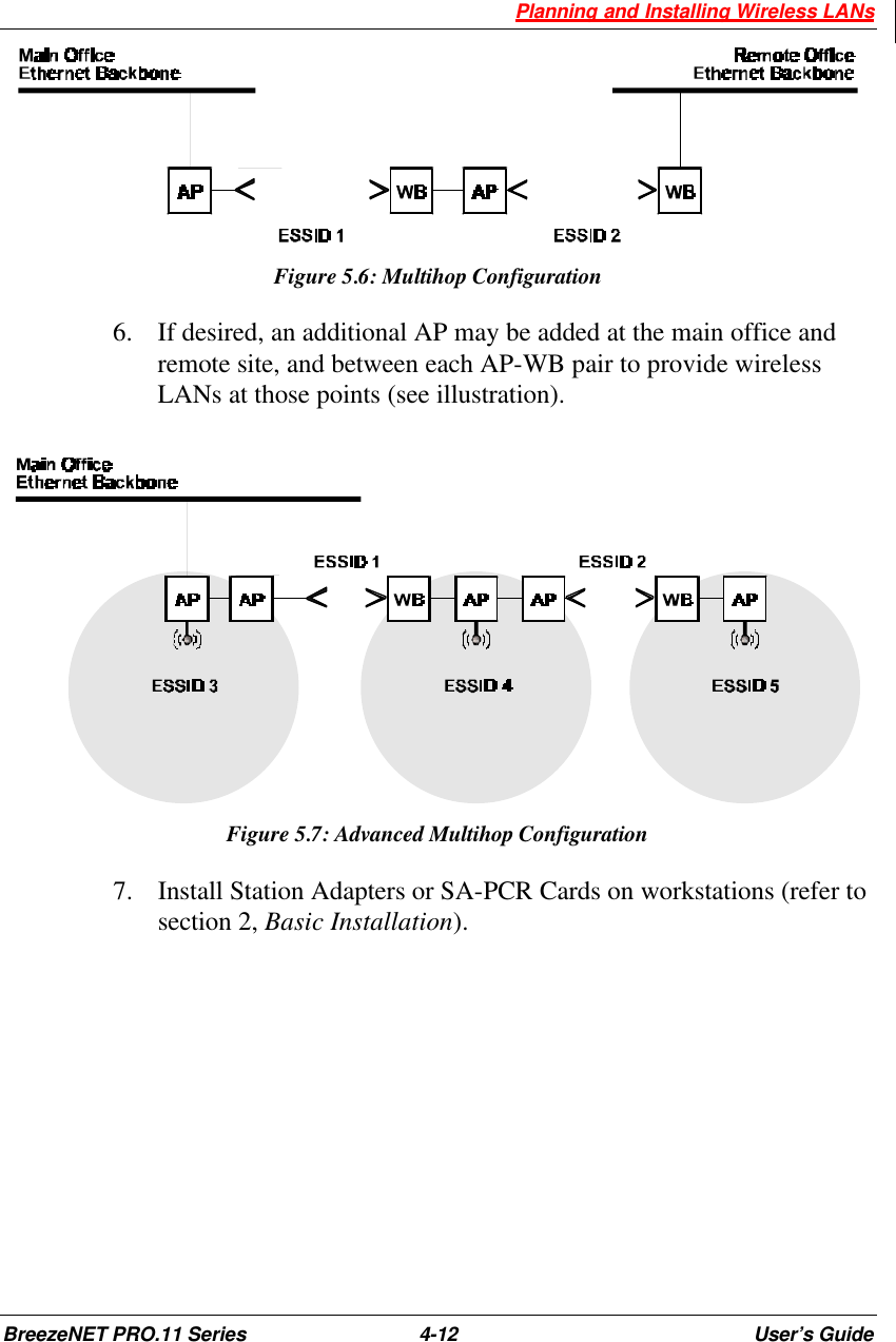
Manual
Navigation menu
Upload a User Manual
Namespaces
Wiki Guide
HTML
PDF
Info
Views
User Manual
Discussion / Help
Navigation


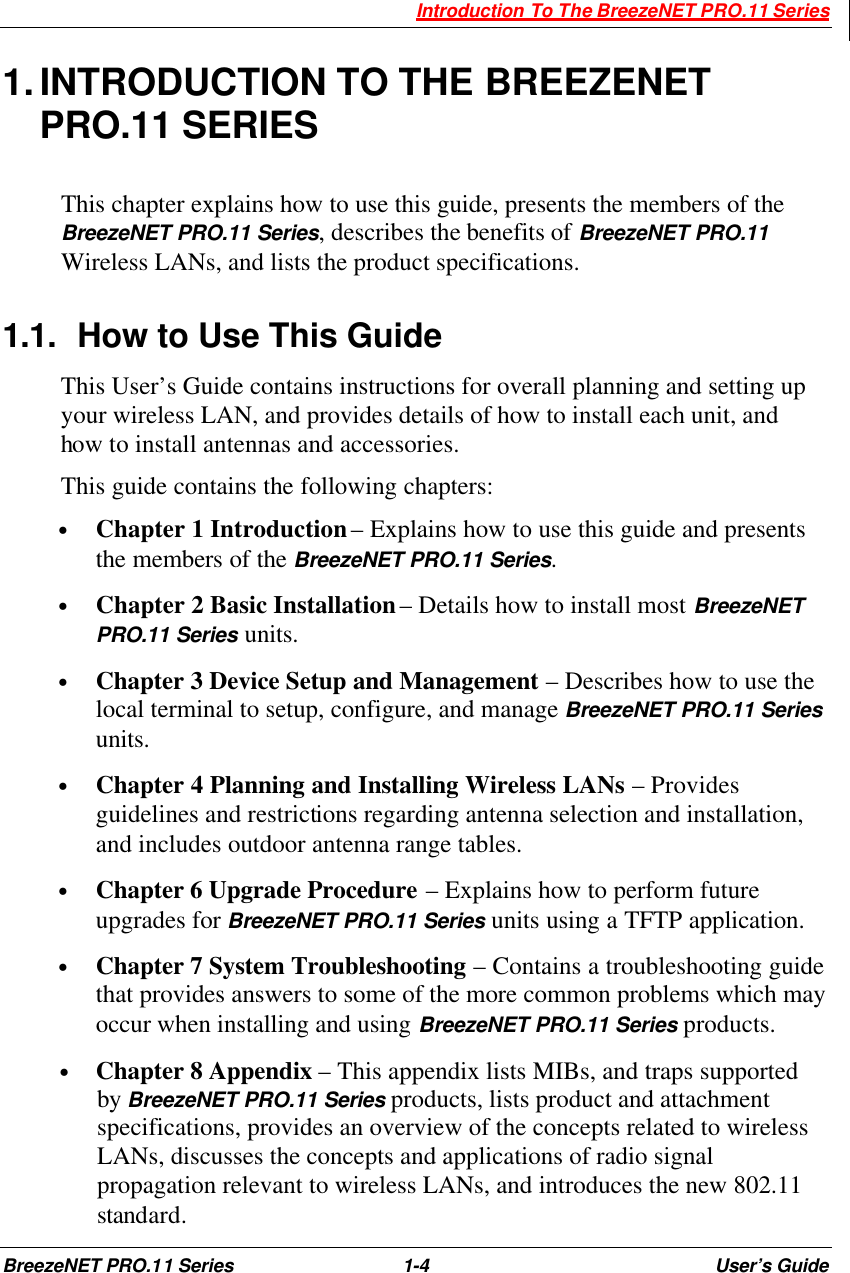
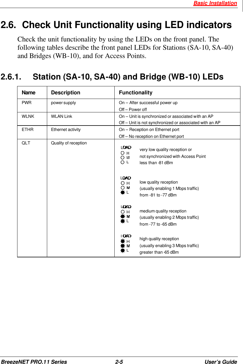
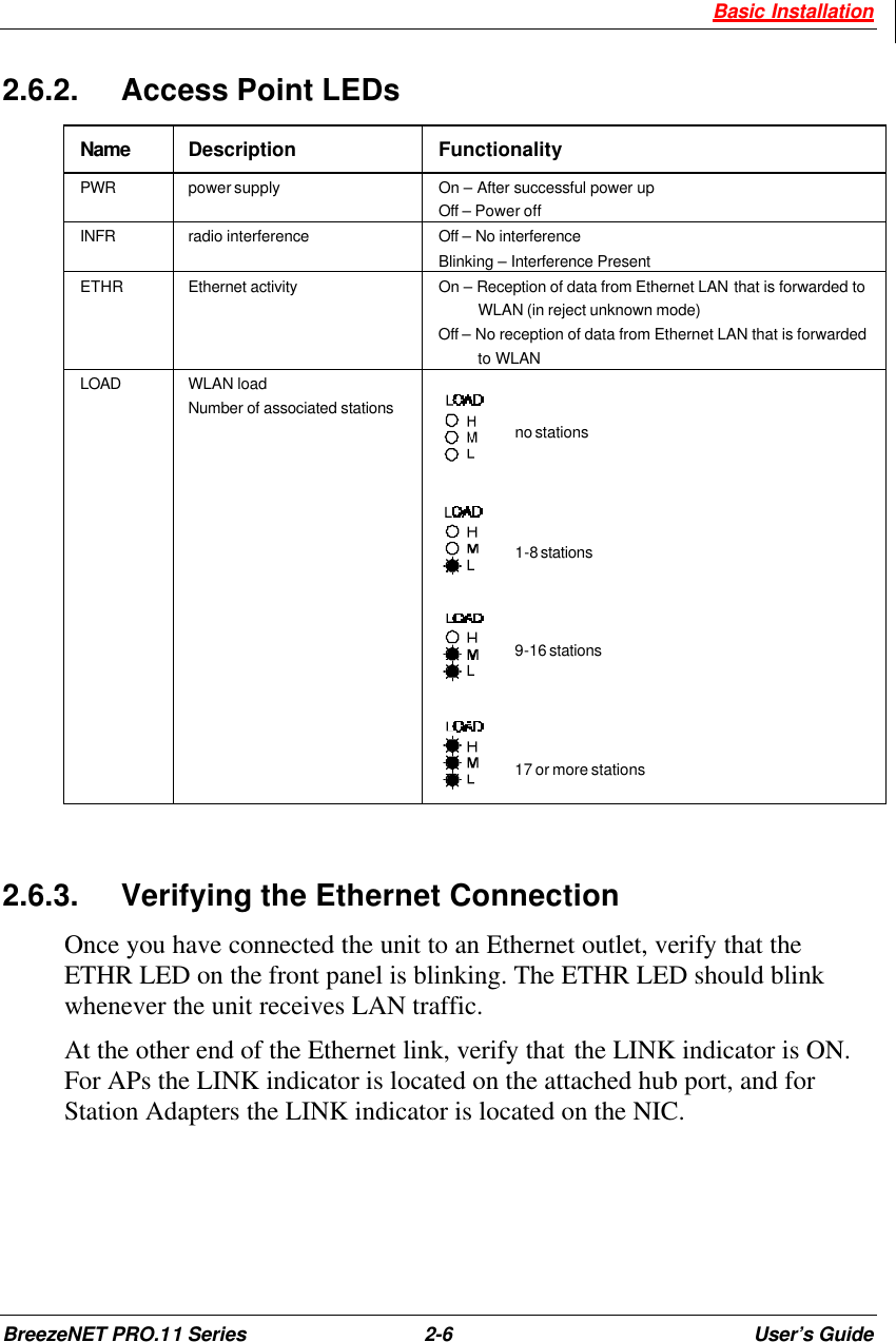
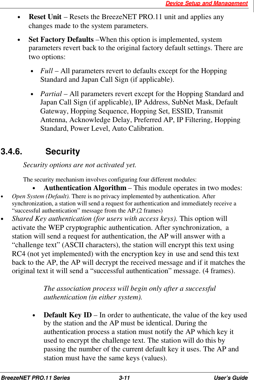
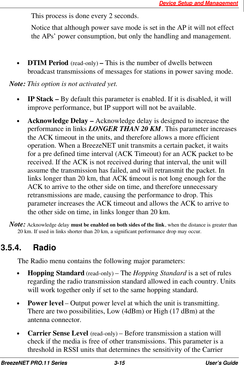
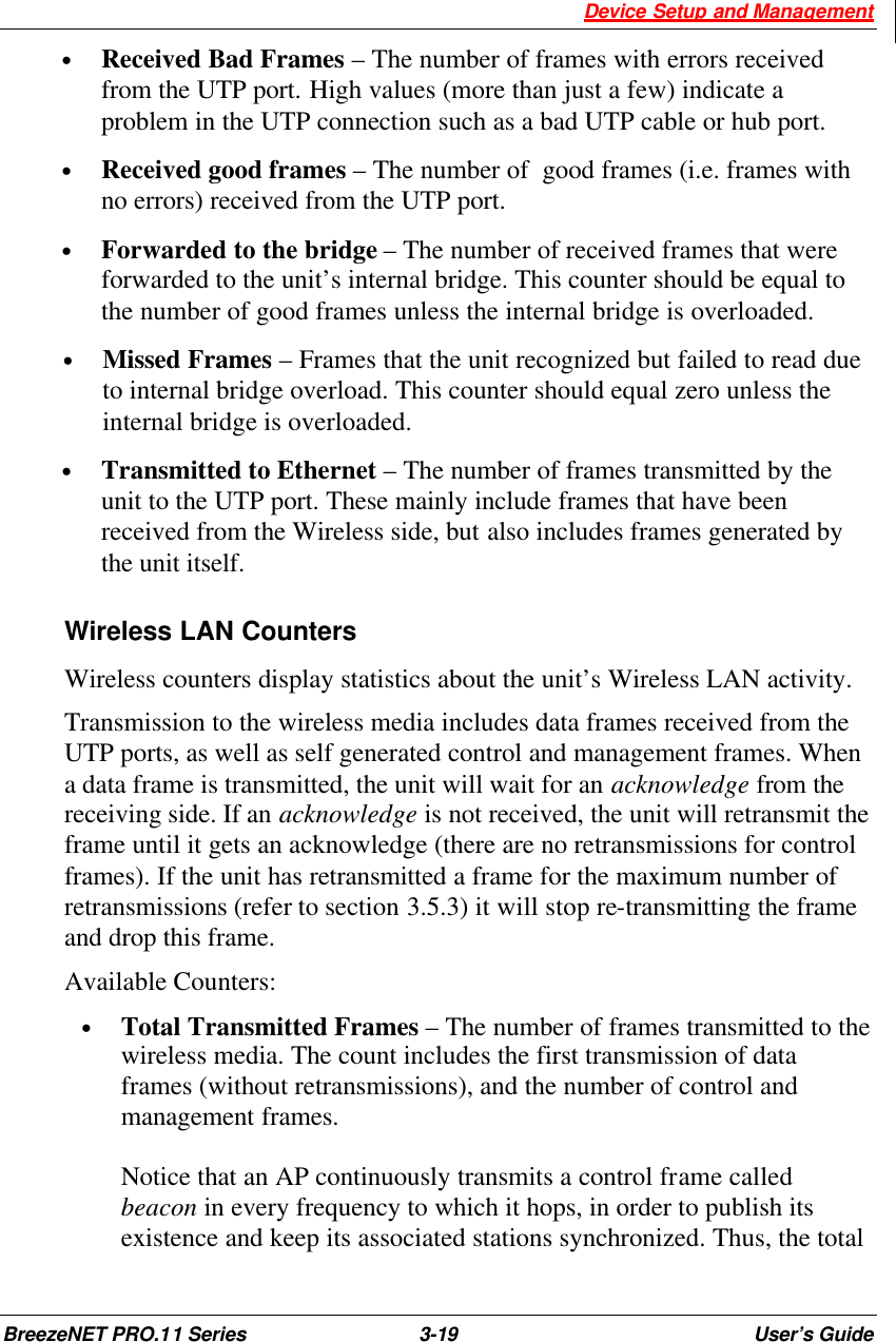
![Device Setup and Management BreezeNET PRO.11 Series 3-25 User’s Guide Version : 4.3.10 Date: 15 Feb 1999 23:49:56 #Pack Ant RSSI1 RSSI2 Bit_Err Freq Rate Quality 58 1 108 91 0 19 3 ########### 59 2 110 112 0 42 3 ########### 60 2 86 88 0 14 3 ########... 61 2 109 112 0 46 3 ########### 62 1 109 107 0 24 3 ########### 63 1 108 106 0 22 3 ########### 64 1 112 108 0 33 3 ########### 65 1 111 107 0 25 3 ########### 66 1 111 111 0 41 3 ########### 67 2 111 110 0 79 3 ########### 68 1 115 111 0 64 3 ########### 69 1 115 111 0 65 3 ########### 70 2 111 111 0 56 3 ########### 71 2 110 111 0 55 3 ########### Figure 3.6: Receive Statistics 7. The RSSI is given in arbitrary units. Use the following graph (Figure 3.7) to correlate RSSI to dBm. RSSI Vs. dBm5060708090100110120130-30 -40 -45 -50 -55 -60 -65 -70 -75 -78 -81 -83 -85RF Level [dbm]RSSI Value Figure 3.7: RSSI to dBm Graph 8. Re-align the antennas until the maximum received signal strength is obtained. As you align the antennas, you will see that the RSSI (received signal strength indicator) continually increases until it reaches a certain level after which the RSSI begins to decrease. This is the maximum attainable RSSI level indicating optimum receive antenna alignment.](https://usermanual.wiki/Alvarion-Technologies/EAP-11AMP.Manual/User-Guide-119910-Page-47.png)