Alvarion Technologies ERB-DS11 BreezeNET BU-DS.11 & RB-DS.11 User Manual
Alvarion Ltd. BreezeNET BU-DS.11 & RB-DS.11
UserManual.wiki
>
Alvarion Technologies
>
ERB-DS11 User Manual
>
73 pages
Contents
1.
73 pages
2.
revised user manual
73 pages
Navigation menu
Upload a User Manual
Namespaces
Wiki Guide
HTML
PDF
Info
Views
User Manual
Discussion / Help
Navigation
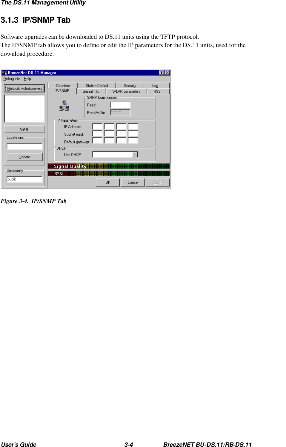
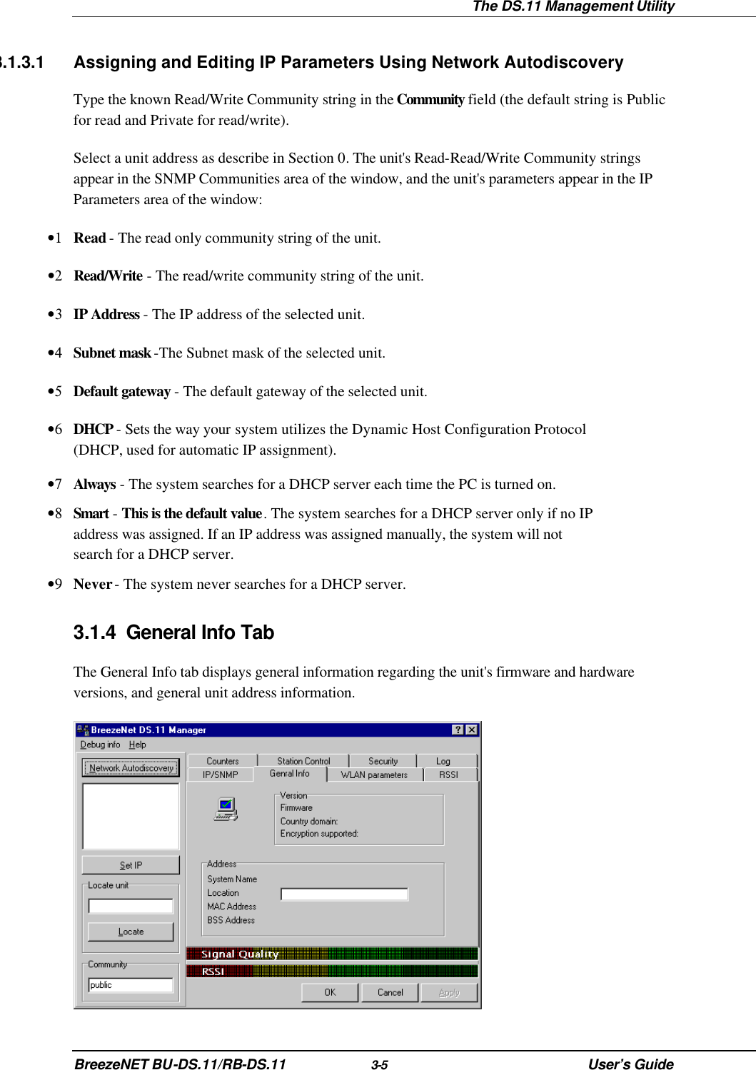
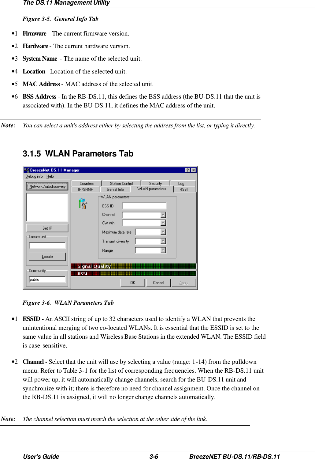
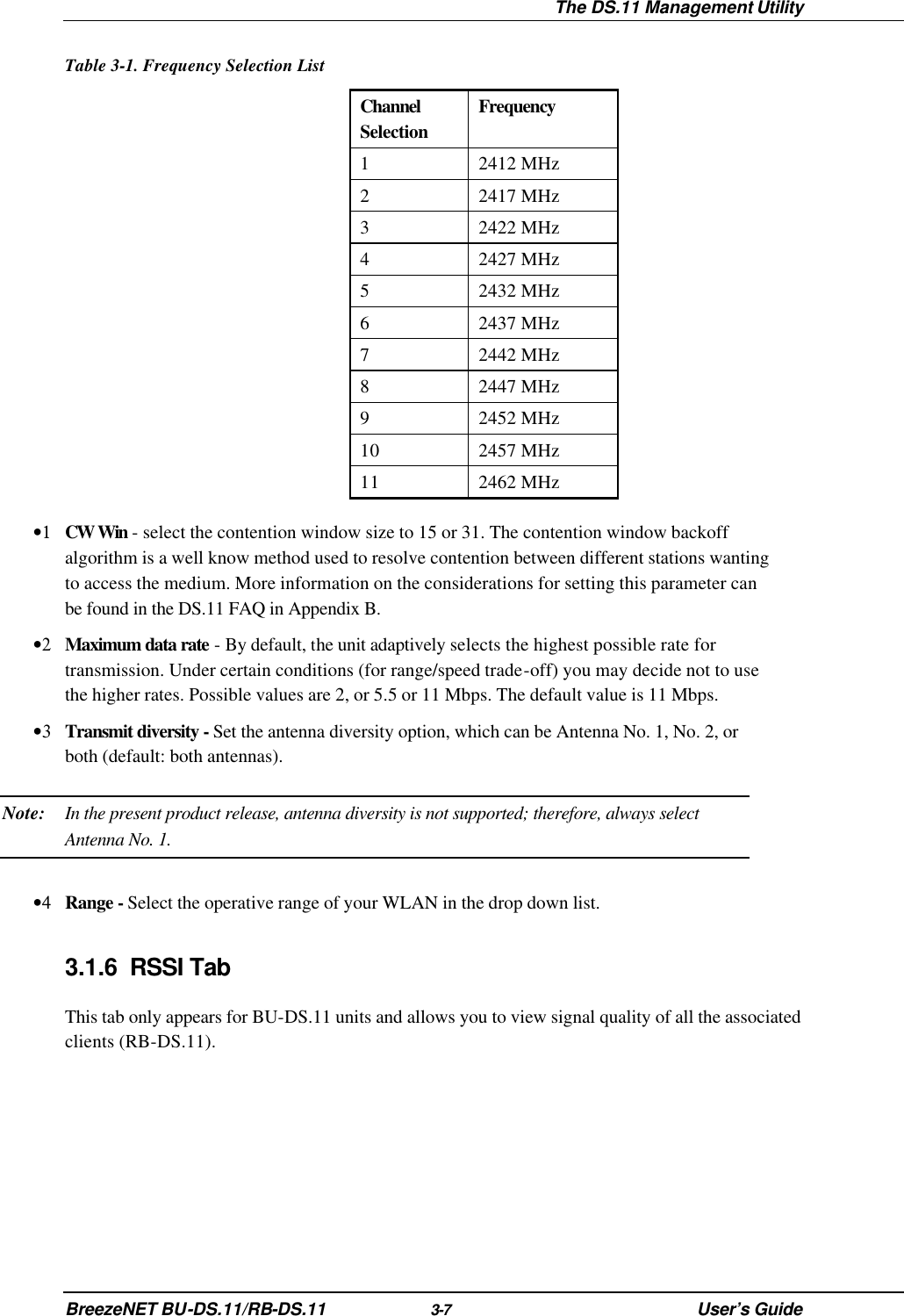
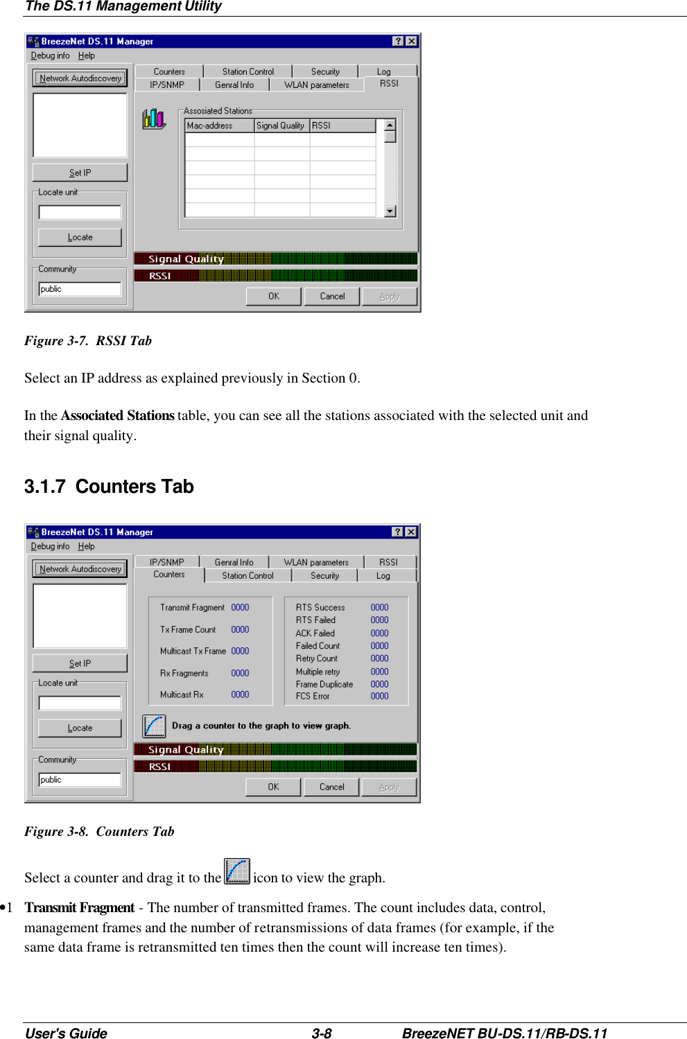
![Software DownLoad Procedure BreezeNET BU-DS.11/RB-DS.11 5-1 User’s Guide 5. SOFTWARE DOWNLOAD PROCEDURE 1. Set the unit's IP address, using the DS.11 Management utility, and verify that the PC's IP address belongs to the same Subnet Mask as the unit. 2. Ping the unit's IP address. Make sure that the Ping replies are being received. 3. Use the TFTP utility on the PC: i) Syntax: TFTP [-i] destination host [PUT] source file [password] ii) Example: TFTP -i 199.203.141.30 put ap1100.arm private Download will be completed within two minutes, and a message of successful file transfer will be shown on the screen. 4. The unit resets itself automatically. 5. Check the diagnostics LEDs to verify that there is not hardware failure, and use the DS.11 Management utility to make sure that the version number is correct. Note: Do not disconnect any cables or try to stop the process before downloading is completed. All configured parameters are kept during the upgrade/download procedure.](https://usermanual.wiki/Alvarion-Technologies/ERB-DS11.73-pages/User-Guide-107544-Page-49.png)