Alvarion Technologies EXTR-36 Base station transceiver User Manual BreezeMAX Extreme Ver 1 5 System Manual
Alvarion Technologies Ltd. Base station transceiver BreezeMAX Extreme Ver 1 5 System Manual
Contents
- 1. User manual
- 2. Rev2 of the Users manual
- 3. user manual
Rev2 of the Users manual

BreezeMAX® Extreme
System Manual
Software Version 1.5
May 2010
P/N 215655

Document History
BreezeMAX Extreme ii System Manual
Document History
Topic Description Date Issued
Preliminary Release for Early Field
Trials
New System Manual March 2009
Preliminary Release for Beta New System Manual June 2009
First Release for GA New System Manual June 2009
3.65 GHz band A new radio band August 2009
MAC Access Lists New features in ASN-GW menu September 2009
Service Profiles Added a new Service Type - PPPoE September 2009
Multiple Service Flows Added support for Ethernet CS services.
New Classifier types (VLAN ID, VLAN
Priority)
September 2009
Service Interface Added support for Ethernet CS services.
New parameters (VLAN Transparency, VLAN
Priority Marking, VLAN List)
September 2009
Sector DFS Parameters Updated-added Radar Detection Threshold
parameter.
September 2009
Integral 5 GHz Antenna Updated specifications of 5 GHz Integral
antenna (Table 1-9)
October 2009
External 5 GHz Antennas Added 8 dBi OMNI (Table 1-10) October 2009
4.9 GHz FCC Band Added a note on Tx Power limitations:
Sections 1.4.13, 4.7.2.2.1.6
October 2009
Radio Standard Added FCC Part 90 Subpart Y, FCC Part 15
Subpart B (Table 1-17)
October 2009
Available Radio Bands Removed 3.5 GHz units October 2009
Timeout after 3 unsuccessful login
attempts
Updated to 10 minutes (Section 4.2.1) October 2009
Load to Shadow operation Updated description-not allowed if the unit is
running from Shadow (Section 4.5.5.4.3)
October 2009
Forwarding Rules - Relay Mode Updated description (Section 4.6.2.11.3) October 2009
Service Interface - VLAN Interface
parameter
Updated description (Section 4.6.2.10.5) October 2009
Service Rule Classifiers No classifiers should be defined for PPPoE
services (Sections 4.6.2.7, 4.6.2.8)
October 2009
Band Names for Australia Updated parameters (Tables 4-3, 4-4,
4-19, 4-21)
October 2009

Document History
BreezeMAX Extreme iii System Manual
System Configurations
Section 1.3.4
Updated, new configurations. February 2010
Data Communication (Ethernet
Port) specifications
Section 1.4.9
Corrected Standards Compliance (IEEE
8033u corrected to IEEE 802u).
Maximum Packet Size corrected to Maximum
Frame Size
February 2010
BTS Menu, Show Summary
Section 4.5.1
Updated February 2010
BTS Menu, Show Properties
Section 4.5.2
Updated February 2010
BTS Menu, Show License
Properties
Section 4.5.3
New feature February 2010
Operation Modes
Section 4.5.4.5.5
Updated (new options, added details) February 2010
DL/UL Ratio
Section 4.5.4.5.6
Updated description February 2010
DFS/DCS
Section 4.5.4.5.8
Updated, added DCS feature and new
Random Channel Selection parameter.
February 2010
Unit Contro
Section 4.5.5
Added new feature-License Files Control February 2010
License Files Control
Section 4.5.5.6
New feature February 2010
BTS Performance Counters
Section 4.5.7
Corrected (added BTS IP Address in Ethernet
counters, corrected order of counters)
February 2010
Service Profile Type
Section 4.6.2.4.3
Updated (new types) February 2010
HARQ Repetitions
Section 4.6.2.4.4
Updated (new service profile types) February 2010
QoS Profiles
Section 4.6.2.5
Updated to reflect support of ERT. February 2010
Service Groups
Section 4.6.2.9
Support of new DHCP modes and relevant
parameters.
New Service Group Gateway and Service
Group VLAN ID parameters
Updated description of Attribute 31 and
Attribute 32.
February 2010
Topic Description Date Issued

Document History
BreezeMAX Extreme iv System Manual
MAC Access Lists
Section 4.6.3
Updated to reflect new features (Allow/Deny
feature, single addresses/ranges lists, Default
Access parameter).
February 2010
Sector Menu
Section 4.7
Support of configurations with 2 sectors and 2
BSs.
New features-DCS, Spectrum Analyzer..
Updated functionality of Usable Frequencies
Updated description of Bandwidth,
Frequency, Tx Power.
Updated description of DFS feature.
February 2010
BS Menu
Section 4.8
Support of configurations with 2 BSs.
Updated description of BS Bandwidth, Cell
Radius, Diversity, Major Groups
Updated range for Map Repetition.
Removed: Perform and Show UL Thermal
Noise Measurement.
Added support of ERT in R6 Interface
parameters (DSCP QoS Marking, VLAN
Priority QoS Marking).
February 2010
Radio Channel Menu
Section 4.9
Support of configurations with 2 BSs.
Updated description of Radio Channel
Frequency.
February 2010
Configuration and Management
Section 1.4.10
Added Security February 2010
3.65 GHz BTS
Section 1.4.2
Added support of 7 MHz February 2010
GPS Menu
Section 4.11
Chaining is supported February 2010
Select By MAC
Section 4.12.5
Removed: Perform and Show MS Frequency
Shift Measurement
February 2010
Network Architectures
Section 1.3.3
New February 2010
Power Supply
Section 1.3.5
Updated February 2010
GPS Antenna
Section 1.3.7
Updated February 2010
Topic Description Date Issued

Document History
BreezeMAX Extreme v System Manual
External 5 GHz Antennas
Appendix 1.4.6.2
New antenna (BS 4.9-5.9GHz Dual Slant 90°
16dBi), removed ANT, BS, 5.15-5.875G,
V8dBi, OMNI, updated names of
ANT,BS,4.9-5.875G,90V, 16.5dBi,FLAT and
ANT,BS,4.9-5.1G,120V, 15dBi, FLAT
February 2010
Introduction to Services Menu
Section 4.6.2.1
New section February 2010
Working Mode names Updated Working Mode names February 2010
Sensitivity
Section 1.4.4
Added table for 3.65 GHz band. Changed
table for 5 GHz band to two tables (4.9 GHz
band and 5.4 GHz band) with updated values.
February 2010
DFS
Section 4.7.2.2.2.1
DFS parameters are not configurable February 2010
Service Groups
Section 4.6.2.9
Updated-new/removed/modified parameters February 2010
Band Name
Table 4-2, Table 4-3
Updated Band Names and dependent
parameters
February 2010
Default Service Components
Section 4.6.2.12
New February 2010
Parameters Summary
Section 4.13
Updated to reflect version 1.5 changes. February 2010
Topic Description Date Issued

Legal Rights
BreezeMAX Extreme vi System Manual
Le gal Rights
© Copyright 2010 Alvarion Ltd. All rights reserved.
The material contained herein is proprietary, privileged, and confidential and
owned by Alvarion or its third party licensors. No disclosure thereof shall be made
to third parties without the express written permission of Alvarion Ltd.
Alvarion Ltd. reserves the right to alter the equipment specifications and
descriptions in this publication without prior notice. No part of this publication
shall be deemed to be part of any contract or warranty unless specifically
incorporated by reference into such contract or warranty.
Trade Names
Alvarion®, BreezeCOM®, WALKair®, WALKnet®, BreezeNET®, BreezeACCESS®,
BreezeLINK®, BreezeMAX®, BreezeLITE®, BreezePHONE®, 4Motion®, and/or other
products and/or services referenced here in are either registered trademarks,
trademarks or service marks of Alvarion Ltd.
All other names are or may be the trademarks of their respective owners.
“WiMAX Forum” is a registered trademark of the WiMAX Forum. “WiMAX”, the
WiMAX Forum logo, “WiMAX Forum Certified”, and the WiMAX Forum Certified
logo are trademarks of the WiMAX Forum.
Statem ent of Conditions
The information contained in this manual is subject to change without notice.
Alvarion Ltd. shall not be liable for errors contained herein or for incidental or
consequential damages in connection with the furnishing, performance, or use of
this manual or equipment supplied with it.
Wa rra nt ies a nd Discla im e rs
All Alvarion Ltd. (“Alvarion”) products purchased from Alvarion or through any of
Alvarion's authorized resellers are subject to the following warranty and product
liability terms and conditions.
Exclusive Wa rranty
(a) Alvarion warrants that the Product hardware it supplies and the tangible
media on which any software is installed, under normal use and conditions, will
be free from significant defects in materials and workmanship for a period of
fourteen (14) months from the date of shipment of a given Product to Purchaser
(the “Warranty Period”). Alvarion will, at its sole option and as Purchaser's sole
remedy, repair or replace any defective Product in accordance with Alvarion'
standard R&R procedure.

Legal Rights
BreezeMAX Extreme vii System Manual
(b) With respect to the Firmware, Alvarion warrants the correct functionality
according to the attached documentation, for a period of fourteen (14) month from
invoice date (the “Warranty Period”). During the Warranty Period, Alvarion may
release to its Customers firmware updates, which include additional performance
improvements and/or bug fixes, upon availability (the “Warranty”). Bug fixes,
temporary patches and/or workarounds may be supplied as Firmware updates.
Additional hardware, if required, to install or use Firmware updates must be
purchased by the Customer. Alvarion will be obligated to support solely the two (2)
most recent Software major releases.
ALVARION SHALL NOT BE LIABLE UNDER THIS WARRANTY IF ITS TESTING
AND EXAMINATION DISCLOSE THAT THE ALLEGED DEFECT IN THE PRODUCT
DOES NOT EXIST OR WAS CAUSED BY PURCHASER'S OR ANY THIRD
PERSON'S MISUSE, NEGLIGENCE, IMPROPER INSTALLATION OR IMPROPER
TESTING, UNAUTHORIZED ATTEMPTS TO REPAIR, OR ANY OTHER CAUSE
BEYOND THE RANGE OF THE INTENDED USE, OR BY ACCIDENT, FIRE,
LIGHTNING OR OTHER HAZARD.
Disclaime r
(a) The Software is sold on an “AS IS” basis. Alvarion, its affiliates or its licensors
MAKE NO WARRANTIES, WHATSOEVER, WHETHER EXPRESS OR IMPLIED,
WITH RESPECT TO THE SOFTWARE AND THE ACCOMPANYING
DOCUMENTATION. ALVARION SPECIFICALLY DISCLAIMS ALL IMPLIED
WARRANTIES OF MERCHANTABILITY AND FITNESS FOR A PARTICULAR
PURPOSE AND NON-INFRINGEMENT WITH RESPECT TO THE SOFTWARE.
UNITS OF PRODUCT (INCLUDING ALL THE SOFTWARE) DELIVERED TO
PURCHASER HEREUNDER ARE NOT FAULT-TOLERANT AND ARE NOT
DESIGNED, MANUFACTURED OR INTENDED FOR USE OR RESALE IN
APPLICATIONS WHERE THE FAILURE, MALFUNCTION OR INACCURACY OF
PRODUCTS CARRIES A RISK OF DEATH OR BODILY INJURY OR SEVERE
PHYSICAL OR ENVIRONMENTAL DAMAGE (“HIGH RISK ACTIVITIES”). HIGH
RISK ACTIVITIES MAY INCLUDE, BUT ARE NOT LIMITED TO, USE AS PART OF
ON-LINE CONTROL SYSTEMS IN HAZARDOUS ENVIRONMENTS REQUIRING
FAIL-SAFE PERFORMANCE, SUCH AS IN THE OPERATION OF NUCLEAR
FACILITIES, AIRCRAFT NAVIGATION OR COMMUNICATION SYSTEMS, AIR
TRAFFIC CONTROL, LIFE SUPPORT MACHINES, WEAPONS SYSTEMS OR
OTHER APPLICATIONS REPRESENTING A SIMILAR DEGREE OF POTENTIAL
HAZARD. ALVARION SPECIFICALLY DISCLAIMS ANY EXPRESS OR IMPLIED
WARRANTY OF FITNESS FOR HIGH RISK ACTIVITIES.
(b) PURCHASER'S SOLE REMEDY FOR BREACH OF THE EXPRESS
WARRANTIES ABOVE SHALL BE REPLACEMENT OR REFUND OF THE
PURCHASE PRICE AS SPECIFIED ABOVE, AT ALVARION'S OPTION. TO THE

Legal Rights
BreezeMAX Extreme viii System Manual
FULLEST EXTENT ALLOWED BY LAW, THE WARRANTIES AND REMEDIES SET
FORTH IN THIS AGREEMENT ARE EXCLUSIVE AND IN LIEU OF ALL OTHER
WARRANTIES OR CONDITIONS, EXPRESS OR IMPLIED, EITHER IN FACT OR BY
OPERATION OF LAW, STATUTORY OR OTHERWISE, INCLUDING BUT NOT
LIMITED TO WARRANTIES, TERMS OR CONDITIONS OF MERCHANTABILITY,
FITNESS FOR A PARTICULAR PURPOSE, SATISFACTORY QUALITY,
CORRESPONDENCE WITH DESCRIPTION, NON-INFRINGEMENT, AND
ACCURACY OF INFORMATION GENERATED. ALL OF WHICH ARE EXPRESSLY
DISCLAIMED. ALVARION' WARRANTIES HEREIN RUN ONLY TO PURCHASER,
AND ARE NOT EXTENDED TO ANY THIRD PARTIES. ALVARION NEITHER
ASSUMES NOR AUTHORIZES ANY OTHER PERSON TO ASSUME FOR IT ANY
OTHER LIABILITY IN CONNECTION WITH THE SALE, INSTALLATION,
MAINTENANCE OR USE OF ITS PRODUCTS.
Limitation of Lia bility
(a) ALVARION SHALL NOT BE LIABLE TO THE PURCHASER OR TO ANY THIRD
PARTY, FOR ANY LOSS OF PROFITS, LOSS OF USE, INTERRUPTION OF
BUSINESS OR FOR ANY INDIRECT, SPECIAL, INCIDENTAL, PUNITIVE OR
CONSEQUENTIAL DAMAGES OF ANY KIND, WHETHER ARISING UNDER
BREACH OF CONTRACT, TORT (INCLUDING NEGLIGENCE), STRICT LIABILITY
OR OTHERWISE AND WHETHER BASED ON THIS AGREEMENT OR
OTHERWISE, EVEN IF ADVISED OF THE POSSIBILITY OF SUCH DAMAGES.
(b) TO THE EXTENT PERMITTED BY APPLICABLE LAW, IN NO EVENT SHALL
THE LIABILITY FOR DAMAGES HEREUNDER OF ALVARION OR ITS EMPLOYEES
OR AGENTS EXCEED THE PURCHASE PRICE PAID FOR THE PRODUCT BY
PURCHASER, NOR SHALL THE AGGREGATE LIABILITY FOR DAMAGES TO ALL
PARTIES REGARDING ANY PRODUCT EXCEED THE PURCHASE PRICE PAID
FOR THAT PRODUCT BY THAT PARTY (EXCEPT IN THE CASE OF A BREACH OF
A PARTY'S CONFIDENTIALITY OBLIGATIONS).
Ra dio Frequency I nt erfe rence St atem ent
The Base Transceiver Station (BTS) equipment has been tested and found to
comply with the limits for a class A digital device, pursuant to ETSI EN 301 489-1
rules and Part 15 of the FCC Rules. These limits are designed to provide
reasonable protection against harmful interference when the equipment is
operated in commercial, business and industrial environments. This equipment
generates, uses, and can radiate radio frequency energy and, if not installed and
used in accordance with the instruction manual, may cause harmful interference
to radio communications. Operation of this equipment in a residential area is
likely to cause harmful interference in which case the user will be required to
correct the interference at the user's own expense.

Legal Rights
BreezeMAX Extreme ix System Manual
FCC Ra diat ion Ha zard Wa rning
To comply with FCC RF exposure requirements in Section 1.1307 and 2.1091 of
FCC Rules, the antenna used for this transmitter must be fixed-mounted on
outdoor permanent structures with a separation distance of at least 2 meters from
all persons.
Ca nadia n Ra dio Sta ndards Spec ificat ions (RSS) Compliance State me nt
This device has been designed to operate with the antennas listed in Section 1.4.6
of this manual (“5 GHz Antennas” on page 25), and having a maximum gain of 17
dBi. Antennas not included in this list or having a gain greater than 17 dBi are
strictly prohibited for use with this device. The required antenna impedance is 50
ohms.
To reduce potential radio interference to other users, the antenna type and its
gain should be so chosen that the equivalent isotropically radiated power (e.i.r.p.)
is not more than that permitted for successful communication.
R& T TE Com pliance St atem ent
This equipment complies with the appropriate essential requirements of Article 3
of the R&TTE Directive 1999/5/EC.
Sa fe t y Considerat ions - Ge neral
For the following safety considerations, “Instrument” means the BreezeMAX units'
components and their cables.
Grounding
BTS chassis, Power Feeders and Outdoor Units are required to be bonded to
protective grounding using the bonding stud or screw provided with each unit.
Sa fe t y Considerat ions - DC Pow ered Equipm ent
Restricted Access Area: The DC powered equipment should only be installed in a
Restricted Access Area.
Installation Codes: The equipment must be installed according to the latest
edition of the country national electrical codes. For North America, equipment
must be installed in accordance with the US National Electrical Code and the
Canadian Electrical Code.
CAUTION ATTENTION
Risk of electric shock and energy hazard. Risque de décharge électrique et
d'electrocution.

Legal Rights
BreezeMAX Extreme x System Manual
Overcurrent Protection: A readily accessible Listed branch circuit overcurrent
protective device, rated 60A for the BTS or 20A for the Power Feeder, must be
incorporated in the building wiring.
CAUTION: This equipment is designed to permit connection between the earthed
conductor of the DC supply circuit and the grounding conductor at the
equipment. See installation instructions.
The equipment must be connected directly to the DC Supply System
grounding electrode conductor.
All equipment in the immediate vicinity must be grounded in the same way,
and not be grounded elsewhere.
The DC supply system is to be local, i.e. within the same premises as the
equipment.
There shall be no disconnect device between the grounded circuit conductor of
the DC source (return) and the point of connection of the grounding electrode
conductor.
Ca ut ion
To avoid electrical shock, do not perform any servicing unless you are qualified to
do so.
Line Volta ge
Before connecting this instrument to the power line, make sure that the voltage of
the power source matches the requirements of the instrument.
Ra dio
The instrument transmits radio energy during normal operation. To avoid possible
harmful exposure to this energy, do not stand or work for extended periods of time
in front of its antenna. The long-term characteristics or the possible physiological
effects of radio frequency electromagnetic fields have not been yet fully
investigated.
Outdoor U nits a nd Ant enna s I nsta llat ion a nd Grounding
Ensure that outdoor units, antennas and supporting structures are properly
installed to eliminate any physical hazard to either people or property. Make sure
that the installation of the outdoor unit, antenna and cables is performed in
accordance with all relevant national and local building and safety codes. Even
where grounding is not mandatory according to applicable regulation and national

Legal Rights
BreezeMAX Extreme xi System Manual
codes, it is highly recommended to ensure that the outdoor unit and the antenna
mast (when using external antenna) are grounded and suitable lightning
protection devices are used so as to provide protection against voltage surges and
static charges. In any event, Alvarion is not liable for any injury, damage or
regulation violations associated with or caused by installation, grounding or
lightning protection.
Disposal of Ele ctronic a nd Elec tric a l Wast e
Disposal of Electronic and Electrical Waste
Pursuant to the WEEE EU Directive electronic and electrical waste must not be disposed of with
unsorted waste. Please contact your local recycling authority for disposal of this product.

Important Notice
BreezeMAX Extreme xii System Manual
Important N ot ic e
This user manual is delivered subject to the following conditions and restrictions:
This manual contains proprietary information belonging to Alvarion Ltd. Such
information is supplied solely for the purpose of assisting properly authorized
users of the respective Alvarion products.
No part of its contents may be used for any other purpose, disclosed to any
person or firm or reproduced by any means, electronic and mechanical,
without the express prior written permission of Alvarion Ltd.
The text and graphics are for the purpose of illustration and reference only.
The specifications on which they are based are subject to change without
notice.
The software described in this document is furnished under a license. The
software may be used or copied only in accordance with the terms of that
license.
Information in this document is subject to change without notice. Corporate
and individual names and data used in examples herein are fictitious unless
otherwise noted.
Alvarion Ltd. reserves the right to alter the equipment specifications and
descriptions in this publication without prior notice. No part of this
publication shall be deemed to be part of any contract or warranty unless
specifically incorporated by reference into such contract or warranty.
The information contained herein is merely descriptive in nature, and does not
constitute an offer for the sale of the product described herein.
Any changes or modifications of equipment, including opening of the
equipment not expressly approved by Alvarion Ltd. will void equipment
warranty and any repair thereafter shall be charged for. It could also void the
user's authority to operate the equipment.
Some of the equipment provided by Alvarion and specified in this manual, is
manufactured and warranted by third parties. All such equipment must be
installed and handled in full compliance with the instructions provided by such
manufacturers as attached to this manual or provided thereafter by Alvarion or
the manufacturers. Non-compliance with such instructions may result in serious

Important Notice
BreezeMAX Extreme xiii System Manual
damage and/or bodily harm and/or void the user's authority to operate the
equipment and/or revoke the warranty provided by such manufacturer.

About This Manual
BreezeMAX Extreme xiv System Manual
About T his Manual
This manual describes the BreezeMAX Extreme solution, and details how to
install, operate and manage the BTS system components.
This manual is intended for technicians responsible for installing, setting and
operating the BreezeMAX Extreme BTS equipment, and for system administrators
responsible for managing the system.
This manual contains the following chapters and appendices:
Chapter 1 - System description: Describes the BreezeMAX Extreme BTS and
its components.
Chapter 2 - Installation: Describes how to install the BTS components.
Chapter 3 - Commissioning: Describes how to configure basic parameters
and validate units' operation.
Chapter 4 - Operation and Administration Using the CLI: Describes how to
use the Command Line Interface (CLI) for configuring parameters, checking
system status and monitoring performance.
Glossary: A listing of commonly used terms.

Contents
BreezeMAX Extreme xv System Manual
Contents
Chapte r 1 - Syst em De sc ript ion
1.1 About WiMAX................................................................................................................3
1.2 WiMAX Network Architecture......................................................................................4
1.2.1 The WiMAX Network Reference Model ..............................................................4
1.2.2 Access Service Network (ASN)...........................................................................5
1.2.3 Connectivity Service Network (CSN) ..................................................................6
1.2.4 Network Access Provider (NAP) .........................................................................6
1.2.5 Network Service Provider (NSP).........................................................................6
1.2.6 Base Station (BS)................................................................................................7
1.2.7 ASN Gateway (ASN-GW) ...................................................................................7
1.2.8 Reference Points.................................................................................................9
1.3 BreezeMAX Extreme ..................................................................................................11
1.3.1 General .............................................................................................................11
1.3.2 System Components.........................................................................................12
1.3.3 Network Architectures .......................................................................................12
1.3.4 System Configurations ......................................................................................14
1.3.5 Power Supply ....................................................................................................18
1.3.6 Radio Antennas.................................................................................................19
1.3.7 GPS Antenna ....................................................................................................19
1.4 Specifications .............................................................................................................20
1.4.1 General Modem & Radio...................................................................................20
1.4.2 3.65 GHz BTS ...................................................................................................20
1.4.3 5 GHz BTS ........................................................................................................21

Contents
BreezeMAX Extreme xvi System Manual
1.4.4 Sensitivity ..........................................................................................................22
1.4.5 3.65 GHz Antennas...........................................................................................24
1.4.6 5 GHz Antennas................................................................................................25
1.4.7 Power Supply ....................................................................................................26
1.4.8 GPS Antennas ..................................................................................................27
1.4.9 Data Communication (Ethernet Port) ................................................................27
1.4.10 Configuration and Management........................................................................28
1.4.11 Environmental ...................................................................................................28
1.4.12 BTS Standards Compliance, General ...............................................................28
1.4.13 Notes on Maximum Tx Power Limitations for 5 GHz Units: ..............................29
Chapte r 2 - I nsta lla tion
2.1 Site Deployment Options...........................................................................................33
2.1.1 BTS Installation Options....................................................................................33
2.1.2 Antenna Options ...............................................................................................33
2.1.3 GPS Options .....................................................................................................33
2.1.4 Power Feeding Options.....................................................................................34
2.2 BTS Installation ..........................................................................................................37
2.2.1 Installation Requirements..................................................................................37
2.2.2 Assembling the Tilt Bracket on the BTS............................................................39
2.2.3 Installing a Lightning Arrestor............................................................................41
2.2.4 Installing the BTS on a Pole..............................................................................42
2.2.5 Mounting the BTS on the Carriage....................................................................45
2.2.6 Wall Mount Installation ......................................................................................47
2.3 GPS Installation..........................................................................................................49
2.3.1 Installation Requirements..................................................................................49
2.3.2 Packing List.......................................................................................................49

Contents
BreezeMAX Extreme xvii System Manual
2.3.3 Installing the GPS .............................................................................................50
2.4 Indoor Power Supply Installation .............................................................................54
2.4.1 PoE AC/DC Power Supply ................................................................................54
2.4.2 High Power AC/DC Power Supply Unit.............................................................56
2.5 Cable Connections.....................................................................................................57
2.5.1 Cable Connection..............................................................................................59
2.6 External Antennas Connection .................................................................................64
Chapte r 3 - Comm issioning
3.1 Configuring Parameters Required for Remote Management.................................67
3.2 Operation Verification................................................................................................69
Chapte r 4 - Operat ion and Administrat ion
4.1 BreezeMAX Extreme System Management..............................................................73
4.2 The Monitor Program .................................................................................................74
4.2.1 Accessing the Monitor Program ........................................................................74
4.2.2 Using the Monitor Program ...............................................................................74
4.3 IP Addresses Configuration......................................................................................77
4.3.1 IP Address Configuration Restrictions ..............................................................77
4.3.2 IP Subnets.........................................................................................................77
4.4 The Main Menu ...........................................................................................................78
4.5 BTS Menu....................................................................................................................79
4.5.1 Show Summary.................................................................................................79
4.5.2 Show Properties...............................................................................................82
4.5.3 Show License Properties ..................................................................................84
4.5.4 Configuration.....................................................................................................86
4.5.5 Unit Control .....................................................................................................102
4.5.6 Fault Management ..........................................................................................109

Contents
BreezeMAX Extreme xviii System Manual
4.5.7 Performance Counters ....................................................................................114
4.6 ASN-GW Menu ..........................................................................................................118
4.6.1 AAA .................................................................................................................118
4.6.2 Services Menu ................................................................................................128
4.6.3 MAC Access Lists ...........................................................................................154
4.7 Sector Menu..............................................................................................................158
4.7.1 Show Summary...............................................................................................158
4.7.2 Select ..............................................................................................................162
4.8 BS Menu ....................................................................................................................178
4.8.1 Show Summary...............................................................................................178
4.8.2 Select ..............................................................................................................183
4.9 Radio Channel Menu................................................................................................200
4.9.1 Show Summary...............................................................................................200
4.9.2 Select ..............................................................................................................200
4.10Antenna Menu ..........................................................................................................202
4.10.1 Show Summary...............................................................................................202
4.10.2 Select ..............................................................................................................203
4.11GPS Menu.................................................................................................................205
4.11.1 Show Summary...............................................................................................205
4.11.2 Configuration...................................................................................................207
4.12MS Menu ...................................................................................................................212
4.12.1 Show Summary...............................................................................................212
4.12.2 Show Concise Summary.................................................................................213
4.12.3 Show Summary by BS ....................................................................................213
4.12.4 Show Concise Summary by BS ......................................................................214
4.12.5 Select By MAC ................................................................................................214

Contents
BreezeMAX Extreme xix System Manual
4.12.6 Add..................................................................................................................216
4.13Parameters Summary..............................................................................................217
Glossary ................................................................................................ 236

1
Chapter
System Description


Chapter 1 - System Description About WiMAX
BreezeMAX Extreme 3 System Manual
1.1 About WiMAX
Emanating from the broadband world and using all-IP architecture, mobile
WiMAX is the leading technology for implementing personal broadband services.
With huge market potential and affordable deployment costs, mobile WiMAX is on
the verge of a major breakthrough. No other technology offers a full set of
chargeable and differentiated voice, data, and premium video services in a variety
of wireless fashions - fixed, portable and mobile - that increase revenue and
reduce subscriber churn.
WiMAX technology is the solution for many types of high-bandwidth applications
at the same time across long distances and will enable service carriers to converge
the all-IP-based network for triple-play services data, voice, and video.
WiMAX with its QoS support, longer reach, and high data capacity is positioned
for fixed broadband access applications in rural areas, particularly when distance
is too large for DSL and cable, as well as in urban/suburban areas of developing
countries. Among applications for residential are high speed Internet, Voice Over
IP telephony and streaming video/online gaming with additional applications for
enterprise such as Video conferencing, Video surveillance and secured Virtual
Private Network (with need for high security). WiMAX technology allows covering
applications with media content requesting more bandwidth.
WiMAX allows portable and mobile access applications, with incorporation in
notebook computers and PDAs, allowing for urban areas and cities to become
“metro zones” for portable and mobile outdoor broadband wireless access. As
such WiMAX is the natural complement to 3G networks by offering higher
bandwidth and to Wi-Fi networks by offering broadband connectivity in larger
areas.
The WiMAX Forum is an organization of leading operators and communications
component and equipment companies. The WiMAX Forum’s charter is to promote
and certify the compatibility and interoperability of broadband wireless access
equipment that conforms to the Institute for Electrical and Electronics Engineers
(IEEE) 802.16 and ETSI HiperMAN standards. The ultimate goal of the WiMAX
Forum is to accelerate the introduction of cost-effective broadband wireless access
services into the marketplace. Standards-based, interoperable solutions enable
economies of scale that, in turn, drive price and performance levels unachievable
by proprietary approaches, making WiMAX Forum Certified products.
Chapter 1 - System Description WiMAX Network Architecture
BreezeMAX Extreme 4 System Manual
1.2 WiM AX N etw ork Archit ecture
1.2.1 T he WiM AX Ne tw ork Re fere nce Model
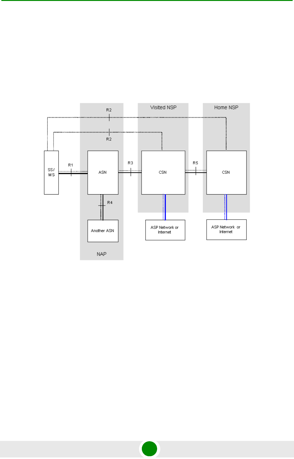
Figure 1-1 shows the basic mobile WiMAX network architecture as defined by the
WiMAX Forum NWG.
.
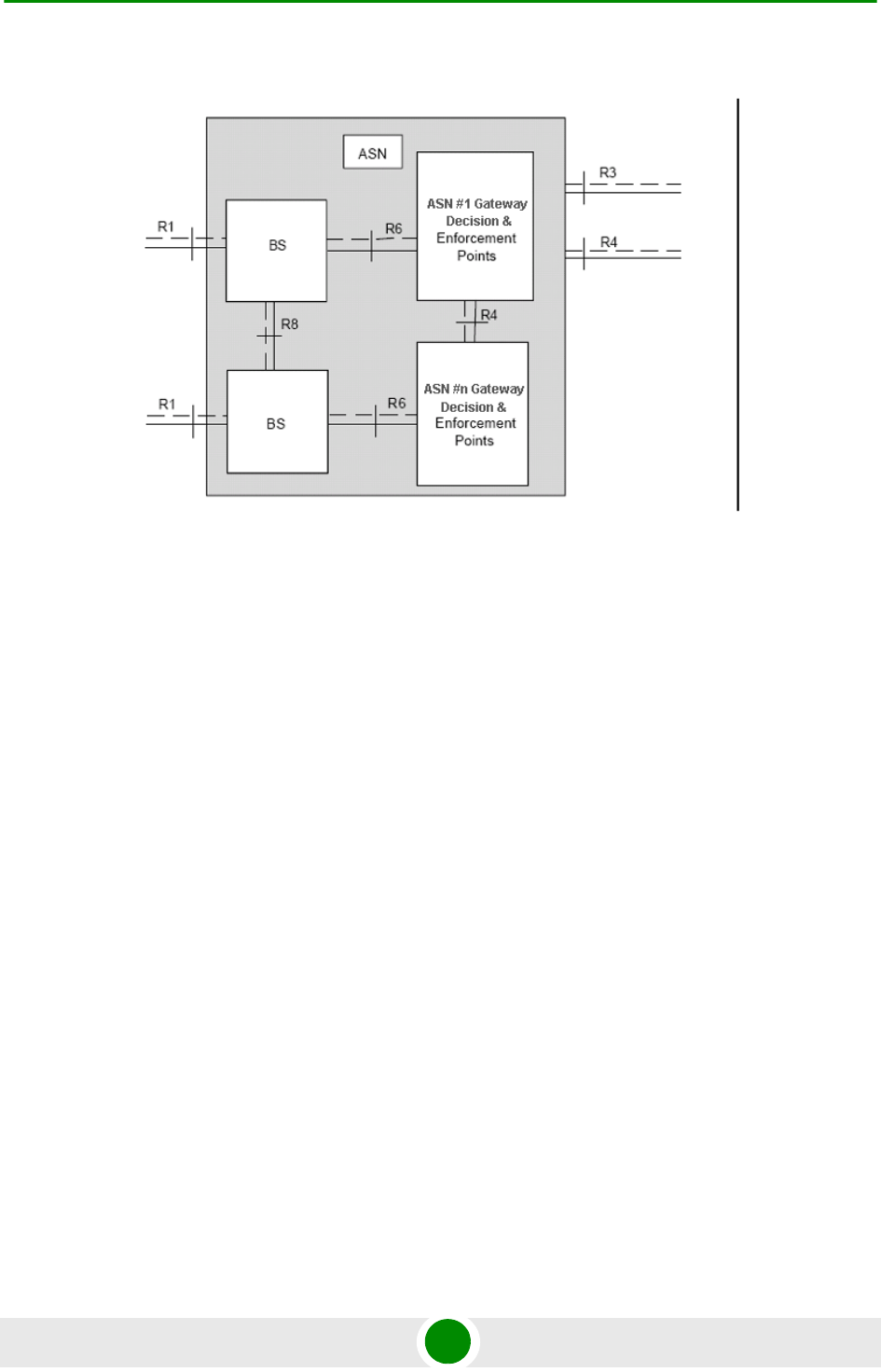
Figure 1-2 shows the ASN-GW architecture for networks with multiple ASN-GWs
(distributed network architecture).
Figure 1-1: Mobile WiMAX Network Reference Model
Chapter 1 - System Description WiMAX Network Architecture
BreezeMAX Extreme 5 System Manual
The various components and entities involved in the networking architecture are
described in the following sections:
1.2.2 Access Se rvice Ne tw ork (ASN )
An ASN is defined as a complete set of network functions needed to provide radio
access to a WiMAX subscriber. The ASN provides the following mandatory
functions:
WiMAX Layer-2 (L2) connectivity with WiMAX mobile station (MS)
Transfer of AAA messages to the WiMAX subscriber's home network service
provider (H-NSP) for authentication, authorization and session accounting for
subscriber sessions
Network discovery and selection of the WiMAX subscriber's preferred NSP
Relay functionality for establishing Layer-3 (L3) connectivity with a WiMAX MS
(i.e. IP address allocation)
Radio resource management
ASN-CSN tunneling
Figure 1-2: ASN Reference Model containing Multiple ASN-GWs

Chapter 1 - System Description WiMAX Network Architecture
BreezeMAX Extreme 6 System Manual
ASN anchored mobility
An ASN is comprised of network elements such as one or more base transceiver
stations and one or more ASN gateways. An ASN may be shared by more than one
connectivity service network (CSN).
1.2.3 Connec tivit y Se rvice Ne tw ork (CSN)
A CSN is defined as a set of network functions that provide IP connectivity
services to WiMAX subscribers. A CSN may offer the following functions:
MS IP address and endpoint parameter allocation for user sessions
Internet access
AAA proxy or server
Policy and admission control based on user subscription profiles
ASN-CSN tunneling support
WiMAX subscriber billing and inter-operator settlement
WiMAX services such as location-based services, connectivity for peer-to-peer
services, provisioning, authorization and/or connectivity to IP multimedia
services, and facilities to support lawful intercept services such as those
compliant with Communications Assistance Law Enforcement Act (CALEA)
procedures
A CSN is comprised of network elements such as routers, proxy/servers, user
databases, and inter-working gateway devices.
1.2.4 Ne tw ork Acce ss Provider (NAP)
An NAP is a business entity that provides WiMAX radio access infrastructure to
one or more WiMAX network service providers (NSPs). A NAP implements this
infrastructure using one or more ASNs.
1.2.5 Ne tw ork Ser vic e Provider (NSP)
An NSP is a business entity that provides IP connectivity and WiMAX services to
WiMAX subscribers compliant with the established service level agreement. The
NSP concept is an extension of the Internet service provider (ISP) concept,
providing network services beyond Internet access. To provide these services, an

Chapter 1 - System Description WiMAX Network Architecture
BreezeMAX Extreme 7 System Manual
NSP establishes contractual agreements with one or more NAPs. An NSP may also
establish roaming agreements with other NSPs and contractual agreements with
third-party application providers (e.g. ASP, ISP) for the delivery of WiMAX services
to subscribers. From a WiMAX subscriber standpoint, an NSP may be classified as
a home or visited NSP.
1.2.6 Base Station (BS)
The WiMAX BS is an entity that implements the WiMAX MAC and PHY in
compliance with the IEEE 802.16e standard. A BS operates on one frequency
assignment, and incorporates scheduler functions for uplink and downlink
resources.
The basic functionality of the BS includes:
IEEE 802.16e OFDMA PHY/MAC entity
R6 and optionally, if applicable, R8 functionality according to NWG definitions
Extensible Authentication Protocol (EAP) relay
Control message authentication
User traffic authentication and encryption
Handover management
QoS service flow management entity
1.2.7 ASN Gat ew ay (ASN-GW)
The ASN-GW is a network entity that acts as a gateway between the ASN and
CSN. The ASN functions hosted in an ASN-GW may be viewed as consisting of two
groups - the decision point (DP) and enforcement point (EP). The EP provides
bearer plane functions, and the DP provides non-bearer plane functions.
The basic DP functionality of the ASN-GW includes:
Implementation of EAP Authenticator and AAA client
Termination of RADIUS protocol against the selected CSN AAA server (home or
visited AAA server) for MS authentication and per-MS policy profile retrieval
Storage of the MS policy profile
Chapter 1 - System Description WiMAX Network Architecture
BreezeMAX Extreme 8 System Manual
Generation of authentication key material
QoS service flow authorization entity
AAA accounting client
The basic EP functionality of the ASN-GW includes:
Classification of downlink data into generic routing encapsulation (GRE)
tunnels
Packet header suppression functionality
DHCP functionality
Handover functionality
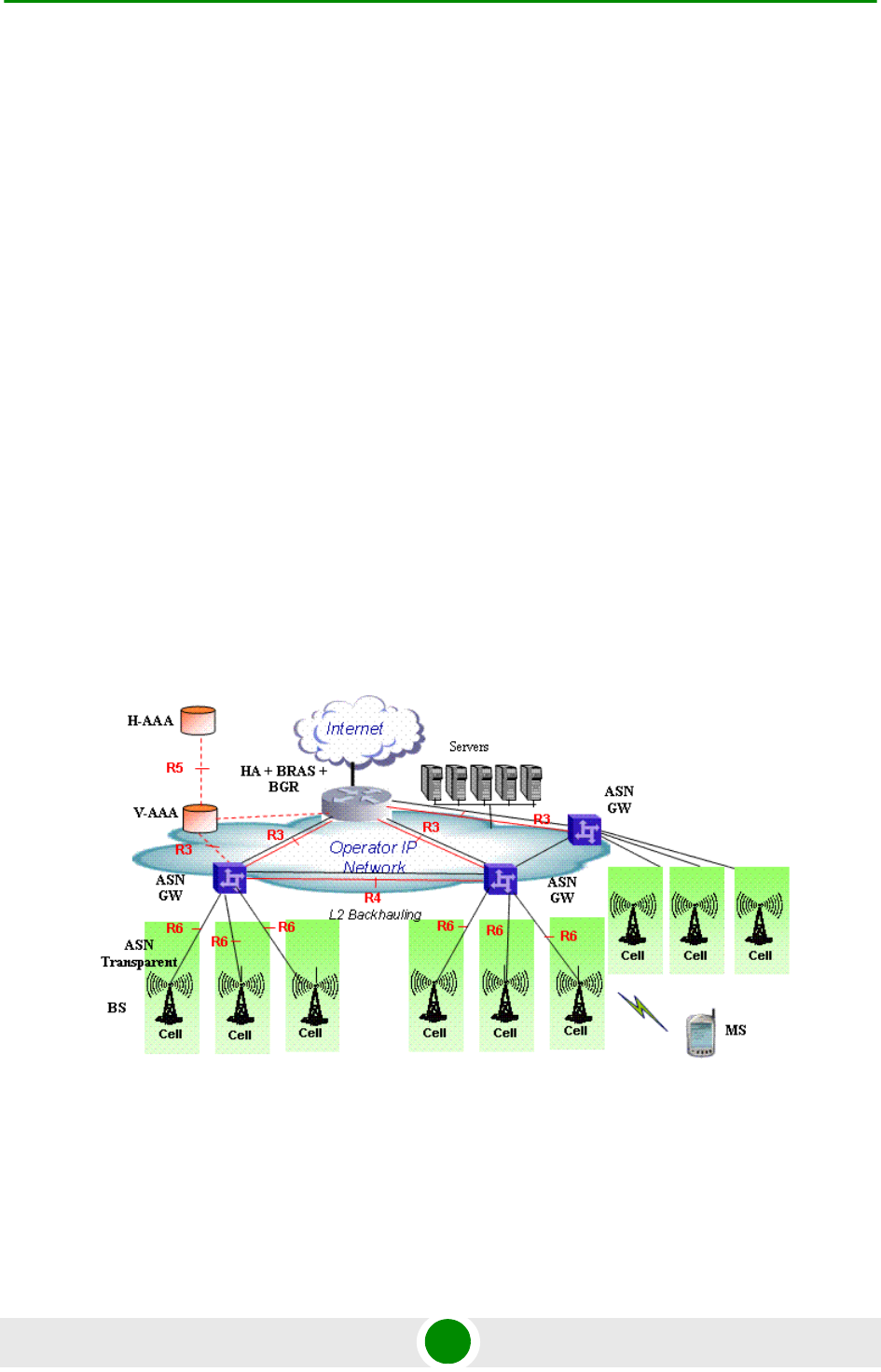
The WIMAX Forum NWG has adopted two different approaches for ASN
architecture - centralized and distributed: In the centralized approach there is at
least one central ASN-GW, and the BTS operates in transparent mode, as shown
in Figure 1-3.
Figure 1-3: Centralized Network Reference Model
Chapter 1 - System Description WiMAX Network Architecture
BreezeMAX Extreme 9 System Manual
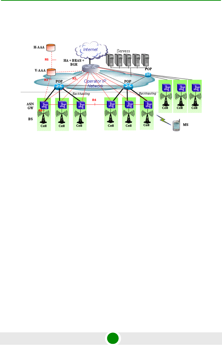
In the distributed approach, the BTS operates in ASN-GW mode, as shown in
Figure 1-4.
Alvarion believes in providing operators with the flexibility to select the mobile
WiMAX network topology that best suits their needs and existing network
architecture. Therefore, BreezeMAX Extreme is designed to support both
distributed and centralized topology approaches according to WiMAX Forum NWG
profile C.
1.2.8 Re ferenc e Points
Reference point R1 consists of the protocols and procedures between the MS
and ASN as per the air-interface (PHY and MAC) specifications (IEEE 802.16e).
Reference point R2 consists of protocols and procedures between the MS and
CSN associated with authentication, services authorization and IP host
configuration management. This reference point is logical in that it does not
reflect a direct protocol interface between the MS and CSN. The authentication
part of reference point R2 runs between the MS and CSN operated by the
home NSP, however, the ASN and CSN operated by the visited NSP may
partially process the aforementioned procedures and mechanisms. Reference
point R2 might support IP host configuration management running between
the MS and CSN (operated by either the home NSP or visited NSP).
Figure 1-4: Distributed Network Reference Model

Chapter 1 - System Description WiMAX Network Architecture
BreezeMAX Extreme 10 System Manual
Reference point R3 consists of the set of control plane protocols between the
ASN and CSN to support AAA, policy enforcement and mobility management
capabilities. It also encompasses the bearer plane methods (e.g. tunneling) to
transfer user data between the ASN and CSN.
Reference point R4 consists of the set of control and bearer plane protocols
originating/terminating in various functional entities of an ASN that
coordinate MS mobility between ASNs and ASN-GWs. R4 is the only
interoperable reference point between similar or heterogeneous ASNs.
Reference point R5 consists of the set of control plane and bearer plane
protocols for internet working between the CSN operated by the home NSP and
that operated by a visited NSP.
Reference point R6 consists of the set of control and bearer plane protocols
for communication between the BS and ASN-GW. The bearer plane consists of
an intra-ASN data path between the BS and ASN gateway. The control plane
includes protocols for data path establishment, modification and release
control in accordance with the MS mobility events.
Reference point R8 (if supported) consists of the set of control plane message
flows and optional bearer plane data flows between the base stations to ensure
a fast and seamless handover. The bearer plane consists of protocols that
allow data transfer between base stations involved in the handover of a certain
MS.
It is important to note that all reference points are logical and do not necessarily
imply a physical or even direct connection. For instance, the R4 reference point
between ASN-GWs might be implemented across the NAP internal transport IP
network, in which case R4 traffic might traverse several routers from the source to
the destination ASN-GW.
Chapter 1 - System Description BreezeMAX Extreme
BreezeMAX Extreme 11 System Manual
1.3 BreezeM AX Extre m e
1.3.1 Gene ral
BreezeMAX Extreme is a full-outdoor, all-in-one small WiMAX Base Transceiver
Station. With a range of configuration options for rural, urban and suburban
deployments, and all the benefits of Alvarion’s Open WiMAX Ecosystem, the
BreezeMAX Extreme system present an exceptionally attractive cost/performance
ratio for various needs, improving operational costs and reducing complexity.
The system is currently available in the 3.650-3.675 GHz (3.65 GHz), 4.900-5.350
GHz (4.9 GHz) and 5.470-5.950 GHz (5.4 GHz) frequency bands. Actually
available frequencies and other operational capabilities depend on the applicable
local regulations.
The Limited model BTS can simultaneously serve up to 20 CPEs, with optional
upgrades to support up to 50, 100, 150 or 250 CPEs. The “unlimited” BTS can
serve up to 250 CPEs.
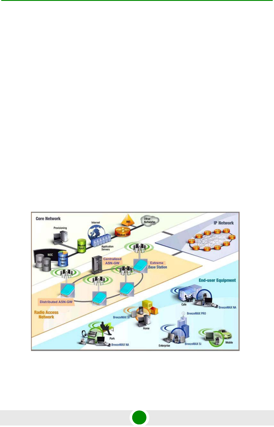
The following figure describes the end-to-end BreezeMAX Extreme based WiMAX
network:
Figure 1-5: BreezeMAX Extreme System Architecture

Chapter 1 - System Description BreezeMAX Extreme
BreezeMAX Extreme 12 System Manual
1.3.2 System Com pone nt s
The BreezeMAX Extreme system consists of the following elements:
BreezeMAX Extreme Base Transceiver Station (BTS) and associated
accessories such as GPS antenna, indoor power supply and, (if applicable)
external antennas.
Embedded ASN-GW for distributed architecture, and optionally external
ASN-GW for centralized architecture.
Optional AAA server for central authentication, authorization and accounting
services.
Outdoor and indoor CPEs supporting VoIP, Data, Bridging, tagging and
marking functionality.
AlvariSTAR central management system allowing multiple elements
management and performance monitoring.
StarACS – Automatic Configuration Server for TR-069 based management and
monitoring of CPEs.
AlvariCRAFT element management system allowing a single element
management for BTS installation/maintenance.
1.3.3 Ne tw ork Archit ectures
BreezeMAX Extreme supports different network architectures:
“Embedded Distributed ASN-GW Local Authentication”
“Embedded Distributed ASN-GW Centralized Authentication”
“External ASN-GW”
The units are supplied with an embedded ASN-GW, supporting the first two
working modes. The External ASN-GW working mode is supported by the
“unlimited” model. In the Limited model it is available only if the applicable license
is installed.
Following is a description of each of these working modes:
Chapter 1 - System Description BreezeMAX Extreme
BreezeMAX Extreme 13 System Manual
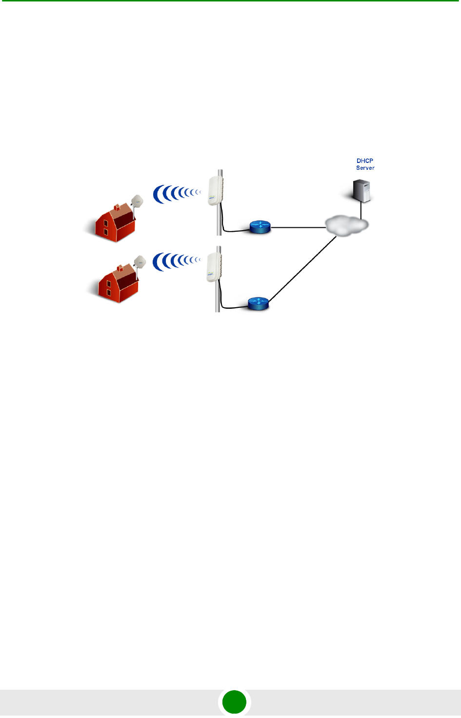
1.3.3.1 Embedded Distributed ASN-GW Local Authentication
The ASN-GW functionality resides in the BTS (distributed architecture). Service
components (Service Profiles and Service Flows) are configured in the internal
ASN-GW of each BTS. MSs list and services provisioning including authentication
are managed locally by the internal ASN-GW (AAA server not needed), based on
the SU MAC address.
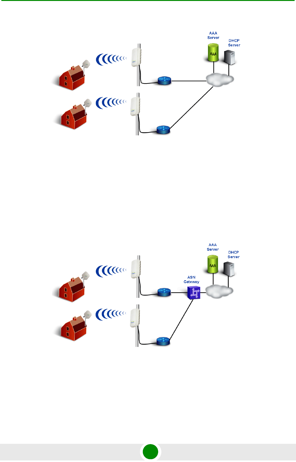
1.3.3.2 Embedded Distributed ASN-GW Centralized Authentication
The ASN-GW functionality resides in the BTS (distributed architecture). Service
components (Service Profiles and Service Flows) are configured locally in the BTS.
MS authentication and service provisioning are managed centrally by an external
AAA server, based on user credentials (user name and password).
Figure 1-6: Embedded Distributed ASN-GW Local Authentication Network Architecture
Chapter 1 - System Description BreezeMAX Extreme
BreezeMAX Extreme 14 System Manual
1.3.3.3 External ASN-GW
The ASN-GW is a separate entity (centralized architecture) that communicates
with the BTS over R6 interface. Service components (Service Profiles and Service
Flows) are configured in the external ASN-GW. MS authentication and services
provisioning are managed by a centralized AAA server, based on user credentials
(user name and password).
1.3.4 System Configurat ions
In the current release the following BTS configurations are available:
Figure 1-7: Embedded Distributed ASN-GW Centralized Authentication Network Architecture
Figure 1-8: External ASN-GW Network Architecture
Chapter 1 - System Description BreezeMAX Extreme
BreezeMAX Extreme 15 System Manual
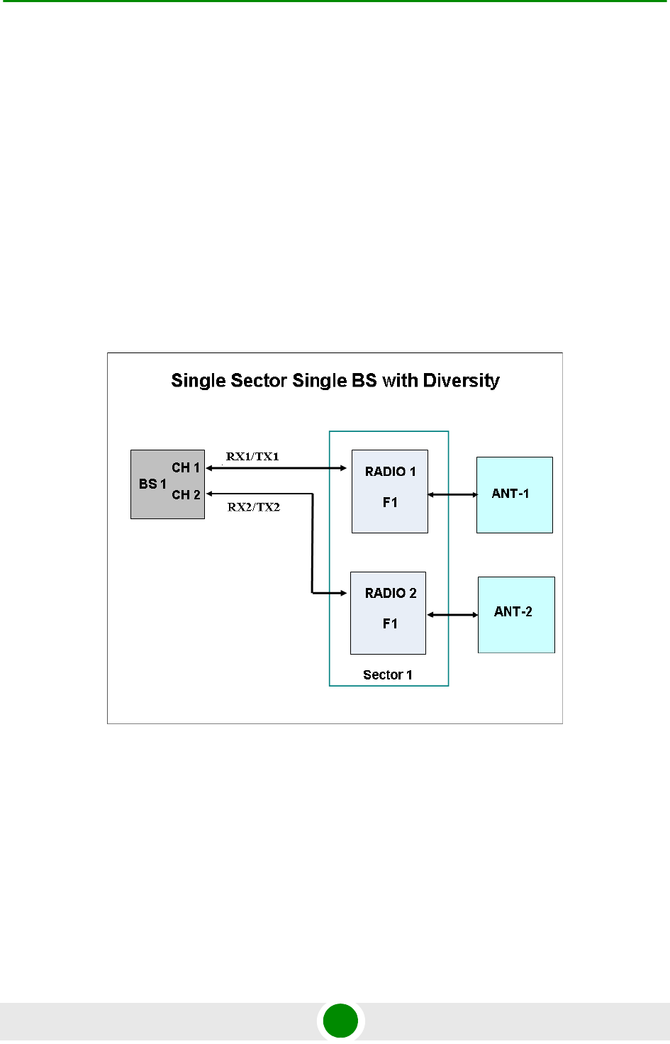
1.3.4.1 Single Sector, Second Order Diversity Configurations
Single Sector Second Order Diversity (1DIV models) units include two BSs
connected to two internal radios with either an integral dual-slant antenna or two
RF connections to external antenna(s). The basic 1DIV model units support only
the Single Sector Single BS with Diversity operation mode, using a single BS to
provide a bandwidth of 5, 7 (applicable only for 3.65 GHz units), or 10 MHz per
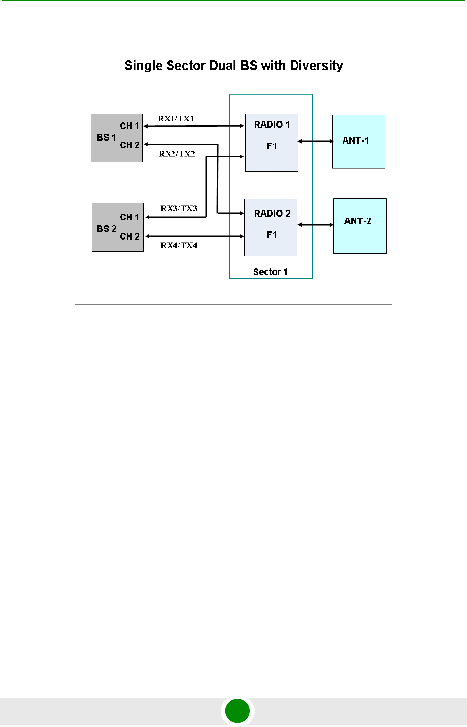
sector. 1DIV units with a license for 20 MHz bandwidth support also the Single
Sector Dual BS with Diversity operation mode, using also the second BS to
provide a total bandwidth of 14 (applicable only for 3.65 GHz units) or 20 MHz per
sector. A dual-slant antenna (internal or external) or two external antennas
support second order diversity with MIMO in the downlink and MRC in the
uplink.
Figure 1-9: Single Sector Single BS with Diversity Operation Mode
Chapter 1 - System Description BreezeMAX Extreme
BreezeMAX Extreme 16 System Manual
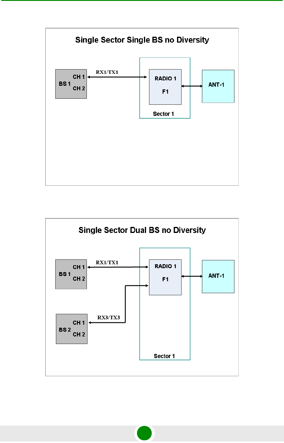
1.3.4.2 Single Sector, No Diversity Configurations
Single Sector No Diversity (1SIS model) units include two BSs connected to a
single internal radio with either an RF connection to an external antenna or (in
4.9/5.4 GHz units only) an integral dual slant antenna using the same slant as
the PRO 5100 series CPEs. The basic 1SIS model units support only the Single
Sector Single BS no Diversity operation mode, using a single BS to provide a
bandwidth of 5, 7 (applicable only for 3.65 GHz units), or 10 MHz per sector. 1SIS
units with a license for 20 MHz bandwidth support also the Single Sector Dual BS
no Diversity operation mode, using also the second BS to provide a total
bandwidth of 14 (applicable only for 3.65 GHz units) or 20 MHz per sector.
Figure 1-10: Single Sector Dual BS with Diversity Operation Mode
Chapter 1 - System Description BreezeMAX Extreme
BreezeMAX Extreme 17 System Manual
Figure 1-11: Single Sector Single BS without Diversity Operation Mode
Figure 1-12: Single Sector Dual BS without Diversity Operation Mode
Chapter 1 - System Description BreezeMAX Extreme
BreezeMAX Extreme 18 System Manual
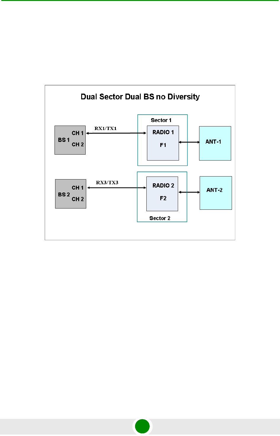
1.3.4.3 Two Sectors, No Diversity Configuration
Two Sector No Diversity (2SIS models) units include two BSs connected to two
internal radios with two RF connections to external antennas. 2SIS model units
support Dual Sector Dual BS no Diversity operation mode providing a bandwidth
of 5, 7 (applicable only for 3.65 GHz units), or 10 MHz per sector.
1.3.5 Pow er Supply
The BTS is powered from a 48V DC power source. Alvarion offers a range of indoor
AC/DC power supplies to support different power supply methods:
A PoE (Power over Ethernet) AC/DC power supply that can supply DC power
to the BTS over the Ethernet connection to the DATA DC IN/OUT connector
(this option is available only on the 5 GHz BTS units).
Direct AC/DC power supply that connects to the 48V connector of the BTS.
When using this power supply option, 48V DC power is available also on the
DATA DC IN/OUT connector, allowing power feeding to a backhauling
BreezeNet B or BreezeACCESS VL CPE.
Figure 1-13: Dual Sector Dual BS no Diversity Operation Mode

Chapter 1 - System Description BreezeMAX Extreme
BreezeMAX Extreme 19 System Manual
1.3.6 Radio Antenna s
According to radio band and configuration, BTS units are supplied with either
integral antenna(s) or with connection(s) to external antenna(s). Alvarion offers a
range of external antennas to support various deployment and coverage needs.
1.3.7 GPS Ante nna
GPS is used to synchronize the air link frames of Intra-site and Inter-site located
sectors to ensure that in all sectors the air frame will start at the same time, and
that all sectors will switch from transmit (downlink) to receive (uplink) at the same
time. This synchronization is necessary to prevent Intra-site and Inter-site sectors
interference and saturation (assuming that all neighboring sectors are operating
with the same DL/UL ratio).
The BTS includes an internal GPS receiver with hold over mechanism in case GPS
is lost or satellites synchronization was not reached. The GPS clock required is
1PPS with accuracy of 10-11 and maximum jitter of 100ns. These GPS clock
requirements can be reached by a GPS receiver when it receives at least 4
satellites. After initial synchronization, at least two satellites should be received to
maintain sufficient synchronization.
The system supports chaining of clock signals for up to six collocated units using
a single GPS antenna.
Alvarion offers two types of GPS antennas:
High Profile, active high-gain (35dBi) antenna that can be installed at a
distance of up to 25m from the BTS.
Miniature 28dBi antennas that can be installed at a distance of up to 3m from
the BTS.

Chapter 1 - System Description Specifications
BreezeMAX Extreme 20 System Manual
1.4 Spe cifications
1.4.1 Genera l M odem & Radio
1.4.2 3.65 GHz BTS
Table 1-1: General Modem & Radio Specifications
Item Description
Operation Mode TDD
Modulation OFDM modulation, 1024/512 FFT points; QPSK, QAM16, QAM64
Access Method OFDMA
FEC Convolutional Turbo Coding: 1/2, 2/3, 3/4, 5/6
Table 1-2: 3.65 GHz BTS Specifications
Item Description
Frequency 3650-3675 MHz
(actually supported frequencies depend on relevant regulations according
to the Country Code being used)
Supported Sector Bandwidth 5 MHz, 7 MHz, 10MHz, 14 MHz (2 x 7 MHz), 20 MHz (2 x 10 MHz)
Central Frequency Resolution 125 KHz
Tx Power Range 18-30 dBm
Tx Power Accuracy ±1 dB
Max. Input Power (at antenna port) -50 dBm before saturation
-10 dBm before damage
Dimensions (H x W x D) 510 x 280 x 147 mm
Weight (kg) 10.7
Power Source 40 to 60 VDC
Power Consumption Single Radio: 59W maximum
Two Radios: 92W maximum

Chapter 1 - System Description Specifications
BreezeMAX Extreme 21 System Manual
1.4.3 5 GH z BTS
Table 1-3: 5 GHz BTS Specifications
Item Description
Frequency* (see note below) 4.9 GHz Band: 4900-5350 MHz
5.4 GHz Band: 5470-5950 MHz
Supported Sector Bandwidth 5 MHz, 10MHz, 20 MHz (2 x 10 MHz)
Central Frequency Resolution 2.5 MHz @ 5 MHz sector bandwidth
5 MHz @ 10 and 20 MHz sector bandwidth
Tx Power Range (see note below) 0-21 dBm, in 1 dBm steps
Tx Power Accuracy ± 1 dB
Max. Input Power
(at antenna port)
-50 dBm before saturation
-10 dBm before damage
Dimensions (H x W x D) 510 x 280 x 147mm
Weight (kg) 10.7
Power Source 40 to 60 VDC
Power Consumpltion Single Radio: 41.5W maximum
Two Radios: 57W maximum
NOTE
Actually supported frequencies and Tx power range depend on relevant regulations according to
the Country Code being used.
Maximum supported Tx Power depend also on the configured antenna gain and in some cases also
on the bandwidth, according to the maximum allowed EIRP and spectral density specified in the
relevant regulation for the selected Country Code.
See also the Notes on Maximum Tx Power Limitations for 5 GHz Units using FCC Country Code at
the end of the Specifications section.

Chapter 1 - System Description Specifications
BreezeMAX Extreme 22 System Manual
1.4.4 Sensit ivity
Note: Following sensitivity values are for No Diversity configuration. For
configurations with diversity the sensitivity is improved by approximately 3dB.
1.4.4.1 3.65 GHz Units Sensitivity
1.4.4.2 4.9 GHz Units Sensitivity
Table 1-4: 3.65 GHz Units Sensitivity, AWGN @ PER=1%, UL Fade Margin=2dB
Modulation &
Coding
Sensitivity (dBm),
5 MHz Bandwidth
Sensitivity (dBm),
7 MHz Bandwidth
Sensitivity (dBm),
10 MHz Bandwidth
QPSK 1/2 -96 -95 -93
QPSK 3/4 -92 -91 -89
16QAM 1/2 -90 -89 -87
16QAM 3/4 -86 -85 -83
64QAM2/3 -81 -80 -78
64QAM3/4 -80 -79 -77
64QAM5/6 -78 -77 -75
Table 1-5: 4.9 GHz Units Sensitivity, AWGN @ PER=1%, UL Fade Margin=2dB
Modulation &
Coding
Sensitivity (dBm), 5 MHz Bandwidth Sensitivity (dBm), 10 MHz Bandwidth
QPSK 1/2 -96 -93
QPSK 3/4 -93 -90
16QAM 1/2 -90 -87
16QAM 3/4 -86 -83
64QAM2/3 -81 -78
64QAM3/4 -80 -77
64QAM5/6 -77 -74

Chapter 1 - System Description Specifications
BreezeMAX Extreme 23 System Manual
1.4.4.3 5.4 GHz Units Sensitivity
Table 1-6: 5.4 GHz Units Sensitivity, AWGN @ PER=1%, UL Fade Margin=2dB
Modulation &
Coding
Sensitivity (dBm), 5 MHz Bandwidth Sensitivity (dBm), 10 MHz Bandwidth
QPSK 1/2 -95 -92
QPSK 3/4 -92 -89
16QAM 1/2 -89 -86
16QAM 3/4 -85 -82
64QAM2/3 -80 -77
64QAM3/4 -79 -76
64QAM5/6 -76 -73

Chapter 1 - System Description Specifications
BreezeMAX Extreme 24 System Manual
1.4.5 3.65 GHz Antenna s
1.4.5.1 Integral 3.65 GHz Antennas
1.4.5.2 External 3.65 GHz Antennas (Optional)
Table 1-7: Integral 3.65 GHz Antennas Specifications
Item Description
90° Dual Slant 2 x 13 dBi in the 3.3-3.8 GHz band, 90°AZ x 13°EL sector antenna,
dual slant ± 45° polarization, RoHS compliant.
Table 1-8: External 3.65 GHz Antennas Specifications
Item Description
BS ANT 60V/3.3-3.8 16.5 dBi minimum in the 3.3-3.8 GHz band, 60° AZ x 7° EL, vertical polarization,
compliant with ESTI EN 302 326-3 V1.2.1 (2007-01).
76.6 x 15 x 8.7 cm, 2.2 kg. Mounting kit: 2" to 4.5" pole.
BS ANT 90V/3.3-3.8 14.5 dBi minimum in the 3.3-3.8 GHz band, 90° AZ x 7° EL, vertical polarization,
compliant with ESTI EN 302 326-3 V1.2.1 (2007-01).
76.6 x 15 x 8.6 cm, 2.2 kg. Mounting kit: 2" to 4.5" pole.
BS ANT 65/3.5 DP 2 x 16.5 dBi minimum in the 3.3-3.8 GHz band, 65°AZ x 7°EL sector antenna,
dual slant ±45° polarization, compliance with ETSI EN 302 326-3 V1.2.1 (2007-01)
and RoHS.
85.1 x 16 x 6.1 cm, 2 kg. Mounting kit: 4 to 12 cm pole.
BS ANT 90/3.5 DP 2 x 15.5 dBi minimum in the 3.3-3.8 GHz band, 90°AZ x 7°EL sector antenna,
dual slant ±45° polarization, compliance with ETSI EN 302 326-3 V1.2.1 (2007-01)
and RoHS.
85.1 x 16 x 6.1 cm, 2 kg. Mounting kit: 4 to 12 cm pole.
Omni ANT 3.6-3.8 10 dBi typical in the 3.6-3.8 GHz band, 360° AZ x 9° EL, vertical polarization.
67.5 tubular, 8 diameter, 0.29 kg, Mounting bracket: up to 50 mm pole.

Chapter 1 - System Description Specifications
BreezeMAX Extreme 25 System Manual
1.4.6 5 GH z Ante nnas
1.4.6.1 Integral 5 GHz Antennas
1.4.6.2 External 5 GHz Antennas (Optional)
Table 1-9: Integral 5 GHz Antennas Specifications
Item Description
ANT BS, 90° Dual Slant 2x14.5dBi in the 4.9-5.35 GHz band, 2x15dBi in the 5.35-5.95 GHz band,
80°(±5) AZ x 8°EL sector antenna, dual slant ±45° polarization, RoHS
compliant.
* In the 90V model only a single slant is used
Table 1-10: 5 GHz Antennas Specifications
Item Description
BS 4.9-5.9GHz Dual Slant 90° 16dBi 2x16 dBi typical in the 4.9-5.95 GHz band. 80° AZ x 6° EL sector antenna,
dual slant ±45° polarization, RoHS compliant, compliant with ETSI EN 302
326-3 V1.3.1, 55 x 25 x 1.7 cm, 1.5kg, 2"-4" pole mountable.
5.15-5.875GHz BS 60° 16dBi. 16 dBi typical in the 5.150-5.875 GHz band (15.5 dBi in the 4.900-5.150
GHz band). 60° AZ x 10° EL sector antenna, vertical polarization,
compliant with ETSI EN 302 326-3 V1.2.1 (2007-01).
43.6 x 25 x 1.0 cm, 2.2kg, 2"-3.5" pole mountable.
ANT,BS,4.9-5.875G,90V,
16.5dBi,FLAT
17 dBi typical in the 5.150-5.875 GHz band (16.5 dBi in the 4.900-5.150
GHz band). 90° AZ x 6° EL sector antenna, vertical polarization, compliant
with ETSI EN 302 326-3 V1.2.1 (2007-01).
55 x 25 x 1.1 cm, 1.5kg, 2"-3.5" pole mountable.
5.15-5.875GHz BS 120° 15dBi 15 dBi typical in the 5.150-5.875 GHz band (14.5 dBi in the 4.900-5.150
GHz band). 120° AZ x 6° EL sector antenna, vertical polarization,
compliant with ETSI EN 302 326-3 V1.2.1 (2007-01).
55.3 x 26 x 1.1 cm, 2.5kg, 2"-3.5" pole mountable.
ANT,BS,4.9-5.1G,120V, 15dBi, FLAT 15 dBi typical in the 4.900-5.100 GHz band. 120° AZ x 6.5° EL sector
antenna, vertical polarization, compliant with ETSI EN 302 326-3 V1.2.1
(2007-01). 55 x 25 x 1.7 cm, 1.5 kg, 2"-4" pole mountable.
ANT, BS, 4.9-5.875G, V9.5dBi, OMNI 9.5 dBi typical in the 4.900-5.875 GHz band. 360° AZ x 7° EL, vertical
polarization. 46.4 cm high, 2.8 cm base diameter, 0.7 kg, 1.5"-3" pole
mountable.

Chapter 1 - System Description Specifications
BreezeMAX Extreme 26 System Manual
1.4.7 Pow er Supply
1.4.7.1 High-Power AC/DC Power Supply
Table 1-11: High-Power AC/DC Power Supply Specifications
Item Description
Input Volage 90 ~ 132 / 180 ~ 264 VAC (selection by switch), 47 ~ 63 Hz.
Input AC Current (typical) 8A/115 VAC, 3.2A/230VAC
Efficiency 89% typical
Output Voltage 54 VDC
Output Current Up to 10A
Dimensions (H x W x D) 110 x 303 x 240 mm
Weight 4.75 kg

Chapter 1 - System Description Specifications
BreezeMAX Extreme 27 System Manual
1.4.7.2 PoE AC/DC Power Supply for 5 GHz BTS
1.4.8 GPS Ante nnas
1.4.9 Data Comm unic ation (Ethernet Port)
Table 1-12: PoE AC/DC Power Supply for 5 GHz BTS Specifications
Item Description
Input Volage 90 ~ 264 VAC, 47 ~ 63 Hz
Input AC Current 1.8A max. at 90 VAC
Efficiency 83% minimum
Output Voltage 55 VDC
Output Current Up to 1.27A
Dimensions (H x W x D) 33.5 x 63.5 x 160 mm
Weight 375 g
Table 1-13: GPS Antennas Specifications
Item Description
High Gain 66.2 mm high, 77.5 mm diameter, 170 g, 1”-14 thread, ROHS compliant, IP 67.
35 dB gain, power consumption 30 mA max. @ 3.3 VDC. Cable length (RG-6) up to 25m.
Operating Temperature: -40°C to +85°C.
Basic 21 mm high, 60 mm diameter, 50 g, ¾” thru-hole or bracket mount, ROHS compliant, IP 67.
28 dB gain, power consumption 15 mA max. @ 3.3 VDC. Cable length (RG-6) up to 3m.
Operating Temperature: -40°C to +85°C.
Table 1-14: Data Communication (Ethernet Port)
Item Description
Standards Compliance IEEE 802.3 CSMA/CD, IEEE 802.3u
Maximum Frame Size (including 4 CRC bytes and 4
VLAN tag bytes)
1550 bytes
Speed 10/100 Mbps, Half/Full Duplex with Auto Negotiation

Chapter 1 - System Description Specifications
BreezeMAX Extreme 28 System Manual
1.4.1 0 Configurat ion and Management
1.4.1 1 Environment al
1.4.1 2 BTS St andards Complianc e, Gene ral
Table 1-15: Configuration and Management
Item Description
Management via Data Port SNMP
Tel ne t
SNMP Agents SNMP ver 1 client
MIB II (RFC 1213), RFC2233, RFC2618, RFC2620, Private MIBs
Software upgrade Using TFTP
Configuration upload/download Using TFTP
Security Data Encryption using AES-CCM 128 bits
Table 1-16: Environmental Specifications
Type Unit Details
Operating temperature BTS -40°C to +60°C
AC/DC Power Supplyt -20°C to +70°C
Operating humidity BTS 5%-95% non condensing
AC/DC Power Supply 20%-90% non condensing
Rain and Dust Ingress Protection BTS IP 67
Table 1-17: BTS Standards Compliance, General
Type Standard
EMC ETSI EN 301 489-1/4
ETSI EN55022 Class A
FCC Part 15 Class A
Safety EN 60950-1/22
UL 60 950-1/22
Environmental ETSI 300 019-2-4 V2.2.2 Class T4.1E

Chapter 1 - System Description Specifications
BreezeMAX Extreme 29 System Manual
1.4.1 3 Notes on Maxim um Tx Pow e r Lim it ations for 5
GHz Unit s:
According to the Country Code being used the maximum allowed Tx Power
depends on the gain of antenna(s) and in some cases also on the bandwidth for
ensuring compliance with the maximum allowed EIRP and spectral density
specified in the relevant regulations.
3.65 GHz Radio FCC Part 90
FCC Part 2
RSS-197
5 GHz Radio ETSI EN 302 326
ETSI EN 301 390
ETSI EN 302 502 v1.2.1
ETSI EN 301 893 v1.5.1
FCC Part 15.247
FCC Part 15.407
FCC Part 90 Subpart Y
FCC Part 15 Subpart B
UK IR 2007
RSS-210
Lightning Protection ITU-T - K.20
EN-61000-4-5
Ethernet IEEE 802.3 CSMA/CD
IEEE 803.3u
Power Supply Interface (DC) ETSI EN 300 132-2
WiMAX IEEE 802.16-2004
IEEE 802.16e-2005
Table 1-17: BTS Standards Compliance, General
Type Standard

Chapter 1 - System Description Specifications
BreezeMAX Extreme 30 System Manual
For units operating in the 4.9 GHz band using FCC Country Code the Maximum
Tx Power at the antenna port for frequencies in the 4.940-4.990 Ghz sub-band is
19dBm, regardless of BW and number of sectors.
The following tables show the calculated maximum transmitter power level
according to relevant FCC regulations for units operating in the 5.4 GHz band
using FCC Country Code.
The required calculations are performed automatically by the BTS. Actual values
also take into account the maximum Tx power that can be supported by the
hardware (21 dBm) and supported resolution (calculated values are rounded
down to nearest integer).
Table 1-18: Maximum Tx Power @ Antenna Connector, Frequencies in the 5470-5725 MHz
Sub-Band
Antenna Type RF Chains/BW Maximum Tx Power (dBm)
Sector, 17dBi 1 RF chain /5MHz 7.7
Sector, 17dBi 2 RF chains/5MHz 4.7
Sector, 17dBi 1 RF chain /10MHz 10.7
Sector, 17dBi 2 RF chains/10MHz 7.7
Internal, 15dBi 1 RF chain /5MHz 9
Internal, 15dBi 2 RF chains/5MHz 9
Internal, 15dBi 1 RF chain /10MHz 12
Internal, 15dBi 2 RF chains/10MHz 12
Omni, 8dBi 1 RF chain /5MHz 16.7
Omni, 8dBi 2 RF chains/5MHz 13.7
Omni, 8dBi 1 RF chain /10MHz 19.7
Omni, 8dBi 2 RF chains/10MHz 16.7
Table 1-19: Maximum Tx Power @ Antenna Connector, Frequencies in the 5725-5850 MHz
Sub-Band
Antenna Type and Gain Maximum Tx Power (dBm)
Internal, dual slant 15dBi 21
Omni, 9.5dBi 24.2
Sector, 17dBi 19.7

2
Chapter
Installation

Chapter 2 - Installation Site Deployment Options
BreezeMAX Extreme 33 System Manual
2.1 Site Deploym ent Options
2.1.1 BTS Inst allat ion Opt ions
The BreezeMAX Extreme BTS can be installed on straight or angled poles (±45°
from upward position) and on a flat surface, such as walls. Each BTS package
includes a tilt bracket that allows pole or wall mount deployment with up/down
tilt of +7.5° to -10°, and rotation of ±45°.
2.1.2 Ant enna Options
The BTS (depending on the model) is offered with either integrated antenna or
external antenna. The following table details the options for each model.
For external antenna connection details refer to Section 2.6.
2.1.3 GPS Opt ions
The BTS has an integrated GPS receiver and requires only a GPS antenna to
connect to it. Two antenna kits are available from Alvarion: a basic GPS antenna
kit, and a high gain GPS antenna kit.
When deploying a single sector without any adjacent systems, the BTS may be set
to operate without GPS synchronization. A multi-sector deployment requires
either one of the following GPS options:
For a site with a single BTS - the GPS antenna kit
CAUTION
ONLY experienced installation professionals who are familiar with local building and safety codes
and, wherever applicable, are licensed by the appropriate government regulatory authorities should
install outdoor units and antennas.
Failure to do so may void the BreezeMAX Extreme product warranty and may expose the end user
or Service Provider to legal and financial liabilities. Alvarion and its resellers or distributors are not
liable for injury, damage or regulation violations associated with the installation of outdoor units or
antennas.
Table 2-1: Antenna Configuration Options
Model Integrated Antenna External Antenna
Single sector MIMO Yes Yes
Single sector SISO Yes Yes
Dual sector SISO No Yes
Chapter 2 - Installation Site Deployment Options
BreezeMAX Extreme 34 System Manual
For a multi-BTS site - using the GPS chaining option
The GPS and external antenna should be installed above the BTS. Make sure to
allow access to all components and consider the location of power source.
2.1.4 Pow e r Fe eding Options
There are several power feeding options for BTS including either (Power over
Ethernet (PoE) or direct 48VDC. An additional option is available for backhauling
CPE connectivity powered by the BTS. See also “Indoor Power Supply Installation”
on page 54.
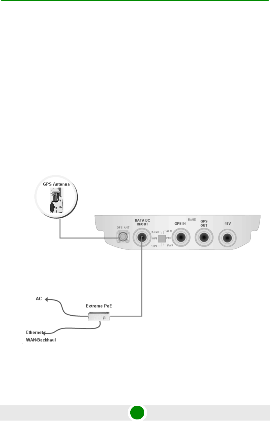
2.1.4.1 PoE Power Feeding
A typical site deployment with PoE power feeding a single PoE indoor-outdoor
cable (8-wires CAT5 shielded cable, max. 70m) connects the BTS to a power
supply unit, which is connected to an AC source and to Ethernet WAN/Backhaul.
See “PoE AC/DC Power Supply” on page 54.
Figure 2-1: PoE Power Feeding Option
Chapter 2 - Installation Site Deployment Options
BreezeMAX Extreme 35 System Manual
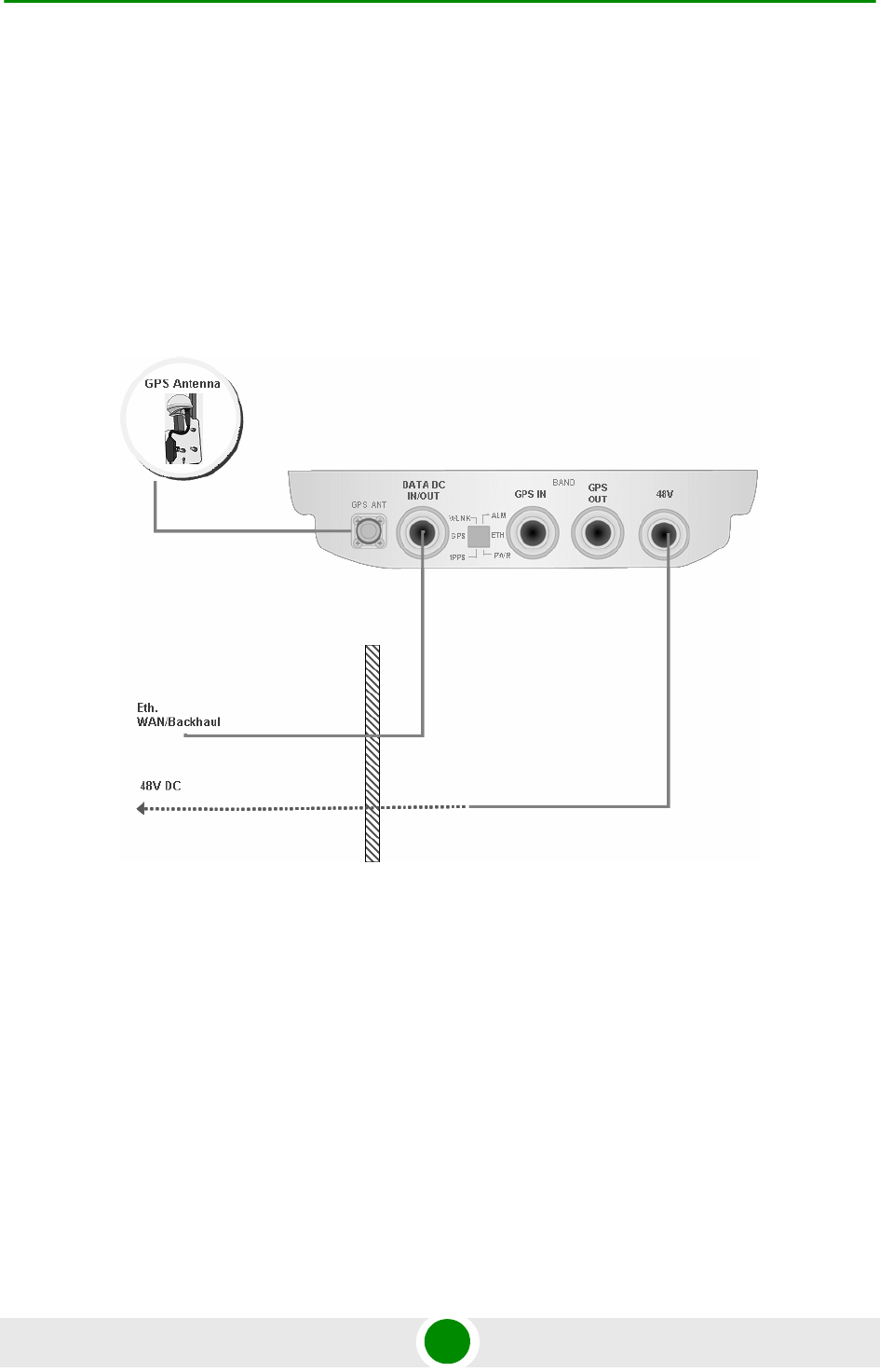
2.1.4.2 48VDC Power Feeding
In a typical site deployment with direct 48VDC power feeding, the BTS is
connected with two different cables:
A DC cable feeding the 48V DC
A DAT cable (4wires CAT5 shielded cable) connecting the BTS to the
backhaul/WAN
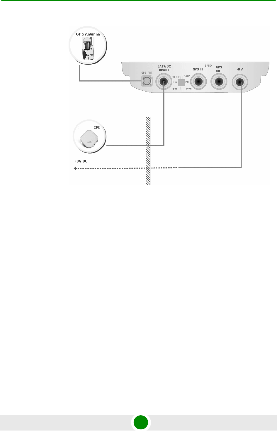
2.1.4.3 48VDC Power Feeding + Backhaul CPE
A unique option allows connecting and feeding a backhaul Alvarion CPE (e.g.
BreezeNET B-100) directly to the BTS. In this case the BTS is connected by a DC
cable to the 48V DC source. The BTS feeds power to the backhaul CPE. The cable
connecting between the backhaul CPE and BTS is a CAT5 shielded outdoor cable.
Figure 2-2: 48VDC Power Feeding Option
Chapter 2 - Installation Site Deployment Options
BreezeMAX Extreme 36 System Manual
Figure 2-3: 48VDC Power Feeding including Backhaul CPE Option
Functions as PoE
Feeding to Alvarion
Backhaul CPE
I

Chapter 2 - Installation BTS Installation
BreezeMAX Extreme 37 System Manual
2.2 BT S Installation
2.2.1 Inst allat ion Re quireme nts
2.2.1.1 Packing List
BTS (weight: 10.7 Kg.)
Mounting kit (for 1.5''-4'' poles) including the tilt bracket and carriage
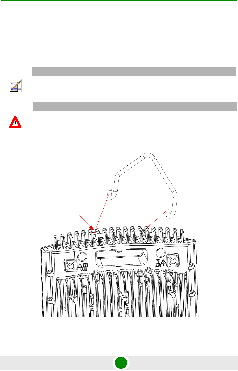
Sealing Gland Fastening Tool
Carrying hook
2.2.1.2 Optional Components
Kit including 4 metal bands for mounting on poles larger than 4''
2.2.1.3 Additional Installation Requirements
The following items are also required to install the BTS:
Ethernet cable*. Not applicable for 5 GHz units using PoE power supply
option. Available in various lengths.
Power Supply:
»PoE Power Supply with a Data and Power (indoor-outdoor) CAT5 cable*
(applicable only for 5 GHz units, available in various lengths), or:
»High power AC/DC Power Supply unit and DC power cable* (available in
various lengths).
Antenna(s)* and RF cable(s)* for connecting the antenna(s) to the BTS.
(applicable for units without integral antennas).
Grounding cable with an appropriate termination.
Chapter 2 - Installation BTS Installation
BreezeMAX Extreme 38 System Manual
One of the following GPS options (see “GPS Installation” on page 49):
»High-Gain GPS Antenna with mounting kit, 25m cable and two lightning
arrestors. Or:
»Basic GPS Antenna kit including mounting kit, 3m cable and one lightning
arrestor.
For GPS chaining, if applicable: Outdoor CAT5 cable(s)
Installation tools and materials.
For wall mount installation - four suitable dowels and screws.
2.2.1.4 Pole Mounting Kit
Carriage
Tilt bracket
Two Heavy duty metal clamps
4 x Threaded rods
10 x M8X20 screws
18 x M8 flat washers
8 x M8 nuts
14 x M8 spring washers
For poles larger than 4'' - additional kit containing 4 metal bands
NOTE
Items marked with an asterisk (*) are available from Alvarion.
Chapter 2 - Installation BTS Installation
BreezeMAX Extreme 39 System Manual
2.2.2 Assembling the T ilt Bra cket on the BT S
The tilt bracket is attached and fastened to the BTS and then hung on the
carriage. After hanging the BTS on the carriage, tilt and rotate the BTS as required
before fastening the screws. The Tilt Bracket supports +7.5°/-10° tilting and ±45°
vertical plane rotation. The BTS has to be vertical to the ground.
NOTE
Install the unit with the bottom panel, including the LEDs, facing downward. Note the direction
arrows (UP) on the sides of the BTS.
CAUTION
The weight of BTS is 10.7 Kg and the weight of the Pole Mounting Kit is approximately 5 kg. Be sure
to plan the installation accordingly. It is recommended to use the supplied carrying hook (see
Figure 2-4) and a harness to lift the units.
Install the unit using the supplied kit only.
Figure 2-4: Carrying Hook
Hook
Holes for using
the hook
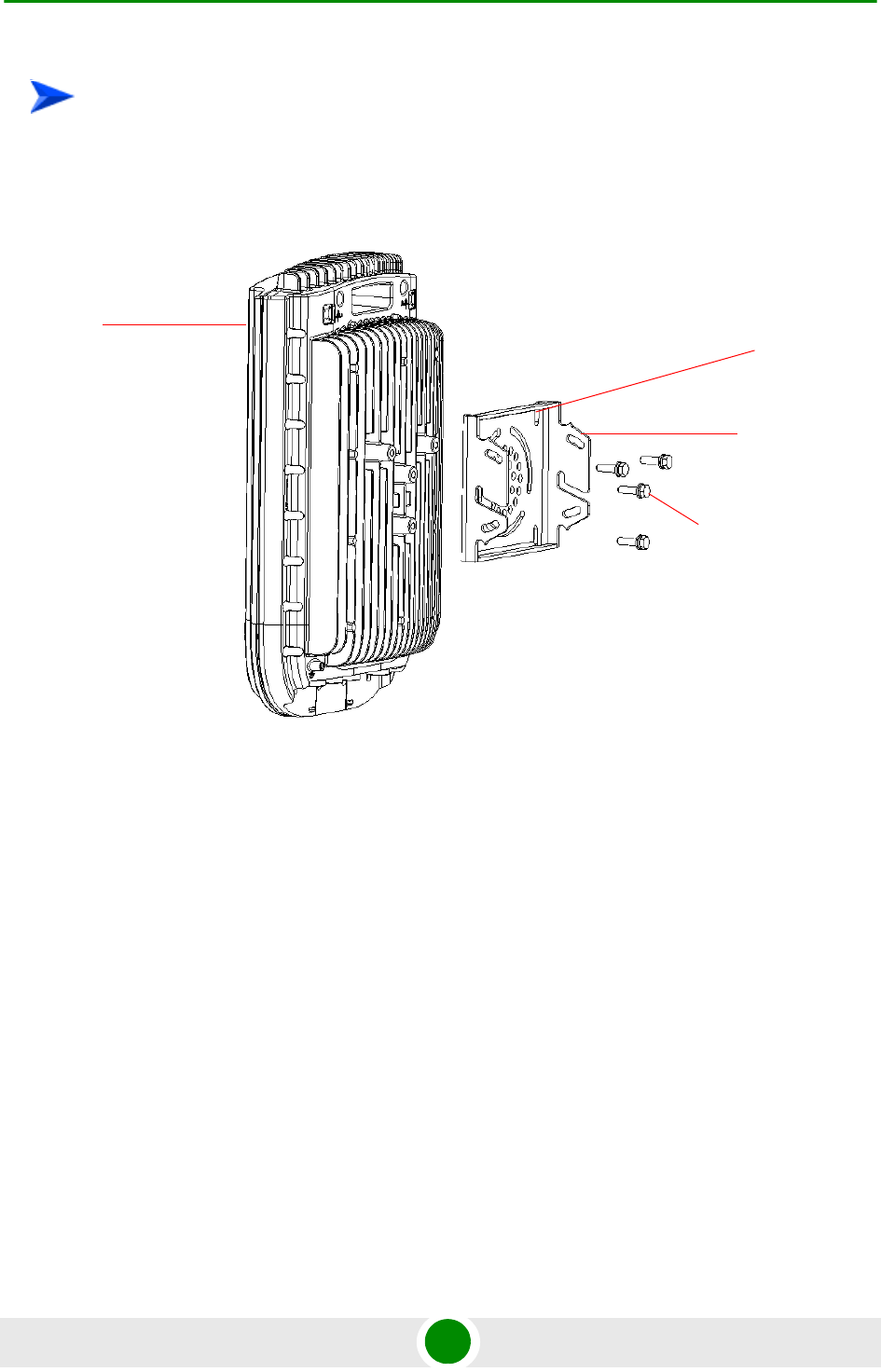
Chapter 2 - Installation BTS Installation
BreezeMAX Extreme 40 System Manual
Place the tilt bracket on the BTS and fasten its M8 screws (see Figure 2-5 and
Figure 2-6). Apply torque of 80 [Lib*In] = 9 [N*m]
To assemble the bracket on the BTS:
Figure 2-5: Assembling the Tilt Bracket on the BTS
Tilt bracket
BTS
M8X20 screws
Carrying
grooves
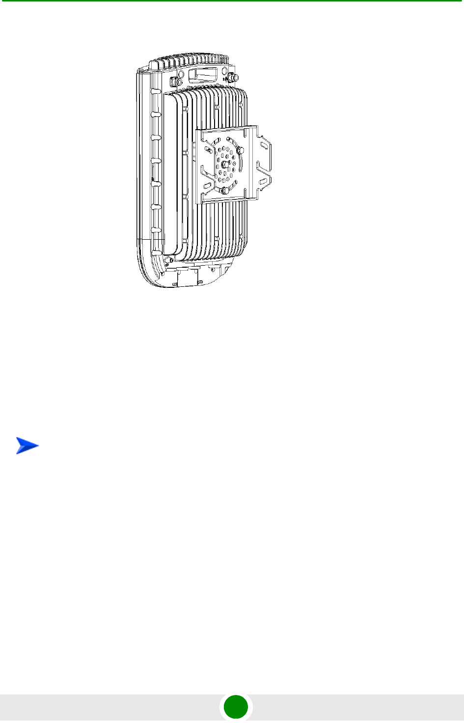
Chapter 2 - Installation BTS Installation
BreezeMAX Extreme 41 System Manual
2.2.3 Inst alling a Lightning Arre stor
The lightning arrestor near the BTS is mandatory for protecting the BTS from
lightning coming through the GPS antenna (both basic and High-Gain GPS units).
If you use a High-Gain GPS antenna with a cable longer than 3m, an additional
lightning arrestor must be installed near the GPS.
1 Install the lightning arrestor (part of the GPS Kit, see “GPS Installation” on
page 49) at the designated location at the bottom of the carriage (see
Figure 2-7).
Figure 2-6: Tilt Bracket Installed on BTS
To install a lightning arrestor on the carriage:
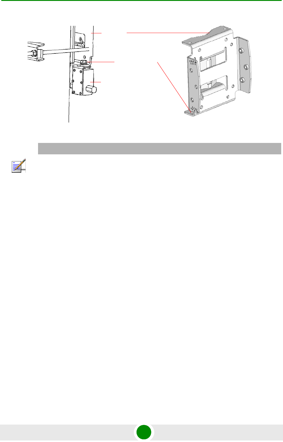
Chapter 2 - Installation BTS Installation
BreezeMAX Extreme 42 System Manual
2.2.4 Inst alling the BTS on a Pole
The BTS can be installed on poles of various sizes, using the supplied carriage
(see Figure 2-8). For poles of 1.5''-4'' in diameter, use the supplied metal clamps.
For poles larger than 4'' use metal bands.
Figure 2-7: Installing the Lightning Arrestor on the Carriage
NOTE
Some units are supplied with a separate pole-mounting bracket for the lightning arrestor. Instead
of attaching the lightning arrestor to the carriage, install this bracket on the pole as close to the
BTS as possible, allowing connecting the lightning arrestor to the BTS’s GPS connector.
The lightning arrestors supplied within the GPS kit are not included in the warranty cover
provided for the GPS unit. Additional lightning arrestors can be ordered separately
Lightning Arrestor
Carriage
Hole for lightning
arrestor
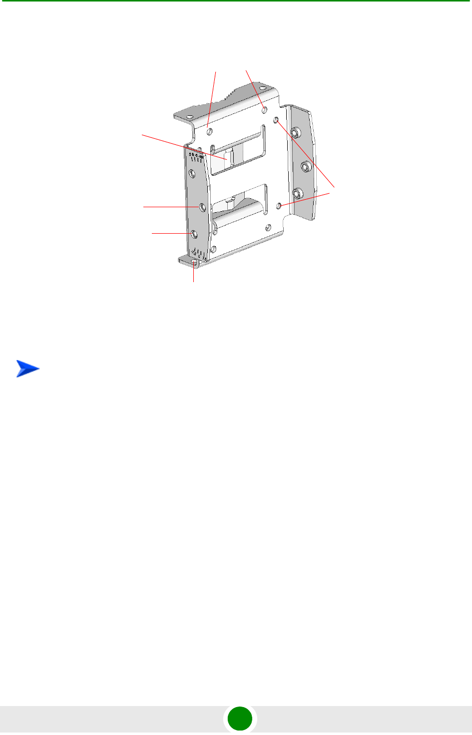
Chapter 2 - Installation BTS Installation
BreezeMAX Extreme 43 System Manual
1 Assemble the tilt bracket on the BTS and fasten its four screws (see
“Assembling the Tilt Bracket on the BTS” on page 39).
2 Install a lightning arrestor on the carriage as described in “Installing a
Lightning Arrestor” on page 41.
3 Thread the four rods through the carriage.
4 Attach the carriage and the clamps to the pole and tighten on both sides using
the supplied washers, spring washers and nuts. Apply torque of
80 [Lib*In] = 9 [N*m].
5 Insert the tilt control screws into the middle-side hole of the carriage on both
sides.
Figure 2-8: BreezeMAX Extreme Pole Mount Carriage
To install the Carriage on a 1.5''-4'' pole:
Holes for pole
mounting rods (x4)
Holes for wall
mounting screws (x4)
Groove for
metal bands
Holes for fastening
screws (x4)
Tilt control
screws (x2)
Holes for lightning
arrestor (x4)
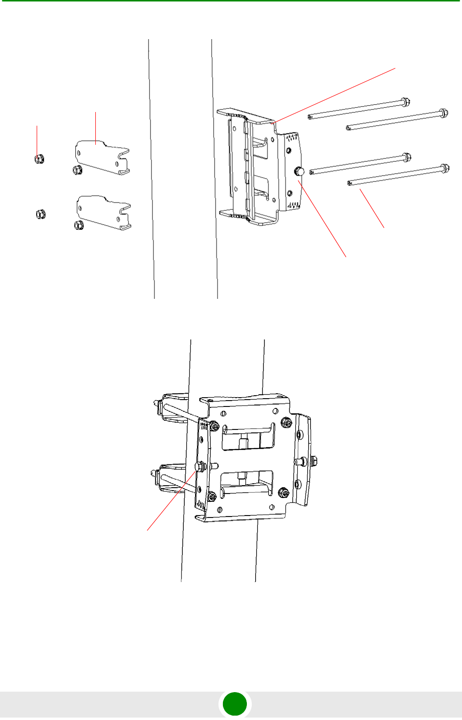
Chapter 2 - Installation BTS Installation
BreezeMAX Extreme 44 System Manual
Figure 2-9: Assembling BTS Carriage and Clamps
Figure 2-10: BTS Carriage and Clamps Installed
Carriage
Till control screw
Clamps
Rods
Nuts, washers
and spring
washers
Tilt control
screw
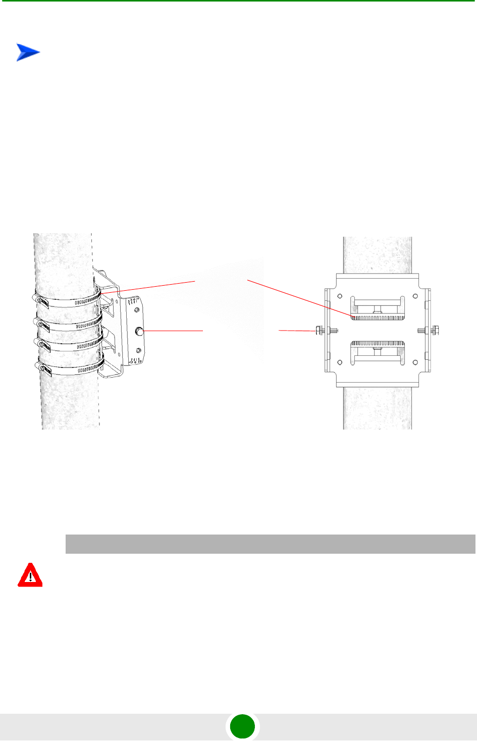
Chapter 2 - Installation BTS Installation
BreezeMAX Extreme 45 System Manual
1 Assemble the tilt bracket on the BTS and fasten its four screws (see
“Assembling the Tilt Bracket on the BTS” on page 39).
2 Thread the four metal bands through the grooves on the BTS carriage and
fasten them (see Figure 2-11).
3 Attach the carriage to the pole and fasten the metal bands (see Figure 2-11).
4 Insert the tilt control screws into the middle-side hole of the carriage on both
sides (Figure 2-11).
2.2.5 Mounting t he BT S on the Carria ge
At this stage, after mounting the BTS on the carriage, use the Tilt bracket to tilt
and rotate the BTS as required.
To install the Carriage on a pole larger than 4'':
Figure 2-11: Installed Carriage with Metal Bands
CAUTION
The weight of BTS is 10.7 Kg and the weight of the Pole Mounting Kit is approximately 5 kg. Be sure
to plan the installation accordingly. It is recommended to use a harness to lift the units.
Install the unit using the supplied kit only.
Tilt control screws
Metal bands
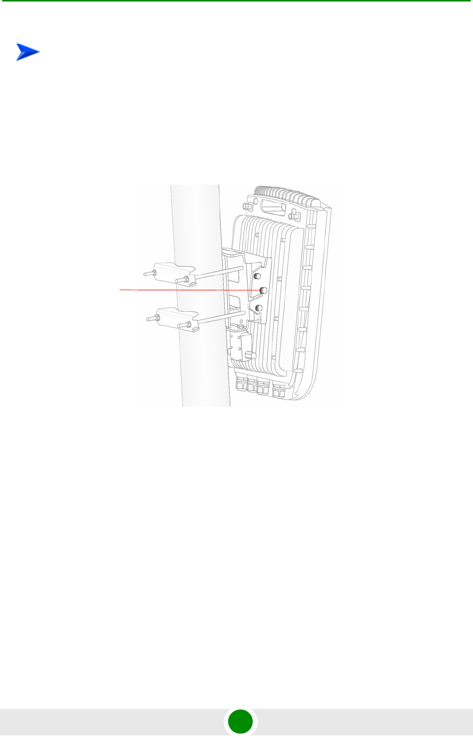
Chapter 2 - Installation BTS Installation
BreezeMAX Extreme 46 System Manual
1 Hang the BTS with the tilt bracket on the tilt control screws of the BTS
carriage.
2 Attach and fasten all the screws at both sides of the BTS carriage . Do not over
tighten.
To mount the BTS on the carriage:
Figure 2-12: BTS Mounted on a 1.5''-4'' Pole (with Clamps)
Tilt control screw
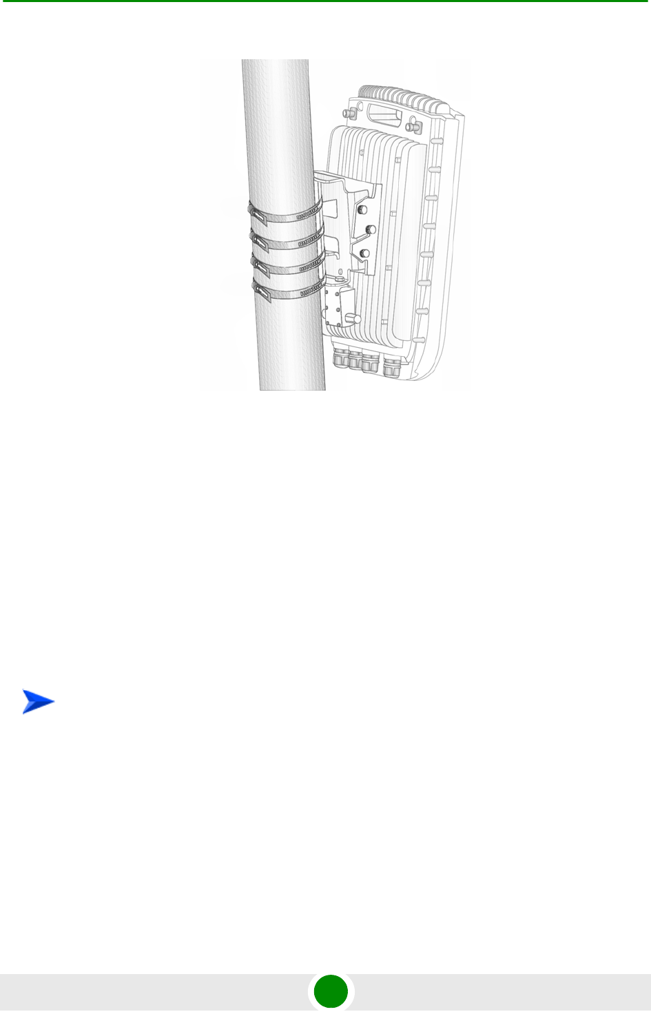
Chapter 2 - Installation BTS Installation
BreezeMAX Extreme 47 System Manual
3 If required, slightly release the tilt bracket screws to enable rotation, and the
tilt control screws to enable tilting; Adjust the BTS position and tighten the
screws. Apply torques of 45 [Lib*In.] = 5 [N*m] to the M6 Tilt-control screws,
and 80 [Lib*In] = 9 [N*m] to the M8 screws.
2.2.6 Wall M ount Inst allat ion
The BreezeMAX Extreme BTS can be installed on walls or any flat surface. This
requires attaching and fastening the carriage with the BTS to the wall using
suitable securing means (not supplied) and then tilting and rotating the BTS as
required. The location of the screws should be planned with maximum precision.
1 Assemble the tilt bracket on the BTS and fasten its four screws (see
“Assembling the Tilt Bracket on the BTS” on page 39).
2 If you use a High-Gain GPS antenna with a cable longer than 3m, install a
lightning arrestor on the carriage as described in “Installing a Lightning
Arrestor” on page 41.
3 Place the carriage on the wall and mark the exact location of the holes to drill.
Figure 2-13: BTS Mounted on a Pole Larger than 4'' (with Metal Bands)
To install the BTS on a wall:
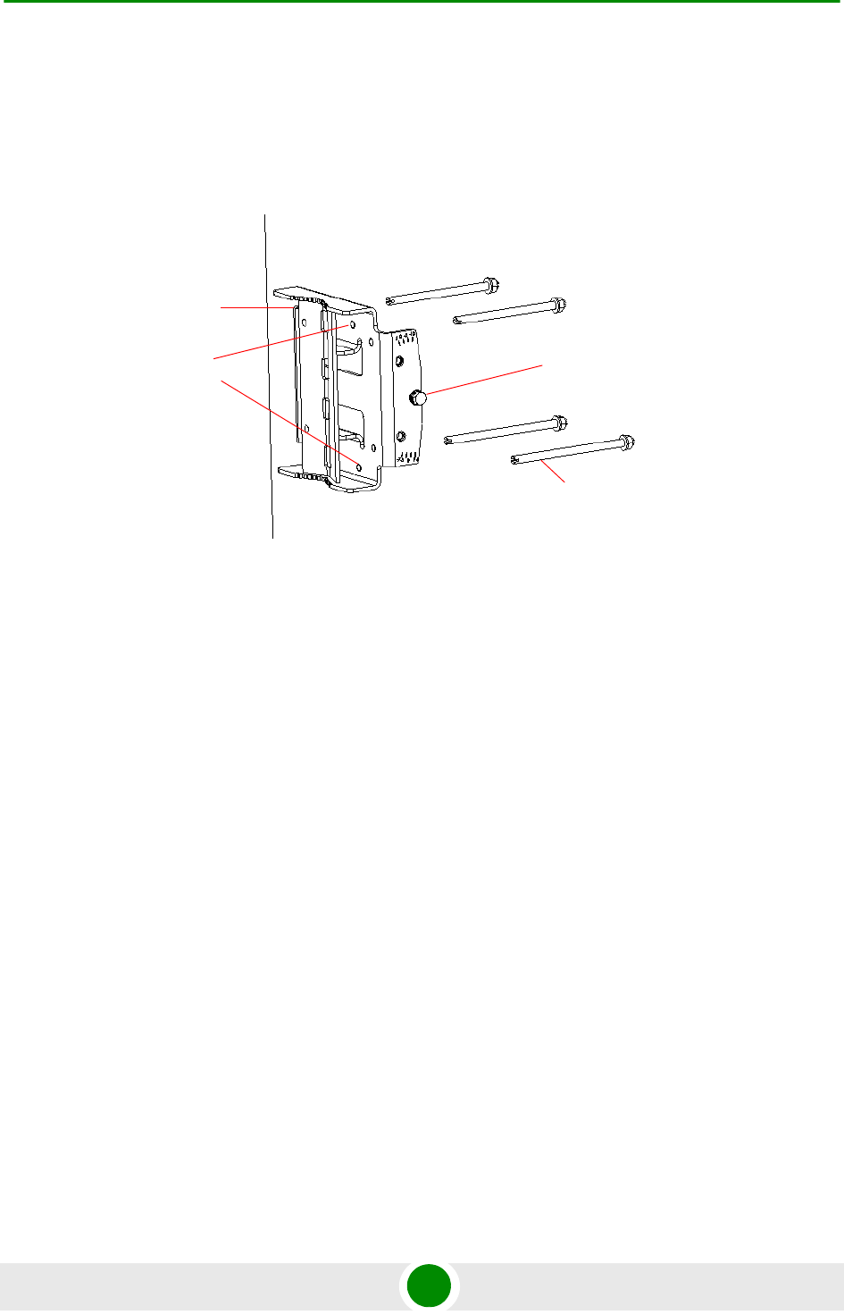
Chapter 2 - Installation BTS Installation
BreezeMAX Extreme 48 System Manual
4 Drill the holes, and use four metal dowels and screws to affix the carriage to
the wall.
5 Insert the tilt control screws into the middle-side hole of the carriage on both
sides (see Figure 2-14).
6 Hang the BTS with the tilt bracket on the tilt control screws of the BTS
carriage.
7 Attach and fasten all the screws at both sides of the carriage (see Figure 2-14).
Do not over tighten.
8 If required, slightly release the tilt bracket screws to enable rotation, and the
tilt control screws to enable tilting; Adjust the BTS position and tighten the
screws.
Figure 2-14: Mounting the Carriage on the Wall
Carriage
Till control screw
Holes for
wallmount
screws (to be
fastened using
dowels

Chapter 2 - Installation GPS Installation
BreezeMAX Extreme 49 System Manual
2.3 GPS Installat ion
Alvarion offers two types of GPS antenna (basic and high-gain) that can be
installed at a distance of up to 25m (high-gain) or 3m (basic) from the BTS (with
the required mounting kit and connecting cable). Refer to “GPS Antennas” on
page 27 in the Specifications section for more information.
When installing a site with more than one BTS (e.g. a 3 or 4 sector deployment),
you may leverage GPS chaining capability of the BreezeMAX Extreme BTS. The
system supports chaining of clock signals for up to 4 collocated units using a
single GPS antenna: One BTS is connected to a GPS antenna, and the other BTSs
are chained (up to 4 additional BTS) to the first BTS using an outdoor CAT5 cable.
2.3.1 Inst allat ion Re quireme nts
The High-gain GPS antenna is installed using a specially designed bracket and
a 25m cable. A second lightning arrestor is required with this configuration in
addition to the lightning arrestor already assembled on the BTS carriage (see
“Installing a Lightning Arrestor” on page 41).
The Basic GPS antenna is installed using a specially designed bracket and a
3m cable. No lightning arrestor is required with this configuration in addition
to the lightning arrestor already assembled on the BTS carriage.
For GPS chaining: outdoor CAT5 cable(s)
2.3.2 Packing List
GPS Mounting Kit: One of the following options:
Basic GPS Antenna
»28 dBi GPS antenna
»3m cable
»Pole mount bracket
»Two metal bands
»One Lightning Arrestor with 0.5m cable, including screws, washer, and
spring washer (UNC10-32)
Chapter 2 - Installation GPS Installation
BreezeMAX Extreme 50 System Manual
High gain GPS Antenna
»High gain (35 dBi) antenna
»25m cable
»Pole mount bracket
»Two metal bands
»Carriage mounting bracket
»Two Lightning Arrestors with 0.5m cables, including screws, washers, and
spring washers (2 x UNC10-32)
2.3.3 Inst alling the GPS
1 Place the bracket on a flat surface and thread the GPS antenna through the
hole at the top of the bracket. Hand-tighten the fastening nut.
2 Connect one end of the 0.5 m cable to the lightning arrestor and the other end
to the GPS ANT connector on the BTS.
3 Connect one end of the GPS 3m cable to the lightning arrestor, and the other
end to the GPS antenna.
NOTE
The lightning arrestors supplied within the GPS kit are not included in the warranty cover provided
for the GPS unit.
Additional lightning arrestors can be ordered separately.
To install the basic GPS antenna:
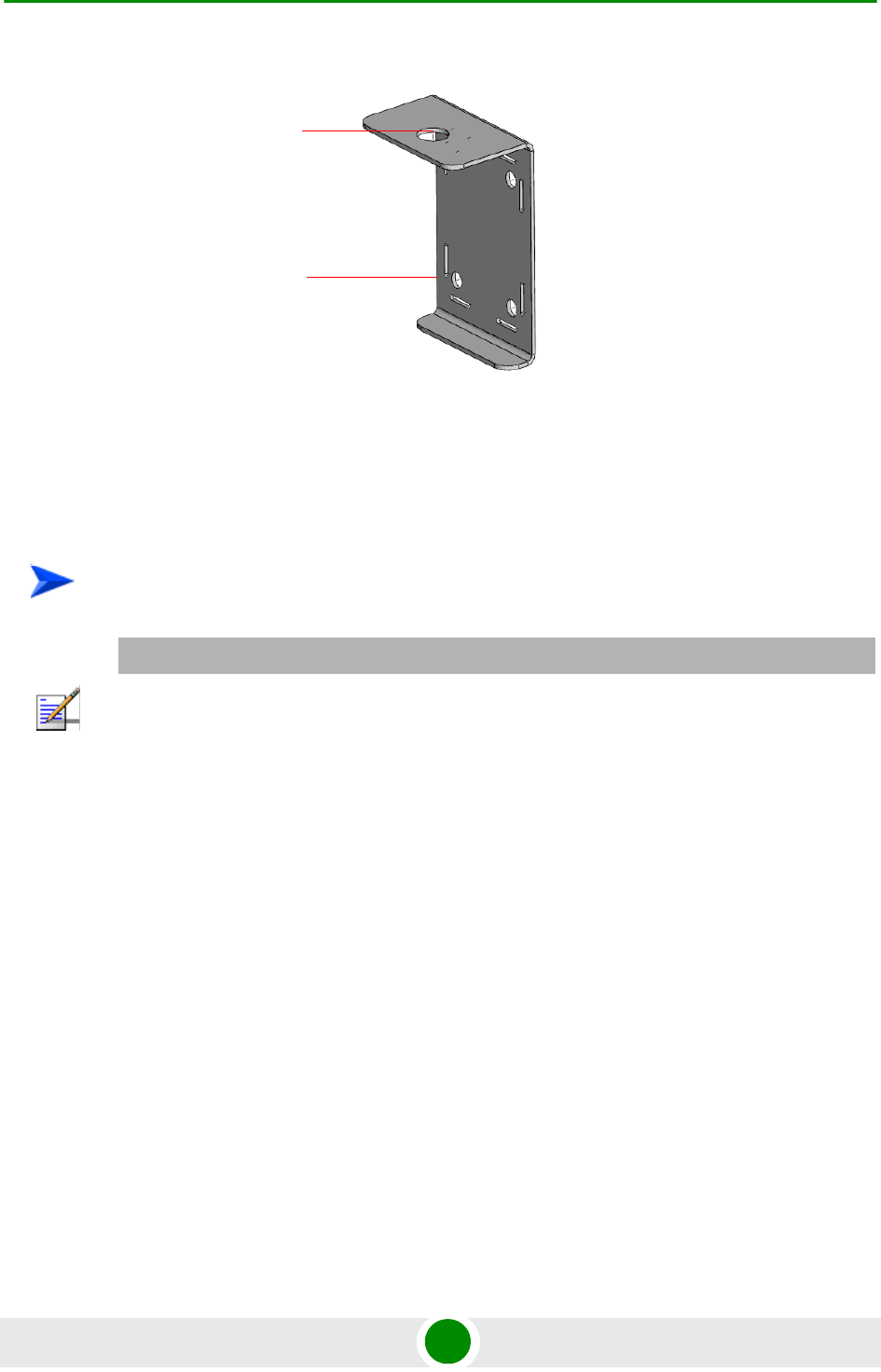
Chapter 2 - Installation GPS Installation
BreezeMAX Extreme 51 System Manual
4 Use the supplied metal bands to assemble the bracket on a pole.
5 Fix the cable onto the pole using plastic strips.
1 Place the bracket on a flat surface and thread the GPS antenna through the
3/4" hole of the bracket. Hand-tighten the fastening nut.
2 If you use a GPS cable longer than 3m, assemble the lightning arrestor on the
bracket, with the screws facing the bracket.
3 Connect one end of the 0.5 m cable to the lightning arrestor and the other end
to the GPS antenna.
Figure 2-15: Bracket for Basic GPS
To install the high-gain GPS antenna:
NOTE
Do not over-tighten or use a tool for tightening the cables, to avoid stripping the connectors.
Hole for GPS
antenna
Holes for
metal bands
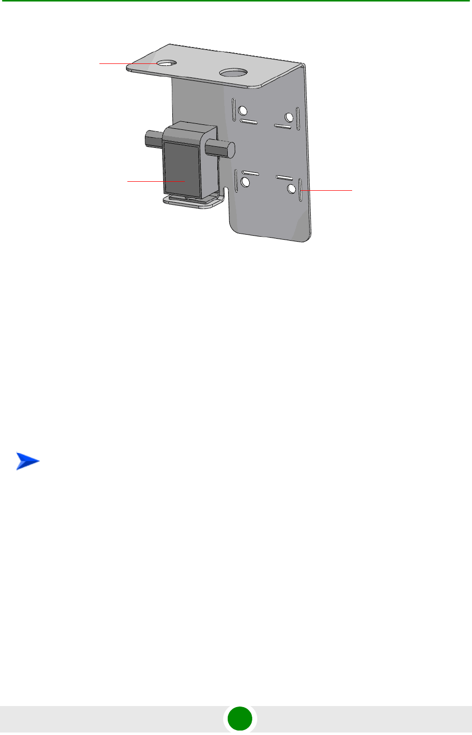
Chapter 2 - Installation GPS Installation
BreezeMAX Extreme 52 System Manual
4 Use the 25m GPS cable to connect the lightning arrestor on the GPS bracket to
the second lightning arrestor installed near the BTS (see “Installing a
Lightning Arrestor” on page 41). Connect this second lightning arrestor to the
GPS ANT connector on the BTS.
5 Hand-tighten the connector on the interface cable using the locking ring for
securing the connection.
6 Use the supplied metal bands to assemble the bracket on a pole.
7 Fix the cable onto the pole using a plastic strip.
Refer to Figure 2-17.
1 Connect one end of the CAT5 cable to the GPS OUT connector of the BTS with
the GPS antenna, and the other end to the GPS IN connector of the chained
(target) BTS.
2 To chain an additional BTS, connect one end of the CAT5 cable to the GPS
OUT connector of the chained BTS, and the other end to the GPS IN connector
of the added (target) BTS.
Figure 2-16: Bracket for High-Gain GPS
To connect BTSs in GPS chaining:
Hole for
High-gain
GPS antenna
Lightning
arrestor Holes for
metal bands
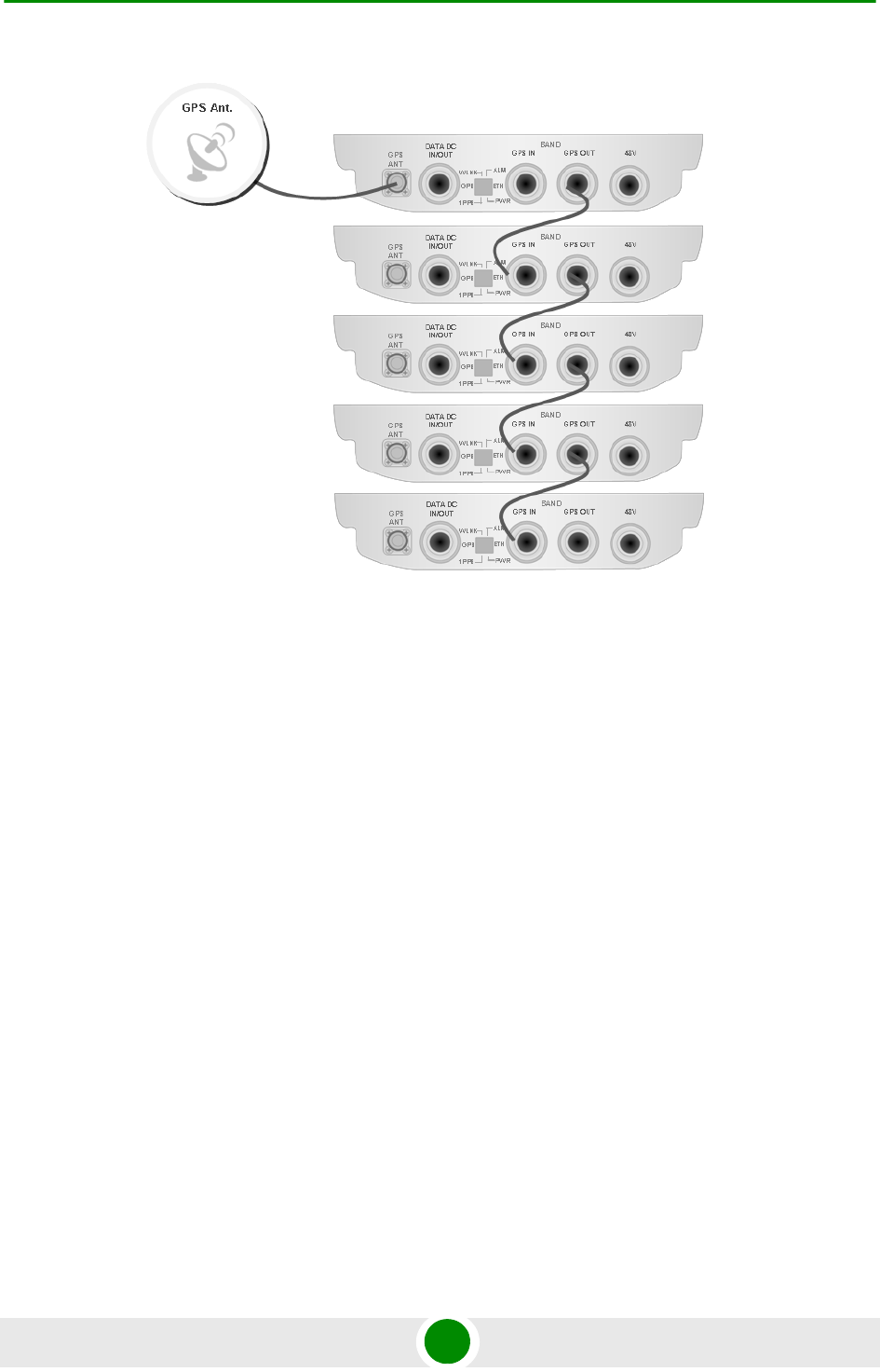
Chapter 2 - Installation GPS Installation
BreezeMAX Extreme 53 System Manual
Figure 2-17: GPS Chaining
Chapter 2 - Installation Indoor Power Supply Installation
BreezeMAX Extreme 54 System Manual
2.4 Indoor Pow er Supply Installat ion
The BTS is powered from a 48V DC power source. Alvarion offers a range of indoor
AC/DC power supplies to support the different power supply methods:
A PoE AC/DC power supply that can supply DC power over the Ethernet to the
BTS via the DATA DC IN/OUT connection. This option is available in the
5 GHz BTS units only (see Section 2.4.1).
Direct 48V DC unit that connects to the 48V connector of the BTS. When
using this power supply option, DC power is available also on the DATA DC
IN/OUT connector, allowing power feeding to a backhauling CPE. (see
Section 2.4.2).
2.4.1 PoE AC/DC Pow e r Supply
A Universal Indoor Unit AC Power Adapter is used to supply DC power over the
Ethernet connection to 5 GHz BTS units. This is an AC to DC power transfer
device, which can provide a 70W single DC output with constant voltage source.
This unit can be wall mounted or placed on the desktop.
For cable connection, refer to “Cable Connection” on page 59
CAUTION
Do not connect two power sources (PoE and DC input) simultaneously.
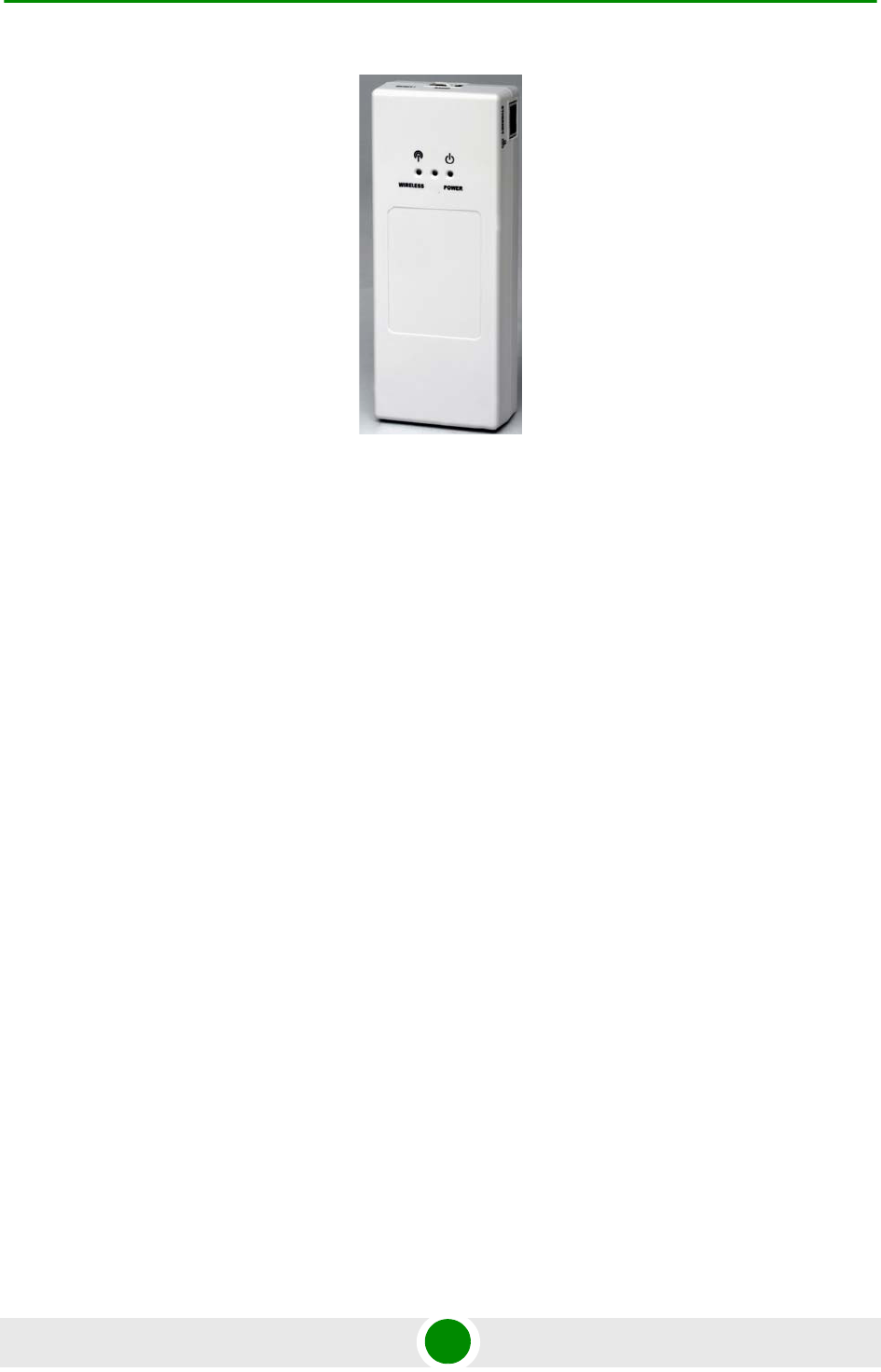
Chapter 2 - Installation Indoor Power Supply Installation
BreezeMAX Extreme 55 System Manual
Figure 2-18: PoE AC/DC Power Supply
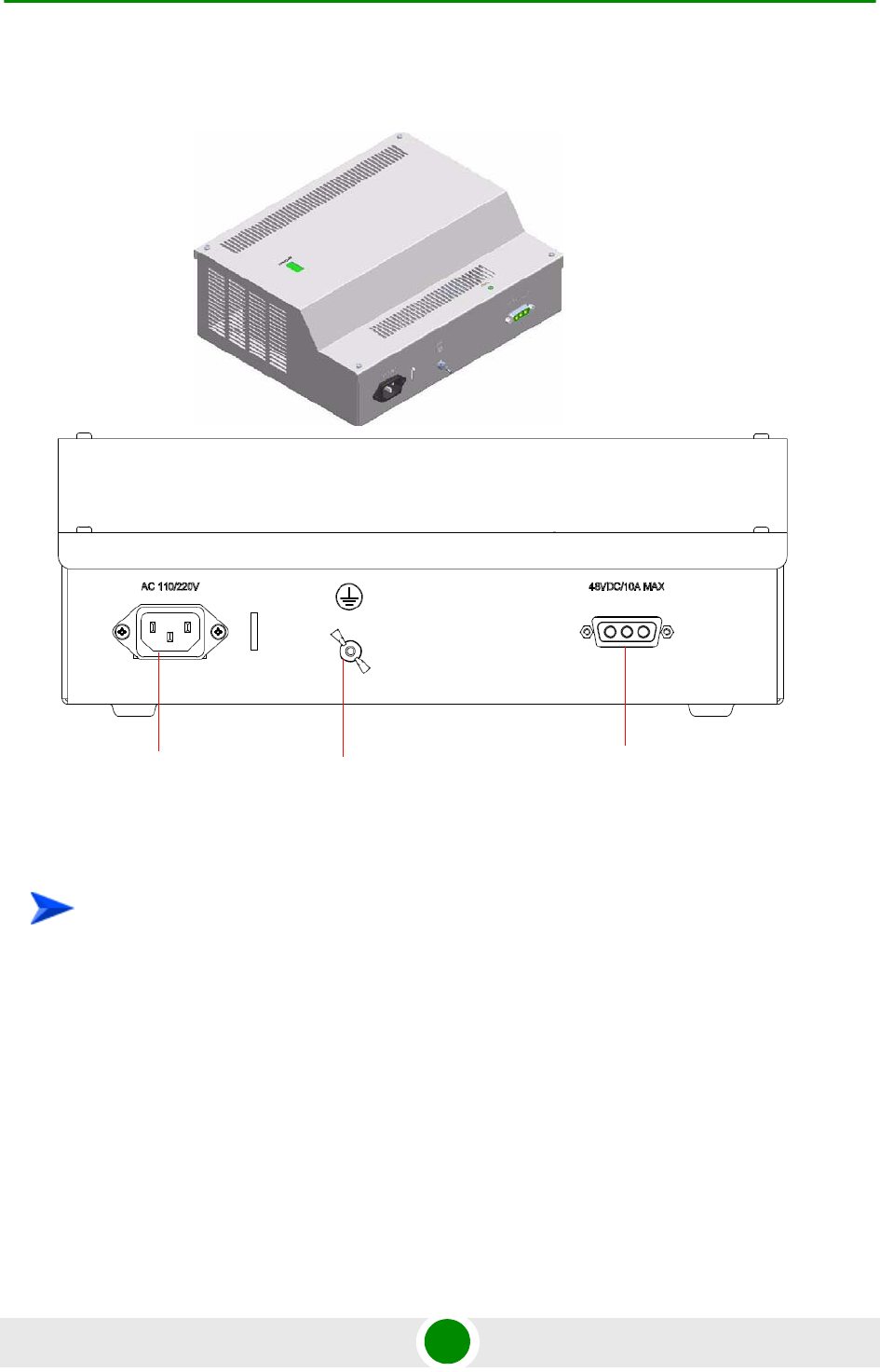
Chapter 2 - Installation Indoor Power Supply Installation
BreezeMAX Extreme 56 System Manual
2.4.2 High Pow e r AC/DC Pow er Supply Unit
1 Place the Power Supply on a table/shelf or use 4 screws to mount the unit to
the wall.
2 For cable connection, refer to “Cable Connection” on page 59.
Figure 2-19: Indoor High Power AC/DC Power Supply Unit
To install the indoor high power supply unit:
DC Power
connection
AC Power
connection
Grounding
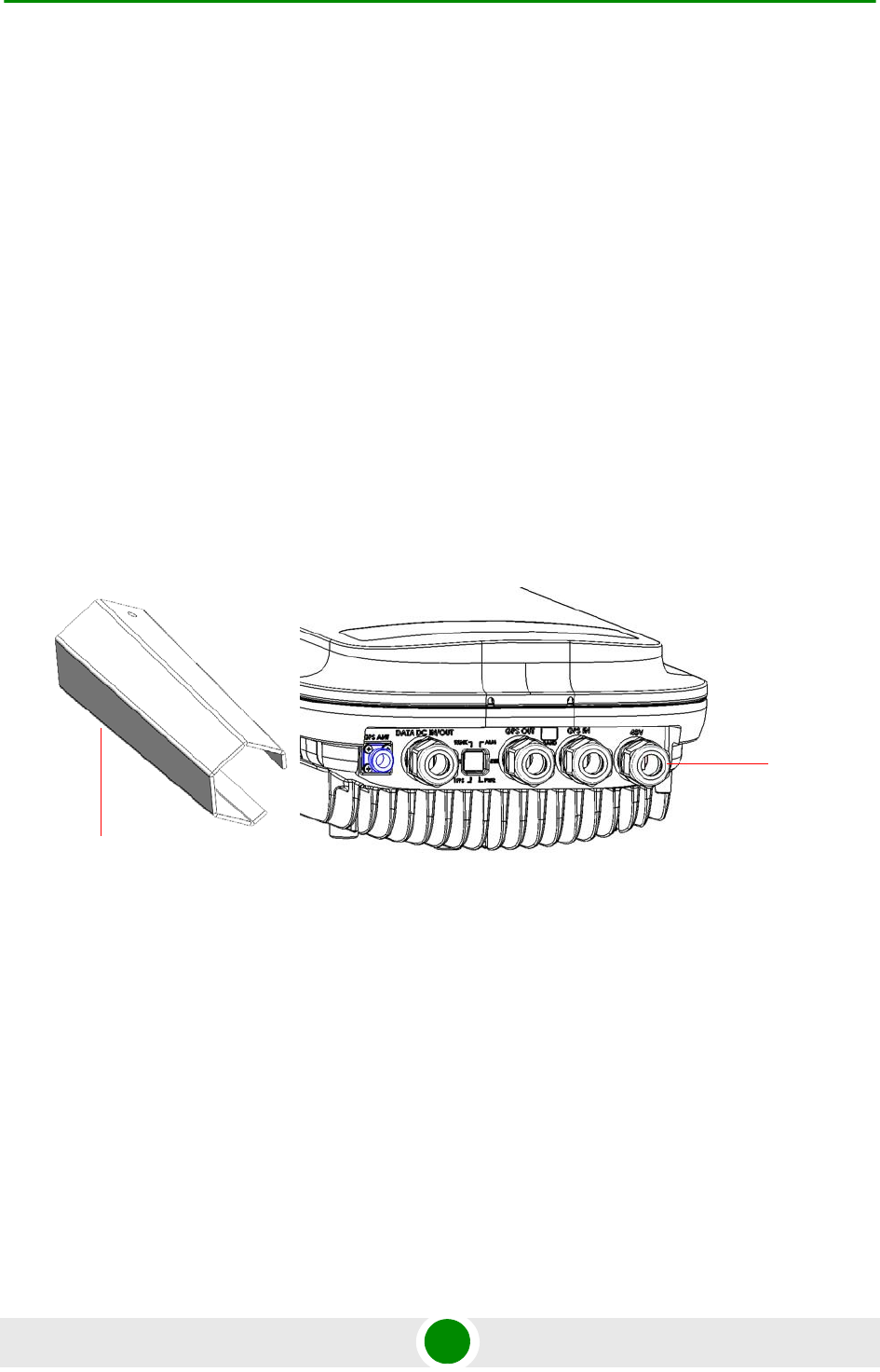
Chapter 2 - Installation Cable Connections
BreezeMAX Extreme 57 System Manual
2.5 Ca ble Connect ions
The BreezeMAX Extreme is provided with sealing glands on all the cable
connectors. The DATA/DC IN/OUT, and GPS IN/OUT cables are to be connected
to the BTS by inserting the cable connector through the sealing gland. The DC
power cable is supplied with a sealing gland that should replace the existing
sealing gland provided with the BTS.
For the GPS ANT connector, a weather-proof metal cap seals the connection. If
this connector is not used, do not remove the metal cap. In case there is only a
rubber cap on this connector, use additional sealing methods to protect this
connection. Use high quality sealing material such as Scotchfil™ Electrical
Insulation Putty from 3M (or equivalent) over-wrapped with either Super 33+ or
Super 88 vinyl Electrical Tape (or equivalent) to ensure IP-67 compliant protection
against dust and water.
A dedicated tool is supplied for fastening the sealing glands (see Figure 2-20).
Figure 2-20: BTS with Sealing Gland and Gland Fastening Tool
Sealing
Gland
Sealing Gland
Fastening Tool
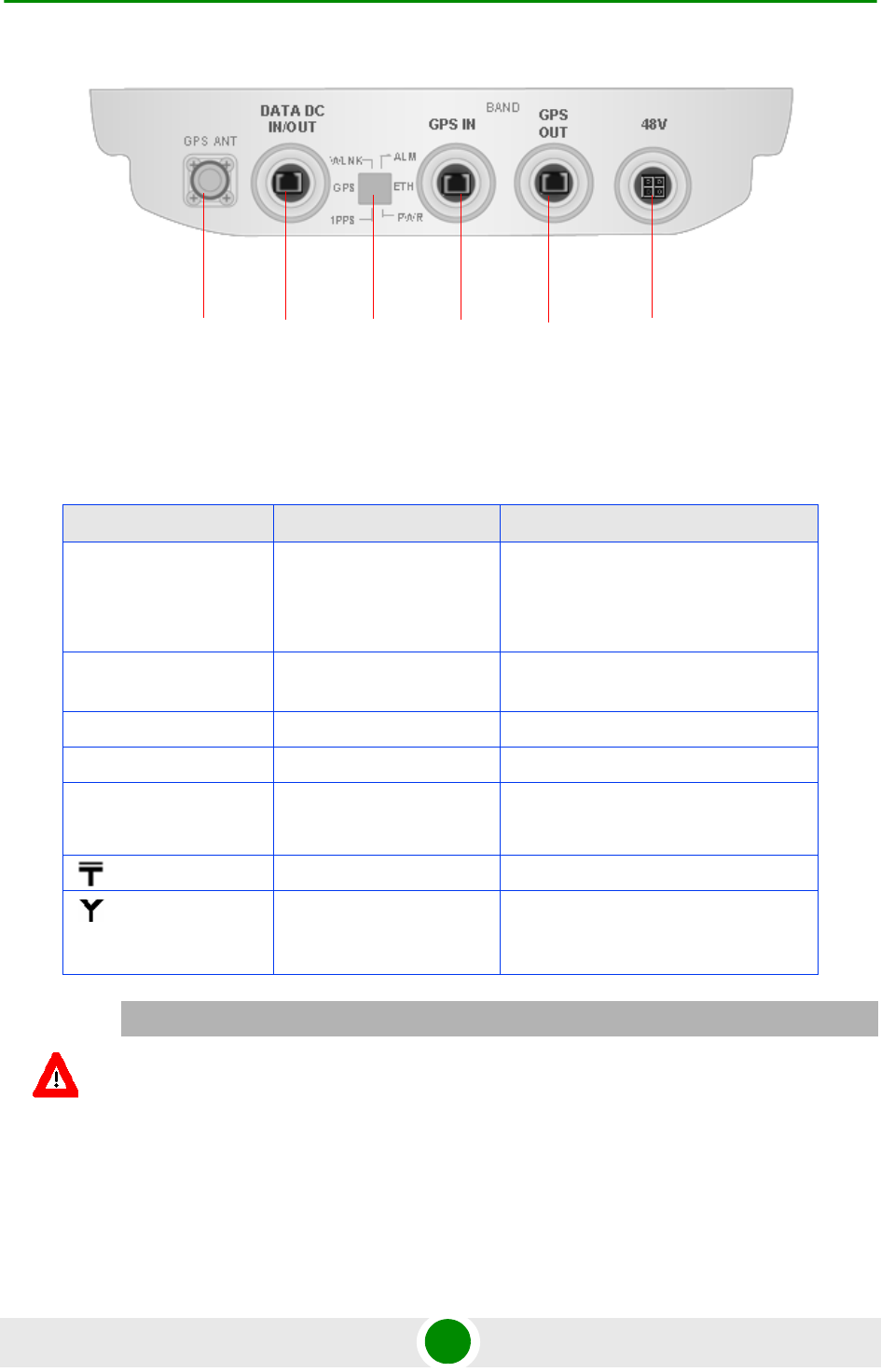
Chapter 2 - Installation Cable Connections
BreezeMAX Extreme 58 System Manual
For LED indication refer to “Operation Verification” on page 69.
Figure 2-21: BTS Connectors (Bottom View)
Table 2-2: BTS Connectors
Connection Connector Type Functionality
DATA DC IN/OUT RJ-45 10/100BASE-T connectivity
Supports MDI/MDIX
PoE In/Out
GPS Antenna TNC jack Connection to GPS antenna (via
lightning arrestor(s))
GPS In RJ-45 GPS signalling from another BTS.
GPS Out RJ-45 GPS signalling to another BTS.
DC source 4-pin Mini Fit High Current
Molex 39-29-1048
DC Power
(GND) Grounding screw Connection to ground (earth)
ANT (1/2) N-Type jack, 50 Ohm Connection to external antenna(s). See
Section 2.6. (Not applicable for
models with integral antenna)
CAUTION
Do not connect two power sources (PoE and DC input) simultaneously.
Sealed LED
window
GPS Antenna GPS OUT
GPS IN
DATA DC
IN/OUT
48V power
Chapter 2 - Installation Cable Connections
BreezeMAX Extreme 59 System Manual
2.5.1 Ca ble Connec tion
2.5.1.1 Grounding Cable Connection
When grounding the unit, use the GND (ground) screw on the unit as a grounding
point. The Grounding screw (marked ) is located on the rear panel of the unit.
1 Connect one end of a grounding cable to the ground terminal and firmly
tighten the grounding screw.
2 Connect the opposite end of the grounding cable to a ground connection.
2.5.1.2 Data/PoE Cable Connection
For all units, use Category 5E Ethernet cables with two shielded RJ-45
connectors from either Alvarion or any of the approved manufacturers, listed in
Table 2-3. The provided cables are crimped.
Consult with Alvarion's specialists on the suitability of other cables.
For 5 GHz units, if you use a PoE indoor power supply (see “Indoor Power Supply
Installation” on page 54), the data port cable is used as a power source cable. In
this case, use a Power over Ethernet (PoE) cable for connecting PoE to the
BreezeMAX Extreme unit.
For 5 GHz units using two radios (diversity) the maximum length of the PoE cable
should not exceed 70m.
To connect the grounding cable:
NOTE
The length of the Data/PoE cable, together with the length of the Ethernet cable should not exceed
100 meters.
CAUTION
As PoE cable conducts power as well, there is a risk of electric shock and energy hazard.
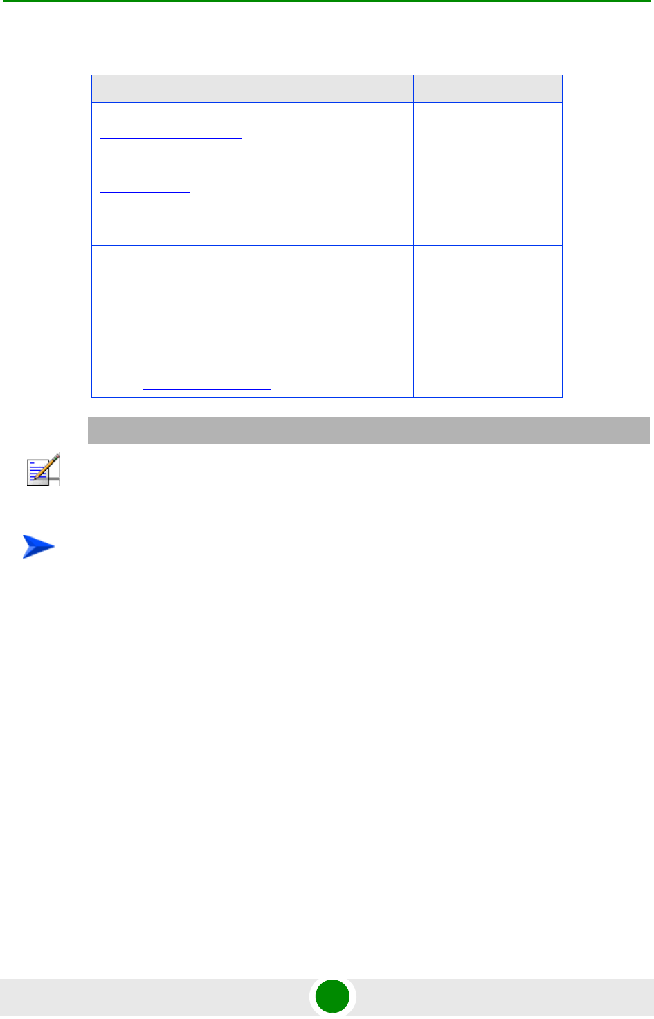
Chapter 2 - Installation Cable Connections
BreezeMAX Extreme 60 System Manual
1 Remove the DATA DC IN/OUT sealing gland from the BTS.
2 Open the gland and thread the cable through the gland's nut.
3 Carefully insert the cable with the already assembled RJ-45 connector
through the gland.
4 Connect the cable to the DATA connection on the BTS.
5 Return the gland. Use the dedicated tool to fasten it.
6 Use the dedicated tool to fasten the sealing gland's nut on the gland body.
Table 2-3: Approved Category 5E Ethernet Cables
Manufacturer Part Number
Superior Cables Ltd.
www.superior-cables.com
612098
HES Cabling Systems
www.hescs.com
H5E-00481
Teldo r
www.teldor.com
8393204101
Southbay Holdings Limited
11th Fl., 15, Lane 347, Jong Jeng Rd.
Shin Juang City, Taipei County
Taiwan, R.O.C.
Attn: Eva Lin
Tel. 886-2-2832 3339
Fax. 886-2-2206 0081
E-mail: eva@south-bay.com.tw
TSM2404A0D
NOTE
In case of missing information (product specifications, ordering information, etc.) regarding these
products on the manufacturer's web site, it is highly recommended to contact the manufacturer's
sales representative directly.
To connect the data cable (with an assembled sealing gland):
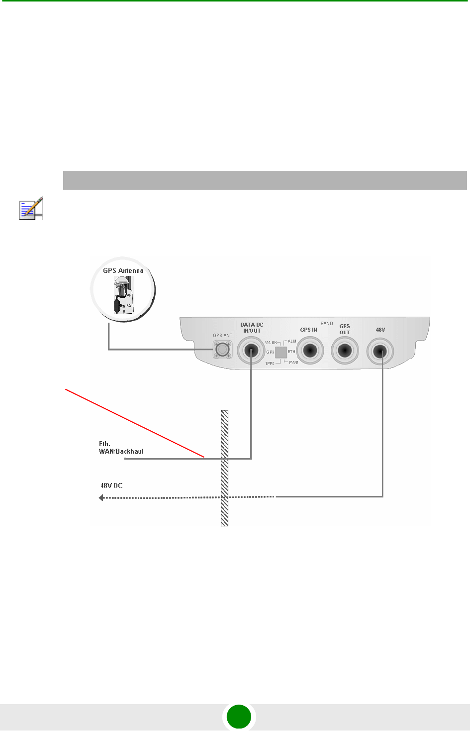
Chapter 2 - Installation Cable Connections
BreezeMAX Extreme 61 System Manual
7 Connect the other end of the data cable to one of the following:
»If you are not using PoE - directly to the backhauling equipment. See
Figure 2-22.
»If you are using PoE (for 5 GHz units only) - to the PoE AC/DC power
supply RJ-45 connector (labeled as Radio). Connect the Ethernet port of
the PoE PS to the backhauling equipment using a standard Ethernet cable.
Connect the PoE PS to the 110/220 VAC mains. See Figure 2-23.
NOTE
The combined lengths of the Ethernet cables should not exceed 100m.
Figure 2-22: Connecting Data Cable Directly to the Backhauling Equipment
Data
cable
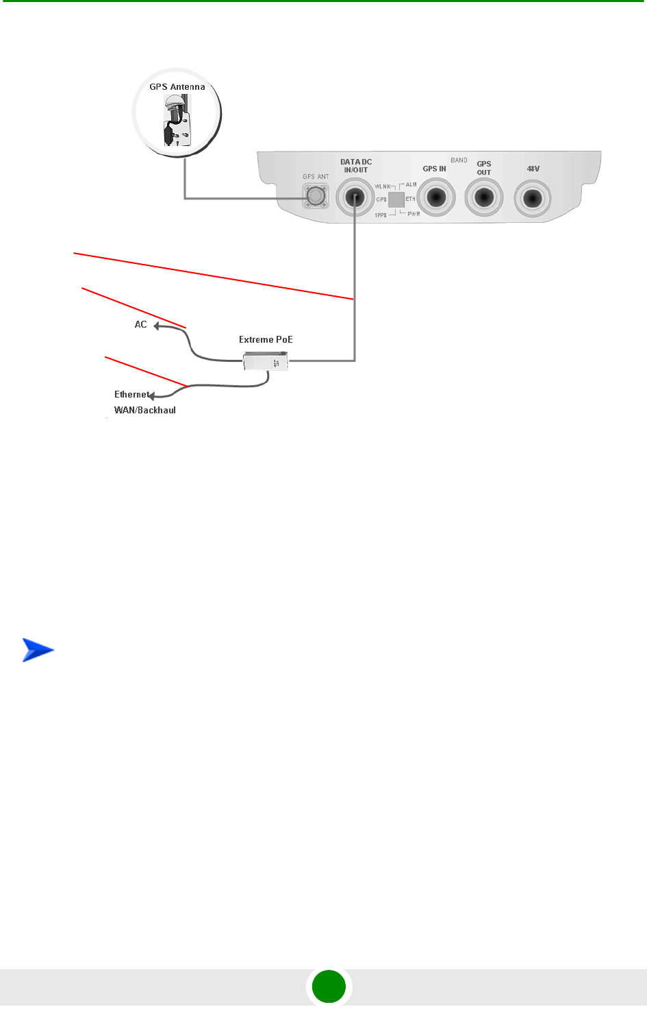
Chapter 2 - Installation Cable Connections
BreezeMAX Extreme 62 System Manual
2.5.1.3 DC Power Cable Connection (not applicable if using PoE)
The power cable is supplied with a specially designed sealing gland that should
replace the existing gland provided with the BreezeMAX Extreme BTS.
Cables are available either open ended at the Power Supply side or with a crimped
D-Type connector.
1 Remove the existing gland from the 48V connection on the BTS.
2 Attach the DC power cable with the already assembled gland to the 48V
connection on the BTS.
3 Separate the sealing gland nut from the gland body.
4 Use the dedicated tool to fasten the gland to the BTS.
5 Use the dedicated tool to fasten the sealing gland's nut on the gland body.
6 Connect the other end of the power cable to the high power AC/DC power
supply.Use a standard power cable to connect to 48V DC power source.
Figure 2-23: Connecting Data Cable When Using PoE (for 5 GHz Units Only)
To connect the power cable:
Data
cable
Ethernet
cable
Power
cable
Chapter 2 - Installation Cable Connections
BreezeMAX Extreme 63 System Manual
Figure 2-24: Connecting Power Cable to the Mains
Power
cable
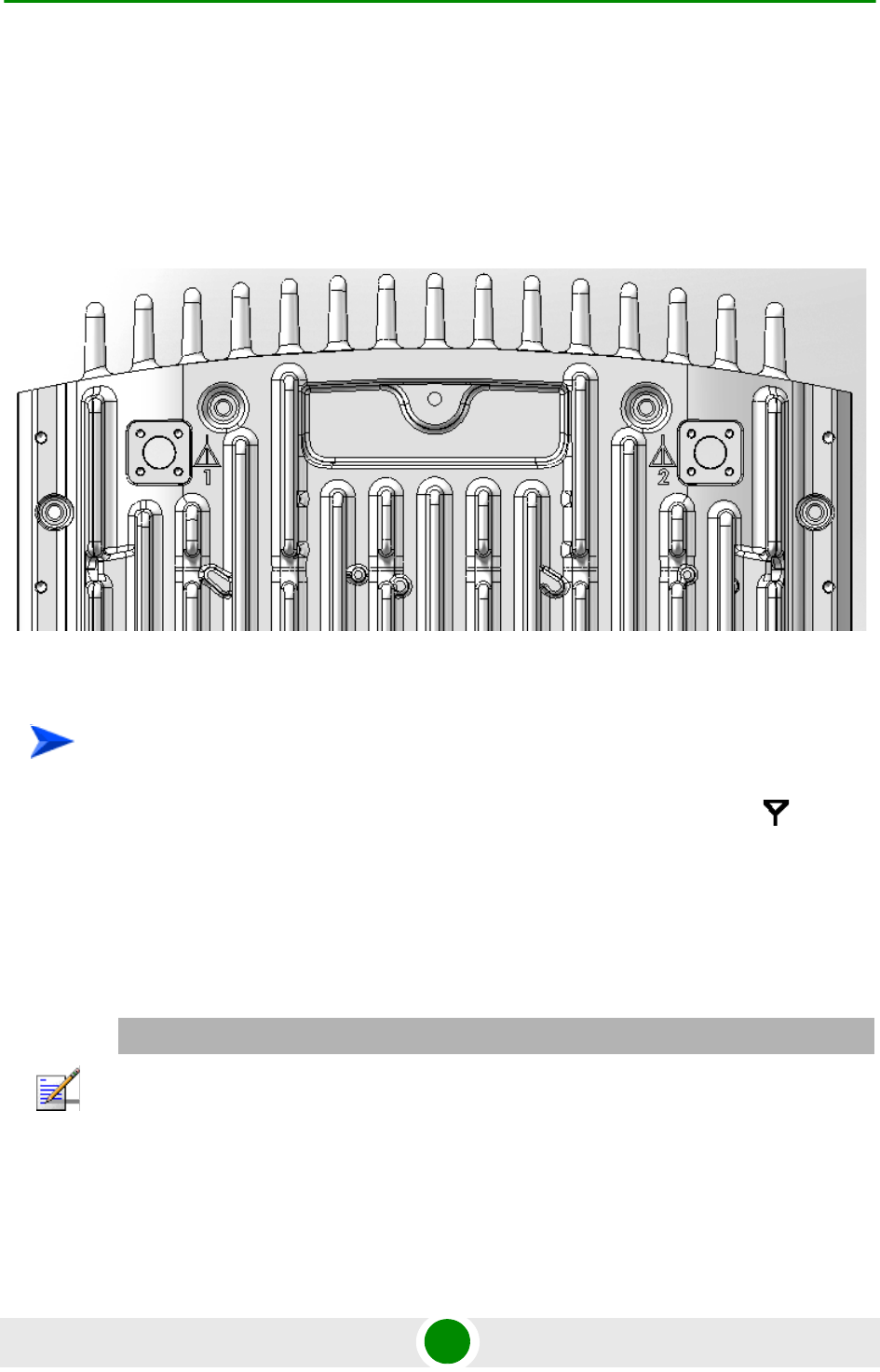
Chapter 2 - Installation External Antennas Connection
BreezeMAX Extreme 64 System Manual
2.6 Ex t erna l Antenna s Connection
Two N-type connectors are used for optional external antenna connection (see
Figure 2-25). The connectors should have an impedance 50Ω and should be
protected against lightning.
1 Connect one end of the coaxial RF cable to the connector (marked ) located
on the rear panel of the unit.
2 Connect the other end of the RF cable to the antenna.
3 The RF connectors should be properly sealed to protect against rain and
moisture.
Figure 2-25: BTS Rear View - External Antenna Connections
To connect the RF cable (units with external antenna):
NOTE
The recommended minimum distance between any two antennas in neighboring sectors is 0.5
meters.
The minimum distance between any two antennas in the same sector (space diversity
configuration) is 10 lambda (λ), where λ=C/Frequency (Hz). C is the speed of light in centimeters
per second which is equal to 29,979,245,800.
The minimum distance between any two antenna in the same sector (space diversity configuration)
is 1.3 meters.

3
Chapter
Commissioning


Chapter 3 - Commissioning Configuring Parameters Required for Remote Management
BreezeMAX Extreme 67 System Manual
3.1 Configuring Pa rame ters Re quired for
Re mote M a nagement
After completing the installation process, as described in the preceding chapter,
some parameters must be configured using either Telnet (the Monitor application)
or AlvariCRAFT. These parameters are necessary to enable remote management of
the BTS.
Refer to Chapter 4 for information on how to access the Monitor application and
how to use it. Refer to the AlvariCRAFT User Manual for information on how to
use it.
The basic parameters are listed in Table 3-1. Refer to Chapter 4 for detailed
information on the applicable parameters.
NOTE
AlvariCRAFT can be used only if the Authorized Managers list in the BTS is either empty (default) or
includes the IP address of the AlvariCRAFT station.
Table 3-1: Basic BTS Parameters
Management Option Parameters
BTS-Connectivity IP address
Subnet Mask
Default Gateway
VLAN ID
VLAN Priority
Authorized Managers
(per manager)
IP Address
Read Community
Write Community
Traps Distribution Enabled

Chapter 3 - Commissioning Configuring Parameters Required for Remote Management
BreezeMAX Extreme 68 System Manual
After the basic parameters have been configured, the BTS can be managed
remotely using either Telnet or SNMP-based management.
NOTE
If no Authorized Manager is defined in the device, it can be managed using SNMP by any station. If
at least one Authorized Manager is defined, the device can be managed only by a station whose
parameters match a defined Authorized Manager. Traps will be sent only to defined Autohorized
Managers (provided traps distribution to the manager is enablesd).

Chapter 3 - Commissioning Operation Verification
BreezeMAX Extreme 69 System Manual
3.2 Operation Verification
To verify the correct operation of the BTS (including the GPS), examine the LED
indicators located on the bottom panel of the unit.
The following tables list the provided LEDs and their associated indications.
Table 3-2: BTS LEDs
Name Description Functionality
PWR Power indication Off - Power failure
Green - Power to ODU is OK, internal 3.3
VDC power supply is OK.
ALM IDU-ODU communication
and synthesizer status
indication
Off -Built-in-test passed successfully.
Red - Critical failure.
ETH Ethernet link status Off - No Ethernet connection
Green - Lights when the backhaul Ethernet is
connected and blinks 500ms on and 500ms
off when data traffic appears on the Ethernet
link.
WLNK Wireless link status Off - No wireless link (no MS is registered)
Green - Blinking when the wireless link is
working (transmitting), indicating that there is
at least one registered MS being served by
the unit.
GPS GPS synchronization status Off - GPS is not synchronized (see below) or
not installed.
Green - On if the GPS is reporting on
reception of at least 4 satellites.
Blinking Green - (0.5 Sec on, 0.5 Sec off) the
number of received satellites decreased from
4 (or more) to 3 or 2 satellites.

Chapter 3 - Commissioning Operation Verification
BreezeMAX Extreme 70 System Manual
* All LEDs are turned on upon power up and turn off after successful completion
of the built-in-test.
1PPS 1PPS clock status Master Unit
Off - GPS is not installed.
Green - 1PPS clock is supplied by GPS.
Slave Unit:
Off - External 1PPS is not supplied.
Blinking Green - blinking at the 1PPS rate
when external 1PPS clock is supplied.
Table 3-2: BTS LEDs
Name Description Functionality

4
Chapter
Operation and Administration

Chapter 4 - Operation and Administration
BreezeMAX Extreme 72 System Manual
In T his Cha pt e r:
“BreezeMAX Extreme System Management” on page 73
“The Monitor Program” on page 74
“IP Addresses Configuration” on page 77
“The Main Menu” on page 78
“BTS Menu” on page 79
“ASN-GW Menu” on page 118
“Sector Menu” on page 158
“BS Menu” on page 178
“Radio Channel Menu” on page 200
“Antenna Menu” on page 202
“GPS Menu” on page 205
“MS Menu” on page 212
“Parameters Summary” on page 217

Chapter 4 - Operation and Administration BreezeMAX Extreme System Management
BreezeMAX Extreme 73 System Manual
4.1 BreezeM AX Extreme System
Mana ge ment
BreezeMAX Extreme can be managed using any of the following options:
SNMP based management using AlvariSTAR/AlvariCRAFT (or another network
management system customized to support management of BreezeMAX
Extreme).
Using Telnet to access the embedded Monitor application via the Ethernet
port.
This chapter describes how to manage the system using the Monitor application.
For information on managing the system using AlvariSTAR/AlvariCRAFT refer to
the applicable documentation.
NOTE
It is not possible to manage the BreezeMAX Extreme Base Transceiver Station via the wireless link
(from the MS’s side).
Chapter 4 - Operation and Administration The Monitor Program
BreezeMAX Extreme 74 System Manual
4.2 T he Monit or Program
4.2.1 Accessing t he Monit or Progra m
1The PC used for accessing the Monitor program should be configured
according to the BTS Management Connectivity parameters (see “Connectivity”
on page 88).
2Run the Telnet program connecting to the IP address of the connected port.
3Select the access level according to your access rights.
4The Enter the password message is displayed. Enter the password and press
the Enter key to get to the Main menu. The default passwords are:
4.2.2 Using the M onit or Program
This section describes the Monitor program structure and navigation rules.
To access the Monitor program using Telnet:
Table 4-1: Default Passwords
Access Level Default Password
Administrator admin
Installer installer
Monitor monitor
NOTE
Following three unsuccessful login attempts (using incorrect passwords), access to the monitor
program will be blocked for approximately 10 minutes.
If you forgot the Installer or Monitor password, the Administrator can login (with the Administrator
password) and define a new password for Installer and/or Monitor access level.
If you forgot the Administrator password, type "help" to receive a challenge string consisting of 24
characters. Contact Alvarion's Customer Service and provide the challenge string (after user
identification) to receive a temporary password. You can use this password only once to enter the
program. The password must be changed during the session to a different "permanent" password.
The system administrator should be notified of this new password. Five consecutive errors in
entering the temporary password will invalidate it. In this case, repeat this procedure to receive a
new challenge string for a new temporary password.

Chapter 4 - Operation and Administration The Monitor Program
BreezeMAX Extreme 75 System Manual
There are three access levels to the Monitor program. The available actions
depend on the access level (password) used for accessing the program:
»Administrator: Read/Write permissions for all parameters. The default
password is admin.
»Installer: Read/Write permissions for all options excluding the Change
Password option. The default password is installer.
»Monitor: Read-only permissions for all parameters. The default password
is monitor.
Each menu or submenu specifies the unit type (BreezeMAX Extreme/BTS), the
Management IP address, the running SW version and a description of the
menu.
Each menu or submenu displays a list of numbered options. To access an
option, enter the number of the required option at the > prompt.
At any point in the program, you can use the Esc key to return to the previous
menu (one level up) without applying any change.
The first selectable item in most menus is the Show option, enabling to view
the current configuration of the applicable parameters. For some menus some
additional status information is displayed.
For certain parameters, an updated value is applied only after reset or after
entering a specific command. For these parameters, both Configured and
Current values are displayed in relevant Show menus.
The Update/Add options will display all applicable parameters line by line,
allowing to conveniently edit all of them. The availability and/or value range of
certain parameters may change according to the value selected for a previous
parameter belonging to the same group. The current value is displayed for
each parameter. To keep the current value - press Enter. To change it - enter a
new value and press Enter. The new/modified configuration will take effect
only after completing the configuration process for the all relevant parameters.
Press the Tab key for context sensitive help text (where applicable).
If an erroneous value was entered - the reason of the error or help text will be
displayed, and the parameter entry text will be displayed again.

Chapter 4 - Operation and Administration The Monitor Program
BreezeMAX Extreme 76 System Manual
Many menus include a Select By option, enabling to get a sub-menu for a
selected entity according to the selection criteria.
If the Monitor program is not used for the period of time defined by the Monitor
Inactivity Time-out (see “Monitor Inactivity Timeout” on page 109), the session
will be terminated automatically.
Select the Exit option in the Main menu to exit the program and terminate the
session.

Chapter 4 - Operation and Administration IP Addresses Configuration
BreezeMAX Extreme 77 System Manual
4.3 IP Addresses Configurat ion
4.3.1 IP Addre ss Configurat ion Re st ric tions
1The following IP addresses should not be used and will be rejected:
0.0.0.0
224.0.0.0 - 255.255.255.255 (Multicasts, RFC 3171 D, RFC 1700 E)
4.3.2 IP Subnet s
In a binary representation (32 bits) a Subnet Mask string must comprise a series
of contiguous binary '1's starting from the MSB, followed by a series of contiguous
binary '0's.
Subnet Masks 0.0.0.0 (all zeros, meaning “nothing”) and 255.255.255.255 (all
ones, meaning “this address only”) are illegal and will be rejected.

Chapter 4 - Operation and Administration The Main Menu
BreezeMAX Extreme 78 System Manual
4.4 T he Main M enu
The Main menu of the Monitor program includes the following options:
1 - BTS (see “BTS Menu” on page 79)
2 - ASN-GW (see “ASN-GW Menu” on page 118)
3 - Sector (see “Sector Menu” on page 158)
4 - BS (see “BS Menu” on page 178)
5 - Radio Channel (see “Radio Channel Menu” on page 200)
6 - Antenna (see “Antenna Menu” on page 202)
7 - GPS (see “GPS Menu” on page 205)
8 - MS (see “MS Menu” on page 212)
X - Exit (select to exit the Monitor program and terminate the Telnet session)

Chapter 4 - Operation and Administration BTS Menu
BreezeMAX Extreme 79 System Manual
4.5 BT S Menu
The BTS menu includes the following options:
Show Summary
Show Properties
Show License Properties
Configuration
Unit Control
Fault Management
Performance Counters
4.5.1 Show Sum mar y
Select this option to view the current and (where applicable) configured values of
all configurable BTS parameters and options:
General:
BTS Number
BTS Name
BTS Location
BTS Contact
For details on General BTS parameters refer to “General Parameters” on page 86.
BTS Working Mode:
Current BTS Working Mode
Configured BTS Working Mode

Chapter 4 - Operation and Administration BTS Menu
BreezeMAX Extreme 80 System Manual
For details on BTS Working Mode parameter refer to “BTS Working Mode” on
page 87.
Management Connectivity:
Current IP Address
Configured IP Address
Current Subnet mask
Configured Subnet mask
Current Default Gateway
Configured Default Gateway
Current VLAN ID
Configured VLAN ID
Current VLAN Priority*
Configured VLAN Priority*
* VLAN Priority values (Current and/or Configured) are available only if the
corresponding VLAN ID is other than Untagged.
For details on Management Connectivity parameters refer to “Connectivity” on
page 88.
Ethernet Interface
Speed and Duplex After Negotiation (Mbps)
The BTS operates in Auto Negotiation mode. This parameter shows the speed and
duplex mode of the Ethernet port after auto-negotiation has been completed.
Authorized Managers (for each defined manager):
Authorized Managers Index
Manager IP Address
Read Community

Chapter 4 - Operation and Administration BTS Menu
BreezeMAX Extreme 81 System Manual
Write Community
Trap Distribution Enabled
For details on Authorized Managers refer to “Authorized Managers” on page 89.
General Radio:
Current Operator ID
Configured Operator ID
Operator Name
Current Service Zone ID
Configured Service Zone ID
Service Zone Name
For details on General Radio parameters refer to “Radio” on page 91.
Unit Operation Mode:
Current Operation Mode
Configured Operation Mode
For details on Operation Mode parameter refer to “Operation Mode” on page 94.
Country Code:
Current Country Code
Configured Country Code
For details on Country Code parameter refer to “Country Code” on page 99.
ATPC Mode:
ATPC Mode: Open Loop. It is assumed that Open Loop Transmit Power Control
is used by the MSs, meaning that each MS calculates the link loss considering
the BS Tx power and preamble RSSI and determines its Tx power taking into

Chapter 4 - Operation and Administration BTS Menu
BreezeMAX Extreme 82 System Manual
account the estimated link loss, the number of sub-channels used and the
SNR required for the relevant rate.
DL/UL Ratio:
Current DL / UL Ratio
Configured UDL / UL Ratio
For details on DL/UL Ratio parameter refer to “DL / UL Ratio” on page 101.
DFS / DCS
Current Random Channels Selection
Configured Random Channels Selection
DFS Type (per sector)
Current DFS Frequency Management Level
Configured DFS Frequency Management Level
DFS/DCS parameters are applicable only for 5 GHz units. DFS parameters are
applicable only if the current Country Code supports DFS. For details on DFS and
DCS parameters refer to “DFS/DCS” on page 101.
4.5.2 Show Propertie s
Select this option to view the general hardware and software properties of the
device:
Product Type (BMAX-Extreme)
Operational SW File Name
Operational SW Version
Shadow SW File Name
Shadow SW Version
Running From (Operational or Shadow)

Chapter 4 - Operation and Administration BTS Menu
BreezeMAX Extreme 83 System Manual
Operational Boot SW Version
Frequency File Name
Frequency File Version
Digital Board Assembly Version
Digital Board HW Version
Radio 1: The frequency band supported by the radio
Radio 1 HW version
Radio 1 HPA Version
Radio 2 (if exists): The frequency band supported by the radio
Radio 2 HW version
Radio 2 HPA Version
Serial Number
Cumulative Power On Time (minutes): The cumulative power-on time of the
device since first power-up.
Cumulative Life Time (minutes): The cumulative life time of the device since
first power-up.
Measured Temperature (degrees Celsius)
Product HW Type: A string defining the HW configuration of the device.
FPGA Version
BTS MAC Address
Country Code

Chapter 4 - Operation and Administration BTS Menu
BreezeMAX Extreme 84 System Manual
4.5.3 Show Lic ense Propert ies
Select this option to view the properties of the current license or the properties of
the primary license file and secondary license files previously loaded to the device
(if applicable).
Starting in release 1.5, each unit is shipped with a primary license file that
includes the following:
Basic hardware dependent capabilities that cannot be modified:
»Operational Modes: The Operational Mode(s) that can be supported.
»Antenna Type: Internal or External
»Antenna Gain (dBi): The gain of the antenna. In the current release the
gain of the internal antenna is 14 dBi. Not applicable for an external
antenna.
»Antenna Beam Width (degrees): The beam width in degrees of the
antenna. In the current release the beam width of the internal antenna is
90 degrees. Not applicable for an external antenna.
»Antenna Polarization: The polarization of the antenna. In the current
release the polarization of the internal antenna is Dual Slant (including
units where only one single slant antenna is used). Not applicable for an
external antenna.
NOTE
For a 1SIS unit the basic operation mode is Single Sector Single BS no Diversity. The Single Sector
Dual BS no Diversity operation mode is applicable only if 20 MHz bandwidth (see below) is
supported.
For a 1DIV unit the basic operation mode is Single Sector Single BS with Diversity. The Single
Sector Dual BS with Diversity operation mode is applicable only if 20 MHz bandwidth (see below) is
supported.

Chapter 4 - Operation and Administration BTS Menu
BreezeMAX Extreme 85 System Manual
Modifiable features and capabilities:
»Enable MIMO B: Indicates whether operation using MIMO B (or MIMO
A/B) is supported (supported by default for 1DIV units).
»Maximum Number of MSs: The maximum number of MSs that can be
served simultaneously by the unit.
»Internal ASN-Gateway: Indicates whether the internal ASN-GW is
supported (supported by default for all units).
»External ASN-GW: Indicates whether operation with an external ASN-GW
over R6 is supported.
»Video: Indicates whether Optimized Video service is supported (for future
use when Optimized Video service will be available).
»20 MHz: Indicates whether operation with a 14 MHz (3.65 GHz units only)
or 20 MHz bandwidth is supported (20 MHz support availability depends
also on the specific unit’s hardware. This feature is not applicable for 2SIS
units).
License files with support for additional capabilities can be loaded to the device
using TFTP. For details on loading license files refer to “Download License File To
Unit” on page 109 or to the relevant AlvariSTAR/AlvariCRAFT User Manual. Each
secondary license file can include licenses for any number of the modifiable
features. The licensing feature is additive (once support for a certain capability is
enabled it cannot be disabled). A license file is prepared for a specific unit using
unique identifiers (MAC address and Serial Number) and can be loaded
successfully only to this unit.
The Show License Properties menu include the following options:
Show License Summary
Show License Files
4.5.3.1 Show License Summary
Select this option to view the current licenses status. The displayed information
includes the basic hardware dependent features and the current status of all
modifiable features, taking into account all the license files loaded to the unit (if
applicable). In addition, the Number of Connected MSs is shown next to the
Maximum Number of MSs entry. This is the current number of MSs served by

Chapter 4 - Operation and Administration BTS Menu
BreezeMAX Extreme 86 System Manual
the unit, and the information is provided to enable the administrator to decide
whether additional MSs can be served with the current license capabilities.
4.5.3.2 Show License Files
Select this features to view the license files history. The display includes the
content of the primary license file loaded during production, followed by the
details of additional secondary license files loaded to the device (if applicable)
according to the order of activation. In addition to the license of relevant
capabilities, identification details of each file (file name and catalog name) are also
provided.
4.5.4 Configurat ion
The Configuration menu includes the following options:
General Parameters
BTS Working Mode
Connectivity
Authorized Managers
Radio
4.5.4.1 General Parameters
The BTS General Parameters submenu enables viewing the current values and
updating the general BTS parameters. The General Parameters include the
following:
BTS Number
BTS Name
BTS Location
BTS Contact
4.5.4.1.1 BTS Number
A BTS identifier for management purposes. Should be unique in the managed
network.

Chapter 4 - Operation and Administration BTS Menu
BreezeMAX Extreme 87 System Manual
The range is from 1 to 999999.
The default is 0. A different number (unique in the managed network) must be
configured.
4.5.4.1.2 BTS Name
An optional descriptive parameter. A string of up to 32 printable characters.
The default is null (an empty string).
4.5.4.1.3 BTS Location
An optional descriptive parameter. A string of up to 64 printable characters.
The default is null (an empty string).
4.5.4.1.4 BTS Contact
An optional descriptive parameter. A string of up to 64 printable characters.
The default is null (an empty string).
4.5.4.2 BTS Working Mode
The BTS Working Mode defines the network ASN-GW architecture and the method
of MS authentication and service provisioning for embedded ASN-GW.
The available options are:
Embedded Distributed ASN-GW Centralized Authentication: The ASN-GW
functionality resides in the BTS (distributed architecture). MS authentication
and services provisioning are managed by a AAA server: MSs (see “MS Menu”
on page 212) cannot be added or deleted, and MS Services (see “MSs Services”
on page 129) are not configurable locally (read-only).
Embedded Distributed ASN-GW Local Authentication: The ASN-GW
functionality resides in the BTS (distributed architecture). MS authentication
and services provisioning are managed by the ASN-GW using local
configuration. The AAA menu (see “AAA” on page 118) is not applicable.
External ASN-GW: The ASN-GW is a separate entity (centralized architecture)
that communicates with the BTS over R6 interface. MS authentication and
services provisioning are managed by a AAA server. MSs (see “MS Menu” on
page 212) cannot be added or deleted. All Services configuration (see “Services
Menu” on page 128) are managed by the external ASN-GW and are not
available to the user. The AAA menu (see “AAA” on page 118) is not applicable.

Chapter 4 - Operation and Administration BTS Menu
BreezeMAX Extreme 88 System Manual
When changing the BTS Working Mode from Embedded Distributed ASN-GW
Local Authentication to another mode where provisioning is managed by a AAA
server, and vice versa, MSs and MS-Services tables records are erased and all
connections are deleted.
When changing the BTS Working Mode from any Embedded Distributed ASN-GW
mode to External ASN-GW mode all Services tables (see “Services Menu” on
page 128) and AAA servers (see “AAA” on page 118) are erased.
The default BTS Working Mode is Embedded Distributed ASN-GW Centralized
Authentication.
4.5.4.3 Connectivity
The Connectivity parameters enable viewing the current and configured values
and updating the parameters of the management interface. The Connectivity
parameters include the following:
IP Address
Subnet mask
Default Gateway
VLAN ID
VLAN Priority
4.5.4.3.1 IP Address
The IP address of the Management interface.
The default is 1.1.1.23.
Refer to the limitations described in “IP Addresses Configuration” on page 77.
4.5.4.3.2 Subnet mask
The Subnet Mask of the Management interface.
The default is 255.255.255.0.
Refer to the limitations described in “IP Addresses Configuration” on page 77.
4.5.4.3.3 Default Gateway
The Gateway IP address of the Management interface.
The default is 0.0.0.0 (meaning no default gateway).
Chapter 4 - Operation and Administration BTS Menu
BreezeMAX Extreme 89 System Manual
The Default Gateway must be in the subnet of the IP Address. Refer to the
limitations described in “IP Addresses Configuration” on page 77.
4.5.4.3.4 VLAN ID
The VLAN ID to be used with management messages.
Available values are from 1 to 4094, or 4096 for No VLAN (untagged).
The default is 4096 (No VLAN).
4.5.4.3.5 VLAN Priority
The Management VLAN Priority value. Applicable only if VLAN ID is other than
4096 (No VLAN).
Available values are from 0 to 7. The default is No VLAN Priority.
4.5.4.4 Authorized Managers
The Authorized Managers submenu enables defining the properties of
management stations that are allowed to manage the BTS using SNMP.
The Authorized Manager submenu includes the following options:
Show Summary
Select
Add
4.5.4.4.1 Show Summary
Select this option to view the details of all currently defined authorized managers.
4.5.4.4.2 Select
This option enables selecting an existing authorized manager for viewing or
updating its properties or for deleting it from the database. The selection is based
on the authorized manager's IP address.
The Selected Manager submenu includes the following options:
Show: For viewing the details of the selected Manager.
NOTE
If no Authorized Manager is defined in the device, it can be managed using SNMP by any station,
with the default Read (public) and Write (private) Communities. If at least one Authorized Manager
is defined, the device can be managed only by a station whose parameters match a defined
Authorized Manager.

Chapter 4 - Operation and Administration BTS Menu
BreezeMAX Extreme 90 System Manual
Update: For updating the properties of the selected Manager, except to its IP
Address. Refer to the following Add section for details on the configurable
parameters.
Delete: For deleting the selected Manager from the database.
4.5.4.4.3 Add
Select this option to add a new authorized manager. Up to 5 Authorized Managers
can be defined. The following parameters can be configured:
Manager IP Address
Read Community
Write Community
Traps Distribution Enabled
4.5.4.4.3.1 Manager IP Address
The IP address of the Authorized Manager. Refer to the limitations described in “IP
Addresses Configuration” on page 77.
The IP Address of an existing Manager cannot be updated (to change it you must
first delete the Manager).
4.5.4.4.3.2 Read Community
The SNMP Read Community to be used by the Authorized Manager.
Valid Community strings: 1 to 32 printable characters, case sensitive.
The default is public.
4.5.4.4.3.3 Write Community
The SNMP Write Community to be used by the Authorized Manager.
Valid Community strings: 1 to 32 printable characters, case sensitive.
The default is private.
4.5.4.4.3.4 Traps Distribution Enabled
The Traps Distribution Enabled parameters whether to enable or disable sending
of traps to the Authorized Manager.
The default is Enable.

Chapter 4 - Operation and Administration BTS Menu
BreezeMAX Extreme 91 System Manual
4.5.4.5 Radio
The Radio submenu includes two options:
Show: Enables viewing the current values of the Radio parameters. For
parameters that are applied only after reset, the configured values are also
displayed:
»General Radio
◊Current Operator ID
◊Configured Operator ID
◊Operator Name
◊Current Service Zone ID
◊Configured Service Zone ID
◊Service Zone Name
»Unit Operation Mode
◊Current Operation Mode
◊Configured Operation Mode
»Country Code
◊Current Country Code
◊Configured Country Code
»ATPC Mode
◊ATPC Mode: Open Loop. It is assumed that Open Loop Transmit Power
Control is used by the MSs, meaning that each MS calculates the link
loss considering the BS Tx power and preamble RSSI and determines

Chapter 4 - Operation and Administration BTS Menu
BreezeMAX Extreme 92 System Manual
its Tx power taking into account the estimated link loss, the number of
sub-channels used and the SNR required for the relevant rate.
»UL / DL Ratio
◊Current UL / DL Ratio
◊Configured UL / DL Ratio
»DFS/DCS (if applicable)
◊Current Random Channels Selection
◊Configured Random Channels Selection
◊DFS Type, per Sector: FCC or ETSI, applicable only if DFS is supported
by the current Country Code.
◊Current DFS Frequencies Management Level
◊Configured DFS Frequencies Management Level
Update: Enables updating the configured values of Radio parameters.
The configurable Radio Parameters include the following:
Operator ID
Operator Name
Service Zone ID
Service Zone Name
Operation Mode
Country Code
DL / UL Ratio
DFS/DCS (applicable only for 5 GHz units)
4.5.4.5.1 Operator ID
The Operator ID is a unique identifier of the radio network. The same Operator ID
must be used by all devices belonging to the same wireless access network.

Chapter 4 - Operation and Administration BTS Menu
BreezeMAX Extreme 93 System Manual
The Operator ID is presented as x.y.z, where x, y, z are in the range 0 to 255.
The default Operator ID is 0.0.0.
The BTS will not start transmitting until a different Operator ID is defined.
4.5.4.5.2 Operator Name
An optional descriptive parameter. A string of up to 32 printable characters.
The default is null (an empty string).
4.5.4.5.3 Service Zone ID
The Service Zone ID form a part of the BS ID (see BS ID in Section 4.8.1). Each
Service Zone may include up to a total of 32 cells, with a maximum of 18 cells
with 4 sectors per cell.
The value range is from 0 to 2047.
The default value 0.
The BTS will not start transmitting until a different Service Zone ID is defined.
4.5.4.5.4 Service Zone Name
An optional descriptive parameter. A string of up to 32 printable characters.
The default is null (an empty string).
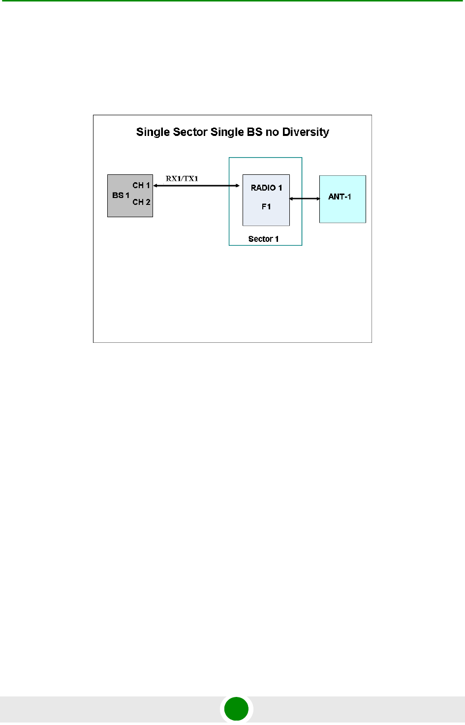
Chapter 4 - Operation and Administration BTS Menu
BreezeMAX Extreme 94 System Manual
4.5.4.5.5 Operation Mode
The following operation modes are supported in current release:
Single Sector Single BS no Diversity
:
The Single Sector Single BS no Diversity operation mode is applicable only for
1SIS model units. A single Radio Channel of a single BS connected to a single
internal radio provides a bandwidth of 5, 7 (applicable only for 3.65 GHz units), or
10 MHz per sector.
Only SISO (no diversity) Diversity Mode can be supported by units operating in
this mode.
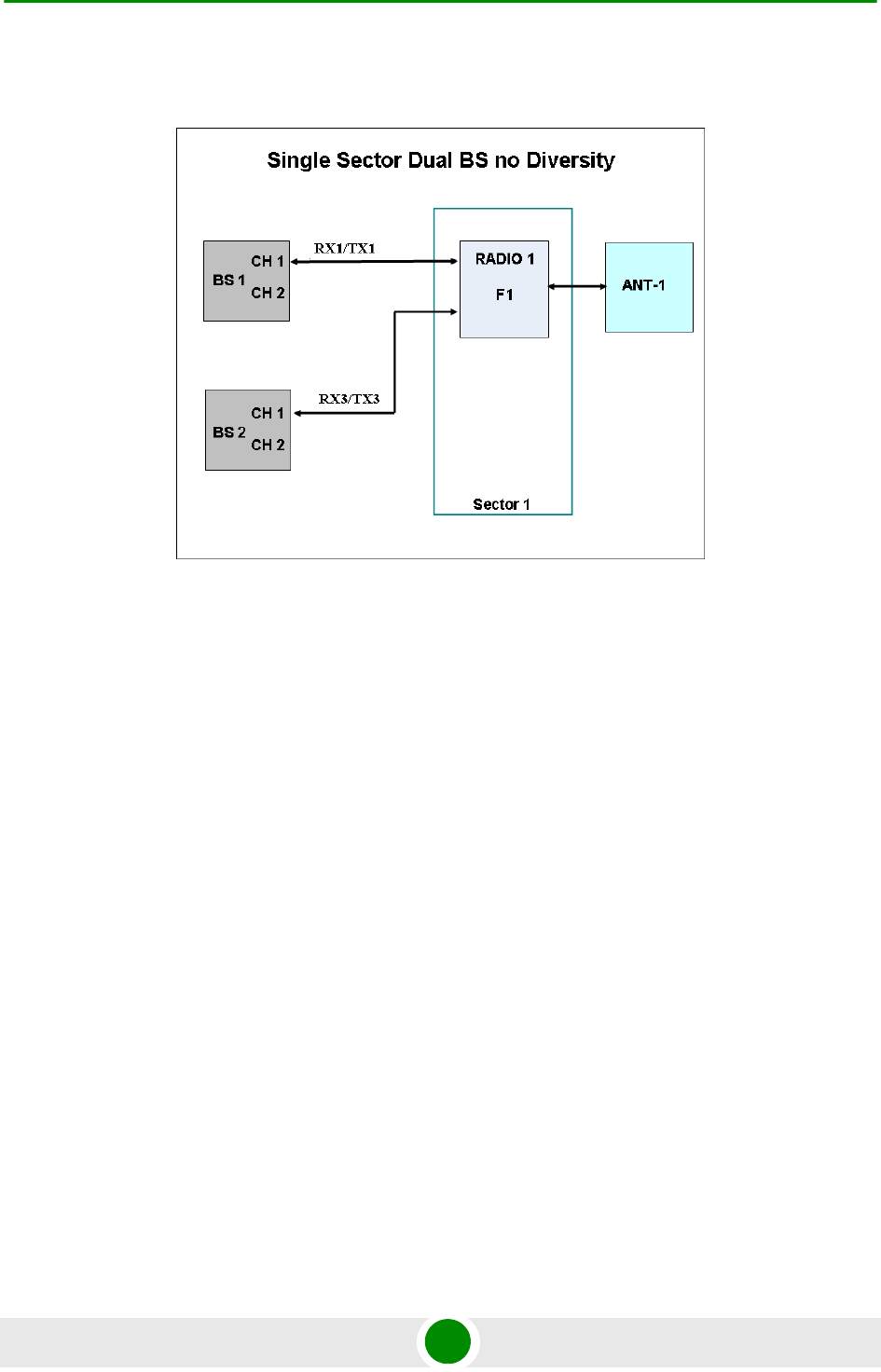
Chapter 4 - Operation and Administration BTS Menu
BreezeMAX Extreme 95 System Manual
Single Sector Dual BS no Diversity
The Single Sector Dual BS no Diversity operation mode is applicable only for 1SIS
model units with a license for 20 MHz bandwidth. Two BSs connected to a single
internal radio with one Radio Channel per each BS provide a total bandwidth of
14 (applicable only for 3.65 GHz units) or 20 MHz per sector.
Only SISO (no diversity) Diversity Mode can be supported by units operating in
this mode.
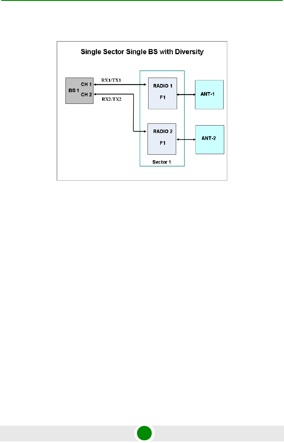
Chapter 4 - Operation and Administration BTS Menu
BreezeMAX Extreme 96 System Manual
Single Sector Single BS with Diversity:
The Single Sector Single BS with Diversity operation mode is applicable only for
1DIV model units. The two Radio Channels of a single BS connected to two
internal radios provide a bandwidth of 5, 7 (applicable only for 3.65 GHz units), or
10 MHz per sector.
Units operating in this mode can use either MIMO Matrix A or MIMO Matrix A&B
Diversity Mode.
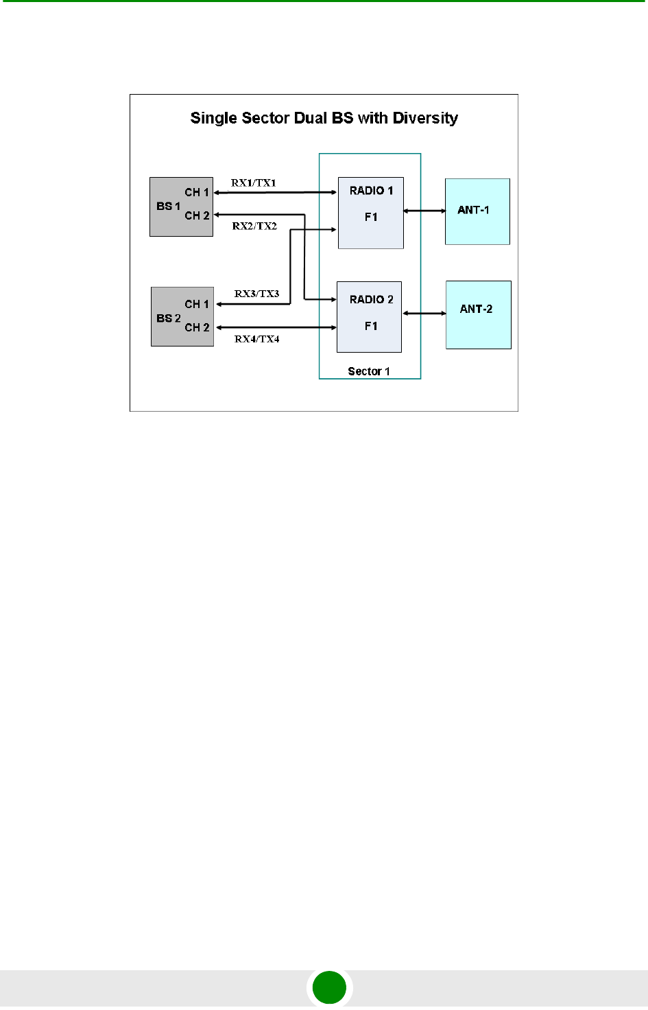
Chapter 4 - Operation and Administration BTS Menu
BreezeMAX Extreme 97 System Manual
Single Sector Dual BS with Diversity
The Single Sector Dual BS with Diversity operation mode is applicable only for
1DIV model units with a license for 20 MHz bandwidth. Two BSs connected to two
internal radios with two Radio Channels per each BS provide a total bandwidth of
14 (applicable only for 3.65 GHz units), or 20 MHz per sector.
Units operating in this mode can use either MIMO Matrix A or MIMO Matrix A&B
Diversity Mode. They can also use MIMO B.
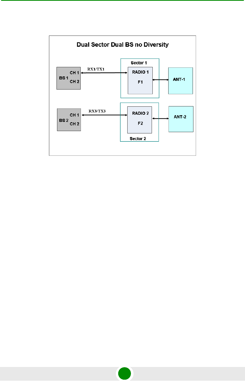
Chapter 4 - Operation and Administration BTS Menu
BreezeMAX Extreme 98 System Manual
Dual Sector Dual BS no Diversity
The Dual Sector Dual BS no Diversity operation mode is applicable only for 2SIS
model units. Each of the two BSs is connected with a single Radio Channel to a
different internal radio, providing a bandwidth of 5, 7 (applicable only for 3.65
GHz units), or 10 MHz per sector.
Only SISO (no diversity) Diversity Mode can be supported by units operating in
this mode.
The available operation modes depend on the supplied configuration and installed
license options:
1SIS units:
»Single Sector Single BS no Diversity
»Single Sector Dual BS no Diversity (available only if 20 MHz license is
installed)
Chapter 4 - Operation and Administration BTS Menu
BreezeMAX Extreme 99 System Manual
1DIV units:
»Single Sector Single BS with Diversity
»Single Sector Dual BS with Diversity (available only if 20 MHz license is
installed)
2SIS units:
»Dual Sector Dual BS no Diversity
4.5.4.5.6 Country Code
The Country Code to be used.
In units operating in the 3.65 GHz band two Country Codes are available:
Universal Country Code supports the entire 3650 to 3700 MHz band, and FCC
Country Code supports the limited band of 3650 to 3675 MHz.
In 5 GHz units several Country Code options are available to support different
local regulations.
The default for all bands is Universal.
The parameters that are affected by the selected Country Code in 5 GHz units are:
Supported frequency range. For details refer to “Frequency” on page 163.
Some Country Codes may support two or more sub-bands, where some
parameters may differ among the supported sub-bands.
Maximum EIRP allowed by regulations. This parameter affects the allowed
range for Tx Power. For more details refer to “Tx Power” on page 165.
Required DFS algorithm. For more details refer to “DFS/DCS” on page 101.
CAUTION
In 5 GHz units, it is the responsibility of the Administrator to verify that the selected Country Code,
and usable frequencies within the selected Country Code, are in accordance with relevant local
regulations.
NOTE
After changing the Country Code to FCC, the Country Code becomes read-only and cannot be
modified.

Chapter 4 - Operation and Administration BTS Menu
BreezeMAX Extreme 100 System Manual
Channel Availability Check Time (applicable only if DFS is supported). For
details refer to “DFS” on page 167.
Table 4-2: Country Code’s Dependent Parameters, 4.9 GHz Units
Country
Code
Frequency
Range
(MHz)
Maximum EIRP (dBm) Supported
DFS
Channel
Availability
Check Time
(sec)
5 MHz BW 10 MHz BW 20 MHz BW
Universal 4900-5350 No Limit No Limit No Limit None NA
Canada 4940-4990 53 56 Not Supported None Not Applicable
5250-5350 22 25 28 FCC 60
FCC 4940-4990 53 56 Not Supported None Not Applicable
5250-5350 22 25 28 FCC 60
Japan 4900-5000 34 34 34 None Not Applicable
5030-5091 34 34 34 None Not Applicable
ETSI 5150-5250 17 20 23 None Not Applicable
5250-5350 17 20 23 ETSI 60
5.1 GHz FAA 5090-5150 No Limit No Limit No Limit None Not Applicable
Table 4-3: Country Code’s Dependent Parameters, 5.4 GHz Units
Country
Code
Frequency
Range
(MHz)
Maximum EIRP (dBm) Supported
DFS
Channel
Availability
Check Time
(sec)
5 MHz BW 10 MHz BW 20 MHz BW
Universal 5470-5950* No Limit No Limit No Limit None Not Applicable
Canada 5470-5725 24 27 30 FCC 60
5725-5850 36 36 36 None Not Applicable
Australia 5470-5600 24 27 30 FCC 600
5650-5725 24 27 30 FCC 600
5725-5850 36 36 36 FCC 600
ETSI 5470-5600 24 27 30 ETSI 60
5600-5650 24 27 30 ETSI 600
5650-5725 24 27 30 ETSI 60
5725-5875 30 33 36 ETSI 60
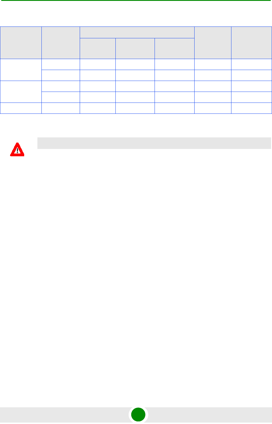
Chapter 4 - Operation and Administration BTS Menu
BreezeMAX Extreme 101 System Manual
* The frequency 5725 MHz is illegal and cannot be used.
4.5.4.5.7 DL / UL Ratio
The DL/UL Ratio defines the ratio of transmit (downlink) time to receive (uplink)
time, in percents.
In the current release, only a ratio of DL = 60%: UL = 40% (complying with slots
ratio of 29,18) is supported.
4.5.4.5.8 DFS/DCS
The DFS/DCS parameters are applicable only for 5 GHz units. The DFS (Dynamic
Frequency Selection) feature is applicable only for units using a Country Code
specifying that DFS must be used. Note that for certain Country Codes DFS
support and Channel Availability Check Time may vary among the relevant
sub-bands supported by the Country Code.
Most parameters of the DFS and DCS features are managed at the sector level (see
“DFS/DCS (5 GHz units only)” on page 166).
The DFS/DCS parameters at the BTS level that are common to both sectors (if
applicable) include:
Random Channel Selection
DFS Frequencies Management Level
FCC 5470-5725 24 27 30 FCC 60
5725-5850 36 36 36 None Not Applicable
UK 5725-5795 30 33 36 ETSI 600
5815-5850 30 33 36 ETSI 600
India 5825-5875 36 36 36 None Not Applicable
CAUTION
If due to either restrictions imposed by local regulations or any other reason you cannot use the
entire frequency band supported by the selected Country Code, you should disable the Random
Channel Selection option (see Section 4.5.4.5.8.1) and use the Usable Frequency option to
define the frequencies manually (see Section 4.7.2.2.2.3)
Table 4-3: Country Code’s Dependent Parameters, 5.4 GHz Units
Country
Code
Frequency
Range
(MHz)
Maximum EIRP (dBm) Supported
DFS
Channel
Availability
Check Time
(sec)
5 MHz BW 10 MHz BW 20 MHz BW

Chapter 4 - Operation and Administration BTS Menu
BreezeMAX Extreme 102 System Manual
4.5.4.5.8.1 Random Channel Selection
The Random Channel Selection parameter defines the method of selecting
channels for scanning by the DCS and/or the DFS mechanisms.
When the DCS mechanism is enabled and Random Channel Selection is enabled,
the list of channels to be scanned is selected randomly from the list of all available
channels in the relevant band according to the Country Code. The number of
channels in the list is defined by the Number of Channels to Scan parameter (see
“Number of Channels to Scan” on page 173). If Random Channel Selection is
disabled, the list of channels will be defined by the user (see “Usable Frequencies”
on page 174).
If DCS is disabled and DFS is enabled, the Random Channel Selection parameter
defines the method of selecting channels for the DFS mechanism.
If Random Channel Selection is enabled, a new channel to be tested is selected
randomly from the list of all available channels in the relevant band. If Random
Channel Selection is disabled, the new channel to be tested will be selected from
the list of channels defined by the user (see “Usable Frequencies” on page 174).
The default is Disable (use the Usable Frequencies list).
4.5.4.5.8.2 DFS Frequencies Management Level
The Frequencies Management Level parameter is not applicable if the selected
Country Code does not support DFS. The DFS Frequencies Management Level
parameter defines the method of handling the DFS Frequencies Status Table (see
“Show Frequencies Status Table” on page 169) in units using Dual Sector Dual BS
no Diversity operation mode. When set to Sector Level, the Frequencies Table of
each sector is managed independently. When set to BTS Level, each sector uses
information about frequencies (Radar Detected/Clear Channel) from the other
one.
The default is Sector Level.
4.5.5 Unit Cont rol
The Unit Control menu of the enables changing the access passwords, resetting
the BTS, reverting to the factory default configuration, managing the SW versions
of the BTS and uploading/downloading files.
The Unit Control menu includes the following options:
Change Password
Reset BTS
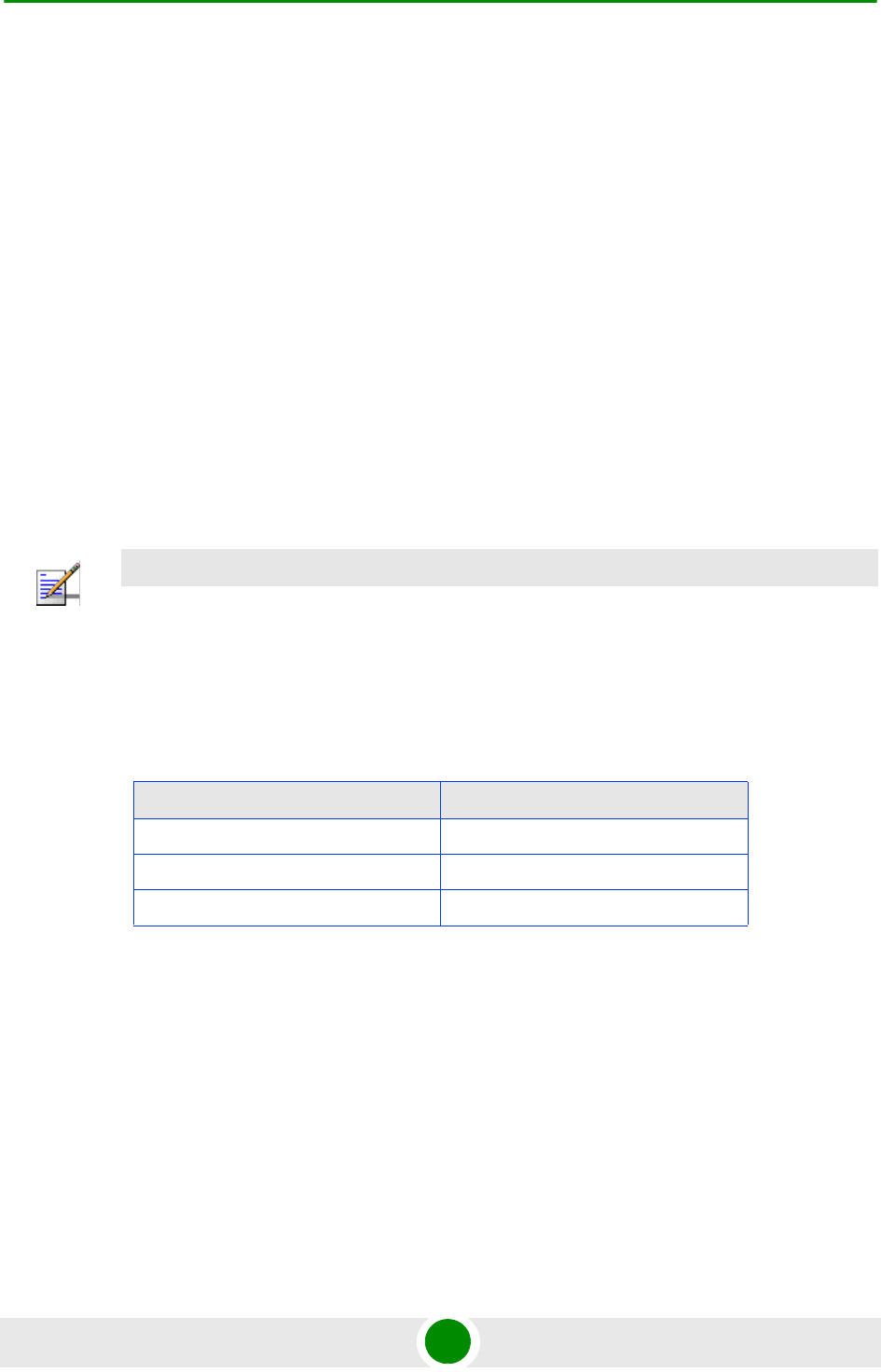
Chapter 4 - Operation and Administration BTS Menu
BreezeMAX Extreme 103 System Manual
Reset to BTS Factory Defaults
SW Version Control
Configuration Files Control
License Files Control
Monitor Inactivity Timeout
4.5.5.1 Change Password
For security and control reasons, the Change Password option is available only for
users with Administration access rights. The Change Password option enables
defining the passwords for each of the three different access levels: Administrator,
Installer and Monitor. After changing the password for a selected access level, you
will be prompted to re-enter the new password for confirmation.
Valid passwords: 1 to 16 printable characters, case sensitive.
The default passwords are:
4.5.5.2 Reset BTS
Select this option to reset the BTS. To avoid unintentional reset, you will be
prompted to confirm the reset request. Changes to some of the configurable
parameters are applied only after reset.
Refer to “Parameters Summary” on page 217 for information on which parameters
are changeable in run time and which changes are applied only after reset.
NOTE
The passwords do not change after performing the Set Factory Defaults operation.
Table 4-4: Default Passwords
Access Level Default Password
Administrator admin
Installer installer
Monitor monitor

Chapter 4 - Operation and Administration BTS Menu
BreezeMAX Extreme 104 System Manual
4.5.5.3 Reset to BTS Factory Defaults
Select this option to set the BTS parameters to their factory default values. All
parameters, excluding the access Passwords, BTS General parameters and BTS
Connectivity parameters (required to enable remote management of the BTS) will
revert to their default values after the next reset. Note that AAA servers and
Authorized Managers will be deleted. Services (if applicable) are not deleted.
Refer to “Parameters Summary” on page 217 for information on the factory default
values of all parameters.
4.5.5.4 SW Version Control
The BTS can contain two SW versions:
Operational: Each time the BTS resets it will reboot using the version defined
as Operational.
Shadow: Normally the Shadow version is the backup version. Each time a new
SW File is downloaded to the BTS, it will be stored as a Shadow version,
replacing the previous Shadow Version.
The typical process of upgrading to a new SW version includes the following steps:
1Download the new SW File to the BTS. It will be stored as the Shadow version.
2Reset and run the BTS from its Shadow version. Note that at this stage, if a
reset were to occur, the BTS will return to the previous Operational version.
3If you want to continue using the new version, swap the Shadow and
Operational versions. The new (currently running) version is now defined as
Operational, and will be used each time the BTS reboots. The previous version
is defined now as Shadow.
Each SW version includes two identifiers:
SW File, which is the name of the downloaded SW file.
SW Version, which provides the SW version number.
The SW Version Control submenu includes the following options:
Show Versions
Show Activation and Status Parameters

Chapter 4 - Operation and Administration BTS Menu
BreezeMAX Extreme 105 System Manual
Load to Shadow
Reset and Run from Shadow
Set Running Version as Operational
4.5.5.4.1 Show Versions
Select this option to view the current available versions and the running version:
Operational SW File
Operational SW Version
Shadow SW File
Shadow SW Version
Running From: Operational or Shadow
Operational Boot SW Version
4.5.5.4.2 Show Activation and Status Parameters
Select this option to view details on the last requested Load to Shadow operation.
The displayed details include:
Process Status: The status/results of the last SW loading process. The status
can be None, In Progress, Completed Successfully, or Failed. For a failed
process the reason is also provided. A process may fail due to various reasons
including TFTP problem, the SW file may already exist in the device, the unit is
running from the Shadow version, there is not sufficient memory space or a
CRC error.
4.5.5.4.3 Load to Shadow
The Load to Shadow option enables initiating a process of loading a new SW file to
the BTS. The loaded SW file will be stored as the new Shadow file.
The following parameters should be configured each time you want to initiate a
Load to Shadow operation:
NOTE
If the unit is running from Shadow, the Load to Shadow operation is not allowed.

Chapter 4 - Operation and Administration BTS Menu
BreezeMAX Extreme 106 System Manual
TFTP Server IP Address: The IP address of the TFTP Server holding the SW
file to be loaded.
File Name: The path to and file name of the SW file to be loaded. A string
comprising 1 to 80 characters.
4.5.5.4.4 Reset and Run from Shadow
Select the Reset and Run from Shadow option to reset the BTS and run the
Shadow version after power up. To avoid unintentional actions you will be
prompted to confirm the request.
4.5.5.4.5 Set Running Version as Operational
When the BTS is running the Shadow version (after selecting Reset and Run from
Shadow), it will boot from the Operational version after the next reset. Select the
Set as Operational option if you want to swap versions so that the running version
will become the Operational version and will be the version to be used after reset.
To avoid unintentional actions you will be prompted to confirm the request.
4.5.5.5 Configuration Files Control
The Configuration Files Control submenu enables creating backup files of the BTS
configuration and uploading/downloading a configuration file from/to the BTS. It
also enables creating and uploading an Event Log file from the BTS.
The Configuration Files Control menu also enables downloading a Country Codes
File or a RFU Heads File to the BTS. The option to download these files enables
loading an updated version of the file (if necessary) without the need to replace the
SW version.
The Configuration Files Control menu includes the following menu options:
Upload Configuration File (Backup File)
Download Configuration File (Restore File)
Show Activation and Status Parameters
4.5.5.5.1 Upload Configuration File (Backup File)
The Upload Configuration File menu includes the following options:
Create Full Configuration File
Create Services (SP & MSF) File

Chapter 4 - Operation and Administration BTS Menu
BreezeMAX Extreme 107 System Manual
Create Event Log File
Activate Upload Operation
4.5.5.5.1.1 Create Full Configuration File
The Create Full Configuration File option enables creating an updated
configuration file that contains all the configurable parameters of the device.
4.5.5.5.1.2 Create Services (SP & MSF) File
The Create Services (SP & MSF) File option enables creating an updated
configuration file that contains all the Services related parameters. This includes
the Service Profiles and Multiple Service Flows with all the relevant components
(QoS Profiles, Service Rules, Classifiers, Service Groups, Service Interfaces and
Forwarding Rules). This option is not applicable for External ASN-GW working
mode.
4.5.5.5.1.3 Create Event Log File
The Create Event Log File option enables creating an updated file that contains all
the events in the device’s event log.
4.5.5.5.1.4 Activate Upload Operation
The Activate Upload Operation option enables initiating a process of uploading a
configuration file to an external TFTP server.
The following parameters should be configured each time you want to initiate a
configuration file upload operation:
File Type: Full Configuration, Services (SP & MSF) File or Event Log File. Note
that the Services (SP & MSF) File option is not applicable for External ASN-GW
working mode.
TFTP Server IP Address: The IP address of the TFTP Server to which the file
should be loaded.
File Path and Name: The path to and file name to be assigned to the uploaded
file in the TFTP server. A string comprising 1 to 80 characters.
The default file names are:
»Full Configuration: backup.res
»Services: profiles_srvc.res
»Event Log: traps_logs.res
Chapter 4 - Operation and Administration BTS Menu
BreezeMAX Extreme 108 System Manual
4.5.5.5.2 Download Configuration File (Restore File)
The Download Configuration File option enables initiating a process of
downloading a file from an external TFTP server.
To initiate a new download operation, configure the following parameters:
File Type: Full Configuration, Services (SP & MSF) File, Country Codes File,
RFU Heads File. Note that the Services (SP & MSF) File option is not applicable
for External ASN-GW working mode.
TFTP Server IP Address: The IP address of the TFTP Server from which the
file should be loaded.
File Path and Name: The path to and file name of the file to be downloaded. A
string comprising 1 to 80 characters.
The default file names are:
»Full Configuration: backup.res
»Services: profiles_srvc.res
To view the results of the download process, use the Show Activation and Status
Parameters option (see below). To fully activate the new configuration, reset the
unit after successful completion of the download operation.
4.5.5.5.3 Show Activation and Status Parameters
Select this option to view details on the last requested upload/download
operations.
4.5.5.6 License Files Control
The License Files Control submenu enables downloading a license file to the BTS.
It also enables viewing the status of the last download operation.
The License Files Control menu includes the following menu options:
Download License File To Unit
NOTE
To avoid loss of connectivity behind a router, the Management Connectivity parameters are not
changed when loading a Full backup file to the BTS. The values of these parameters configured in
the target BTS before the loading process, are maintained.

Chapter 4 - Operation and Administration BTS Menu
BreezeMAX Extreme 109 System Manual
Show Download Status
4.5.5.6.1 Download License File To Unit
The Download License File option enables initiating a process of downloading a
license file from an external TFTP server. The license file must be one that was
prepared for the specific target unit including unique identifiers of the unit such
as MAC address and Serial Number.
To initiate a new download operation, configure the following parameters and
reset the unit:
TFTP Server IP Address: The IP address of the TFTP Server from which the
file should be loaded.
File Path and Name: The path to and file name of the file to be downloaded. A
string comprising 1 to 80 characters.
To view the results of the download process, use the Show Download Status
option (see below). To fully activate the new configuration, reset the unit after
successful completion of the download operation.
4.5.5.6.2 Show Download Status
Select this option to view the status of the last requested download process.
4.5.5.7 Monitor Inactivity Timeout
The Monitor Inactivity Timeout (min) parameter determines the amount of inactive
time following which the unit automatically exits the Monitor program.
The time out duration can range from 0 to 60 minutes. 0 means no inactivity
timeout.
The default value is 10 minutes.
4.5.6 Fa ult Management
The Fault Management menu includes the following options:
Trap Configuration
Show Active Alarm Log Table
Event Log Selection Criteria

Chapter 4 - Operation and Administration BTS Menu
BreezeMAX Extreme 110 System Manual
Show Event Log Table By Selection Criteria
Show All Event Log Table
4.5.6.1 Trap Configuration
The Trap Configuration menu enables viewing current parameters of all traps and
updating the parameters of a selected trap. It also enables viewing traps with
modified parameters (different from the default) and restoring the configuration of
all modified traps to their default values.
The available options are:
Show
Distribution Enabled
Alarm Severity
Suppression Interval
4.5.6.1.1 Show
Select this option to view a list of all traps and their parameters. For each trap,
the following details are displayed:
Trap ID
Name
Distribution Enabled (the default for all traps is Enabled)
Suppression Interval (in seconds. The default is 0, which means no
suppression).
Default Severity*
Current Severity*
* The Severity parameter is applicable only for Alarm traps. It is not applicable to
other trap categories (System Event, Configuration Change Event).
4.5.6.1.2 Distribution Enabled
The Distribution Enabled submenu includes the following options:

Chapter 4 - Operation and Administration BTS Menu
BreezeMAX Extreme 111 System Manual
Show Distribution Disabled Traps: Displays all traps with Distribution
Enabled parameter set to Disable (the default for all traps is Enable).
Update: Enables modifying the Distribution Enabled parameter of a selected
trap.
Restore Distribution Enabled Defaults: Enables restoring the Distribution
Enabled parameter of all traps to the default value (Enable).
4.5.6.1.3 Alarm Severity
The Alarm Severity option is applicable only for Alarm traps.
The Alarm Severity submenu includes the following options:
Show Modified Traps (Severity Changed): Displays the current and default
Severity for all Alarm traps with modified Severity (different from the default).
Update: Enables modifying the Severity parameter of a selected Alarm trap.
The available options are Indeterminate, Critical, Major, Minor, Warning.
Restore Severity Defaults: Enables restoring the default Severity parameter
of all traps to the default value.
4.5.6.1.4 Suppression Interval
The Suppression Interval submenu includes the following options:
Show Modified Traps (Suppression Interval Changed): Displays all traps
with a modified Suppression Interval (the default for all traps is 0).
Update: Enables modifying the Suppression Interval parameter of a selected
trap. The available range is from 0 to 86,400 (seconds). The default is 0, which
means no suppression.
Restore Suppression Interval Defaults: Enables restoring the Suppression
Interval parameter of all traps to the default value (0, meaning no
suppression).
4.5.6.2 Show Active Alarm Log Table
Select to view the currently active alarms. For each active alarm, the following
details are displayed:

Chapter 4 - Operation and Administration BTS Menu
BreezeMAX Extreme 112 System Manual
Seq#: The sequential identification number of the event (trap).
Time: The Date and Time at which the alarm was generated.
MO Type & MO Instance: The Type and Instance (ID number) of the applicable
Managed Object. The possible MO Types are BTS, ASN GW, AAA, Sector, BS,
Radio Channel, GPS, Antenna, MS and MS Service.
Event Type: The type of event (first level of event description).
Probable Cause: The probable cause of the event (second level of event
description).
Specific Problem: The specific problem that caused the event (third level of
event description).
Alarm Severity: The defined severity of the Alarm.
Object Severity: The combined events severity for the Managed Object at the
time the alarm was generated.
For more details on alarms, refer to the Traps and Alarms document.
4.5.6.3 Event Log Selection Criteria
This submenu enables Select to view/update the filtering criteria for the Show
Event Log Table By Selection Criteria display (see “Show Event Log Table By
Selection Criteria” on page 113). For more details on events refer to the Traps and
Alarms document. The configurable filtering criteria are:
Minimum Severity
Last Days
Managed Object Type
Specific Event Category
4.5.6.3.1 Minimum Severity
The Minimum Severity parameter enables defining the minimum severity filter.
Traps whose severity is below the defined severity will not be displayed.

Chapter 4 - Operation and Administration BTS Menu
BreezeMAX Extreme 113 System Manual
The available options are All, Cleared, Indeterminate, Critical, Major, Minor,
Warning.
The default is All, which means that all the traps in the log will be displayed,
including traps indicating that a problem has been resolved (cleared).
4.5.6.3.2 Last Days
The Days parameter enables defining the period for which traps will be displayed.
The available options are from 1 to 31 days. Only traps that occurred within the
last N days, where N is the value selected for this parameter, will be displayed.
The default is 3 day.
4.5.6.3.3 Managed Object Type
The Managed Object Type parameter enable limiting the display to traps
associated with a specific Managed Object type.
The available options are All, BTS, ASN GW, Sector, BS, Radio Channel, GPS,
Antenna, MS and MS Service.
The default is All.
4.5.6.3.4 Specific Event Category
The Specific Event Category parameter enables limiting the display to traps of a
certain category.
The available options are All, Alarm, State Status Change, Configuration Change
Event, System Event.
The default is All.
4.5.6.4 Show Event Log Table By Selection Criteria
Select this option to display details of all events that meet the defined filtering
criteria (see “Event Log Selection Criteria” on page 112). For each event, the
following details are displayed:
Seq#: The sequential identification number of the event (trap).
Time: The Time and Date at which the event was generated.
ID & Name
MO Type & Instance: The Type and Instance (ID number) of the applicable
Managed Object.

Chapter 4 - Operation and Administration BTS Menu
BreezeMAX Extreme 114 System Manual
Event Category
Event Type: The type of event (first level of event description).
Probable Cause: The probable cause of the event (second level of event
description, applicable only for Alarm events).
Specific Problem: The specific problem that caused the event (third level of
event description, applicable only for Alarm events).
Event/Alarm Severity: The defined severity of the Event.
Object Severity: The combined events severity for the Managed Object at the
time at which the event was generated.
Group OID Name: Applicable only for Configuration Change event. Indication
of the changed parameter or the group of parameters where a change
occurred.
4.5.6.5 Show All Event Log Table
Select this option to display all events logged in the device without any filtering.
The displayed details are the same as for “Show Event Log Table By Selection
Criteria” on page 113.
4.5.7 Pe rforma nce Counters
The Performance Counters menu enables viewing and resetting the Traffic
counters of the Data Ethernet interface and of the Data Path. The displayed
information and counters include:
4.5.7.1 Ethernet
General Interface Details
MTU: The size of the largest packet which can be sent/received on the
interface, specified in octets.
Speed and Duplex After Negotiation: The speed of the interface in bits per
second.
BTS MAC Address: The MAC address of the interface.
BTS IP Address: The Management IP address of the BTS.

Chapter 4 - Operation and Administration BTS Menu
BreezeMAX Extreme 115 System Manual
Operational Status: The current operational state of the interface
(Up/Down/Testing). The Testing state indicates that no operational packets
can be passed.
Ethernet Interface Counters:
Received Bytes: The number of octets in valid MAC frames received on this
interface, including the MAC header and FCS.
Received Unicast Packets: The number of packets received on this interface,
which were not addressed to a multicast or broadcast address.
Received Multicast Packets: The number of packets received on this interface,
which were addressed to a multicast address.
Received Broadcast Packets: The number of packets received on this interface,
which were addressed to the broadcast address.
Received And Discarded Packets: The number of received packets which were
chosen to be discarded without being delivered to a higher layer protocol, even
though no errors had been detected. One possible reason for discarding such a
packet could be to free up buffer space.
Transmitted Bytes: The number of octets transmitted in MAC frames on this
interface, including the MAC header and FCS.
Transmitted Unicast Packets: The number of packets transmitted on this
interface, which were not addressed to a multicast or broadcast address.
Transmitted Multicast Packets: The number of packets transmitted on this
interface, which were addressed to a multicast address.
Transmitted Broadcast Packets: The number of packets transmitted on this
interface, which were addressed to the broadcast address.
Packets Discarded On Tx: The number of outbound packets which were
chosen to be discarded without being transmitted even though no errors had
been detected. One possible reason for discarding such a packet could be to
free up buffer space.
Report Flag (ifPromiscuousMode): This object has a value of false(2) if this
interface only accepts packets/frames that are addressed to this station. This

Chapter 4 - Operation and Administration BTS Menu
BreezeMAX Extreme 116 System Manual
object has a value of true(1) when the station accepts all packets/frames
transmitted on the media. The value does not affect the reception of broadcast
and multicast packets/frames by the interface.
4.5.7.2 Data Path
The Data Path counters provides information on data path (customer services)
traffic. The data path counters are:
Received Bytes: The number of received data path octets.
Received Unicast Packets: The number of received data path unicast packets.
Received Multicast Packets: The number of received data path multicast
packets.
Received Broadcast Packets: The number of received data path broadcast
packets.
Received And Discarded Packets: The number of received data path packets
which were chosen to be discarded even though no errors had been detected to
prevent their being deliverable to a higher-layer protocol. One possible reason
for discarding such a packet could be to free up buffer space.
Total Received Packets: The total number of received data path packets.
Packet Dropped from Input Queue: The number of packets that were dropped
from the queue of packets forwarded by the Ethernet interface.
Transmitted Bytes: The number of transmitted data path octets.
Transmitted Unicast Packets: The number of transmitted data path unicast
packets.
Transmitted Multicast Packets: The number of transmitted data path
multicast packets.
Transmitted Broadcast Packets: The number of transmitted data path
broadcast packets.
Packets Discarded On Tx: The number of outbound data path packets which
were chosen to be discarded even though no errors had been detected to

Chapter 4 - Operation and Administration BTS Menu
BreezeMAX Extreme 117 System Manual
prevent their being transmitted. One possible reason for discarding such a
packet could be to free up buffer space.

Chapter 4 - Operation and Administration ASN-GW Menu
BreezeMAX Extreme 118 System Manual
4.6 ASN-GW Menu
The ASN-GW menu includes the following options:
AAA
Services Menu
MAC Access Lists
4.6.1 AAA
4.6.1.1 Working with RADIUS Servers
Managing a large number of users creates the need for significant administrative
support together with careful attention to security, authorization and accounting.
The use of RADIUS (Remote Authentication Dial In User Service) enables
operators to efficiently manage users, supporting AAA functionality:
Authentication (in the form of username & password and security certificates
provided by the user, all checked by the server with an EAP method against a
local flat file database or an external SQL database).
Authorization of requested network services (configuration information
detailing the type of service to use).
Accounting of the granted services usage (for billing, statistical or network
monitoring purposes).
The RADIUS protocol exchanges information between a Network Access Server
(NAS), which needs to authenticate its users, and a shared Authentication server.
A Network Access Server acts as an interface between the users and the RADIUS
server, relaying authentication messages between the two and provisioning the
users with pre-defined services according to the authorization level determined by
the RADIUS server.
The BreezeMAX Extreme has a built-in NAS, referred to as 'ASN'. Based on the
RADIUS and NAS configuration, the BTS has 3 working modes:
Embedded Distributed ASN-GW Centralized Authentication - internal NAS is
used for service provisioning and AAA needs to be handled by a RADIUS
server.

Chapter 4 - Operation and Administration ASN-GW Menu
BreezeMAX Extreme 119 System Manual
Embedded Distributed ASN GW Local Authentication - internal NAS is used
for service provisioning and no AAA is required.
External ASN GW - a 3rd party NAS must handle the service provisioning and
also decide if AAA is required.
In order for the RADIUS server to accept requests from its ASN client, a shared
secret is required to be configured on both parties.
For each new network entry, the ASN initiates the creation of an encrypted
EAP-TTLS (EAP-Tunneled Transport Layer Security) tunnel between the user and
the RADIUS server, then continues relaying messages between the two parties
until the tunnel is complete. The purpose of this tunnel is for the user to send its
credentials (username & password) to the RADIUS server, transparent for the
ASN, using a second authentication protocol, MSCHAPv2 (Microsoft
Challenge-Handshake Authentication Protocol version 2).
The RADIUS server then checks the user's credentials against its database and
decides whether or not the user should be accepted and provisioned with services
by the ASN.
Keep-alive and retry mechanisms are implemented on the ASN to overcome
connectivity problems and loss of packets.
When working in internal ASN authentication mode, the settings and flow of the
authentication and service provisioning process are:
1The user (i.e. MS) needs to have an authentication type (i.e EAP-TTLS) and a
username/password configured in the Registration menu.
2The ASN requires the setting of the AAA client (server IP, shared secret and
keep-alive settings) and the service definition: Multiple Service Flows and
Service Profiles with all their sub-components.
3The configuration of the RADIUS server is the most complex and requires the
following:
»Clients database, containing the IPs and shared secrets of all the ASNs
that connect to it;
»Users database, containing the users' credentials (username & password),
the corresponding services to be provisioned (the names of the Service

Chapter 4 - Operation and Administration ASN-GW Menu
BreezeMAX Extreme 120 System Manual
Profiles and Multiple Service Flows as defined in the ASN), and other
optional attributes that need to be sent to the users (e.g session-timeout).
»General settings configuring the use of EAP-TTLS tunneling and
MSCHAPv2 encryption.
4During initial network entry, the MS first executes initial ranging with the BS,
then exchanges capabilities with the ASN, after which it is asked for identity
by the latter. The EAP process starts at this point. Access-Request &
Access-Challenge messages are exchanged and relayed between the RADIUS
server, ASN and MS, until the tunnel is complete and the user credentials are
securely sent over to the authenticator.
5Depending on the match of the MS's credentials with the RADIUS server's
database, the latter may send back an Access-Accept or an Access-Reject
message to the ASN (to be relayed to the MS).
6In case of successful authentication, the Access-Accept packet contains the
service parameters that the ASN must provision the MS with.
7The ASN checks for the received service parameters and, if defined, starts the
DataPath Registration (MS provisioning).
A RADIUS server can be used for authentication purposes only, for accounting
purposes only, or for both authentication and accounting purposes. In the current
release one server of each type can be defined.
The AAA menu includes the following options:
Show Summary
Configuration
4.6.1.2 Show Summary
Select the Show Summary option to view the configuration and status details for
the general AAA Client parameters and for each of the defined Authentication
and/or Accounting Servers. For more details on these parameters refer to the
relevant sections in the AAA Configuration menu below.
4.6.1.3 Configuration
The AAA Configuration menu includes the following options:
AAA Client

Chapter 4 - Operation and Administration ASN-GW Menu
BreezeMAX Extreme 121 System Manual
Authentication Server
Accounting
4.6.1.3.1 AAA Client
The AAA Client menu enables viewing and updating general parameters that
affect the communication with all RADIUS servers. These parameters include:
Retry Interval (sec)
Maximum Number of Retries
Keep Alive Timeout (sec)
4.6.1.3.1.1 Retry Interval (sec)
The Retry Interval parameter defines the time in seconds to wait before
retransmitting a RADIUS message if no response is received.
The range is 1-30 (seconds).
The default value is 5 (seconds).
4.6.1.3.1.2 Maximum Number of Retries
The Maximum Number of Retries parameter defines the maximum number of
retransmission attempts, before a decision is taken to revert to another server if
configured (not applicable for current release where only one server of each type
can be defined), or give up.
The range is 1-10 (retries).
The default value is 3 (retries).
4.6.1.3.1.3 Keep Alive Timeout (sec)
The NPU maintains a keep alive mechanism with all defined servers. The Keep
Alive Timeout defines the time in seconds between keep alive messages.
The range is 60-180 (seconds).
The default value is 60 (seconds).
NOTE
The BTS sends keep-alive messages to the RADIUS server in the form of Access-Requests with its
own unconfigurable username: "KeepAliveUserNameAndPassword".
Even if this username is not defined in the RADIUS users database, the server will still reply with an
Access-Reject message, thus notifying the ASN that the AAA status is 'up'.

Chapter 4 - Operation and Administration ASN-GW Menu
BreezeMAX Extreme 122 System Manual
4.6.1.3.2 Authentication Server
The Authentication Server menu enables viewing the status and parameters of a
defined Authentication server, adding a new server (in the current release one
server can be defined), updating the parameters of a selected server, or deleting a
server from the database.
The Authentication menu includes the following options:
Show Summary
Select
Add
4.6.1.3.2.1 Show Summary
Select this option to view the current configuration parameters and status details
of a defined Authentication server. The following details are displayed:
Server Address
Server Alias
UDP Port Number
Operation Status: Up or Down (according to the keep alive mechanism)
4.6.1.3.2.2 Select
This option enables selecting an existing Authentication Server for viewing its
status and parameters, updating its parameters, deleting it from the database or
viewing its Statistics counters. The selection is based on the server's IP address.
The available options for a selected server are:
Show: Displays current status and parameters. For information on displayed
details refer to Section 4.6.1.3.2.1).
Update: to update the parameters of the server. For details on the configurable
parameters refer to Section 4.6.1.3.2.3. The Server Address of an existing
server cannot be modified.
Delete: To delete the server from the database.

Chapter 4 - Operation and Administration ASN-GW Menu
BreezeMAX Extreme 123 System Manual
Performance Counters: To display or reset the Performance Counters for this
server. The Performance Counters display traffic information according to the
standard RFC 2618 “RADIUS Authentication Client MIB”, as follows:
»Round Trip Time: The time interval (in hundredths of a second) between
the most recent Access-Reply/Access-Challenge and the Access-Request
that matched it from this server.
»Access Requests: The number of RADIUS Access-Request packets sent to
this server. This does not include retransmissions.
»Access Retransmissions: The number of RADIUS Access-Request packets
retransmitted to this server.
»Access Accepts: The number of RADIUS Access-Accept packets (valid or
invalid) received from this server.
»Access Rejects: The number of RADIUS Access-Reject packets (valid or
invalid) received from this server.
»Access Challenges: The number of RADIUS Access-Challenge packets
(valid or invalid) received from this server.
»Malformed Access Responses*: The number of malformed RADIUS
Access-Response (Access-Accept, Access-Challenge or Access-Reject)
packets received from this server. Malformed packets include packets with
an invalid length. Bad authenticators or Signature attributes or unknown
types are not included.
»Bad Authenticators: The number of RADIUS Access-Response packets
containing invalid authenticators or Signature attributes received from this
server.
»Pending Requests: The number of RADIUS Access-Request packets
destined for this server that have not yet timed out or received a response.
This counter is incremented when an Access-Request is sent and
decremented due to receipt of an Access-Accept, Access-Reject or
Access-Challenge, a timeout or retransmission.
»Timeouts: The number of authentication timeouts to this server. After a
timeout the client may retry to the same server, send to a different server
(not applicable in the current release), or give up. A retry to the same server

Chapter 4 - Operation and Administration ASN-GW Menu
BreezeMAX Extreme 124 System Manual
is counted as a retransmit as well as a timeout. A send to a different server
is counted as a Request as well as a timeout.
»Unknown Types: The number of RADIUS packets of unknown type which
were received from this server on the authentication port.
»Packets Dropped: The number of RADIUS packets which were received
from this server on the authentication port and dropped for any reason.
* Malformed Access Responses counter is not supported in the current release.
4.6.1.3.2.3 Add
Select this option to define a new Authentication server. In the current release one
Authentication server can be defined. You will be prompted to configure the
following parameters:
4.6.1.3.2.3.1 Server Address
The IP address of the Authentication server.
The default is null (IP address must be defined).
The IP Address of an existing server cannot be modified (to change it you must
first delete the server).
4.6.1.3.2.3.2 Server Alias
An reference name for the server.
A string of 1 to 32 printable characters.
The default is null (an alias must be defined).
4.6.1.3.2.3.3 Shared Secret
Shared Secret is the key used for encrypting the User name and Password
transmitted to the RADIUS server(s).
For security and control reasons, the Shared Secret option is available only for
users with Administration access rights, using the Administrator Password to
access the program. For the same security reasons, the Shared Secret is displayed
as a series of asterisks, and when defining it for the first time or updating it, the
user is prompted to re-enter the new Shared Secret for confirmation.
Valid Shared Secret: 1 to 16 printable characters, case sensitive.
The default Shared Secret is null (Shared Secret must be defined).

Chapter 4 - Operation and Administration ASN-GW Menu
BreezeMAX Extreme 125 System Manual
4.6.1.3.2.3.4 UDP Port Number
Specifies the UDP port number used by the RADIUS server for authentication
transactions.
Valid values: 1 to 65535.
The default value is 1812 (RFC 2865 requirement).
The UDP Port Number of an existing server cannot be modified (to change it you
must first delete the server).
4.6.1.3.3 Accounting
The Accounting menu enables viewing the status and parameters of a defined
Accounting server, adding a new server (in the current release one server can be
defined), updating the parameters of an existing server, or deleting a server from
the database.
The Accounting menu includes the following options:
Show Summary
Select
Add
4.6.1.3.3.1 Show Summary
Select this option to view the current status and parameters of a defined
Accounting server. The following details are displayed:
Server Address
Server Alias
UDP Port Number
Operation Status: Up or Down (according to the keep alive mechanism)
4.6.1.3.3.2 Select
This option enables selecting an existing Accounting Server for viewing its status
and parameters, updating its parameters, deleting it from the database or viewing
its Statistics counters. The selection is based on the server's IP address.
The available options for a selected server are:

Chapter 4 - Operation and Administration ASN-GW Menu
BreezeMAX Extreme 126 System Manual
Show: Displays current status and parameters. For information on displayed
details refer to Section 4.6.1.3.3.1).
Update: to update the parameters of the server. For details on the configurable
parameters refer to Section 4.6.1.3.3.3. The Server IP Address of an existing
server cannot be modified)
Delete: To delete the server from the database.
Performance Counters: To display or reset the Performance Counters for this
server. The Performance Counters display traffic information according to the
standard RFC 2620 “RADIUS Accounting Client MIB”, as follows:
»Round Trip Time: The time interval (in hundredths of a second) between
the most recent Accounting-Response and the Accounting-Request that
matched it from this server.
»Requests: The number of RADIUS Accounting-Request packets sent to this
server. This does not include retransmissions.
»Retransmissions: The number of RADIUS Accounting-Request packets
retransmitted to this server. Retransmissions include retries where the
Identifier and Acct-Delay have been updated, as well as those in which
they remain the same.
»Responses: The number of RADIUS packets received on the accounting
port from this server.
»Malformed Responses*: The number of malformed RADIUS
Accounting-Response packets received from this server. Malformed
packets include packets with an invalid length. Bad authenticators or
unknown types are not included.
»Bad Authenticators: The number of RADIUS Accounting-Response
packets containing invalid authenticators received from this server.
»Pending Requests: The number of RADIUS Accounting-Request packets
sent to this server that have not yet timed out or received a response. This
counter is incremented when an Accounting-Request is sent and
decremented due to receipt of an Accounting-Response, a timeout or
retransmission.
»Timeouts: The number of accounting timeouts to this server. After a
timeout the client may retry the same server, send to a different server (not

Chapter 4 - Operation and Administration ASN-GW Menu
BreezeMAX Extreme 127 System Manual
applicable in the current release), or give up. A retry to the same server is
counted as a retransmit as well as a timeout. A send to a different server is
counted as an Accounting- Request as well as a timeout.
»Unknown Types: The number of RADIUS packets of unknown type which
were received from this server on the accounting port.
»Packets Dropped: The number of RADIUS packets which were received
from this server on the accounting port and dropped for any reason.
* Malformed Responses counter is not supported in the current release.
4.6.1.3.3.3 Add
Select this option to define a new Accounting server. In the current release one
Accounting server can be defined. You will be prompted to configure the following
parameters:
4.6.1.3.3.3.1 Server IP Address
The IP address of the Accounting server.
The default is null (IP address must be defined).
4.6.1.3.3.3.2 Server Alias
An optional reference name for the server.
A string of 1 to 32 printable characters.
The default is null (an empty string).
4.6.1.3.3.3.3 Shared Secret
Shared Secret is the key used for encrypting the User name and Password
transmitted to the RADIUS server(s).
For security and control reasons, the Shared Secret option is available only for
users with Administration access rights, using the Administrator Password to
access the program. The Shared Secret cannot be changed using SNMP. For the
same security reasons, the Shared Secret is displayed as a series of asterisks, and
when defining it for the first time or updating it, the user is prompted to re-enter
the new Shared Secret for confirmation.
Valid Shared Secret: 1 to 16 printable characters, case sensitive.
The default Shared Secret is null (Shared Secret must be defined).
4.6.1.3.3.3.4 UDP Port Number
Specifies the UDP port number used by the RADIUS server for accounting
transactions.

Chapter 4 - Operation and Administration ASN-GW Menu
BreezeMAX Extreme 128 System Manual
Valid values: 1 to 65535.
The default value is 1813 (RFC 2866 requirement).
The UDP Port Number of an existing server cannot be modified (to change it you
must first delete the server).
4.6.2 Services M enu
4.6.2.1 Introduction
Services are logical entities residing on the ASN to ensure end to end connectivity
based on QoS, forwarding rules and classifiers. Services should be defined from
bottom up, using the following order:
1Forwarding Rule: Defines the behavior in the wireless broadcast domain.
2Service Interface: Defines the parameters that affect connectivity between the
BTS and the backbone.
3Service Group: Defines the connectivity and functionality of operating with
external elements (DHCP Server, AAA Server).
4Multiple Service Flow: Defines the flow classification and prioritization over the
wireless link.
5Service Profile: Defines the QoS part of a generic service contract between an
operator and a subscriber.
6MS Service (applicable only for local authentication): Defines the provisioning
of a Service (a pair of one Service Profile and one Multiple Service Flow) to a
specific MS.
The system is supplied with a set of default service components to support typical
Management, IP CS Data and Ethernet CS Data services (see “MSs Default
Services” on page 151).
4.6.2.2 Common Operations in Services Menus
The menu options available in the Services menu enable viewing, editing, deleting
and adding applicable entities, such as Service Profiles, QoS Profiles, etc.
Some or all of the following options are available in the Services menus:
Show Summary: Select this option to see the current details of all entities in
the applicable menu.

Chapter 4 - Operation and Administration ASN-GW Menu
BreezeMAX Extreme 129 System Manual
Select From List: Select this option to view all defined entities in the
applicable menu sorted by the entity ID. The entity ID is an identifier attached
automatically to each new entity. You can select a specific entity by its ID. This
will open the Selected Entity menu with the Show, Update and Delete options
described below.
Select By...(or Select From a specific list): This option enables selecting an
entity by a specific identifier such as Name or ID. Select this option and enter
the appropriate parameter's value to access the menu for a selected entity.
This will typically enable you to choose from the following options:
»Show: Select this option to view the details of the selected entity.
»Update: Select this option to edit the details of the selected entity.
»Delete: Select this option to remove the selected entity from the database.
Add: Select this option to add a new entity to the database.
The Services menu includes the following options:
MSs Services
Service Profiles
Multiple Service Flows
Service Groups
Service Interfaces
Forwarding Rules
MSs Default Services
4.6.2.3 MSs Services
The MSs Services menu enables managing the provisioning of Services to MSs.
MSs Services can be created or updated only in Embedded Distributed ASN-GW
Local Authentication working mode.

Chapter 4 - Operation and Administration ASN-GW Menu
BreezeMAX Extreme 130 System Manual
The MS services table connects between a single Service Profile and a single
Multiple Service Flow. Up to 3 such pairs can (services) can be created per MS
(MAC address).
The number of QoS Profiles assigned to the selected Service Profile must be
identical to the number of Service Rules assigned to the selected Multiple Service
Flow.
The MS Service parameters are:
MS MAC Address
Service Number
Admin Status
Multiple Service Flow Name
Service Profile Name
The menu for a selected MS Service enables also viewing the Service Counters for
the selected MS Service.
4.6.2.3.1 MS MAC Address
The MAC Address of the MS to which the Service is provisioned.
4.6.2.3.2 Service Number
The Number of the Service. Each MS can be provisioned with up to 3 Services,
with Numbers from 1 to 3.
4.6.2.3.3 Admin Status
The Admin Status of the Service: Enable or Disable. A disabled Service will not be
available to the end-user, but its properties are maintained in the database
allowing quick renewal of the Service.
4.6.2.3.4 Multiple Service Flow Name
The name of the Multiple Service Flow associated with the Service. Must be a
name of a previously defined Multiple Service Flow that exists in the database.
IMPORTANT
The MAC Address must be one that exists in the database. Refer to ““MS Menu”
on page 212 for details on manually adding MSs to the database.

Chapter 4 - Operation and Administration ASN-GW Menu
BreezeMAX Extreme 131 System Manual
4.6.2.3.5 Service Profile Name
The name of the Service Profile associated with the Service. Must be a name of a
previously defined Service Profile that exists in the database.
A Management Service Profile must be associated with each MS. Up to two
additional Service Profiles can be associated with each MS (all combinations are
allowed, including two Service Profiles of the same type).
4.6.2.3.6 MS Service Counters
The Service Counters for a selected MS Service include the following counters for
each existing Service Rule:
Service Rule Number
UL Total Received Bytes
UL Total Received Packets
UL Total Lost Packets
DL Total Transmitted Bytes
DL Total Transmitted Packets
DL Total Lost Packets
4.6.2.4 Service Profiles
The Service Profiles menu enables managing Service Profiles, including the QoS
Profile(s) associated with each Service Profile. The menu for a selected Service
Profile (after the basic parameters are defined) enables access to the QoS Profiles
submenu. At least one QoS Profile must be assigned to each Service Profile, up to
a maximum of four QoS Profiles per Service Profile. For details refer to QoS
Profiles (Section 4.6.2.5) below.
The Service Profile basic parameters are:
Service Profile ID
Service Profile Name
Service Profile Type

Chapter 4 - Operation and Administration ASN-GW Menu
BreezeMAX Extreme 132 System Manual
HARQ Repetitions (Read-only)
4.6.2.4.1 Service Profile ID
This is an auto-sequential number from 1 to a maximum of 64, generated
automatically during creation of a new Service Profile.
4.6.2.4.2 Service Profile Name
The Name of the Service Profile. A unique string of 1 to 32 characters.
4.6.2.4.3 Service Profile Type
The type of a service using the Service Profile. The options available in the current
release are:
Management
Data
PPPoE
VoIP
Reliable Video
4.6.2.4.4 HARQ Repetitions
HARQ (Hybrid-ARQ) is an ARQ (Automatic Repeat reQuest) mechanism that is
implemented at the physical layer together with FEC, providing improved link
performance over traditional ARQ at the cost of increased implementation
complexity. HARQ uses a combination of FEC and ARQ, where blocks of data,
along with a CRC code, are encoded using a FEC coder before transmission;
retransmission is requested if the decoder is unable to correctly decode the
received block. When a retransmitted coded block is received, it is combined with
the previously detected coded block and fed to the input of the FEC decoder.
Combining the two or more received versions of the code block improves the
chances of correctly decoding.
The WiMAX standard supports this by combining an N-channel stop and wait
ARQ along with a variety of supported FEC codes. Doing multiple parallel
channels of HARQ at a time can improve the throughput, since when one HARQ
process is waiting for an acknowledgment, another process can use the channel to
send some more data. WiMAX supports signaling mechanisms to allow
asynchronous operation of HARQ and supports a dedicated acknowledgment
channel in the uplink for ACK/NACK signaling. Asynchronous operations allow

Chapter 4 - Operation and Administration ASN-GW Menu
BreezeMAX Extreme 133 System Manual
variable delay between retransmissions, which provides greater flexibility for the
scheduler.
In the current release HARQ is not configurable: It is enabled by default with 4
repetitions for Management, Data, PPPoE, and Reliable Video Services Profiles,
and with 1 repetition for VoIP Service Profiles.
4.6.2.5 QoS Profiles
The QoS Profile submenu option for a selected Service Profile enables managing
the QoS Profiles assigned to the Service Profile. At least one QoS Profile must be
assigned to each Service Profile, up to a maximum of four QoS Profiles per Service
Profile.
Each QoS Profile includes the following components:
QoS Profile ID
Uplink QoS Type
Uplink CP
Uplink QoS Parameter(s) - according to Uplink QoS Type
Downlink QoS Type
Downlink CP
Downlink QoS Parameter(s)- according to Downlink QoS Type
4.6.2.5.1 QoS Profile ID
This is an auto-sequential number from 1 to a maximum of 4, generated
automatically during creation of a new QoS Profile for the specific Service Profile.
4.6.2.5.2 Uplink/Downlink QoS Type
The type of QoS mechanism in the uplink/downlink when the QoS Profile is used.
In the current release the available options are BE (Best Effort), NRT (Non Real
Time), and ERT (Extended Real Time).
BE (Best Effort) service is designed to support data streams, such as Web
browsing, that do not require a minimum service-level guarantee.
NRT (Non Real Time) is designed to support delay-tolerant data streams, such as
FTP, that require variable-size data grants at a minimum guaranteed rate.

Chapter 4 - Operation and Administration ASN-GW Menu
BreezeMAX Extreme 134 System Manual
ERT (Extended Real Time) is designed to support real-time applications, such as
VoIP with silence suppression, that have variable data rates but require
guaranteed data rate and delay.
4.6.2.5.3 Uplink/Downlink CP
The Committed Priority in the uplink/downlink.
For BE QoS CP is not configurable and is set to 0.
For NRT QoS the supported range is from 1 to 2.
For ERT QoS the supported range is from 3 to 7.
The CP parameter affects the Committed Time (CT) as follows:
Maximum Latency is equal to CT.
Unsolicited Grant Interval (UGI) for ERT QoS is CT/2. Note that UGI functionality
of periodic allocations is applicable only for the uplink traffic.
Unsolicited Polling Interval (UPI) for NRT QoS is CT/2. Note that UPI functionality
of periodic polling is applicable only for uplink traffic.
4.6.2.5.4 Uplink/Downlink QoS Parameters (CIR/MIR)
The availability of specific QoS parameters depend on the selected QoS Type as
follows:
Table 4-5: Committed Time
CP (Committed Priority) CT (Committed Time)
0 1000ms
1 2000ms
260ms
3 120ms
480ms
560ms
640ms
720ms
Table 4-6: QoS Parameters
QoS Type QoS Parameters
BE MIR

Chapter 4 - Operation and Administration ASN-GW Menu
BreezeMAX Extreme 135 System Manual
CIR is the minimum information transfer rate that the system is committed to
transfer under normal conditions (minimum reserved traffic rate).
MIR is the maximum information rate that the system will allow for the
connection (maximum sustained traffic rate).
The CIR/MIR rate is averaged over a minimum increment of time, which is defined
by the CT parameter.
The range of CIR/MIR for all Downlink flows and for Uplink BE and NRT flows is
from 32 (the default) to 54,000 Kbps.
For Uplink ERT flows where we have the advantage of periodic allocations, the
UGI (equal to CT/2) and the range for MIR are as follows:
The uplink CIR of eRT will be set internally to the value configured for MIR
In the Downlink of ERT flows UGI has no meaning and the configuration range for
CIR and MIR is 32-54000 Kbps. However, ERT QoS offers the advantages of
higher priority and lower latency values than BE or NRT QoS.
MIR cannot be lower than CIR for the same direction.
4.6.2.6 Multiple Service Flows
The Multiple Service Flows menu enables managing Multiple Service Flows,
including the Service Rule(s) associated with each Multiple Service Flow. The
menu for a selected Multiple Service Flow (after the basic parameters are defined)
enables access to the Service Rules submenu. At least one Service Rule must be
assigned to each Multiple Service Flow, up to a maximum of four Service Rules
NRT CIR, MIR
ERT CIR, MIR
Table 4-7: MIR values for Uplink ERT QoS
CP MIR (Kbps) UGI (ms)
3 32-272 60
4 32-409 40
5 32-545 30
6 32-818 20
7 32-1637 10
Table 4-6: QoS Parameters
QoS Type QoS Parameters

Chapter 4 - Operation and Administration ASN-GW Menu
BreezeMAX Extreme 136 System Manual
per Multiple Service Flow. For details refer to Service Rules (Section 4.6.2.7)
below.
The Multiple Service Flow basic parameters are:
Multiple Service Flow ID
Multiple Service Flow Name
Service Group Name
4.6.2.6.1 Multiple Service Flow ID
This is an auto-sequential number from 1 to a maximum of 1030, generated
automatically during creation of a new Multiple Service Flow.
4.6.2.6.2 Multiple Service Flow Name
The Name of the Multiple Service Flow. A unique string of 1 to 32 characters.
4.6.2.6.3 Service Group Name
The name of the Service Group associated with the Multiple Service Flow. Must be
a name of a previously defined Service Group that exists in the database.
4.6.2.6.4 Service Operation Mode
The Service Operation Mode parameter defines whether NAT routing is used by
the MS or behind the MS (Router mode) or not (Bridge mode).
In Bridge mode, the ASN-GW learns the IP address assigned to the MS, and
associate with this IP address the VLAN ID defined in the Service Interface
specified in the Service Rule that matches the connection used for DHCP.
In Router mode, the ASN-GW checks all the Router mode Multiple Service Flows
assigned to the same MS that use the same Service Group as the relevant
connection, and associate with the IP address all VLAN IDs defined in relevant
Service Interfaces. Router mode is applicable only for IP CS services.
4.6.2.7 Service Rules
The Service Rules menu enables managing Service Rules, including the
Classifier(s) associated with each Service Rule. The menu for a selected Service
Rule (after the basic parameters are defined) enables access to the Classifiers
submenu. For Service Rules of a Multiple Service Flow assigned to a PPPoE
Service, no Classifiers should be defined. For all other Service Rules, at least one
Classifier must be assigned to each Service Rule, up to a maximum of five
Classifiers per Service Rule. For details refer to Classifiers (Section 4.6.2.8) below.

Chapter 4 - Operation and Administration ASN-GW Menu
BreezeMAX Extreme 137 System Manual
When either defining a new Service Rule and its components or updating an
existing one, note that a Multiple Service Flow can include a maximum of one
Service Rule with a Classifier of type Any.
The Service Rule basic parameters are:
Service Rule ID
Service Interface Name
4.6.2.7.1 Service Rule ID
This is an auto-sequential number from 1 to a maximum of 4, generated
automatically during creation of a new Service Rule for a specific Multiple Service
Flow.
4.6.2.7.2 Service Interface Name
The Name of the Service Interface associated with the Service Rule. Must be one of
the previously defined Service Interfaces that exists in the database. An Ethernet
CS Service Interface can be associated only to a Multiple Service Flow with a
Bridge Service Operation Mode.
4.6.2.8 Classifiers
The Classifiers submenu option for a selected Service Rule enables managing the
Classifier(s) assigned to the Service Rule. For Service Rules of a Multiple Service
Flow assigned to a PPPoE Service, no Classifiers should be defined. For all other
Service Rules, at least one Classifier must be assigned to each Service Rule, up to
a maximum of five Classifiers per Service Rule.
Note the following rules when either defining a new Classifier or updating an
existing one:
A maximum of one Classifier of type Any for a certain direction can be
associated with each MS. This means:
»A Service Rule can include a maximum of one Classifier of type Any for a
certain direction.
»A Multiple Service Flow can include a maximum of one Service Rule with a
Classifier of type Any for a certain direction.
»An MS can have a maximum of one Service associated with a Multiple
Service Flow with a Service Rule with a Classifier of type Any for a certain
direction.

Chapter 4 - Operation and Administration ASN-GW Menu
BreezeMAX Extreme 138 System Manual
Overlapping of range values is not allowed. This is applicable for:
»The Service Rule level: The range values defined for any Classifier of a
certain Type for a certain direction assigned to a Service Rule should not
overlap with the range values of other Classifiers of the same Type for the
same direction assigned to the same Service Rule.
»The Multiple Service Flow level: The range values defined for any Classifier
of a certain Type for a certain direction assigned to a Service Rule of a
certain Multiple Service Flow, should not overlap with the range values of
any Classifiers of the same Type for the same direction assigned to other
Service Rules assigned to the same Multiple Service Flow.
»The MS level: The range values defined for any Classifier of a certain Type
for a certain direction assigned to a Service Rule of any Multiple Service
Flow assigned to any Service for a certain MS, should not overlap with the
range values of any Classifiers of the same Type for the same direction
assigned to any of the Service Rules assigned to other Multiple Service
Flows that are assigned to other Services for the same MS.
Each Classifier includes the following components:
4.6.2.8.1 Uplink/Downlink Classifier Type
This parameter defines the type of classifier to be used in the applicable direction.
Different classifier types may be defined for the uplink and downlink directions.
The available options are Any, DSCP, VLAN ID and VLAN Priority. If the CS Type
of the Service Interface assigned to the Service Rule is IP CS, then only Any and
DSCP types are supported.
For a Classifier Type Any there are no other parameters.
Table 4-8: Classifier Parameters
Uplink/Downlink
Classifier Type
Uplink/Downlink
Classifier Parameter 1
Uplink/Downlink
Classifier Parameter 2
Any - -
DSCP Lowest DSCP Value Highest DSCP Value
VLAN ID VLAN ID Value N/A
VLAN Priority Lowest VLAN Priority Value Highest VLAN Priority Value

Chapter 4 - Operation and Administration ASN-GW Menu
BreezeMAX Extreme 139 System Manual
4.6.2.8.2 Uplink/Downlink Classifier Parameter 1 and 2
Each Classifier of type DSCP or VLAN Priority can define a range of value to be
used for classification. These parameters defines the lowest and highest values in
the range. The applicable range values are:
The value configured for Parameter 2 for a certain direction cannot be lower than
the value configured for Parameter 1 for the same direction.
Note that the value configured for any of these parameters cannot be within the
ranges defined for other Classifiers of the same Type and Direction assigned to
either the same Service Rule, or to other Service Rules assigned to the same
Multiple Service Flow, or to any of the Service Rules assigned to other Multiple
Service Flows that are assigned to other Services for the same MS.
For each VLAN ID Classifier, a single value in the range 1-4094 can be configured
for Parameter 1 (Parameter 2 is not applicable for VLAN ID Classifier). The value
configured for a VLAN ID classifier must differ from the values defined for other
Classifiers of the same Type and Direction assigned to either the same Service
Rule, or to other Service Rules assigned to the same Multiple Service Flow, or to
any of the Service Rules assigned to other Multiple Service Flows that are
assigned to other Services for the same MS.
4.6.2.9 Service Groups
A Service Group defines the DHCP mode to be used for acquiring IP address
configuration for the MS provisioned with the relevant Service and, if applicable,
for other devices behind the MS. It also defines additional parameters that affect
the communication between the ASN-GW and an external DHCP server, if
applicable. The Service Group’s parameters includes also the Attributes to be
used for communication with a RADIUS Accounting server.
Table 4-9: Uplink/Downlink Classifier Parameters Range Values
Uplink/Downlink Classifier
Type
Uplink/Downlink Classifier Parameter
1 and 2
DSCP 0-63
VLAN Priority 0-7

Chapter 4 - Operation and Administration ASN-GW Menu
BreezeMAX Extreme 140 System Manual
Up to 10 different Service Groups can be defined.
In addition to managing Service Groups, the Service Groups Menu enables also
viewing the Lease Times (see “Show DHCP Lease Times” on page 146)
Each Service Group includes the following parameters:
4.6.2.9.1 Service Group ID
This is an auto-sequential number from 1 to a maximum of 10, generated
automatically during creation of a new Service Group.
4.6.2.9.2 Service Group Name
The Name of the Service Group. A unique string of 1 to 32 characters.
4.6.2.9.3 DHCP Type
The DHCP operation mode supported by the unit:
None: DHCP is not used. This mode is applicable for Ethernet CS service
interfaces. The ASN-GW learns the IP parameters by “listening” to DHCP
processes.
Transparent: Typically used with IP CS service interfaces. The MS
communicates directly with a DHCP server without involving the ASN-GW.
NOTE
All MSs using IP-CS service flows will be de-registered so that clients will be forced to renew their IP
bindings in the following cases:
1. DHCP Type is changed and the old type is other than None (if it is none, the BS just forwards
DHCP traffic without taking any action).
2. DHCP Type hasn’t changed, but it is configured as Server and at least one of the following
networking values has changed:
Pool IP address
Pool Subnet Mask
DHCP IP Address
A DNS IP Address
Lease Time
CPE Management Server
Default Gateway

Chapter 4 - Operation and Administration ASN-GW Menu
BreezeMAX Extreme 141 System Manual
Forward With Option 82: This is practically the same as Transparent mode
(see above), with the exception that the ASN-GW inserts Option 82 (Relay
Agent Information) to DHCP messages forwarded to the backbone and removes
them from received messages before forwarding them to the MS. Any DHCP
discovery/request message coming from the user that includes option 82 will
be dropped.
Relay With Option 82: The ASN-GW serves as a relay for DHCP messages
between the MS and a known DHCP server. The implementation complies with
RFC-2131 and RFC-3046. Any DHCP discovery/request message coming from
the user that includes option 82 will be dropped.
Server: The ASN-GW acts as a DHCP server.
4.6.2.9.4 Nomadic Mode
The Nomadic Mode parameter ia applicable for all DHCP operation modes. It
defines whether nomadic operation of the MS should be supported by the
provisioning and accounting mechanism. When disabled, the provisioned services
should be supported only when the MS is served by a specific BTS. When enabled,
provisioned services should not be restricted to a specific BTS.
The default is Disable.
4.6.2.9.5 Attribute 31
The Attribute 31 parameter is applicable for all DHCP operation modes, defining
information that should be used by the embedded RADIUS client.
Attribute 31 specifies the Calling Station ID information to be included in RADIUS
Access-Request and Accounting-Request messages. This feature enables service
providers to provide more information about the call originator to the RADIUS
server(s). The information provided by this feature can also be used for additional
security checks.
In RADIUS Access-Request messages Attribute 31 is set by default to CPE MAC
Address. The configurable Attribute 31 parameter is applicable only for RADIUS
accounting messages.
The available options for DHCP None, Transparent, and Server modes are None,
CPE MAC Address and CPE Fully Qualified Domain Name.
For DHCP Relay/Forward with Option 82 modes the available options are None,
CPE MAC Address and the option selected for the Option 82 Sub Type 2
parameter (see “Option 82 Sub Type 2” on page 145). This means that the CPE
Fully Qualified Domain Name option is available only if this is the selected option
for Option 82 Sub Type 2).

Chapter 4 - Operation and Administration ASN-GW Menu
BreezeMAX Extreme 142 System Manual
The default option is CPE MAC Address.
4.6.2.9.6 Attribute 32
The Attribute 32 parameter is applicable for all DHCP operation modes, defining
information that should be used by the embedded RADIUS client.
Attribute 32 specifies the NAS Identifier information to be included in RADIUS
Access-Request and Accounting-Request messages. This feature enables service
providers to provide more information about the device serving the call originator
to the RADIUS server(s). The information provided by this feature can also be used
for additional security checks.
In RADIUS Access-Request messages Attribute 32 is set by default to BS ID if
Nomadic Mode is set to Disable. Attribute 32 is not used if Nomadic Mode is
enabled. The configurable Attribute 32 parameter is applicable only for RADIUS
accounting messages.
The available options for DHCP None, Transparent, and Server modes are None,
BTS MAC Address, GIADDR, Service Interface VLAN, Management IP Address, BS
ID, BTS Name, Free Text. If the Free Text option is selected, a unique string of 1 to
32 characters should be specified.
For DHCP Relay/Forward with Option 82 modes the available options are None,
BS ID and the option selected for the Option 82 Sub Type 1 parameter (see
“Option 82 Sub Type 1” on page 145).
The default option is None.
4.6.2.9.7 Attribute 32 Free Text
Applicable only if the selected option for Attribute 32 is Free Text. A string of 1 to
32 characters to be used as a unique NAS ID in relevant RADIUS accounting
messages.
The default is an empty string (must be configured to a valid value if Free Text is
the selected option for Attribute 32).
4.6.2.9.8 Interface IP Address
Applicable for Transparent and Forward with Option 82 DHCP Modes. This is the
local IP address for the Service Group. Will be the source IP to ARP requests for
gateway MAC address.
The default is the Management Interface IP Address. In this case all other relevant
parameters (Interface Subnet Mask, Default Gateway, VLAN ID) must be the
default values (Management Interface parameters).

Chapter 4 - Operation and Administration ASN-GW Menu
BreezeMAX Extreme 143 System Manual
4.6.2.9.9 Interface Subnet Mask
Applicable for Transparent and Forward with Option 82 DHCP Modes. This is the
subnet used with the Interface IP Address.
The default is the Management Interface Subnet Mask.
4.6.2.9.10 Default Gateway
The Default Gateway parameter is applicable for all DHCP operation modes,
excluding None. It defines the IP address of the gateway to be used by the service.
This feature, enabling separation between traffic of different services, is applicable
only for IP CS services.
The default address is 0.0.0.0. In this case, the Management Default Gateway is
used.
If the Management Default Gateway is used, the local IP address on the interface
(GI IP Address - for Relay, or Interface IP Address - for Transparent and Forward)
must be the Management IP, and the VLAN ID must be the same as the
Management VLAN ID.
4.6.2.9.11 VLAN ID
The VLAN ID parameter is applicable for all DHCP operation modes, excluding
None. It defines the VLAN ID to be used for communication with the Service
Group Gateway.
The range is from 0 to 4094 or 4096 for No VLAN.
The default value is 0. In this case, the Management VLAN ID is used. Otherwise,
it must be a valid VLAN ID configured on a Service Interface.
If the Management VLAN ID is used, the local IP address on the interface (GI IP
Address - for Relay, or Interface IP Address - for Transparent and Forward) must
be the Management IP, and the Default Gateway must be the same as the
Management Default Gateway.
4.6.2.9.12 VLAN Priority
The VLAN Priority parameter is applicable for all DHCP operation modes,
excluding None. It defines the VLAN Priority to be used with the VLAN ID. Not
applicable if VLAN ID is set to none (4096)
The range is from 0 to 7.
If the VLAN ID is set to 0 (the default, meaning that Management VLAN ID is
used), the VLAN Priority is not configurable and it will be set to the value of the
Management VLAN Priority.

Chapter 4 - Operation and Administration ASN-GW Menu
BreezeMAX Extreme 144 System Manual
4.6.2.9.13 DHCP Server Specific Parameters
The following parameters are applicable only for Service Groups with DHCP Type
Server:
4.6.2.9.13.1 DHCP Pool IP Address
The network IP address in the IP addresses pool. Addresses in the pool cannot
include an address that is already in use for another Service Group (Server IP or
GI IP Address). The IP address to be allocated for a new client will be the first free
address from the subnet. IP address will be released if the lease time (see below)
has expired without receiving a renew request from the client.
4.6.2.9.13.2 DHCP Pool Subnet Mask
The subnet mask that together with the DHCP Pool IP Address define the range of
addresses in the IP pool. The pool must not be in use by another Service Group.
4.6.2.9.13.3 DHCP IP Address
The local IP address of the server interface. Can be any IP address from the DHCP
Pool.
4.6.2.9.13.4 DNS 1 IP Address
The first DNS IP address to be provided by the DHCP server (optional).
The default is 0.0.0.0 (none). In this case DNS information will not be included in
the DHCP packet. Cannot be the same as Default Gateway or DHCP IP Address.
4.6.2.9.13.5 DNS 2 IP Address
The second DNS IP address to be provided by the DHCP server (optional, may
equal DNS 1 IP Address). The default is 0.0.0.0 (none). Cannot be the same as
Default Gateway or DHCP IP Address.
4.6.2.9.13.6 DHCP Lease Time
The lease time for IP allocation by the server. If a renew request is not received
within the specified lease time the IP address will be released and returned to the
pool.
The range is from 0 to 4294967295 seconds. 0 means infinite (no lease time).
The default is 65535.
4.6.2.9.13.7 DHCP Management Server
This is the Option 43 vendor specific parameter specifying the URL of the DHCP
Management Server. The format should be http://<IP address>/<name>.
NOTE
If the management service IP is not renewed, the MS will be de-registered.

Chapter 4 - Operation and Administration ASN-GW Menu
BreezeMAX Extreme 145 System Manual
The DHCP Server will answer with option 43 only if the request comes with option
60. Otherwise it will answer without option 43.
The total length of the string is up to 100 printable characters.
4.6.2.9.14 Option 82 Parameters
Option 82 parameters are applicable for Forward with Option 82 and Relay with
Option 82 DHCP operation modes:
4.6.2.9.14.1 Option 82 Sub Type 1
The Option 82 Sub Type 1 parameter is applicable for Forward/Relay with Option
82 operation modes, defining the Agent Circuit ID information that should be
inserted in Suboption 1 of Option 82 Agent Information field of DHCP messages.
The available options are None, BTS MAC Address, GIADDR, Service Interface
VLAN, Management IP Address, BS ID, BTS Name, Free Text. If the Free Text
option is selected, a unique string of 1 to 32 characters should be specified.
In Relay with Option 82 mode, at least one Sub Type (either 1 or 2) must be other
than None (a combination where both Sub Type 1 and Sub Type 2 are None is not
allowed).
The default option is None.
4.6.2.9.14.2 Option 82 Sub Type 1 Free Text
Applicable only for Forward/Relay with Option 82 operation modes, if the selected
option for Option 82 Sub Type 1 is Free Text. A string of 1 to 32 characters to be
used as a unique identifier of the relay/forwarding agent (BTS).
The default is an empty string (must be configured to a different value if Free Text
is the selected option for Option 82 Sub Type 1).
4.6.2.9.14.3 Option 82 Sub Type 2
The Option 82 Sub Type 2 parameter is applicable for Forward/Relay with Option
82 operation modes, defining the Agent Remote ID information that should be
inserted in Suboption 2 of Option 82 Agent Information field of DHCP messages.
The available options are None, CPE MAC Address and CPE Fully Qualified
Domain Name.
In Relay with Option 82 mode, at least one Sub Type (either 1 or 2) must be other
than None (a combination where both Sub Type 1 and Sub Type 2 are None is not
allowed).
The default option is CPE MAC Address.

Chapter 4 - Operation and Administration ASN-GW Menu
BreezeMAX Extreme 146 System Manual
4.6.2.9.15 DHCP Relay with Option 82 Specific Parameters
The following parameters, specifying the parameters to be used for
communicating with a DHCP server, are applicable only for Service Groups with
DHCP Type Relay with Option 82:
4.6.2.9.15.1 DHCP IP Address
The DHCP IP address is the intended DHCP server to be used. The IP must not be
included in other IP ranges used by other Service Groups, in IP Pools or other IP
ranges used by the ASN.
4.6.2.9.15.2 GI IP Address
DHCP gateway (relay agent) IP address included in DHCP messages. This is the IP
address used for communication with the external DHCP server. Must be in the
same subnet as the Default Gateway. Must not be in use by another Service
Group (as GIADDR for DHCP Relay or server IP for DHCP Server Service Group).
The default is the Management Interface IP Address. In this case all other relevant
parameters (Interface Subnet Mask, Default Gateway, VLAN ID) must be the
default values (Management Interface parameters).
4.6.2.9.15.3 Subnet Mask
The subnet mask used with the GI IP Address. The default used with the default
GI IP Address is the Management Interface Subnet Mask.
4.6.2.9.16 Show DHCP Lease Times
Select this option to view per DHCP Server Service Group all the binding details
for each client: IP Address, Client MAC Address, Expiration Time, MS KEY ID,
Serving BS ID, and Connection Type.
4.6.2.10 Service Interfaces
The Service Interface menu enables managing the parameters of the interface
used by the ASN on the network side for a service using a specific Service
Interface. Up to 1024 different Service Interfaces can be defined.
Each Service Interface includes the following parameters:
4.6.2.10.1 Service Interface ID
This is an auto-sequential number from 1 to a maximum of 1024, generated
automatically during creation of a new Service Interface.
4.6.2.10.2 Service Interface Name
The Name of the Service Interface. A unique string of 1 to 32 characters.
Chapter 4 - Operation and Administration ASN-GW Menu
BreezeMAX Extreme 147 System Manual
4.6.2.10.3 Forwarding Rule Name
The Name of the Forwarding Rule used by the Service Interface. Must be one of
the previously defined Forwarding Rules that exists in the database.
4.6.2.10.4 CS Type
The Convergence Sublayer Type: Ethernet CS or IP CS.
The default is IP CS.
4.6.2.10.5 VLAN Interface
The VLAN Interface parameter defines how VLAN tags in packets forwarded on the
interface are handled:
The VLAN Interface parameter is applicable only in IP CS. In Ethernet CS it is
always set to Enable.
If VLAN Interface is set to Disable: Untagged packets are forwarded without any
change. In the downlink, the VLAN tag of packets received with a VLAN tag is
removed before forwarding to the wireless link.
If VLAN Interface is set to Enable: In the downlink, packets received with a VLAN
tag that does not match the defined VLAN ID (see Section 4.6.2.10.7) are
discarded. For IP CS Service Interface, in the uplink a VLAN tag is added, using
the values defined by the VLAN ID and VLAN Priority parameters. If the VLAN ID
is set to None (untagged), this is practically the same as setting the VLAN Interface
to Disable.
4.6.2.10.6 VLAN Transparency
Applicable only in Ethernet CS (with VLAN Interface enabled). In IP CS it is always
set to Disable.
If set to Enable: Uplink and downlink packets whose VLAN IDs are included in the
VLAN List (see below) will be forwarded transparently without any changes in the
value of the VLAN ID. All other packets will be discarded. The VLAN Priority of
uplink packets may be changed, depending on the configured VLAN Priority
Marking parameter.
If set to Disable: In the uplink packets will be forwarded with a VLAN tag with the
values defined by the VLAN ID and VLAN Priority parameters (replacing original
VLAN tag or added to untagged packets). If the VLAN ID is set to None (untagged),
NOTE
Only one Service Interface without VLAN is allowed. A Service Interface without VLAN is either one
with VLAN Interface set to Disable or one with Service Interface set to Enable and VLAN ID set to
None.

Chapter 4 - Operation and Administration ASN-GW Menu
BreezeMAX Extreme 148 System Manual
all uplink packets will be forwarded untagged. In the downlink a reverse process
will take place according to the what was learned in the uplink.
4.6.2.10.7 VLAN ID
In IP CS the VLAN ID parameter is applicable only if VLAN Interface is set to
Enable. In Ethernet CS applicable only if VLAN Transparency is set to Disable.
This is the VLAN ID to be inserted in packets forwarded to the network (uplink).
The available range is 1-4094 or 4096 for untagged. To set the value to 4096
(none) you can also click Enter with an empty (null) string.
4.6.2.10.8 VLAN Priority Marking
Applicable only in Ethernet CS when VLAN Transparency is set to Enable. If VLAN
Priority Marking is set to Disable, the VLAN Priority of forwarded packets will not
change. If set to Enable, the VLAN Priority of all forwarded tagged packets will be
replaced by the value configured for the VLAN Priority parameter.
4.6.2.10.9 VLAN Priority
In IP CS the VLAN Priority parameter is applicable only if VLAN ID is other than
None (untagged). The VLAN Priority to be inserted in packets forwarded to the
network (uplink).
In Ethernet CS, if VLAN Transparency is set to Disable and VLAN ID is other than
None, this is the VLAN Priority to be used in the uplink. If VLAN Transparency is
set to Enable and VLAN Priority Marking is set to Enable, the VLAN Priority of all
forwarded tagged packets will be replaced by this value.
The available range is from 0 to 7.
4.6.2.10.10 VLAN List
Applicable only in Ethernet CS when VLAN Transparency is set to Enable. A list of
up to 16 VLAN IDs (including None for untagged). Only packets with a VLAN ID
included in the list will be forwarded. An empty list means that all VLAN IDs
(including None) are included in the list. Only one Service Interface will “All” VLAN
List can be defined.
4.6.2.10.11 Inner DSCP Marking
The Inner DSCP Marking parameter defines whether to replace in the uplink the
original DSCP value in IP packets with a new value specified by the Inner DSCP
parameter.
The options are Disable (no change in DSCP values) or Enable.

Chapter 4 - Operation and Administration ASN-GW Menu
BreezeMAX Extreme 149 System Manual
4.6.2.10.12 Inner DSCP
The Inner DSCP parameter is applicable only if Inner DSCP Marking is set to
Enable. It specifies the DSCP value that will replace in IP packets the original
value in the uplink.
The range is from 0 to 63.
4.6.2.11 Forwarding Rules
The Forwarding Rule includes the features that affect the wireless broadcast
domain.
The Forwarding Rule menu enables viewing all Forwarding Rules in the database,
defining new Forwarding Rules, editing details of existing Forwarding Rules and
removing Forwarding Rules from the database.
Up to 10 different Forwarding Rules can be defined.
Each Forwarding Rule includes the following parameters:
4.6.2.11.1 Forwarding Rule ID
This is an auto-sequential number from 1 to a maximum of 10, generated
automatically during creation of a new Forwarding Rule.
4.6.2.11.2 Forwarding Rule Name
The Name of the Forwarding Rule. A unique string of 1 to 32 characters.
4.6.2.11.3 Relay Mode
The Relay Mode parameter determines whether the unit performs relaying of
messages in the wireless link. When the Relay Mode parameter is enabled,
packets originating from devices on the wireless link are transmitted by the unit
back to the wireless link to other relevant device(s) that use the same Forwarding
Rule. Only packets with unknown destination will be sent to the backbone. If
disabled, these packets are sent only to the backbone and are not sent back to the
wireless link.
4.6.2.11.4 Unknown Address Forwarding Mode
The Unknown Address Forwarding Mode parameter determines the mode of
controlling the flow of information from the backbone to the wireless media. Select
from the following options:
NOTE
Any VLAN ID (including None for untagged) can be defined only in a single Service Interface: This
includes the values configured for the VLAN ID parameter and values in VLAN Lists. The
Management Interface VLAN ID (see Section 4.5.4.3.4) cannot be configured.

Chapter 4 - Operation and Administration ASN-GW Menu
BreezeMAX Extreme 150 System Manual
1 - Forward: Enables the transmission of all packets, except unicast packets sent
to addresses that the unit recognizes as being on its wired backbone side.
2 - Discard: The unit will transmit unicast packets only to those addresses that it
knows to exist on the wireless link side.
4.6.2.11.5 QoS Type
The QoS Type parameter determines the QoS type to be used for multicast and
broadcast messages and for unknown connections. In the current release the
available options are BE (Best Effort) and NRT (Non Real Time).
The availability/range of the following parameters depend on the selected QoS
Type:
4.6.2.11.6 CP
The Committed Priority.
For BE QoS CP is not configurable and is set to 0.
For NRT QoS the supported range is from 1 to 2.
The CP parameter affects the Committed Time (CT) as follows:
Maximum Latency is equal to CT.
4.6.2.11.7 QoS Parameters (CIR/MIR)
The availability of specific QoS parameters depend on the selected QoS Type as
follows:
CIR is the minimum information transfer rate that the system is committed to
transfer under normal conditions (minimum reserved traffic rate).
Table 4-10: Committed Time
CP (Committed Priority) CT (Committed Time)
0 1000ms
1 2000ms
260ms
Table 4-11: QoS Parameters
QoS Type QoS Parameters
BE MIR
NRT CIR, MIR

Chapter 4 - Operation and Administration ASN-GW Menu
BreezeMAX Extreme 151 System Manual
MIR is the maximum information rate that the system will allow (maximum
sustained traffic rate).
The CIR/MIR rate is averaged over a minimum increment of time, which is defined
by the CT parameter.
The range is from 32 (the default) to 54,000 Kbps.
MIR cannot be lower than CIR.
4.6.2.12 MSs Default Services
The BTS is supplied with a set of default service components supporting typical
Management, IP CS Data and Ethernet CS Data services. The default service
components cannot be deleted. However, they may be updated.
The default service components are:
Table 4-12: Default Forwarding Rules
Forwarding Rule Name [[FrwRuleIp]] [[FrwRuleEth]]
Relay Mode Enable Enable
Unknown Address Forwarding Mode Forward Forward
QoS Type BE BE
CP 0 0
MIR (kbps) 512 512
Table 4-13: Default Service Interfaces
Service Interface Name [[SrvIfcIp]] [[SrvIfcEth]]
Forwarding Rule Name [[FrwRuleIp]] [[FrwRuleEth]]
CS Type IP CS Ethernet CS
Inner DSCP Marking Disable Disable
VLAN Interfaces Disable Enable
VLAN Transparency - Disable
VLAN ID - 1234
VLAN Priority Marking - Enable
VLAN Priority - 0
Table 4-14: Default Service Group
Service Group Name [[srvGroup]]

Chapter 4 - Operation and Administration ASN-GW Menu
BreezeMAX Extreme 152 System Manual
DHCP Type Transparent
Nomadic Mode Disable
AAA Attribute 31 None
AAA Attribute 32 None
Interface IP Address 0.0.0.0
Interface Subnet Mask 0.0.0.0
Default Gateway 0.0.0.0
VLAN ID 0
Table 4-15: Default Multiple Service Flows
Multiple Service Flow Name [[msfMng]] [[msfIp]] [[msfEth]]
Service Group Name [[srvGroup]] [[srvGroup]] [[srvGroup]]
Service Operation Mode Bridge Router Router
Service Rule ID 1 1 1
Service Interface Name [[SrvIfcIp]] [[SrvIfcIp]] [[SrvIfcEth]]
Classifier ID 1 1
Uplink Classifier Type DSCP DSCP
Uplink Classifier Parameter 1 0 0
Uplink Classifier Parameter 2 0 0
Downlink Classifier Type DSCP DSCP
Downlink Classifier Parameter 1 0 0
Downlink Classifier Parameter 2 0 0
Table 4-16: Default Service Profiles
Service Profile Name [[SrvProfMng]] [[SrvProfIp]] [[SrvProfEth]]
Service Profile Type Management Data Data
QoS Profile ID 1 1 1
UpLink Type NRT BE BE
UpLink CP 1 0 0
UpLink CIR (kbps) 512
UpLink MIR (kbps) 1024 2048 2048
DownLink Type NRT BE BE
Table 4-14: Default Service Group

Chapter 4 - Operation and Administration ASN-GW Menu
BreezeMAX Extreme 153 System Manual
The MSs Default Services menu enables management of services based on the
default service components. It includes the following options:
4.6.2.12.1 Show Summary
Select this option to display a summary of all MS Services based on the default
service components. For each such service the following details will be displayed:
MS MAC Address
Service ID
Admin Status
Multiple Service Flow Name
Service Profile Name
4.6.2.12.2 Create Default Service Components
BY default, all default service components are “deleted”: This means they are not
available for configuration (although they exist in the memory of the unit) and are
not displayed in the relevant Show options. Select this option to make the default
service components available for configuration.
4.6.2.12.3 Delete Default Service Components
If the default service components were “created” (made available), select this
option to disable them. They will not be completely deleted. However they will not
be available for configuration and will not be displayed in the relevant Show
options. In addition, all “default” services based on default service components
will be deleted.
4.6.2.12.4 Add
Select this option to add a “default” service based on default service components.
You will be prompted to configure the following parameters:
4.6.2.12.4.1 MS MAC Address
The MAC Address of the MS to which the Service is provisioned.
DownLink CP 1 0 0
DownLink CIR (kbps) 512
DownLink MIR (kbps) 1024 2048 2048
Table 4-16: Default Service Profiles

Chapter 4 - Operation and Administration ASN-GW Menu
BreezeMAX Extreme 154 System Manual
4.6.2.12.4.2 Service Number
The Number of the Service. Each MS can be provisioned with up to 3 Services,
with Numbers from 1 to 3.
4.6.2.12.4.3 Admin Status
The Admin Status of the Service: Enable or Disable. A disabled Service will not be
available to the end-user, but its properties are maintained in the database
allowing quick renewal of the Service.
4.6.2.12.4.4 Data CS Type
The CS Type of the data service to be added: Ethernet CS Data or IP CS Data. The
relevant default Service Profile and Multiple Service Flow for Ethernet CS or IP CS
will be automatically associated to the service. In addition, once the first data
default service is configured for an MS, the default Management Service for the
MS will also be created, using the relevant default components.
4.6.3 MAC Acc ess List s
The Allow/Deny feature enables allowing/denying services to specific end user
devices based on their MAC addresses. It also enables managing the bridge
database table. These two features are applicable only for Ethernet CS flows.
The Allow/Deny feature is based on the following components:
Allowed/Denied Addresses List: A list of up to 256 MAC addresses, with an
Allow or Deny rule attached to each entry.
Allowed/Denied Ranges List: A list of up to 10 MAC address ranges, with an
Allow or Deny rule attached to each entry.
Default Access Rule, defining the Allow/Deny rule for source addresses not
included in any of the lists.
A packet arriving from an MS over the R1 interface will be handled as follows:
If the source address is included in the Addresses List with a Deny rule, it will
be discarded. If the source address is included in the Addresses List with an
Allow rule, it will be forwarded for further processing.
IMPORTANT
The MAC Address must be one that exists in the database. Refer to ““MS Menu”
on page 212 for details on manually adding MSs to the database.

Chapter 4 - Operation and Administration ASN-GW Menu
BreezeMAX Extreme 155 System Manual
If the source address is included in the Ranges List with a Deny rule, it will be
discarded, unless it is included in the Addresses List with an Allow rule. If the
source address is included in the Ranges List with an Allow rule, it will be
forwarded, unless it is included in the Addresses List with a Deny rule.
If the source address is not included in the list, it will be discarded or
forwarded according to the Default Access rule.
The MAC Access Lists menu comprises the following options:
Show
Configure
Default Access
Maximum MAC addresses learned
4.6.3.1 Show
Select this option to view the current content of the lists, the option configured for
the Default Access parameter and the value configured for the Maximum MAC
addresses learned parameter.
4.6.3.2 Configure
Select this option to managed the lists of MAC addresses and the Default Access
parameter. It includes the following options:
Allowed/Denied Addresses List
Allowed/Denied Ranges List
4.6.3.2.1 Allowed/Denied Addresses List
The options available for the Allowed/Denied Addresses list are:
Show list
Add to list
Remove from list
Empty List

Chapter 4 - Operation and Administration ASN-GW Menu
BreezeMAX Extreme 156 System Manual
4.6.3.2.1.1 Show list
Select this option to view the current content of the list.
4.6.3.2.1.2 Add to list
Select this option to add a MAC address to the list. The format should be
xx-xx-xx-xx-xx-xx. Only valid unicast addresses should be used. You will be
prompted to define the Allow/Deny rule (Allow or Deny).
4.6.3.2.1.3 Remove from list
Select this option to remove a MAC address from the list. The format should be
xx-xx-xx-xx-xx-xx.
4.6.3.2.1.4 Empty List
Select this option to delete the entire content of the list.
4.6.3.2.2 Allowed/Denied Ranges List
The options available for the Allowed/Denied Ranges list are:
Show list
Select from List by ID
Empty List
Add to list
4.6.3.2.2.1 Show list
Select this option to view the current content of the list.
4.6.3.2.2.2 Select from List by ID
Select this option to select one of the existing ranges. You may than select either
the Update or Delete option to update the range’s parameters or delete it from the
list.
4.6.3.2.2.3 Empty List
Select this option to delete the entire content of the list.
4.6.3.2.2.4 Add to list
Select this option to add a MAC addresses range to the list. Each entry comprises
a Prefix (base) address in the format xx-xx-xx-xx-xx-xx, a Prefix Mask in the same
format (in binary format a mask must be comprised of a series of 1’s followed by a
series of 0’s), an Allow/Deny rule, and Priority (a unique number in the range
from 1 to 255 defining the order of searching for a match).

Chapter 4 - Operation and Administration ASN-GW Menu
BreezeMAX Extreme 157 System Manual
4.6.3.3 Default Access
Select this option to configure the Default Access rule, defining how to handle
packets with a source address that is not included in any of the lists.
The options are All and Deny. The default is Allow.
4.6.3.4 Maximum MAC addresses learned
Select this option to manage the bridge database in the device. When the
Maximum MAC addresses learned parameter is set to 0 (the default), the ASN-GW
learns the source MAC address of all packets arriving on the R1 interface. The
aging timeout for entries in the bridge table is 10 minutes. If the table is full (1024
different entries), a newly learned MAC address will replace the oldest entry in the
database. A packet arriving from the network side with a destination MAC address
that is not included in the bridge database will be discarded, unless the Unknown
Known Address Mode parameter of the Forwarding Rule being used is set to
Forward. A MAC address that according to the lists should be denied will not be
learned.
If the Maximum MAC addresses learned is set to a value other than 0, the
maximum number of entries in the bridge database is limited to the configured
value. In this case when the table is full additional MAC addresses cannot be
learned until a MAC address is removed from the table by the aging mechanism. A
packet arriving on the R1 interface with a source MAC address that is not
included in the bridge database will be discarded.
The range is from 0 to 1024. The default is 0 (no limit up to the maximum of
1024).

Chapter 4 - Operation and Administration Sector Menu
BreezeMAX Extreme 158 System Manual
4.7 Se c tor Menu
According to the capabilities supported by the hardware and the unit’s model, the
unit supports one or two sectors. The Sector menu enables viewing the current
and configured parameters of each sector supported by the unit and modifying
these parameters.
The Sector menu includes the following options:
Show Summary: Select this option to view all relevant parameters of the
supported Sector(s).
Select: Use this option to select the viewing and configuration mode for a
specific Sector.
4.7.1 Show Sum mar y
Select this option to view all relevant parameters of the supported Sector(s). For
each of the supported Sectors the following details are displayed:
BTS Operation Mode (for more details see “Operation Mode” on page 94)
Sector ID
Sector General Parameters (for more details see Section 4.7.2.2 below)
Sector Name
Sector Location
Sector Heading (degrees)
Current Bandwidth (MHz)
Configured Bandwidth (MHz)
Current Frequency (MHz)
Configured Frequency (MHz)
Current TX Power (dBm)

Chapter 4 - Operation and Administration Sector Menu
BreezeMAX Extreme 159 System Manual
Configured TX Power (dBm)
Sector Antenna's Associations
According to the Operation Mode, the Sector can be associated with either one or
two Antennas. The details displayed for each Antenna associated with the Sector
are:
Antenna ID
Antenna Gain (dBi)
Beam Width (degrees)
Antenna Polarization
Antenna Type
Sector BS's & Radio Channel's Association
The number of associated BSs/Radio Channels depend on the Operation Mode.
The details displayed for each Radio Channel associated with the Sector are:
BS Index
Radio Channel ID
BS ID
BS Name
Country Code Parameters:
Country Code ID
Country Code
Supported Frequency Range (according to the details in the Frequency File for
the selected Country Code, for each of the relevant sub-bands):
Downlink Start Frequency (MHz)

Chapter 4 - Operation and Administration Sector Menu
BreezeMAX Extreme 160 System Manual
Downlink Stop Frequency (MHz)
Min. Tx Power (dBm)
Max. Tx Power (dBm)
Bandwidths
Step (KHz)
DFS General Parameters (if applicable)
DFS Support
DFS Type
Channel Availability Check Time (sec)
Channel Non Occupancy Period (min)
Startup Test Valid Period (hours)
Radar Detection Threshold (dBm)
The DFS Parameters are applicable only for units operating in the 5 GHz bands
using a Country Code where DFS is required. For details on these parameters
refer to “DFS/DCS (5 GHz units only)” on page 166.
DCS General Parameters (Applicable only for 5 GHz units)
Current DCS Support
Configured DCS Support
The following parameters will be displayed only if Configured DCS Support is set
to Enable:
Current NI Channel Measurement Interval (sec)
Configured NI Channel Measurement Interval (sec)
Current SNR Averaging Factor (%)

Chapter 4 - Operation and Administration Sector Menu
BreezeMAX Extreme 161 System Manual
Configured SNR Averaging Factor (%)
Current SNR Degradation Percentage (%)
Configured SNR Degradation Percentage (%)
Current Channel Tracking Interval (sec)
Configured Channel Tracking Interval (sec)
Current Channel Reference Interval (sec)
Configured Channel Reference Interval (sec)
Current Number of Channels to Scan (applicable only if Random Channel
Selection is enabled)
Configured Number of Channels to Scan (applicable only if Random Channel
Selection is enabled)
Current Number of Channels for Selection
Configured Number of Channels for Selection
Current Minimum Number of Registered MSs before Starting Tracking
Configured Minimum Number of Registered MSs before Starting Tracking
Usable Frequencies (if applicable)
A list of frequencies for the DCS and/or DFS algorithm. Applicable only for units
operating in the 5 GHz bands if DFS and/or DCS is supported by the Country
Code used and Random Channel Selection (see “Random Channel Selection” on
page 102) is disabled. For details refer to “Usable Frequencies” on page 174.
Spectrum Analyzer Parameters
Spectrum Analyzer Support
Spectrum Analyzer Start Frequency (MHz)
Spectrum Analyzer Stop Frequency (MHz)

Chapter 4 - Operation and Administration Sector Menu
BreezeMAX Extreme 162 System Manual
Spectrum Analyzer Scanning Time (sec)
Spectrum Analyzer Step (MHz)
4.7.2 Sele ct
Use this option to select the viewing and configuration mode for a specific Sector.
The following options are available for the selected Sector:
4.7.2.1 Show
Select this option to view the relevant parameters. The displayed information is
the same as described in Show Summary (Section 4.7.1) above.
4.7.2.2 Configuration
The Configuration menu includes the following options:
General Parameters
DFS/DCS (5 GHz units only) (if applicable)
Spectrum Analyzer
4.7.2.2.1 General Parameters
The General Parameters menu enables configuration of the following parameters:
4.7.2.2.1.1 Sector Name
An optional descriptive parameter. A string of up to 32 printable characters.
The default is null.
4.7.2.2.1.2 Sector Location
An optional descriptive parameter. A string of up to 64 printable characters.
The default is null (an empty string).
4.7.2.2.1.3 Sector Heading (degrees)
A descriptive parameter indicating the sector’s heading in degrees. A number from
0 to 359.
The default is 0.
4.7.2.2.1.4 Bandwidth
The bandwidth of the sector in MHz.

Chapter 4 - Operation and Administration Sector Menu
BreezeMAX Extreme 163 System Manual
For Dual Sector Dual BS no Diversity Operation Mode the supported options are 5
MHz, 7 MHz (3.65 GHz units only), and 10 MHz.
For 1SIS units using Single Sector Single BS no Diversity operation mode and
1DIV units using Single Sector Single BS with Diversity operation modes the
supported options are 5 MHz, 7 MHz (3.65 GHz units only), and 10 MHz.
For 1SIS units using Single Sector Dual BS no Diversity operation mode and 1DIV
units using Single Sector Dual BS with Diversity operation modes (applicable only
if a license for 20 MHz is installed), the supported options are 14 MHz (3.65 GHz
units only), and 20 MHz. This is achieved by using two adjacent radio channels,
where each channel has a bandwidth of 10 MHz (for a Sector Bandwidth of 20
MHz) or (in 3.65 GHz units only) 7 MHz (for a Sector Bandwidth of 14 MHz).
The default Bandwidth is 10 MHz.
4.7.2.2.1.5 Frequency
The central frequency of the sector in MHz. The available range and default
depend on the frequency band supported by the hardware, the selected Country
Code (5 GHz units), and the selected bandwidth.
The configurable frequencies are from the Minimum Frequency + 1/2 Sector
Bandwidth up to a maximum of the Maximum Frequency - 1/2 Sector Bandwidth.
The frequency resolution for 3.65 GHz units is 0.125 MHz.
In 5 GHz units, the frequency resolution is 2.5 MHz for a Sector Bandwidth of 5
MHz, 5 MHz for a Sector Bandwidth of 10 MHz or 20 MHz.
In the current release the available frequency ranges (Minimum Frequency to
Maximum Frequency) are:
Table 4-17: Frequency Configuration, 3.65 GHz Units
Country Code Frequency Range
FCC 3650-3675 MHz
Universal 3650-3700 MHz
Table 4-18: Frequency Configuration, 4.9 GHz Units
Country Code Frequency Range
(MHz)
Universal 4900-5350
Canada 4940-4990
5250-5350

Chapter 4 - Operation and Administration Sector Menu
BreezeMAX Extreme 164 System Manual
* The frequency 5725 MHz is illegal and cannot be used.
The default frequency is always the minimum frequency in the supported range
plus 5 MHz.
FCC 4940-4990
5250-5350
Japan 4900-5000
5030-5091
ETSI 5150-5250
5250-5350
5.1 GHz FAA 5090-5150
Table 4-19: Frequency Configuration, 5.4 GHz Units
Country Code Frequency Range
(MHz)
Universal 5470-5950*
Canada 5470-5725
5725-5850
Australia 5470-5600
5650-5725
5725-5850
ETSI 5470-5600
5600-5650
5650-5725
5725-5875
FCC 5470-5725
5725-5850
UK 5725-5795
5815-5850
India 5825-5875
Table 4-18: Frequency Configuration, 4.9 GHz Units
Country Code Frequency Range
(MHz)
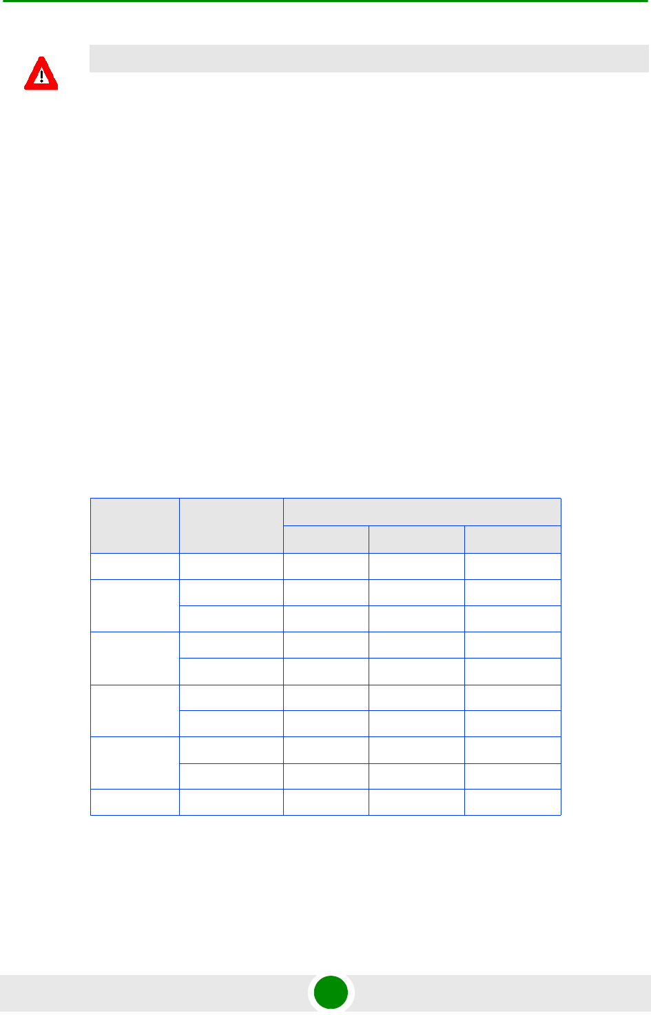
Chapter 4 - Operation and Administration Sector Menu
BreezeMAX Extreme 165 System Manual
4.7.2.2.1.6 Tx Power
The sector’s Tx Power in dBm.
In 3.65 GHz units the actually available range (using 1 dB resolution) is from 18
to 30 dBm. The default is 30 dBm.
The system administrator/installer is responsible for verifying compliance of the
power emitted from the antenna(s) with local regulations and license conditions, if
applicable.
In 4.9 GHz and 5.4 GHz units the HW supports a Tx Power range of 0 to 21 dBm.
However, in units using certain Country Codes the actually available Tx Power
range depends also on the maximum allowed EIRP and Power Spectral Density
according to relevant regulations and on the configured Bandwidth and Antenna
Gain:
CAUTION
If due to either restrictions imposed by local regulations or any other reason you cannot use the
entire frequency band supported by the selected Country Code, you should disable the Random
Channel Selection option (see Section 4.5.4.5.8.1) and use the Usable Frequency option to
define the frequencies manually (see Section 4.7.2.2.2.3)
Table 4-20: Maximum Allowed EIRP, 4.9 GHz Units
Country
Code
Frequency
Range (MHz)
Maximum EIRP (dBm)
5 MHz BW 10 MHz BW 20 MHz BW
Universal 4900-5350 No Limit No Limit No Limit
Canada 4940-4990 53 56 Not Supported
5250-5350 22 25 28
FCC 4940-4990 53 56 Not Supported
5250-5350 22 25 28
Japan 4900-5000 34 34 34
5030-5091 34 34 34
ETSI 5150-5250 17 20 23
5250-5350 17 20 23
5.1 GHz FAA 5090-5150 No Limit No Limit No Limit

Chapter 4 - Operation and Administration Sector Menu
BreezeMAX Extreme 166 System Manual
In 4.9 GHz and 5.4 GHz units, the actual maximum Tx Power is the lowest of the
following values:
The maximum supported by the HW (21 dBm)
Maximum Allowed EIRP (according to the Configured Bandwidth) - the
Configured Antenna Gain.
The default is the highest value that can actually be supported for the relevant
Country Code (using the Gain of the installed Integral Antenna or the default
value of 14 dBi for an External Antenna).
4.7.2.2.2 DFS/DCS (5 GHz units only)
The DFS/DCS menu includes the following options:
Table 4-21: Maximum Allowed EIRP, 5.4 GHz Units
Country
Code
Frequency
Range (MHz)
Maximum EIRP (dBm)
5 MHz BW 10 MHz BW 20 MHz BW
Universal 5470-5950* No Limit No Limit No Limit
Canada 5470-5725 24 27 30
5725-5850 36 36 36
Australia 5470-5600 24 27 30
5650-5725 24 27 30
5725-5850 36 36 36
ETSI 5470-5600 24 27 30
5600-5650 24 27 30
5650-5725 24 27 30
5725-5875 30 33 36
FCC 5470-5725 24 27 30
5725-5850 36 36 36
UK 5725-5795 30 33 36
5815-5850 30 33 36
India 5825-5875 36 36 36
NOTE
For 4.9 GHz units using the FCC Country Code: For compliance with relevant FCC regulations the
maximum Tx Power is in the 4.940-4.990 Ghz sub-band 19 dBm (for all bandwidths/configurations).

Chapter 4 - Operation and Administration Sector Menu
BreezeMAX Extreme 167 System Manual
DFS (if applicable)
DCS
Usable Frequencies (if applicable)
4.7.2.2.2.1 DFS
The DFS parameters submenu is applicable only for units operating in the 5 GHz
bands using a sector frequency for which DFS is required according to the
Country Code being used.
In certain regions there are radar systems operating in the 5 GHz band.
Applicable regulations dictates that wireless access systems operating in these
bands shall not interfere with the operation of the radar systems. This means that
the wireless access system must be able to automatically detect the presence of
radar signals and avoid transmissions on frequencies used by radar systems in its
vicinity.
The Dynamic Frequency Selection (DFS) mechanism is based on monitoring of the
frequency being used and automatic switching to a radar-free frequency upon
detection of radar activity on the current frequency. The test for radar activity is
performed according to the applicable standards (ETSI or FCC), according to the
selected DFS Type.
Before initiating transmission on a new frequency that is not defined as Available
(at start-up after power up or reset none of the frequencies are defined as
Available) the unit performs a Channel Availability Check to ensure that there is
no radar operating on this frequency. During normal operation, the unit
continues monitoring the operating frequency (In-Service Monitoring) to ensure
that there is no radar operating on the frequency. After deciding that a frequency
is Available, it is considered as an Available frequency for a period defined by the
Startup Test Valid Period parameter.
Upon detection of radar activity on the operating frequency, the unit will
automatically stop transmissions on this frequency that will be marked as
Unavailable (Radar Detected) channel. The unit may continue transmissions on
this frequency for a very limited period, allowing it to complete some
transmissions of data and send control and management signals to support the
transition of the served devices to a new channel. The frequency on which radar
was detected will be considered as Unavailable for a period defined by the
configurable Channel Non Occupancy Period parameter. If the Random Channel
Selection parameter (see “Random Channel Selection” on page 102) is set to
Disable, the unit will switch randomly to another frequency in the Usable

Chapter 4 - Operation and Administration Sector Menu
BreezeMAX Extreme 168 System Manual
Frequencies List that is not considered as Unavailable. If the Random Channel
Selection parameter is set to Enable, the unit will switch randomly to another
frequency in the relevant frequency band that is not considered as Unavailable. If
the selected frequency is not marked as Available, the unit will check for radar
activity before initiating transmissions on the new frequency.
If DCS is enabled, it will be activated upon startup or detection of radar activity.
The new channel selected by the DCS mechanism will be tested for presence of
radar activity before initiating transmissions on the new frequency.
In configurations with two sectors, when the DFS Frequencies Management Level
(see “DFS Frequencies Management Level” on page 102) is set to BTS Level, the
Frequencies Status Table of each sector uses also the status information of
relevant frequencies in the frequencies table of the other sector. In these
configurations the DFS mechanism will avoid selection of the channel used by the
other sector.
The parameters that affect the DFS mechanism are defined by the relevant
standards and cannot be configured.
The DFS Menu includes the following options:
Show
Show Frequencies Status Table
4.7.2.2.2.1.1 Show
Select this option to display the following:
DFS Support
DFS Type: According to the DFS type defined in the Country Code (see
“DFS/DCS” on page 101).
Channel Availability Check Time (sec): The minimum time to check a
frequency for the presence of radar activity.
Channel Non Occupancy Period (min): If radar was detected on a certain
frequency, this frequency will be considered as Unavailable for a period
defined by the Channel Non Occupancy Period parameter. During this period
this frequency will not be used by the DFS mechanism.
Startup Test Valid Period (hours): After deciding that a frequency is Available
(no radar was detected by the Channel Availability Check algorithm), it is

Chapter 4 - Operation and Administration Sector Menu
BreezeMAX Extreme 169 System Manual
considered as an Available frequency for a period defined by the Startup Test
Valid Period parameter. During this period the unit may start transmitting on
this frequency without performing a Channel Availability Check.
Radar Detection Threshold (dBm): The Radar Detection Threshold is the
minimum level of received radar signal that must be detected by the algorithm
assuming an Rx Antenna gain of 0 dBi. The higher the EIRP, the higher should
be the Radar Detection Threshold. The threshold depends on the EIRP (Tx
Power + Antenna Gain) of the Sector:
Associated Sector Parameters:
»Bandwidth (MHz): The current Bandwidth of the Sector.
»Tx Power (dBm): The current Tx Power of the Sector.
Associated Antenna Parameters:
»Antenna Gain (dBi): The value configured for the Antenna associated with
the relevant Sector.
4.7.2.2.2.1.2 Show Frequencies Status Table
The DFS Frequencies Status table provides status details for each of the relevant
frequencies (see “Usable Frequencies” on page 174). The details provided for each
entry are:
Frequency (MHz).
Radar Detected Time: The last date and time at which the test results
indicated a presence of radar activity on this frequency, or N/A if the
frequency was not tested since last reset. The frequency is considered as
Unavailable for selection by the DFS mechanism if the elapsed time since the
Detected Time is not higher than Channel Non Occupancy Period.
Last Clear Channel Test: The last date and time at which the test results
indicated that there is no radar activity on this frequency, or N/A if the
frequency was not tested since last reset. The frequency is considered as
Available for selection by the DFS mechanism if the elapsed time since the
Last Clear Channel Test is not higher than Startup Test Valid Period.

Chapter 4 - Operation and Administration Sector Menu
BreezeMAX Extreme 170 System Manual
4.7.2.2.2.2 DCS
The DCS (Dynamic Channel Selection) mechanism is designed to find the most
suitable channel for operation, i.e., the channel with the least interferences.
When the BS is turned on (startup) the DCS is triggered to select one of the best
channels at the current time. The selection is based on Noise and Interference (NI)
level measurements performed in all defined channels by the built-in spectrum
analyzer. DFS (if applicable) will be triggered after the channel selection (for
verification of the channel). A channel that is considered by the DFS mechanism
as Unavailable (see “DFS” on page 167) will not be selected by the DCS
mechanism.
If the Random Channel Selection parameter (see “Random Channel Selection” on
page 102) is set to Disable, the channels to be included in the DCS mechanism
will be those included in the Usable Frequencies List. If the Random Channel
Selection parameter is set to Enable, the unit will select randomly channels from
the relevant frequency band.
In configurations with two sectors, the DCS mechanism will avoid selection of the
channel used by the other sector.
During normal operation (on-going status), spectral efficiency detectors triggers
the DCS mechanism to seek for a new channel when channel conditions cause
performance degradation below a certain level.
Upon channel selection, the DCS is in charge of tracking the channel during
ongoing operation. During channel tracking, the DCS collects the uplink and
downlink RSSI and SNR of MSs served by the BS and calculates the average SNR
according to RSSI ranges. This enables the DCS to track the channel's conditions
according to the actual deployment and conditions, without any need for external
calibration/definitions. The DCS compares the on-going conditions with the
conditions at the initial selection point. If the conditions degraded below a certain
threshold, the channel selection procedure is triggered again.
In Single sector Dual BS Operation Mode, the sector operates using two adjacent
channels. Therefore the selection is based on the statistics gathered from the two
adjacent channels. Also, once a degradation is detected on one of the channels,
instead of stopping the operation in both channels the DCS first verifies if the
other adjacent channel (on the other side of the “good” channel) has better
conditions then the “bad” channel. The verification is performed using the average
NI of the current channel, and the NI measurements of the new channel. If the
channel has better conditions then this channel is selected. This process ensures
that service to MSs served by the “good” channel is not interrupted. If not, then
the operation of both channels is stopped and the new channels selection
mechanism is triggered.

Chapter 4 - Operation and Administration Sector Menu
BreezeMAX Extreme 171 System Manual
The DCS Menu includes the following options:
Show
Update DCS General Parameters
Show DCS Scanning Results
4.7.2.2.2.2.1 Show
Select this option to display the following:
Current DCS Support
Configured DCS Support
The following will be displayed only if Configured DCS Support is set to Enable:
Current NI Channel Measurement Interval (sec)
Configured NI Channel Measurement Interval (sec)
Current SNR Averaging Factor (%)
Configured SNR Averaging Factor (%)
Current SNR Degradation Percentage (%)
Configured SNR Degradation Percentage (%)
Current Channel Tracking Interval (sec)
Configured Channel Tracking Interval (sec)
Current Channel Reference Interval (sec)
Configured Channel Reference Interval (sec)
Current Number of Channels to Scan
Configured Number of Channels to Scan
Current Number of Channels for Selection

Chapter 4 - Operation and Administration Sector Menu
BreezeMAX Extreme 172 System Manual
Configured Number of Channels for Selection
Current Minimum Number of Registered MSs before Starting Tracking
Configured Minimum Number of Registered MSs before Starting Tracking
4.7.2.2.2.2.2 Update DCS General Parameters
The configurable DCS parameters and options are:
DCS Support
NI Channel Measurement Interval (sec)
SNR Averaging Factor (%)
SNR Degradation Percentage (%)
Channel Tracking Interval (sec)
Channel Reference Interval (sec)
Number of Channels to Scan
Number of Channels for Selection
Minimum Number of Registered MSs before Starting Tracking
4.7.2.2.2.2.2.1DCS Support
The DCS Support parameter defines whether the DCS mechanism is enabled or
disabled.
The default is Disable.
The following parameters are applicable only if the configured option for DCS
Support is set to Enable.
4.7.2.2.2.2.2.2NI Channel Measurement Interval (sec)
The NI Channel Measurement Interval defines the time interval for measuring the
Noise and Interference level in a channel from the selected list.
The range is from 10 to 1800 seconds.
The default is 30 seconds.

Chapter 4 - Operation and Administration Sector Menu
BreezeMAX Extreme 173 System Manual
4.7.2.2.2.2.2.3SNR Averaging Factor (%)
The SNR Averaging Factor defines the weight of history (previous average SNR) in
calculating a new average SNR. The calculation is done for the uplink and
downlink of each MS served by the channel.
The range is from 0 to 100 (%)
The default is 20%.
4.7.2.2.2.2.2.4SNR Degradation Percentage (%)
The SNR Degradation Percentage defines the threshold for reaching a decision by
the tracking mechanism that operating conditions of a selected channel have
degraded too much and a new channel should be selected. If the calculated
average SNR for either the uplink or downlink of any of the MSs served by the
channel drops by the defined threshold compared to the reference level calculated
at the time of the channel’s selection, the DCS mechanism will be triggered for
selection of a different channel.
The range is from 0 to 100 (%).
The default is 20 (%).
4.7.2.2.2.2.2.5Channel Tracking Interval (sec)
The Channel Tracking Interval defines the time interval to collect information for
channel tracking.
The range is from 30 to 18000 (seconds).
The default is 60 (seconds).
4.7.2.2.2.2.2.6Channel Reference Interval (sec)
The Channel Reference Interval defines the time interval to collect information
and set the channel's reference conditions.
The range is from 30 to 18000 (seconds).
The default is 60 (seconds).
4.7.2.2.2.2.2.7Number of Channels to Scan
The Number of Channels to Scan parameter is applicable only if Random Channel
Selection (see “Random Channel Selection” on page 102) is enabled. This
parameter defines the number of channels to be randomly selected for inclusion
in the list of channels to be scanned.
The range and default depend on the Country Code and Bandwidth.

Chapter 4 - Operation and Administration Sector Menu
BreezeMAX Extreme 174 System Manual
4.7.2.2.2.2.2.8Number of Channels for Selection
To reduce the probability that the same channel will be selected simultaneously
by two neighboring units (e.g. after a wide-area power outage when several
neighboring units may start-up simultaneously), the channel selection will be
made randomly from a list of the best channels in terms of NI. The Number of
Channels for Selection parameter define number of channels to be included in
this “best channels” list.
The range is from 1 to the number configured for the Number of Channels to Scan
(if Random Channel Selection is enabled) or to the number of channels in the
Usable Frequencies list (if Random Channel Selection is disabled).
The default is 1.
4.7.2.2.2.2.2.9Minimum Number of Registered MSs before Starting Tracking
The Minimum Number of Registered MSs before Starting Tracking defines the
minimum number of CPEs need to be registered before the tracking mechanism is
initiated and the reference point is set.
The range is from 1 to 50.
The default is 1.
4.7.2.2.2.2.3 Show DCS Scanning Results
Select this option to view the measured NI level for each channel included in the
list of channels for scanning. There are two viewing options:
Show DCS Frequencies' NI Table Sorted by Frequency
Show DCS Frequencies' NI Table Sorted by NI
4.7.2.2.2.3 Usable Frequencies
The Usable Frequency option is applicable only if DCS and/or DFS are enabled
and Random Channel Selection (see “Random Channel Selection” on page 102) is
disabled. The Usable Frequencies list includes frequencies to be used for DCS or
DFS mechanism. The subset of usable frequencies list should be defined taking
into account the allowed frequencies according to applicable regulations and the
requirement for uniform spreading.
The Usable Frequency menu includes the following options:
NOTE
For units using a Country Code where DFS is not required by the relevant ETSI/FCC regulations for
certain sub-bands, frequencies in these sub-bands that are included in the Usable Frequencies List
are always considered as Available.
Chapter 4 - Operation and Administration Sector Menu
BreezeMAX Extreme 175 System Manual
Show: To display the current list
Add Frequencies: To add one or several frequencies (in MHz) to the list, where
each entry is in the range from Minimum Frequency+1/2 Bandwidth up to a
maximum of Maximum Frequency-1/2 Bandwidth, using a resolution of 2.5
MHz for a 5 MHz Sector Bandwidth or 5 MHz for a Sector Bandwidth of 10 or
20 MHz. For more details refer to “Frequency” on page 163. Multiple entries
are separated by semi-colon (;).
Delete Frequencies: To delete one or several frequencies (in MHz) from the list.
Multiple entries are separated by semi-colon (;).
Delete Entire List: To clear the list.
4.7.2.2.3 Spectrum Analyzer
The Spectrum Analyzer option enables initiating a spectrum analysis test on
selected frequencies, terminating an active test and viewing the results of the last
test.
Using the parameters defined for the test, the unit scans the selected central
frequencies. The frequencies to be scanned are all frequencies between the
defined Start Frequency and Stop Frequency, using a resolution of 2.5 MHz for a 5
MHz Sector Bandwidth or 5 MHz for a Sector Bandwidth of 10 or 20 MHz. At each
frequency it measures the RSSI for each of the applicable sub-carrier frequencies,
and calculates the median RSSI (for all sub-carriers) and the highest RSSI.
The Spectrum Analyzer menu includes the following options:
Show
Update Spectrum Analyzer General Parameters
Show Spectrum Analyzer Results
4.7.2.2.3.1 Show
Select this option to display the current Spectrum Analyzer parameters
NOTE
The Spectrum Analysis test is a service affecting operation: Services to all units served by the
sector are disconnected for the duration of the test.

Chapter 4 - Operation and Administration Sector Menu
BreezeMAX Extreme 176 System Manual
4.7.2.2.3.2 Update Spectrum Analyzer General Parameters
Select this option to define test parameters and initiate a new test. After properly
completing the definition of test parameters the test is initiated automatically. The
configurable test parameters are:
4.7.2.2.3.2.1 Spectrum Analyzer Support
Select the Enable option to start a new test. The default is Disable.
4.7.2.2.3.2.2 Start Frequency
The lowest frequency (in MHz) in the range of frequencies to be tested. Must be in
the range from Minimum Frequency+1/2 Bandwidth up to a maximum of
Maximum Frequency-1/2 Bandwidth, using a resolution of 2.5 MHz for a 5 MHz
Sector Bandwidth or 5 MHz for a Sector Bandwidth of 10 or 20 MHz. For more
details refer to “Frequency” on page 163.
The default is the lowest frequency that can be supported using these rules.
4.7.2.2.3.2.3 Stop Frequency
The highest frequency (in MHz) in the range of frequencies to be tested. Must meet
the same configuration rules as defined for Start Frequency. In addition, Stop
Frequency cannot be lower than Start Frequency.
The default is the highest frequency that can be supported using these rules.
4.7.2.2.3.2.4 Scanning Time
The test duration in seconds at each of the scanned frequencies.
The available range is from 1 to 3600 seconds, and the default is 60 seconds.
The test will start automatically after configuring the Scanning Time.
4.7.2.2.3.2.5 Step
The resolution of frequencies to be tested, in multiples of 5 MHz (5, 10, 15,...MHz).
4.7.2.2.3.3 Show Spectrum Analyzer Results
Select this option to view the last (if any) test results. There are two viewing
options:
Show results sorted by frequency
Show results sorted by median RSSI
The displayed information for each of the scanned frequencies includes:
Frequency (MHz)

Chapter 4 - Operation and Administration Sector Menu
BreezeMAX Extreme 177 System Manual
Median RSSI (dBm)
Max RSSI (dBm)
Last Scan Date and Time

Chapter 4 - Operation and Administration BS Menu
BreezeMAX Extreme 178 System Manual
4.8 BS M enu
The BS menu enables viewing the current and configured parameters of each BS
and modifying these parameters.
The BS menu includes the following options:
Show Summary: Select this option to view all relevant parameters of the
supported BSs.
Select: Use this option to select the viewing and configuration mode for a
specific BS.
4.8.1 Show Sum mar y
Select this option to view all relevant parameters of the supported BSs. For each of
the supported BSs the following details are displayed:
BS Index
BS ID: A unique identifier of the BS. The BS ID comprises 48 bits displayed in
the format x.x.x.x.x.x (x=0-255).
The BS ID is calculated as follows:
For details on the parameters used for calculating the BS ID refer to:
Operator ID: See “Operator ID” on page 92
Service Zone ID: See “Service Zone ID” on page 93
Cell Number: See “Cell Number” on page 185
Table 4-22: BS ID Calculation
Operator ID Cell ID Sector ID
24 bits 16 bits 8 bits
0-255.0-255.0-255 0-255.0-255 0-3
0-16777215 Service Zone ID(11 bits):
0-2047
Cell Number (5 bits):
0-31
Segment
Number: 0-3

Chapter 4 - Operation and Administration BS Menu
BreezeMAX Extreme 179 System Manual
Segment Number: See “Segment Number” on page 185
BS Name (refer to “BS Name” on page 184)
BS Properties
ASIC HW Version
ASIC SW Version
MAC
Current Segment Number
Configured Segment Number
Current Cell Number
Configured Cell Number
Current Cell Radius (m)
Configured Cell Radius (m)
Current Map Repetition
Configured Map Repetition
Map Compression: Downlink/Uplink (not configurable). Indication that
compression of MAP messages is enabled in both downlink and uplink.
Preamble Index: a read only index of the preamble to use. The Preamble Index
is calculated by:
»For Segment Number 0-3: 3 x (Cell Number) + Segment Number.
»For Segment Number 4: 96 + Cell Number.
Tables 437 & 438 in the IEEE 802.16e standard provide the series to use for
each Preamble Index according to FFT size.
For details on MAC parameters refer to “MAC Parameters” on page 184

Chapter 4 - Operation and Administration BS Menu
BreezeMAX Extreme 180 System Manual
PHY
Current Diversity Mode
Configured Diversity Mode
Current UL Thermal Noise level
Configured UL Thermal Noise level
Current DL HARQ Channels
Configured DL HARQ Channels
Current UL HARQ Channels
Configured UL HARQ Channels
Current HARQ On Management
Configured HARQ On Management
Bandwidth (MHz): The BS Bandwidth depends on the configured Sector
Bandwidth and Operation Mode. For Single Sector Dual BS (with or without
Diversity) Operation Modes the Bandwidth of each BS equals half of the Sector
Bandwidth. For Single Sector Single BS (with or without Diversity) and Dual
Sector Dual BS no Diversity Operation Modes the Bandwidth of each BS
equals the Sector Bandwidth (see “Bandwidth” on page 162).
For details on PHY parameters refer to “PHY Parameters” on page 185
Multi Rate
Uplink Minimum Sub-Channels
Current Uplink Multi Rate Support
Configured Uplink Multi Rate Support
Current Uplink Basic Rate
Configured Uplink Basic Rate

Chapter 4 - Operation and Administration BS Menu
BreezeMAX Extreme 181 System Manual
Current Uplink Fade Margin
Configured Uplink Fade Margin
Current Downlink Multi Rate Support
Configured Downlink Multi Rate Support
Current Downlink Basic Rate
Configured Downlink Basic Rate
Current Downlink Fade Margin
Configured Downlink Fade Margin
For details on Multi Rate parameters refer to “Multi Rate” on page 187
Channelization
Current DL Permutation Base
Configured DL Permutation Base
Current DL Permutation Base Value
Configured DL Permutation Base Value
Current UL Permutation Base
Configured UL Permutation Base
Current UL Permutation Base Value
Configured UL Permutation Base Value
Current Major Group
Configured Major Group
For details on Channelization parameters refer to “Channelization” on page 191
BS Connectivity (applicable only in External ASN-GW Working Mode)

Chapter 4 - Operation and Administration BS Menu
BreezeMAX Extreme 182 System Manual
Current IP Address
Configured IP Address
Current Subnet Mask
Configured Subnet Mask
Current Default Gateway
Configured Default Gateway
MTU Size (Bytes): In current release MTU Size is not configurable and is set to
1700 bytes.
For details on BS Connectivity parameters refer to “Connectivity” on page 193.
ASN-GW Connectivity (applicable only in External ASN-GW Working Mode)
Current IP Address
Configured IP Address
Current VLAN ID
Configured VLAN ID
Current VLAN Priority
Configured VLAN Priority
Current DSCP
Configured DSCP
ASN-GW Operational Status (Up/Down. Presented only if Keep Alive Support
is enabled).
For details on ASN-GW Connectivity parameters refer to “Connectivity” on
page 193.
DSCP QoS Marking (applicable only in External ASN-GW Working Mode)

Chapter 4 - Operation and Administration BS Menu
BreezeMAX Extreme 183 System Manual
ERT DSCP Marking Mode and DSCP Value
NRT DSCP Marking Mode and DSCP Value
BE DSCP Marking Mode and DSCP Value
For details on DSCP QoS Marking parameters refer to “DSCP QoS Marking” on
page 194.
VLAN Priority QoS Marking (applicable only in External ASN-GW Working Mode)
ERT VLAN Priority Marking Mode and VLAN Priority Value
NRT VLAN Priority Marking Mode and VLAN Priority Value
BE VLAN Priority Marking Mode and VLAN Priority Value
For details on VLAN Priority QoS Marking parameters refer to “VLAN Priority QoS
Marking” on page 196.
BS and ASN-GW Keep Alive (applicable only in External ASN-GW Working Mode)
Keep Alive Support
Keep Alive Timer (Seconds)
Keep Alive Interval (Seconds)
Maximum Number Of Keep Alive Failures
If Keep Alive Support is disabled, other Keep alive parameters will not be
presented. For details on BS and ASN-GW Keep Alive parameters refer to “BS and
ASN-GW Keep Alive” on page 198.
4.8.2 Sele ct
Use this option to select the viewing and configuration mode for a specific BS. The
following options are available for the selected BS:
Show
Configuration

Chapter 4 - Operation and Administration BS Menu
BreezeMAX Extreme 184 System Manual
Wireless Counters
4.8.2.1 Show
Select this option to view the relevant parameters of the selected BS. The
displayed information is the same as described in Show Summary (Section 4.8.1)
above.
4.8.2.2 Configuration
Select this option to view (Show option) or modify (Update option) the following
parameters of the BS:
General Parameters
MAC Parameters
PHY Parameters
Multi Rate
Channelization
R6 Interface (applicable only in External ASN-GW Working Mode)
4.8.2.2.1 General Parameters
The General Parameters submenu enables viewing/updating the following
parameter:
4.8.2.2.1.1 BS Name
An optional descriptive parameter. A string of up to 32 printable characters.
The default is null (an empty string).
4.8.2.2.2 MAC Parameters
The MAC Parameters submenu enables viewing/updating the following
parameters:
Segment Number
Cell Number
Cell Radius (m)

Chapter 4 - Operation and Administration BS Menu
BreezeMAX Extreme 185 System Manual
Map Repetition
4.8.2.2.2.1 Segment Number
Each cell can include up to a maximum of 4 sectors. The Segment Number defines
the sector number in the cell.
The range is from 0 to 3.
The default Segment Number is 0.
4.8.2.2.2.2 Cell Number
The Cell Number is the unique identifier of the Cell in the Service Zone.
The maximum number of Cells per Service Zone is 32, with a maximum of 18
Cells with 4 sectors.
The range of the Cell Number parameter is from 0 to 31. For Cells with 4 sectors
the range is from 0 to 17.
The default Cell Number is 0.
4.8.2.2.2.3 Cell Radius (m)
The maximum cell radius in meters. This is the distance from the BTS of the
farthest MS that it can serve.
The range is from 8000 to 40000 meter.
In the current release only Cell Radius values of 8000 and 40000 are supported.
The Cell Radius parameters of both BSs must be set to the same value.
The default Cell Radius is 40000 (m).
4.8.2.2.2.4 Map Repetition
The number of repetitions to use for transmitting DL MAP, UL Map, UCD (Uplink
Channel Descriptor), DCD (Downlink Channel Descriptor), and DIUC (Downlink
Interval Usage Code) messages.
The available values are 1, 2, 4, 6.
The default value is 1.
4.8.2.2.3 PHY Parameters
The PHY Parameters submenu includes the following options:
Show: Select this option to view the relevant PHY parameters of the selected
BS. The displayed information is the same as described in the PHY section of
Show Summary (Section 4.8.1).

Chapter 4 - Operation and Administration BS Menu
BreezeMAX Extreme 186 System Manual
Update: Select this option to update the configured values of the following
parameters:
»Diversity
»UL Thermal Noise Level (dBm)
»DL HARQ Channels
»UL HARQ Channels
»HARQ On Management
4.8.2.2.3.1 Diversity
In the current release the supported diversity modes are:
SISO (Single Input Single Output): No Diversity mode. This is the only mode
that can be used by 1SIS and 2SIS units using No Diversity operation mode. It
cannot be used by units using diversity operation modes.
MIMO Matrix A
MIMO Matrix A&B
MIMO Matrix A for Coverage Gain: In configuration with multiple transmit/receive
antennas, a single data stream is transmitted in parallel over multiple paths. A
mathematical algorithm known as Space Time Codes (STC) is used to encode the
data streams to make them orthogonal to each other. This improves the signal to
noise ratio at the receiver side, resulting in increased range and better throughput
for subscribers that are difficult to reach (e.g. deep indoors).
MIMO Matrix B for Increased Capacity: This flavor of MIMO, also known as
Spatial Multiplexing MIMO (SM-MIMO), sends an independent data stream over
each antenna. Thus, in case signal conditions are good, the data rate is increased
and in excellent conditions may be doubled.
1DIV units that support diversity can be configured to operate in either MIMO
Matrix A or MIMO Matrix A&B modes. When operating in MIMO Matrix A&B mode
the system can use either MIMO Matrix A or MIMO Matrix B. The selection
between Matrix A and Matrix B is performed automatically for each MS according
to link conditions (PER) and supported MS capabilities.
The default for 1DIV units is MIMO Matrix A.

Chapter 4 - Operation and Administration BS Menu
BreezeMAX Extreme 187 System Manual
4.8.2.2.3.2 UL Thermal Noise Level (dBm)
This parameter defines the target noise level to be used for calculating uplink
CINR values that are necessary for various functions such as the power control
mechanism. The BS broadcasts the targeted UL Thermal Noise Level level that is
used by the MSs in open loop power control mode. Increasing the advertised NI
causes the MS to transmit more power to support the same modulation. The NI
value is typically set 6 dB higher than prevailing thermal noise.
The range is from -130 to -100 dBm.
The default is -125 dBm.
4.8.2.2.3.3 DL HARQ Channels
The number of HARQ channels to be used for the WiMAX management connection
in the downlink.
The range is from 8 to 16.
The default is 16.
In 3.65 GHz units, to support operation with BreezeMAX 1000 series CPEs, the
DL HARQ Channels parameters should be set to 10. Otherwise, the value should
not be changed from the default.
4.8.2.2.3.4 UL HARQ Channels
The number of HARQ channels to be used for the WiMAX management connection
in the uplink.
The range is from 8 to 10.
The default is 8.
4.8.2.2.3.5 HARQ On Management
Indicates whether the WiMAX management connection should have HARQ.
The default is Enable.
4.8.2.2.4 Multi Rate
The system employs a multirate algorithm to dynamically adapt the modulation
scheme and Forward Error Correction (FEC) coding to actual link conditions. The
algorithm is managed by the BS taking into account also information received
from the served MSs. Optimal values are calculated separately for the uplink and
CAUTION
A correct value of this parameter is critical for proper performance of the system. Do not change it
from the default value unless advised to modify it by Alvarion’s experts.

Chapter 4 - Operation and Administration BS Menu
BreezeMAX Extreme 188 System Manual
downlink for each MS. MAP messages transmitted to the MSs include information
on the uplink rate that should be used by each MS for its next transmission.
The multirate algorithm optimizes the trade-off between capacity and error rate:
In most deployments, most of the links use high order modulation most of the
time, maximizing capacity. “Bad” links use lower order modulation, maximizing
availability. The algorithm provides independent adaptation per MS, and it is
performed independently for UL and DL, based on link quality information. The
algorithm provides dynamic adaptation - modulation can be changed on a per
burst basis.
The Multi Rate submenu enables viewing/updating the following parameters:
Uplink Multi Rate Support
Uplink Basic Rate
Uplink Fade Margin
Downlink Multi Rate Support
Downlink Basic Rate
Downlink Fade Margin
4.8.2.2.4.1 Uplink Minimum Sub-Channels
The minimum number of sub-channels to be used by the uplink rate adaptation
mechanism. At each rate, the mechanism will move from the highest supported
number of sub-channels (35 for 10 MHz BS bandwidth, 17 for 5 MHz BS
bandwidth) down to the value of this parameter before reaching a decision to
switch to a lower rate. In the other direction, the mechanism will start at this
value and move up to the highest supported number of sub-channels before
reaching a decision to switch to a higher rate.
The range is from 1 to 17 for a 5 MHz BS bandwidth and from 1 to 35 for a 10
MHz BS bandwidth.
The default is 4 sub-channels.
4.8.2.2.4.2 Uplink Multi Rate Support
Defines whether the multi rate algorithm will be used in the uplink. Under normal
operating conditions the Uplink Multi Rate Support should always be enabled.The
option to disable it is provided primarily for testing purposes.
The default is Enable.

Chapter 4 - Operation and Administration BS Menu
BreezeMAX Extreme 189 System Manual
4.8.2.2.4.3 Uplink Basic Rate
When Uplink Multi Rate Support is enabled, the Uplink Basic Rate defines the
lowest rate that can be used by the multi rate algorithm in the uplink. MSs that
cannot communicate with the BS at this rate will not be served. This can be used
to deny service to MSs with very poor link conditions, thus improving the overall
capacity.
When Uplink Multi Rate Support is disabled, this is the fixed rate at which the BS
will communicate with all MSs it can serve.
The available options are:
QPSK-CTC-1/2 REP4
QPSK-CTC-1/2 REP2
QPSK-CTC-1/2
QPSK-CTC-3/4
QAM16-CTC-1/2
QAM16-CTC-3/4
QAM64-CTC-2/3
QAM64-CTC-3/4
QAM64-CTC-5/6
The default rate is QPSK-CTC-1/2.
4.8.2.2.4.4 Uplink Fade Margin
The system uses hard-coded SNR thresholds for rate-adaptation decisions
according to the Diversity Mode. The Uplink Fade Margin is added to the uplink
thresholds, thus enabling to change the actual thresholds used by the uplink
multirate algorithm (“reducing” the sensitivity according to the radio planning).
The range is from 0 to 15 dB.
The default is 2 dB.

Chapter 4 - Operation and Administration BS Menu
BreezeMAX Extreme 190 System Manual
4.8.2.2.4.5 Downlink Multi Rate Support
Defines whether the multi rate algorithm will be used in the downlink. Under
normal operating conditions the Downlink Multi Rate Support should always be
enabled. The option to disable it is provided primarily for testing purposes.
The default is Enable.
4.8.2.2.4.6 Downlink Basic Rate
When Downlink Multi Rate Support is enabled, the Downlink Basic Rate defines
the lowest rate that can be used by the multi rate algorithm in the downlink. MSs
that cannot communicate with the BS at this rate will not be served. This can be
used to deny service to MSs with very poor link conditions, thus improving the
overall capacity.
When Downlink Multi Rate Support is disabled, this is the fixed rate at which the
BS will communicate with all MSs it can serve.
The available options are:
QPSK-CTC-1/2 REP4
QPSK-CTC-1/2 REP2
QPSK-CTC-1/2
QPSK-CTC-3/4
QAM16-CTC-1/2
QAM16-CTC-3/4
QAM64-CTC-2/3
QAM64-CTC-3/4
QAM64-CTC-5/6
The default rate is QPSK-CTC-1/2.
4.8.2.2.4.7 Downlink Fade Margin
The system uses hard-coded SNR thresholds for rate-adaptation decisions
according to the Diversity Mode. The Downlink Fade Margin is added to the
downlink thresholds, thus enabling to change the actual thresholds used by the

Chapter 4 - Operation and Administration BS Menu
BreezeMAX Extreme 191 System Manual
downlink multirate algorithm (“reducing” the sensitivity according to the radio
planning).
The range is from 0 to 15 dB.
The default is 2 dB.
4.8.2.2.5 Channelization
The Channelization submenu enables viewing/updating the following parameters:
DL Permutation Base
DL Permutation Base Value
UL Permutation Base
UL Permutation Base Value
Major Group
4.8.2.2.5.1 DL Permutation Base
The method for configuring/calculating the permutation base used for downlink
sub-channelization.
The available options are Fix, Variable and Rotated.
Fix: The permutation base is defined by the DL Permutation Base Value
parameter (see below).
Variable: The formula is (4*Cell number + Segment number) modulo 32.
Rotated: The formula starts with (4*Cell number + Segment number) modulo
32 (the same as for Variable), incremented by 1 (modulo 32) each frame.
The default is Fix.
In the current release only the Fix option is supported.
4.8.2.2.5.2 DL Permutation Base Value
The value of the downlink permutation base for Fix DL Permutation Base.
The range is from 0 to 31.
The default is 0.

Chapter 4 - Operation and Administration BS Menu
BreezeMAX Extreme 192 System Manual
4.8.2.2.5.3 UL Permutation Base
The method for configuring/calculating the permutation base used for uplink
sub-channelization.
The available options are Fix, Variable and Rotated.
Fix: The permutation base is defined by the UL Permutation Base Value
parameter (see below).
Variable: The permutation base depends on the calculated Preamble Index as
follows:
Rotated: Starts with the same value as calculated for Variable, incremented by
1 (modulo 70) each frame.
The default is Fix.
In the current release only the Fix option is supported.
4.8.2.2.5.4 UL Permutation Base Value
The value of the uplink permutation base for Fix UL Permutation Base.
The range is from 0 to 69.
The default is 0.
4.8.2.2.5.5 Major Group
The subchannelization major groups to be used.
A number from 0 to 63 representing the bit map of major groups 0 to 5. A bit is set
if the applicable major group is selected. The supported combinations depend on
the bandwidth: For BS Bandwidth of 5MHz major group can be 0, 2, 4 or any
combination of 0 and 2 or 0 and 4 or 2 and 4. For BS Bandwidth of 7 or 10MHz
major groups can be 0,1 or 2,3 or 4,5 or 0,1 and 2,3 or 2,3 and 4,5 or 0,1 and 4,5
or 0,1,2,3,4,5.
Table 4-23: Variable UL Permutation Base Calculation
Calculated Preamble Index UL Permutation Base
0-69 = Preamble Index
70-95 = Preamble Index-70
96-111 = Preamble Index-42
112-113 = Preamble Index-112

Chapter 4 - Operation and Administration BS Menu
BreezeMAX Extreme 193 System Manual
The default for BS bandwidth of 7 or 10 MHz is 63 (all major groups selected). The
default for BS bandwidth of 5 MHz is 21 (major groups 0, 2 and 4 selected).
In the current release only the default value (63) is supported.
4.8.2.2.6 R6 Interface
The R6 Interface menu enables viewing/modifying the parameters of the R6
tunnel between the BS and an external ASN-GW. The R6 Interface menu is
applicable only in External ASN-GW Working Mode.
The R6 Parameters menu includes the following sub-menus:
Connectivity
DSCP QoS Marking
VLAN Priority QoS Marking
BS and ASN-GW Keep Alive
4.8.2.2.6.1 Connectivity
The BS Connectivity submenu enables viewing/configuring the following
parameters that affect communication over the R6 tunnel with an external
ASN-GW:
BS IP Address
BS Subnet Mask
BS Default Gateway
MTU Size
ASN-GW IP Address
ASN-GW Default VLAN ID
ASN-GW Default VLAN Priority
ASN-GW DSCP

Chapter 4 - Operation and Administration BS Menu
BreezeMAX Extreme 194 System Manual
4.8.2.2.6.1.1 BS IP Address
The Bearer Interface IP address used for communication with the external
ASN-GW.
4.8.2.2.6.1.2 BS Subnet Mask
The subnet mask of the Bearer Interface IP address.
4.8.2.2.6.1.3 BS Default Gateway
The default gateway IP address for the Bearer Interface. The BS Default Gateway
must be in the subnet of the BS IP Address.
4.8.2.2.6.1.4 MTU Size
The maximum MTU size in Bytes. In the current release this parameter is not
configurable and is set to 1700 bytes.
4.8.2.2.6.1.5 ASN-GW IP Address
The IP address of the external ASN-GW. The ASN-GW IP Address must be in the
subnet of the BS IP Address.
4.8.2.2.6.1.6 ASN-GW Default VLAN ID
The default VLAN ID to be used in communication with the external ASN-GW.
The range is from 1 to 4094 or 4096 for None (untagged).
The default is 4096 (None).
4.8.2.2.6.1.7 ASN-GW Default VLAN Priority
Applicable only if the ASN-GW VLAN ID is other than None (4096). The default
VLAN Priority to be used in communication with the external ASN-GW.
The range is from 0 to 7.
4.8.2.2.6.1.8 ASN-GW DSCP
The DSCP value to be used in communication with the external ASN-GW.
The range is from 0 to 63.
The default is 0.
4.8.2.2.6.2 DSCP QoS Marking
The DSCP QoS Marking submenu enables viewing/updating the following
parameters per QoS type:
4.8.2.2.6.2.1 ERT DSCP Marking Mode
The ERT DSCP Marking Mode define how to handle the outer DSCP marking of
the GRE tunnel for ERT traffic.

Chapter 4 - Operation and Administration BS Menu
BreezeMAX Extreme 195 System Manual
If set to Marking, a configurable DSCP value will be added at uplink direction and
removed at downlink direction together with the GRE tunnel.
If set to Transparent, the value of the inner DSCP will be used also as the outer
DSCP in the uplink direction. No specific action is required at downlink direction
assuming that the inner DSCP is assigned properly.
The following Value parameter is applicable only if ERT DSCP Marking Mode is set
to Marking.
The default is Transparent.
4.8.2.2.6.2.2 ERT DSCP Value
Applicable only if ERT DSCP Marking Mode is set to Marking. The DSCP value to
be applied in the uplink to packets in ERT connections.
A value in the range from 0 to 63.
The default is 0.
4.8.2.2.6.2.3 NRT DSCP Marking Mode
The NRT DSCP Marking Mode define how to handle the outer DSCP marking of
the GRE tunnel for NRT traffic.
If set to Marking, a configurable DSCP value will be added at uplink direction and
removed at downlink direction together with the GRE tunnel.
If set to Transparent, the value of the inner DSCP will be used also as the outer
DSCP in the uplink direction. No specific action is required at downlink direction
assuming that the inner DSCP is assigned properly.
The following Value parameter is applicable only if NRT DSCP Marking Mode is set
to Marking.
The default is Transparent.
4.8.2.2.6.2.4 NRT DSCP Value
Applicable only if NRT DSCP Marking Mode is set to Marking. The DSCP value to
be applied in the uplink to packets in NRT connections.
A value in the range from 0 to 63.
The default is 0.
4.8.2.2.6.2.5 BE DSCP Marking Mode
The BE DSCP Marking Mode define how to handle the outer DSCP marking of the
GRE tunnel for BE traffic.

Chapter 4 - Operation and Administration BS Menu
BreezeMAX Extreme 196 System Manual
If set to Marking, a configurable DSCP value will be added at uplink direction and
removed at downlink direction together with the GRE tunnel.
If set to Transparent, the value of the inner DSCP will be used also as the outer
DSCP in the uplink direction. No specific action is required at downlink direction
assuming that the inner DSCP is assigned properly.
The following Value parameter is applicable only if BE DSCP Marking Mode is set
to Marking.
The default is Transparent.
4.8.2.2.6.2.6 BE DSCP Value
Applicable only if BE DSCP Marking Mode is set to Marking. The DSCP value to be
applied in the uplink to packets in BE connections.
A value in the range from 0 to 63.
The default is 0.
4.8.2.2.6.3 VLAN Priority QoS Marking
The VLAN Priority QoS Marking submenu is not applicable if the ASN-GW Default
VLAN ID (see “ASN-GW Default VLAN ID” on page 194) is set to None (untagged).
The submenu enables viewing/updating the following parameters per QoS type:
4.8.2.2.6.3.1 ERT VLAN Priority Marking Mode
The ERT VLAN Priority Marking Mode define how to handle the outer VLAN
Priority marking of the GRE tunnel for ERT traffic.
If set to Marking, a configurable VLAN Priority value will be added at uplink
direction and removed at downlink direction together with the GRE tunnel.
If set to Transparent, the value of the inner VLAN Priority will be used also as the
outer VLAN parameter in the uplink direction. No specific action is required at
downlink direction assuming that the inner VLAN is assigned properly.
The following Value parameter is applicable only if ERT VLAN Priority Marking
Mode is set to Marking.
The default is Transparent.
4.8.2.2.6.3.2 ERT VLAN Priority Value
Applicable only if ERT VLAN Priority Marking Mode is set to Marking. Enables
configuration of the outer VLAN Priority to be applied in the uplink to packets in
ERT connections.
A value in the range 0 to 7. The default is 0.

Chapter 4 - Operation and Administration BS Menu
BreezeMAX Extreme 197 System Manual
4.8.2.2.6.3.3 NRT VLAN Priority Marking Mode
The NRT VLAN Priority Marking Mode define how to handle the outer VLAN
Priority marking of the GRE tunnel for NRT traffic.
If set to Marking, a configurable VLAN Priority value will be added at uplink
direction and removed at downlink direction together with the GRE tunnel.
If set to Transparent, the value of the inner VLAN Priority will be used also as the
outer VLAN parameter in the uplink direction. No specific action is required at
downlink direction assuming that the inner VLAN is assigned properly.
The following Value parameter is applicable only if NRT VLAN Priority Marking
Mode is set to Marking.
The default is Transparent.
4.8.2.2.6.3.4 NRT VLAN Priority Value
Applicable only if NRT VLAN Priority Marking Mode is set to Marking. Enables
configuration of the outer VLAN Priority to be applied in the uplink to packets in
NRT connections.
A value in the range 0 to 7. The default is 0.
4.8.2.2.6.3.5 BE VLAN Priority Marking Mode
The BE VLAN Priority Marking Mode define how to handle the outer VLAN Priority
marking of the GRE tunnel for BE traffic.
If set to Marking, a configurable VLAN Priority value will be added at uplink
direction and removed at downlink direction together with the GRE tunnel.
If set to Transparent, the value of the inner VLAN Priority will be used also as the
outer VLAN parameter in the uplink direction. No specific action is required at
downlink direction assuming that the inner VLAN is assigned properly.
The following Value parameter is applicable only if BE VLAN Priority Marking
Mode is set to Marking.
The default is Transparent.
4.8.2.2.6.3.6 BE VLAN Priority Value
Applicable only if VLAN Priority Marking Mode is set to Marking. Enables
configuration of the outer VLAN Priority to be applied in the uplink to packets in
BE connections.
A value in the range 0 to 7. The default is 0.

Chapter 4 - Operation and Administration BS Menu
BreezeMAX Extreme 198 System Manual
4.8.2.2.6.4 BS and ASN-GW Keep Alive
The BS and ASN-GW Keep Alive submenu enables viewing/updating the
parameters of the keep-alive mechanism between the BS and the external
ASN-GW:
4.8.2.2.6.4.1 Keep Alive Support
The Keep Alive Support parameter defines whether the keep alive mechanism is
disabled or enabled.
The default is Disable.
If Keep Alive Support is set to Disable the following parameters are not applicable
and are not presented.
4.8.2.2.6.4.2 Keep Alive Timer (Seconds)
The Keep Alive Timer parameter defines the time between PING transmissions to
the ASN-GW.
The range is from 60 to 180 seconds. The default is 60 seconds.
4.8.2.2.6.4.3 Keep Alive Interval (Seconds)
The Keep Alive Interval defines the time to wait for a keep-alive response from the
ASN-GW.
The range is from 1 to 30 seconds. The default is 5 seconds.
4.8.2.2.6.4.4 Maximum Number of Keep Alive Failures
The Maximum Number of Keep Alive Failures defines the maximum number of
keep-alive failures before reaching a decision that the ASN-GW is not reachable.
The range is from 1 to 10. The default is 3.
4.8.2.3 Wireless Counters
The Wireless Counters menu enables showing or resetting the following BS
Wireless counters:
UL Received Packets: The total number of packets received by the BS.
UL Received Bytes: The total number of bytes received by the BS.
UL Discarded Packets: The total number of packets received by the BS that
were discarded.
UL Received CRC Error Packets: The total number of packets with CRC error
received by the BS. The packet error rate is also displayed.

Chapter 4 - Operation and Administration BS Menu
BreezeMAX Extreme 199 System Manual
DL Transmitted Packets: The total number of packets transmitted by the BS.
DL Transmitted Bytes: The total number of bytes transmitted by the BS.
DL Discarded Packets: The total number of packets intended for transmission
by the BS that were discarded before transmission.

Chapter 4 - Operation and Administration Radio Channel Menu
BreezeMAX Extreme 200 System Manual
4.9 Ra dio Channel Me nu
Each BS has two Radio Channels. In configurations using Operation Mode with
no Diversity, only one Radio Channel is used. In configurations using Operation
Mode with Diversity, two Radio Channels are used.
The Radio Channel menu includes the following options:
Show Summary: Select this option to view all relevant parameters of the
available Radio Channels.
Select: Use this option to select the viewing and configuration mode for a
specific Radio Channel.
4.9.1 Show Sum mar y
Select this option to view all relevant parameters of the available Radio
Channel(s). For each of the Radio Channels the following details are displayed:
Radio Channel ID (1 and 2 for BS1, 3 and 4 for BS2. In configurations with no
Diversity Radio Channels 2 and 4 are not applicable).
General Parameters
Admin Status (for details see “Admin Status” on page 201)
Operational Status (Up/Down)
Frequency (MHz): Calculated based on the Operation Mode and Frequency
Settings for relevant Sector(s). For the Dual Sector Dual BS no Diversity and
Single Sector Single BS with or without Diversity Operation Modes the
Channel(s) Frequency equals the Sector’s Frequency. For Single Sector Dual
BS with or without Diversity Operation Modes the Frequency of BS1
Channel(s) is the Sector Frequency-1/2 Sector Bandwidth, and the Frequency
of BS2 Channel(s) is the Sector Frequency+1/2 Sector Bandwidth.
4.9.2 Sele ct
Use this option to select the viewing and configuration mode for a specific Radio
Channel. The following options are available for the selected Radio Channel:

Chapter 4 - Operation and Administration Radio Channel Menu
BreezeMAX Extreme 201 System Manual
Show
Update
4.9.2.1 Show
Select this option to view the relevant parameters of the selected Radio Channel.
The displayed information is the same as described in Show Summary
(Section 4.9.1) above.
4.9.2.2 Update
Select this option to modify the Admin Status parameter of the Radio Channel:
4.9.2.2.0.1 Admin Status
The Admin Status parameter is used to control the administrative status of the
channel.
For proper operation the Admin Status of all applicable channels should be
enabled.
The default Admin status is Disable.

Chapter 4 - Operation and Administration Antenna Menu
BreezeMAX Extreme 202 System Manual
4.10 Antenna M enu
According to the capabilities supported by the hardware and (if applicable) the
selected Operation Mode, the unit can use one or two antennas. For Integral
Antennas the parameters are read only and cannot be modified. For External
Antennas the parameters are configurable.
The Antenna menu enables viewing the configured parameters of each Antenna
and modifying the parameters of External Antenna(s).
The Antenna menu includes the following options:
Show Summary: Select this option to view all relevant parameters of the
Antenna(s).
Select: Use this option to select the viewing and configuration mode for a
specific Antenna.
4.10.1 Show Sum mar y
Select this option to view all relevant parameters of the configured Antenna(s). For
each of the available Antennas the following details are displayed:
Antenna ID
Current Antenna Gain (dBi)
Configured Antenna Gain (dBi)
Beam Width (degrees)
Antenna Polarization
Antenna Type: Integral or External according to the unit’s type.
Refer to Section 4.10.2.2 for details on these parameters.
NOTE
In configurations that supports a single Antenna only Antenna 1 is available.
Chapter 4 - Operation and Administration Antenna Menu
BreezeMAX Extreme 203 System Manual
4.10.2 Selec t
Use this option to select the viewing and configuration mode for a specific
Antenna. The following options are available for the selected Antenna:
4.10.2.1 Show
Select this option to view the relevant parameters of the selected Antenna. The
displayed information is the same as described in Show Summary (Section 4.10.1)
above.
4.10.2.2 Update
This option is applicable only for external Antennas. Select this option to
configure/modify the following parameters of the selected Antenna:
Antenna Gain (dBi)
Beam Width (degrees)
Antenna Polarization
4.10.2.2.1 Antenna Gain (dBi)
The gain of the antenna in dBi.
The range is from 0 to 40 dBi.
The defaults is 14 dBi.
4.10.2.2.2 Beam Width (degrees)
The antenna’s beamwidth in degrees.
Available values are 60, 90, 120 and 360 degrees.
NOTE
For a Dual Slant antenna only Antenna 1 should be configured. The read-only configuration of
Antenna 2 will be copied from the configuration of Antenna 1.
NOTE
For units using a Country Code with limitation on the maximum allowed EIRP, the configuration
range for Antenna Gain depends on the currently configured values for Tx Power and Bandwidth.
For more details refer to “Tx Power” on page 165.
For such units using two antennas per sector, the gain of both antennas must be set to the same
value.

Chapter 4 - Operation and Administration Antenna Menu
BreezeMAX Extreme 204 System Manual
The default is 0 (a different value must be configured).
4.10.2.2.3 Antenna Polarization
The polarization of the antenna.
Available options are Vertical, Horizontal, Dual Slant and Omni. The Omni option
is available only if the configured Beam Width is 360 degrees. No other option is
supported for a beamwidth of 360 degrees.

Chapter 4 - Operation and Administration GPS Menu
BreezeMAX Extreme 205 System Manual
4.11 GPS M enu
The GPS menu enables viewing the status and general GPS information and the
current and configured values of the GPS parameters. It also enables updating the
configurable GPS parameters.
The GPS menu includes the following options:
4.11.1 Show Sum mar y
Select the Show Summary option to view the following details:
Chain parameters
Chain Number
Current GPS Type
Configured GPS Type
Hold Over Passed Timeout (min)
Stop TX after Hold over Timeout
Time Zone Offset From UTC (hours)
Daylight Saving
Start Date
Stop Date
Advance Hour Factor
For details refer to “Chain Parameters” on page 207. The Start Date, Stop Date
and Advance Hour Factor parameters are applicable only if Daylight Saving is set
to Enable.
Clock Parameters
Clock Mode
External 1 PPS Clock

Chapter 4 - Operation and Administration GPS Menu
BreezeMAX Extreme 206 System Manual
External 10 MHz Clock
For details refer to “Clock Parameters” on page 209.
GPS Info Parameters
The GPS Info Parameters include read-only information received from the GPS
receiver (when available).
Number Of Received Satellites: The number of satellites received by the GPS
receiver. For proper operation at least four satellites should be received.
Longitude: The longitude as calculated by the GPS receiver. The format is
<xxx.yyy A>, where xxx is the longitude in degrees, yyy is in minutes, and A is
either N (North) or S (South).
Latitude: The latitude as calculated by the GPS receiver. The format is
<xxx.yyy A>, where xxx is the longitude in degrees, yyy is in minutes, and B is
either E (East) or W (West).
Altitude (m): The altitude in meters as calculated by the GPS receiver.
Calculated Local Date and Time: The local date and time (using 24 hours
clock) as calculated using the data received from the GPS receiver and taking
into account the configured Time Zone Offset From UTC and Daylight Saving
parameters.
Navigation Processor SW Version: The number and date of the GPS Navigation
Processor SW Version.
Signal Processor SW Version: The number and date of the GPS Signal
Processor SW Version.
GPS HW Version: The GPS HW Version.
GPS Status
External 1PPS: The status of External 1PPS clock (OK or Failed).
External 10MHz: The status of External 10MHz clock (OK or Failed).

Chapter 4 - Operation and Administration GPS Menu
BreezeMAX Extreme 207 System Manual
4 Satellites And More: Applicable only for Trimble GPS, indicating whether 4
(the minimum required for initial synchronization) or more satellites are
received by the GPS receiver (OK or Failed).
2 Satellites And More: Applicable only for Trimble GPS, indicating whether 2
(the minimum number required for maintaining synchronization) or more
satellites are received by the GPS receiver (OK or Failed).
GPS 1PPS Communication: Applicable only for Trimble GPS, indicating the
status of communication with the GPS receiver (OK or Failed).
Hold Over: Indicating whether the device has entered into Hold Over state
(None or Started).
Hold Over T/O: Indicating whether Hold Over Timeout has passed (None or
Passed).
BS transmit: Indicating whether the BSs are transmitting or not
(OK/Stopped).
4.11.2 Configurat ion
The GPS Configuration menu enables managing the following:
4.11.2.1 Chain Parameters
Chaining of co-located BTSs is required to fully support intra-site
synchronization. When two or more BTSs are chained, all clocks are sent from the
Master BTS to the Slave BTSs. The Chain menu includes parameters that should
be shared by all BTSs belonging to the same chain.
The Chain menu includes the following:
4.11.2.1.1 Chain Number
The Chain Number is used as a unique identifier of a chain. All BTSs belonging to
the same chain should be configured with the same Chain Number. The Chain
Number can be used by a central management system to guarantee that certain
limitations are met: in each chain, one, and only one BTS should be defined as
Master.
The range is from 1 to 1500.
The default is 0, indicating that a Chain Number is not configured yet. A valid
Chain Number must be configured, and this number must be unique in the
managed network to properly support chaining.

Chapter 4 - Operation and Administration GPS Menu
BreezeMAX Extreme 208 System Manual
4.11.2.1.2 GPS Type
The GPS Type defines the GPS receiver.
The available options are None and Trimble.
The default is Trimble.
4.11.2.1.3 Stop Tx After Hold Over Timeout
For initial synchronization, a minimum of four satellites must be received properly
(meeting certain criteria). Upon losing the 1PPS clock from the GPS, or if the
received clock is not considered accurate enough because the number of received
satellites dropped below the minimum (two satellites), the local 1PPS clock will be
generated using the internal 10MHz clock. After a certain time (defined by the
Hold Over Passed Timeout parameter described below), it is assumed that due to
clock drifts there might be interferences among sectors belonging to the BTS and
sectors belonging to neighboring BTSs. If the Stop Tx After Hold Over Timeout
parameter is set to Enable, the BTS will stop transmitting after this timeout
(unless the number of properly received satellites has increased again to four or
more), to prevent interferences to the sectors belonging to other BTSs. If it is set to
Disable, transmissions will continue indefinitely, at the expense of potential
interferences to sectors belonging to other BTSs.
The default is Disable (Hold Over indefinitely).
4.11.2.1.4 Hold Over Passed Timeout (Min)
This parameter defines the Hold Over timeout, after which there might be
interferences to other sectors. When the Stop Tx After Hold Over Timeout is
enabled, transmissions will stop after this timeout. When the Stop Tx After Hold
Over Timeout is disabled, this timeout is used to generate a trap indicating that
there might be interferences to neighboring sectors.
The range is from 0 to 2880 (minutes).
The default is 30 (minutes).
4.11.2.1.5 Time Zone Offset From UTC
This is the offset of the local time from UTC (Coordinated Universal Time).
The range is from -12:00 up to +13:00 in 30 minutes resolution. The format must
be either -XX:YY or +XX:YY where YY is either 00 or 30.
The default is +00:00.
NOTE
If GPS Type is set to Trimble the unit will not start transmitting until initial synchronization (at least 4
properly received satellites) is achieved.

Chapter 4 - Operation and Administration GPS Menu
BreezeMAX Extreme 209 System Manual
4.11.2.1.6 Daylight Saving
The Daylight Saving parameter is used to enable or disable the daylight saving
feature using the following Start Date, End Date and Advance Hour Factor
parameters.
The default is Disable
4.11.2.1.7 Start Date
When Daylight Saving is enabled, this parameter defines the date for starting the
daylight saving feature. At the beginning of this date (midnight at the beginning of
this date), the clock will be advanced by the amount of hours specified by the
Daylight Saving Advance Factor (see below).
Use the format dd:mm to define the date and month at which to start activating
the Daylight Saving feature.
4.11.2.1.8 End Date
When Daylight Saving is enabled, this parameter defines the date for ending the
daylight saving feature (at “Daylight Saving Advance Factor” hours after midnight
at the end of this date).
Use the format dd:mm to define the date and month at which to end activating the
Daylight Saving feature.
4.11.2.1.9 Advance Hour Factor
This parameter enables configuring the amount of time by which the clock should
be advanced during the daylight saving period.
The range is from 0 to 4:45 (hours) in steps of 15 minutes.
4.11.2.2 Clock Parameters
The configurable Clock parameter is Clock Mode, The Show option for Clock
Parameters displays also the sources for the main clocks in the system according
to the Clock Mode.
The Clock Parameters are:
Clock Mode
External 1PPS Clock (read-only)
External 10MHz Clock (read-only)

Chapter 4 - Operation and Administration GPS Menu
BreezeMAX Extreme 210 System Manual
4.11.2.2.1 Clock Mode
The Clock Mode parameters defines the location of the unit in the chain. The
available options are:
Master
Slave#1 (the first Slave unit in the chain, connected to the Master unit)
Slave#2 (the second Slave unit in the chain, connected to Slave#1)
Slave#3 (the third Slave unit in the chain, connected to Slave#2)
Slave#4 (the fourth Slave unit in the chain, connected to Slave#3)
The default is Master.
Under normal conditions, the clocks are supplied by the Master unit to the Slave
units. If Slave#1 will detect that it does not receive clocks for a certain period of
time, it will assume that the Master unit has failed and will start using its internal
10 MHz clock, supplying the clocks also to the other slave units (if exist). Slave#2
will wait for a longer period of time before assuming that both the Master and
Slave#1 have failed, and so on.
The functionality and operation mode of the main clocks is:
4.11.2.2.2 External 1PPS Clock (read-only)
The 1PPS (Pulse Per Second) clock is used to determine the air-frame start time.
Assuming that all systems use the same air-frame size and DL/UL Ratio, then,
when the 1PPS clock is received from a GPS system, this mechanism ensures
inter-site and intra-site synchronization among all sectors, preventing cross
interference and saturation problems. When using the internal 1PPS clock
(derived from the 10MHz clock source), only intra-site synchronization among
sectors can be achieved.
For a Master unit the default External 1PPS Clock is Disable (use internal 1PPS
clock source derived from either the built-in GPS receiver or from the 10MHz
clock).
For Slave units the default External 1PPS Clock is Enable (derived from the
previous unit in the chain).

Chapter 4 - Operation and Administration GPS Menu
BreezeMAX Extreme 211 System Manual
4.11.2.2.3 External 10MHz Clock (read-only)
The 10MHz clock source is used for generation of all main clocking signals in the
system, including the internal 1PPS clock when GPS Type is set to None or when
the GPS receiver does not function properly.
For a Master unit the default External 10MHz Clock is Disable (use internal clock
source).
For Slave units the default External 10MHz Clock is Disable (derived from the
previous unit in the chain).

Chapter 4 - Operation and Administration MS Menu
BreezeMAX Extreme 212 System Manual
4.12 MS Menu
The MS menu enables viewing general details on MSs that exist in the database. It
also enables resetting (de-registering) a connected MS. In Embedded Distributed
ASN-GW Local Authentication working mode it also enables adding/deleting MSs
to/from the database.
The MS menu includes the following options:
Show Summary
Show Concise Summary
Show Summary by BS
Show Concise Summary by BS
Select By MAC
Add
4.12.1 Show Sum mar y
Select this option to view summary information and main details for all connected
and pre-configured MSs.
For each MS, the following information is displayed:
MS MAC Address
MS IP Address: The MS Management IP address
BS ID: The BS to which the MS is connected (1 or 2), or 0 if the MS is not
connected to any BS.

Chapter 4 - Operation and Administration MS Menu
BreezeMAX Extreme 213 System Manual
Operational Status (the current state in the network entry process):
»Service Defined Not In Use
»Radio Up
»Authorized
»In Service
UL RSSI (dBm)
UL CINR (dB)
In addition, the following summary information is provided:
Total Number of MSs: The total number of SUs in the database (including
connected and pre-configured MSs)
Total Number of MSs Connected to BS1
Total Number of MSs Connected to BS2
4.12.2 Show Concise Summ ary
Select this option to view the summary information for all MSs:
Total Number of MSs: The total number of SUs in the database (including
connected and pre-configured MSs)
Total Number of MSs Connected to BS1
Total Number of MSs Connected to BS2
4.12.3 Show Sum mar y by BS
Select this option to view the total number of MSs connected to a specific BS as
well as main details on these MSs, as described in Section 4.12.1. You will be
prompted to select the required BS ID.

Chapter 4 - Operation and Administration MS Menu
BreezeMAX Extreme 214 System Manual
4.12.4 Show Concise Summ ary by BS
Select this option to view the total number of MSs connected to a specific BS. You
will be prompted to select the required BS ID.
4.12.5 Sele ct By MAC
Select this option to select a specific MS by its MAC address. The menu for the
selected MS includes the following options:
Show
Show Allocated IP Addresses
Counters
Continuous Display of CINR/RSSI
De-Register MS
Delete
4.12.5.1 Show
Select this option to view the general details of the selected MS:
MS IP Address:
BS ID
Operational Status
4.12.5.2 Show Allocated IP Addresses
Select this option to view the IP addresses allocated to the MS. For each allocated
IP address the Connectivity Type (Data, Voice, or Management) will be indicated.
4.12.5.3 Counters
The Counter menu includes the following options:
General Counters
Rate Counters

Chapter 4 - Operation and Administration MS Menu
BreezeMAX Extreme 215 System Manual
4.12.5.3.1 General Counters
Select this option to view or reset the general counters of the MS:
UL RSSI (dBm)
UL CINR (dB)
UL Rate
UL Total Transmitted Bytes
UL Total Transmitted Packets
UL Total Lost Packets
UL Total CRC Error Packets
UL Total Transmitted Bursts
UL HARQ ACK Bursts
UL HARQ NACK Bursts
UL HARQ Dropped Bursts
DL RSSI (dBm)
DL CINR (dB)
DL Rate
DL Total Transmitted Bytes
DL Total Transmitted Packets
DL Total Lost Packets
DL Total Transmitted Bursts
DL HARQ ACK Bursts
DL HARQ NACK Bursts

Chapter 4 - Operation and Administration MS Menu
BreezeMAX Extreme 216 System Manual
DL HARQ Dropped Bursts
4.12.5.3.2 Rate Counters
Select this option to view or reset the rate counters of the MS:
DL rate counters - SISO/MIMO A: Displaying for each of the possible rates the
total number of Acknowledged (ACK) and Not Acknowledged (NACK) bursts
transmitted using SISO or MIMO A.
DL rate counters - MIMO B: Displaying for each of the possible rates the total
number of Acknowledged (ACK) and Not Acknowledged (NACK) bursts
transmitted using SISO or MIMO B.
UL rate counters: Displaying for each of the possible rates the total number of
Acknowledged (ACK) and Not Acknowledged (NACK) bursts received.
4.12.5.4 Continuous Display of CINR/RSSI
Select this option for a continuously updated display of DL and UL CINR and
RSSI. Click the Esc key to stop the display.
4.12.5.5 De-Register MS
Select this option to force de-registration (link disconnection) of the MS by sending
a De-Registration message from the BTS to the MS. The MS will re-initiate
network entry.
4.12.5.6 Delete
Select this option to delete the selected MS from the database. Applicable only in
Embedded Distributed ASN-GW Local Authentication working mode.
4.12.6 Add
Select this option to Add an MS to the database. You will be prompted to enter the
MAC address. Applicable only in Embedded Distributed ASN-GW Local
Authentication working mode.

Chapter 4 - Operation and Administration Parameters Summary
BreezeMAX Extreme 217 System Manual
4.13 Pa ramete rs Summ a ry
Table 4-24: BTS Parameters Summary
Parameter Range Default Run-Time
Updated
BTS - Configuration - General Parameter
BTS Number 1-999999 0 No
BTS Name Up to 32 printable characters Null Yes
BTS Location Up to 64 printable characters Null Yes
BTS Contact Up to 64 printable characters Null Yes
BTS - Configuration - Working Mode
BTS Working Mode Embedded Distributed ASN-GW
Authenticated
Embedded Distributed ASN-GW
Local Authentication
External ASN-GW (not supported in
current release)
Embedded
Distributed ASN-GW
Authenticated
No
BTS - Configuration - Connectivity
IP Address IP address 1.1.1.23 No
Subnet Mask subnet mask 255.255.255.0 No
Default Gateway IP address 0.0.0.0 (none) No
VLAN ID 1-4094 or 4096 for No VLAN 4096 No
VLAN Priority 0-7 No
BTS - Configuration - Authorized Managers
Authorized Manager IP
Address
IP address Yes
Authorized Manager Read
Community
Up to 32 printable characters, case
sensitive
public Yes
Authorized Manager Write
Community
Up to 32 printable characters, case
sensitive
private Yes
Traps Distribution Enabled Disable
Enable
Enable Yes
BTS - Configuration - Radio Parameters

Chapter 4 - Operation and Administration Parameters Summary
BreezeMAX Extreme 218 System Manual
Operator ID x.y.z, where x, y, z are in the range 0 to
255
0.0.0 (must be
changed)
No
Operator Name Up to 32 printable characters Null Yes
Service Zone ID 0-2047 0 (must be changed) No
Service Zone Name Up to 32 printable characters Null Yes
Operation Mode 1SIS units:
Single Sector Single BS no Diversity
Single Sector Dual BS no Diversity
(available only if 20 MHz license is
installed)
1DIV units:
Single Sector Single BS with Diversity
Single Sector Dual BS with Diversity
(available only if 20 MHz license is
installed)
2SIS units: Dual Sector Dual BS no
Diversity
According to supplied
hardware:
1SIS units: Single
Sector Single BS no
Diversity
1DIV units: Single
Sector Single BS with
Diversity
2SIS units: Dual
Sector Dual BS no
Diversity
No
DL/UL Ratio In current release only DL = 60% : UL =
40% is supported
DL = 60% : UL = 40% No
Country Code Available options depend on radio band
supported by the unit
Universal No
Frequencies Management
Level (if DFS supported by
Country Code)
Sector Level
BTS Level
Sector Level No
Random Channel Selection
(5 GHz units only)
Enable
Disable
Disable No
BTS - Unit Control - Change Password
Administrator Password 1 to 16 printable characters, case
sensitive
admin Yes
Installer Password 1 to 16 printable characters, case
sensitive
installer Yes
Table 4-24: BTS Parameters Summary
Parameter Range Default Run-Time
Updated

Chapter 4 - Operation and Administration Parameters Summary
BreezeMAX Extreme 219 System Manual
Monitor Password 1 to 16 printable characters, case
sensitive
monitor Yes
BTS - Unit Control - SW Version Control - Load to Shadow
TFTP Server IP Address IP address Yes
File Name up to 80 printable characters Yes
BTS-Unit Control-Configuration File Control-Upload Configuration File-Activate Upload
Operation
File Type Full Configuration
Services (SP & MSF) File (not
applicable in External ASN-GW
working mode)
Yes
TFTP Server IP Address IP address Yes
File Path and Name up to 80 printable characters Full Configuration:
backup.res
Services:
profiles_srvc.res
Yes
BTS-Unit Control-Configuration File Control-Download Configuration File-Activate
Download Operation
File Type Full Configuration
Services (SP & MSF) File (not
applicable in External ASN-GW
working mode)
RFU Heads File
Country Codes File
Yes
TFTP Server IP Address IP address Yes
File Path and Name up to 80 printable characters Full Configuration:
backup.res
Services:
profiles_srvc.res
Yes
BTS-Unit Control-License Files Control-Download License File to Unit
TFTP Server IP Address IP address Yes
File Path and Name up to 80 printable characters Yes
BTS-Unit Control-Monitor Inactivity Timeout
Table 4-24: BTS Parameters Summary
Parameter Range Default Run-Time
Updated

Chapter 4 - Operation and Administration Parameters Summary
BreezeMAX Extreme 220 System Manual
Monitor Inactivity Timeout
(min)
0-60 minutes. 0 means no timeout. 10 minutes Yes
BTS-Fault Management-Trap Configuration-Distribution Enabled-Update
Trap ID Trap ID Yes
Trap Distribution Enabled Disable
Enable
Enable Yes
BTS-Fault Management-Trap Configuration-Alarm Severity-Update
Trap ID Alarm Trap ID Yes
Trap Severity Indeterminate
Critical
Major
Minor
Warning
Depends on trap Yes
BTS-Fault Management-Trap Configuration-Suppression Interval-Update
Trap ID Trap ID Yes
Trap Suppression Interval
(sec)
0-86400 seconds. 0 means no
suppression.
0Yes
BTS-Fault Management-Event Log Selection Criteria
Minimum Severity All
Clear
Indeterminate
Critical
Major
Minor
Warning
All Yes
Last Days 1-31 days 3 Yes
Table 4-24: BTS Parameters Summary
Parameter Range Default Run-Time
Updated

Chapter 4 - Operation and Administration Parameters Summary
BreezeMAX Extreme 221 System Manual
Managed Object Type All
BTS
ASN GW
Sector
BS
Radio Channel
GPS
Antenna
MS
All Yes
Specific Event Category All
Alarm
State Change
Configuration Change
System Event
All Yes
ASN-GW - AAA - Configuration - AAA Client
Retry Interval (sec) 1-30 (seconds) 5 (seconds) Yes
Maximum Number of Retries 1-10 3 Yes
Keep Alive Timeout (sec) 60-180 (seconds) 60 (seconds) Yes
ASN-GW - AAA - Configuration - Authentication Server
Server Address IP address Null Yes
Server Alias 1-32 printable characters Null Yes
Shared Secret 1 to 16 printable characters, case
sensitive
Null Yes
UDP Port Number 1-65535 1812 Yes
ASN-GW - AAA - Configuration - Accounting Server
Server Address IP address Null Yes
Server Alias 1-32 printable characters Null Yes
Table 4-24: BTS Parameters Summary
Parameter Range Default Run-Time
Updated

Chapter 4 - Operation and Administration Parameters Summary
BreezeMAX Extreme 222 System Manual
Shared Secret 1 to 16 printable characters, case
sensitive
Null Yes
UDP Port Number 1-65535 1813 Yes
ASN-GW - Services - MSs Services
MS MAC Address MAC address (must exist in database) Yes
Admin Status Enable
Disable
Yes
Multiple Service Flow Name A Multiple Service Flow Name that exists
in database.
Yes
Service Profile Name A Service Profile Name that exists in
database.
Yes
ASN-GW - Services - Service Profiles
Service Profile Name 1-32 printable characters Yes
Service Profile Type Management
Data
PPPoE
VoIP.
Reliable Video
Yes
ASN-GW - Services - Service Profiles - Selected Service Profile - QoS Profiles
Uplink QoS Type BE
NRT
ERT
Yes
Uplink CP 0-7
BE: only 0 is supported.
NRT: 1-2
ERT: 3-7
Yes
Uplink CIR 32-54000 Kbps 32 Yes
Table 4-24: BTS Parameters Summary
Parameter Range Default Run-Time
Updated

Chapter 4 - Operation and Administration Parameters Summary
BreezeMAX Extreme 223 System Manual
Uplink MIR BE & NRT: 32-54000 Kbps
ERT: Depends on CP.
(cannot be lower than Uplink CIR)
32 Yes
Downlink QoS Type BE
NRT
ERT
Yes
Downlink CP 0-7
BE: only 0 is supported.
NRT: 1-2.
ERT: 3-7
Yes
Downlink CIR 32-54000 Kbps 32 Yes
Downlink MIR 32-54000 Kbps (cannot be lower than
Downlink CIR)
32 Yes
ASN-GW - Services - Multiple Service Flows
Multiple Service Flow Name 1-32 printable characters Yes
Service Group Name A Service Group Name that exists in
database.
Yes
Service Operation Mode Bridge
Router
Yes
ASN-GW - Services - Multiple Service Flows - Selected Multiple Service Flow - Service
Rules
Service Interface Name A Service Interface Name that exists in
database.
Yes
ASN-GW - Services - Multiple Service Flows - Selected Multiple Service Flow - Service
Rules - Selected Service Rule - Classifiers
Uplink Classifier Type Any
DSCP
VLAN ID
VLAN Priority
Yes
Table 4-24: BTS Parameters Summary
Parameter Range Default Run-Time
Updated

Chapter 4 - Operation and Administration Parameters Summary
BreezeMAX Extreme 224 System Manual
Uplink Classifier Parameter 1 DSCP: 0-63
VLAN ID: 1-4094
VLAN Priority: 0-7
Yes
Uplink Classifier Parameter 2 DSCP: 0-63
VLAN Priority: 0-7
(cannot be lower than Uplink Classifier
Parameter 1)
Yes
Downlink Classifier Type Any
DSCP
VLAN ID
VLAN Priority
Yes
Downlink Classifier
Parameter 1
DSCP: 0-63
VLAN ID: 1-4094
VLAN Priority: 0-7
Yes
Downlink Classifier
Parameter 2
DSCP: 0-63
VLAN Priority: 0-7
(cannot be lower than Downlink Classifier
Parameter 1)
Yes
ASN-GW - Services - Service Groups
Service Group Name 1-32 printable characters Yes
DHCP Type None
Transparent
Forward with Option 82
Relay with Option 82
Server
Yes
Nomadic Mode Enable
Disable
Disable Yes
Table 4-24: BTS Parameters Summary
Parameter Range Default Run-Time
Updated

Chapter 4 - Operation and Administration Parameters Summary
BreezeMAX Extreme 225 System Manual
Attribute 31 None
CPE MAC Address
CPE Fully Qualified Domain Name
For DHCP Relay/Forward with Option 82
modes the available options are None,
CPE MAC Address and the option
selected for the Option 82 Sub Type 2
parameter.
CPE MAC Address Yes
Attribute 32 None
BTS MAC Address
GIADDR
Service Interface VLAN
Management IP Address
BS ID
BTS Name
Free Text
For DHCP Relay/Forward with Option 82
modes the available options are None,
BS ID and the option selected for the
Option 82 Sub Type 1 parameter
Yes
Attribute 32 Free Text 1-32 printable characters Yes
Interface IP Address IP address Yes
Interface Subnet Mask Yes
DefaultGateway IP address 0.0.0.0 Yes
VLAN ID 0-4094 or 4096 for None 0 Yes
VLAN Priority 0-7 Yes
DHCP Server Specific Parameters
DHCP Pool IP Address IP address Yes
DHCP Pool Subnet Mask Subnet Mask Yes
DNS 1 IP Address IP address Yes
Table 4-24: BTS Parameters Summary
Parameter Range Default Run-Time
Updated

Chapter 4 - Operation and Administration Parameters Summary
BreezeMAX Extreme 226 System Manual
DNS 2 IP Address IP address Yes
DHCP IP Address IP address Yes
DHCP Lease Time 0 to 4294967295 seconds. 0 means
infinite (no lease time).
65535 Yes
DHCP Management Server Up to 100 printable characters Yes
Option 82 Sub Type 1 None
BTS MAC Address
GIADDR
Service Interface VLAN
Management IP Address
BS ID
BTS Name
Free Text
None Yes
Option 82 Sub Type 1 Free
Text
1-32 printable characters Yes
Option 82 Sub Type 2 None
CPE MAC Address
CPE Fully Qualified Domain Name
CPE MAC Address Yes
DHCP Relay with Option 82 Specific Parameters
GI IP Address IP address Yes
DHCP IP Address IP address Yes
Subnet Mask Subnet mask Yes
ASN-GW - Services - Service Interfaces
Service Interface Name 1-32 printable characters Yes
Forwarding Rule Name A Forwarding Rule Name that exists in
database.
Yes
CS Type Ethernet CS
IP CS
IP CS Yes
Table 4-24: BTS Parameters Summary
Parameter Range Default Run-Time
Updated

Chapter 4 - Operation and Administration Parameters Summary
BreezeMAX Extreme 227 System Manual
VLAN Interface Enable
Disable
Enable Yes
VLAN Transparency Enable
Disable
Disable Yes
VLAN ID 1-4094 or null for No VLAN Yes
VLAN Priority Marking Enable
Disable
Disable Yes
VLAN Priority 0-7 Yes
VLAN List Up to 16 VLAN IDs (1-4094) separated
by commas or empty for All (including
none)
empty Yes
Inner DSCP Marking Enable
Disable
Yes
Inner DSCP 0-63 Yes
ASN-GW - Services - Forwarding Rules
Forwarding Rule Name 1-32 printable characters Yes
Relay Mode Enable
Disable
Yes
Unknown Address
Forwarding Mode
Forward
Discard
Yes
QoS Type BE
NRT
Yes
CP 0-2
BE: only 0 is supported.
NRT: 1-2.
Yes
CIR 32-54000 Kbps Yes
MIR 32-54000 Kbps (cannot be lower than
CIR)
Yes
Table 4-24: BTS Parameters Summary
Parameter Range Default Run-Time
Updated

Chapter 4 - Operation and Administration Parameters Summary
BreezeMAX Extreme 228 System Manual
ASN-GW - Services - MSs Default Services-Add
MS MAC Address MAC address (must exist in database) Yes
Service Number 1-3 Yes
Admin Status Enable
Disable
Yes
Data CS Type Ethernet CS Data
IP CS Data
Yes
ASN-GW - Services - MSs Services
ASN-GW - MAC Access Lists
MAC Address (single
addresses list)
MAC address Yes
Prefix Address (ranges list) MAC address Yes
Prefix Mask (ranges list) MAC mask Yes
Allow/Deny Allow
Deny
Yes
Priority (ranges list) 1-255 Yes
Default Accesss Allow
Deny
Allow Yes
Maximum MAC Addresses
Learned
0-1024. 0 means no limit up to the
maximum of 1024.
0Yes
Sector - General Parameter
Sector Name Up to 32 printable characters null Yes
Sector Location Up to 64 printable characters Null Yes
Sector Heading 0-359 (degrees) 0 Yes
Table 4-24: BTS Parameters Summary
Parameter Range Default Run-Time
Updated

Chapter 4 - Operation and Administration Parameters Summary
BreezeMAX Extreme 229 System Manual
Bandwidth 5 MHz
7 MHz (3.65 GHz units only)
10 MHz
14 MHz (3.65 GHz units only)
20 MHz
14 and 20 MHz are applicable only for
units using Single Sector Dual BS with or
without Diversity Operation Mode,
provided a 20 MHz license is installed.
10 MHz No
Frequency Depends on supported frequency band,
configured Bandwidth.and Country Code.
Depends on
supported frequency
band, configured
Bandwidth.and
Country Code.
No
Tx Power Depends on unit type. In 5 GHz units
depend also on Country Code and
Antenna Gain.
Depends on unit type.
In 5 GHz units
depend also on
Country Code and
Antenna Gain.
No
Sector - DFS / DCS - DCS (5 GHz units only)
DCS Support Enable
Disable
Disable No
NI Channel Measurement
Interval (sec)
10 to 1800 (seconds) 30 No
SNR Averaging Factor (%) 0 to 100 (%) 20 No
SNR Degradation Percentage
(%)
0 to 100 (%) 20 No
Channel Tracking Interval
(sec)
30 to 18000 (seconds) 60 No
Channel Reference Interval
(sec)
30 to 18000 (seconds) 60 No
Number of Channels to Scan Depends on Country Code Name and
bandwidth
Depends on Country
Code Name and
bandwidth
No
Table 4-24: BTS Parameters Summary
Parameter Range Default Run-Time
Updated

Chapter 4 - Operation and Administration Parameters Summary
BreezeMAX Extreme 230 System Manual
Number of Channels for
Selection
1 to the number configured for the
Number of Channels to Scan (if Random
Channel Selection is enabled) or to the
number of channels in the Usable
Frequencies list (if Random Channel
Selection is disabled).
1No
Minimum Number of
Registered MSs before
Starting Tracking
1 to 50 1 No
Sector - Spectrum Analyzer
Spectrum Analyzer Support Enable
Disable
Disable Yes
Start Frequency Depends on Country Code and
bandwidth
The lowest available
frequency
Yes
Stop Frequency Depends on Country Code and
bandwidth
The highest available
frequency
Yes
Scanning Time 1 to 3600 (seconds) 60 Yes
Step Multiples of 5 MHz (5, 10, 15..) 5 Yes
BS - General Parameters
BS Name Up to 32 printable characters Null Yes
BS - MAC
Segment Number 0-3 0 No
Cell Number 0-31. For cells with 4 sectors the range is
0-17.
0No
Cell Radius 8000-40000 (meter)
In current release only 8000 and 40000
are supported
40000 No
Map Repetition 1, 2, 4, 6. 1 No
BS - PHY
Table 4-24: BTS Parameters Summary
Parameter Range Default Run-Time
Updated

Chapter 4 - Operation and Administration Parameters Summary
BreezeMAX Extreme 231 System Manual
Diversity No Diversity operation mode: SISO
Diversity operation mode:
MIMO Matrix A
MIMO Matrix A & B (only if MIMO
Matrix B license is installed)
No Diversity
operation mode:
SISO
Diversity operation
mode: MIMO Matrix A
No
UL Thermal Noise Level -130 to -100 (dBm) -125 No
DL HARQ Channels 8-16 8 No
UL HARQ Channels 8-10 16 No
HARQ On Management Enable
Disable
Enable No
BS - Multi Rate
Uplink Minimum
Sub-Channels
5 MHz BW: 1-17
10 MHz BW: 1-35
4Yes
Uplink Multi Rate Support Enable
Disable
Enable No
Uplink Basic Rate QPSK-CTC-1/2 REP4
QPSK-CTC-1/2 REP2
QPSK-CTC-1/2
QPSK-CTC-3/4
QAM16-CTC-1/2
QAM16-CTC-3/4
QAM64-CTC-2/3
QAM64-CTC-3/4
QAM64-CTC-5/6
QPSK-CTC-1/2 No
Uplink Fade Margin 0-15 (dB) 2 (dB) No
Downlink Multi Rate Support Enable
Disable
Enable No
Table 4-24: BTS Parameters Summary
Parameter Range Default Run-Time
Updated

Chapter 4 - Operation and Administration Parameters Summary
BreezeMAX Extreme 232 System Manual
Downlink Basic Rate QPSK-CTC-1/2 REP4
QPSK-CTC-1/2 REP2
QPSK-CTC-1/2
QPSK-CTC-3/4
QAM16-CTC-1/2
QAM16-CTC-3/4
QAM64-CTC-2/3
QAM64-CTC-3/4
QAM64-CTC-5/6
QPSK-CTC-1/2 No
Downlink Fade Margin 0-15 (dB) 2 (dB) No
BS - Channelization
DL Permutation Base Fix
Variable
Rotated
In current release only Fix is supported
Fix No
DL Permutation Base Value 0-31 0 No
UL Permutation Base Fix
Variable
Rotated
In current release only Fix is supported
Fix No
UL Permutation Base Value 0-69 0 No
Major Group 0-63. In current release only the default is
supported (63 for BS BW 7 or 10 MHz, 21
for BS BW 5 MHz).)
63 for BS bandwidth
of 7 or 10 MHz.
21 for BS bandwidth
of 5 MHz.
No
BS - R6 Interface - Connectivity
BS IP Address IP address No
Table 4-24: BTS Parameters Summary
Parameter Range Default Run-Time
Updated

Chapter 4 - Operation and Administration Parameters Summary
BreezeMAX Extreme 233 System Manual
BS Subnet Mask subnet mask No
BS Default Gateway IP address No
ASN-GW IP Address IP address No
ASN-GW Subnet Mask subnet mask No
ASN-GW Default Gateway IP address No
ASN-GW Default VLAN ID 1-4094 or 4096 for No VLAN 4096 No
ASN-GW Default VLAN
Priority
0-7 No
ASN-GW DSCP 0-63 0 No
BS - R6 Interface - DSCP QoS Marking
ERT DSCP Marking Mode Transparent
Marking
Transparent Yes
ERT DSCP Value 0-63 0 Yes
NRT DSCP Marking Mode Transparent
Marking
Transparent Yes
NRT DSCP Value 0-63 0 Yes
BE DSCP Marking Mode Transparent
Marking
Transparent Yes
BE DSCP Value 0-63 0 Yes
BS - R6 Interface - VLAN Priority QoS Marking
ERT VLAN Priority Marking
Mode
Transparent
Marking
Transparent Yes
ERT VLAN Priority Value 0-7 0 Yes
NRT VLAN Priority Marking
Mode
Transparent
Marking
Transparent Yes
NRT VLAN Priority Value 0-7 0 Yes
BE VLAN Priority Marking
Mode
Transparent
Marking
Transparent Yes
BE VLAN Priority Value 0-7 0 Yes
Table 4-24: BTS Parameters Summary
Parameter Range Default Run-Time
Updated

Chapter 4 - Operation and Administration Parameters Summary
BreezeMAX Extreme 234 System Manual
BS - R6 Interface - BS and ASN-GW Keep Alive
Keep Alive Support Enable
Disable
Disable Yes
Keep Alive Timer (sec) 60-180 seconds 60 Yes
Keep Alive Interval (sec) 1-30 seconds 5 Yes
Maximum Number of Keep
Alive Failures
1-10 3 Yes
Radio Channel - General
Admin Status Enable
Disable
Disable Yes
Antenna (configurable only for external antenna)
Antenna Gain 0-40 dBi 14 No
Beam Width 60, 90, 120 or 360 degrees Yes
Antenna Polarization Vertical, Horizontal, Dual Slant or Omni Yes
GPS - Chain Parameters
Chain Number 1 - 1500 0 (means not defined
yet-must be defined)
No
GPS Type None
Trimble
Trimble Yes
Hold Over Passed Timeout 0 - 2880 (minutes) 30 (minutes) No
Stop Tx After Hold Over
Timeout
Disable
Enable
Disable No
Time Zone Offset From UTC -12:00 to +13:00 in steps of 30 minutes +00:00 No
Daylight Saving Disable
Enable
Disable No
Daylight Saving Start Date dd.mm Yes
Daylight Saving End Date dd.mm Yes
Daylight Saving Advance
Factor
0 to 4:45 hours in 15 minutes steps +00:00 Yes
GPS - Clock Parameters
Table 4-24: BTS Parameters Summary
Parameter Range Default Run-Time
Updated

Chapter 4 - Operation and Administration Parameters Summary
BreezeMAX Extreme 235 System Manual
Clock Mode Master
Slave#1
Slave#2
Slave#3
Slave#4
Master No
MS - Add (applicable only in Embedded Distributed ASN-GW Local Authentication working mode)
Select MS MAC MAC address Yes
Table 4-24: BTS Parameters Summary
Parameter Range Default Run-Time
Updated

Glossa ry

Glossary
BreezeMAX Extreme 237 System Manual
AAA Authentication, Authorization, and Accounting (pronounced "triple a."). A system (or
several systems) that controls what resources users have access to, and keeps
track of the activity of users over the network.
AAS Adaptive Antenna System, also called Advanced Antenna System, is a technology to
enable the network operators to increase the wireless network capacity. In addition,
adaptive antenna systems offer the potential of increased spectrum efficiency,
extended range of coverage and higher rate of frequency reuse. Adaptive antenna
systems consist of multiple antenna elements at the transmitting and/or receiving
side of the communication link, whose signals are processed adaptively in order to
exploit the spatial dimension of the mobile radio channel. Depending on whether the
processing is performed at the transmitter, receiver, or both ends of the
communication link, the adaptive antenna technique is defined as multiple-input
single-output (MISO), single-input multiple-output (SIMO), or multiple-input
multiple-output (MIMO).
ASCII American Standard Code for Information Interchange. A code for representing
English characters as numbers, with each letter assigned a number from 0 to 127.
ASN Access Service Network. An ASN is defined as a complete set of network functions
needed to provide radio access to a WiMAX subscriber. An ASN is comprised of
network elements such as one or more Base Stations (BS) and one or more ASN
gateways (ASN-GW). An ASN may be shared by more than one Connectivity
Service Network (CSN).
ASN-GW Access Service Network Gateway. The ASN-GW is a network entity that acts as a
gateway between the ASN and CSN. The ASN functions hosted in an ASN-GW may
be viewed as consisting of two groups - the decision point (DP) that provides control
functionality and enforcement point (EP) that provides bearer transport.
AU Access Unit
AWG An electronics industry acronym for American Wire Gauge. AWG is a measure of the
thickness of copper, aluminum and other wiring.
BTS Base Transceiver Station. A wireless network element that provides the radio
interface of the network. The BTS comprises the radio transmission and reception
devices, and also manages the signal processing related to the air interface.
BW Bandwidth
CINR Carrier-to-Interference plus Noise Ratio (expressed in dB)
CIR Committed Information Rate. The rate (in bits per second) at which a network
guarantees to transfer information under normal conditions, averaged over a
minimum increment of time.
CLI Command Line Interface. A user interface that accepts typed commands to instruct
the managed device on the task to perform.
CPU Central Processing Unit.
CS Convergence Sublayer. Particular protocols that are responsible for gathering and
formatting higher layer information so it can be processed by the lower layers.

Glossary
BreezeMAX Extreme 238 System Manual
CSMA/CD Carrier Sense Multiple Access with Collision Detection. Media-access mechanisms
wherein devices ready to transmit data first check the channel for a carrier. If no
carrier is sensed for a specific period of time, a device can transmit. If two devices
transmit at once, a collision occurs and is detected by all colliding devices. This
collision subsequently delays retransmissions from those devices for some random
length of time. Ethernet and IEEE 802.3 use CSMA/CD access.
CSN Connectivity Service Network. A CSN is defined as a set of network functions that
provide IP connectivity services to WiMAX subscribers and all the IP core network
functions. A CSN is comprised of network elements such as routers, proxy/servers,
user databases, and inter-working gateway devices.
CTC Convolutional Turbo Code is a type of turbo codes with some of the convolutional
schemes used. For its high-performance error correction nature, CTC is the iterative
decoding scheme of choice as evidenced by their wide adoption in standards bodies.
DCD Downlink Channel Descriptor.
DHCP Dynamic Host Configuration Protocol. A protocol for dynamically assigning IP
addresses from a pre-defined list to nodes on a network. Using DHCP to manage IP
addresses simplifies client configuration and efficiently utilizes IP addresses.
DL Down Link
DSCP Differentiated Service Code Point, AKA DiffServ: An alternate use for the ToS byte in
IP packets. Six bits of this byte are being reallocated for use as the DSCP field
where each DSCP specifies a particular per-hop behavior that is applied to the
packet.
DNS Domain Naming System. A system that stores information about hostnames and
domain names. DNS provides an IP address for each hostname, and lists the e-mail
exchange servers accepting e-mail addresses for each domain.
DSL Digital Subscriber Line. A technology that exploits unused frequencies on copper
telephone lines to transmit traffic typically at multi-megabit speeds. DSL can allow
voice and high-speed data to be sent simultaneously over the same line. Because
the service is 'always available,' end-users don't need to dial in or wait for call set-up.
EAP Extensible Authentication Protocol, A protocol used between a user station and an
authenticator or authentication server. It acts as a transport for authentication
methods or types. It, in turn may be encapsulated in other protocols, such as 802.1x
and RADIUS. EAP is defined by RFC 2284.
EDT Electrical Down-Tilt
EIRP Equavalent Isotropic Radiated Power. The apparent power transmitted towards the
receiver, if it is assumed that the signal is radiated equally in all directions. The EIRP
is equal to the power (in dBm) at the antenna port, plus the power gained from the
directivity of the antenna (in dBi).
EMC Electro-Magnetic Compatibility. The capability of equipment or systems to be used in
their intended environment within designed efficiency levels without causing or
receiving degradation due to unintentional EMI (Electro Magnetic Interference). EMC
generally encompasses all of the electromagnetic disciplines.

Glossary
BreezeMAX Extreme 239 System Manual
ETS European Telecommunications Standard
ETSI European Telecommunications Standards Institute. A non-profit organization
producing voluntary telecommunications standards used throughout Europe, some
of which have been adopted by the EC as the technical base for Directives or
Regulations.
GPS Global Positioning System. A system that uses satellites, receivers and software to
allow users to determine their precise geographic position.
GRE General Routing Encapsulation. A method or technique of adding an IP standard
header and trailer to a message that does not follow IP protocols. The encapsulated
message is sent over a public network while received messages are stripped of the
wrapper and processed. This permits non-standard data and totally encrypted
messages to use the Internet. The technology is an important element in Virtual
Private Network (VPN) offerings.
HP High Power.
IEEE Institute of Electrical and Electronics Engineers. IEEE (pronounced I-triple-E) is an
organization of engineers, scientists, and students. The IEEE is best known for
developing standards for the computer and electronics industry. In particular, the
IEEE 802 standards for local-area networks are widely followed.
IEEE 802.16 Also known as WIMAX. A group of broadband wireless communications standards
for metropolitan area networks (MANs) developed by a working group of the IEEE.
IEEE 802.16e 802.16e, also known as 802.16-2005, is an IEEE standard addressing mobility of
wireless broadband (WiMax). IEEE 802.16e is sometimes called Mobile WiMAX,
after the WiMAX forum for interoperability. 802.16e, based on an existing WiMAX
standard 802.16a, adds WiMAX mobility in the 2-to-6 GHz-licensed bands. 802.16e
allows for fixed wireless and mobile Non Line of Sight (NLOS) applications primarily
by enhancing the OFDMA (Orthogonal Frequency Division Multiple Access).
IEEE 802.1p A QoS method - A three-bit value that can be placed inside an 802.1Q frame tag.
IEEE 802.1q The IEEE 802.1q standard defines the operation of VLAN Bridges that permit the
definition, operation and administration of Virtual LAN topologies within a Bridged
LAN infrastructure. The 802.1q specification establishes a standard method for
inserting VLAN membership information into Ethernet frames. A tag field containing
VLAN (and/or 802.1p priority) information can be inserted into an Ethernet frame,
carrying VLAN membership information.
IEEE 802.3 A Local Area Network protocol suite commonly known as Ethernet. Ethernet uses
Carrier Sense Multiple Access bus with Collision Detection CSMA/CD. This method
allows users to share the network cable. However, only one station can use the
cable at a time. A variety of physical medium dependent protocols are supported.
IF Intermediate Frequency. Radio communications systems modulate a carrier
frequency with a baseband signal in order to achieve radio transmission. In many
cases, the carrier is not modulated directly. Instead, a lower IF signal is modulated
and processed. At a later circuit stage, the IF signal is converted up to the
transmission frequency band.

Glossary
BreezeMAX Extreme 240 System Manual
IGMP Internet Group Membership Protocol) is protocol used by IP hosts to report their host
group memberships to any immediately neighboring multicast routers.
The use of IP multicasting in TCP/IP networks is defined as a TCP/IP standard in
RFC 1112. In addition to defining address and host extensions for how IP hosts
support multicasting, this RFC also defines the IGMP version 1. Version 2 of IGMP is
defined in RFC 2236. Both versions of IGMP provide a protocol to exchange and
update information about host membership in specific multicast groups.
IP Internet Protocol. The standard that defines how data is transmitted over the
Internet. IP bundles data, including e-mail, faxes, voice calls and messages, and
other types, into "packets", in order to transmit it over public and private networks.
LED Light Emitting Diode.
MAC Media Access Control. The lower of the two sub-layers of the data link layer defined
by the IEEE. The MAC sub-layer handles access to shared media, such as whether
token passing or contention will be used.
MAC Address Standardized data link layer address that is required for every port or device that
connects to a LAN. Other devices in the network use these addresses to locate
specific ports in the network and to create and update routing tables and data
structures. MAC addresses are 6bytes long and are controlled by the IEEE.
MDT Mechanical Down-Tilt
MIB Management Information Base. A database of objects that can be monitored by a
network management system. SNMP uses standardized MIB formats that allow any
SNMP tools to monitor any device defined by a MIB.
MIMO Multiple Input, Multiple Output. A technique for faster wireless communication.
MIMO allows for the use of multiple transmitter and receiver antennas to increase
throughput and range.
MIP Mobile IP. A protocol used to provide IP mobility to IPv4-based nodes, defined in
RFC-2002.
MIR Maximum Information Rate. Specifies the maximum rate of information that can be
available to a user. The MIR is used by the traffic policing mechanism to prevent
users from sending excess traffic to the network.
MTU Maximum Transmission Unit. This is the greatest amount of data that can be
transferred in one physical frame on the network. If a packet that has a smaller MTU
than the packet's frame length is sent, fragmentation will occur. For TCP, MTU can
range from 68 to 1500 bytes. Larger MTUs provide for lower overhead (fewer
headers).
MS Mobile Station. The equipment used by the end user to access the WiMAX network.
NAP Network Access Provider. A NAP is a business entity that provides WiMAX radio
access infrastructure to one or more Network Service Providers (NSPs). An NAP
implements this infrastructure using one or more ASNs.

Glossary
BreezeMAX Extreme 241 System Manual
NMS Network Management System. A system responsible for managing at least part of a
network. An NMS is generally a reasonably powerful and well-equipped computer,
such as an engineering workstation. NMSs communicate with agents to help keep
track of network statistics and resources.
NSP Network Service Provider. An NSP is a business entity that provides IP connectivity
and WiMAX services to WiMAX subscribers compliant with the established service
level agreement. The NSP concept is an extension of the Internet service provider
(ISP) concept, providing network services beyond Internet access. To provide these
services, an NSP establishes contractual agreements with one or more NAPs. An
NSP may also establish roaming agreements with other NSPs and contractual
agreements with third-party application providers (e.g. ASP, ISP) for the delivery of
WiMAX services to subscribers. From a WiMAX subscriber standpoint, an NSP may
be classified as a home or visited NSP.
OFDM Orthogonal Frequency Division Multiplexing: A method for multiplexing signals,
which divides the available bandwidth into a series of frequencies known as tones.
Orthogonal tones do not interfere with each other when the peak of one tone
corresponds with the null. The rapid switching, frequency-hopping technique is
intended to allow more robust data service.
OFDMA Orthogonal Frequency Division Multiple Access. It’s a logical extension of OFDM
and a modulation/multiple access technique. OFDMA divides a signal into
sub-channels (i.e. groups of carriers), with each sub-channel (or several
sub-channels) being allocated to a different subscriber.
PER Packet Error Rate. In a digital transmission, PER is the percentage of packets with
errors divided by the total number of packets that have been transmitted, received or
processed over a given time period.
PHY PHYsical Layer. The physical, or lowest, layer of the OSI Network Model. In a
wireless network, the PHY defines parameters such as data rates, modulation
method, signaling parameters, transmitter/receiver synchronization, etc. Within an
actual radio implementation, the PHY corresponds to the radio front end and
baseband signal processing sections.
PS Power Supply
QoS Quality of Service. Measure of performance for a transmission system that reflects
its transmission quality and service availability.
QPSK Quadrature Phase Shift Keying. A data transfer technique used in coaxial cable
networks that sends data using modulating signals. Four different phases represent
data, with each signal's information determined by the signal before it. For example,
if a phase stays the same from one signal to the other, the information has not
changed.
RADIUS Remote Authentication Dial-In User Service, an authentication and accounting
system used by many Internet Service Providers (ISPs). When you connect to the
system you must enter your username and password. This information is passed to
a RADIUS server, which checks that the information is correct, and then authorizes
access to the system.

Glossary
BreezeMAX Extreme 242 System Manual
RF Radio frequency. An AC signal of high enough frequency to be used for wireless
communications.
RFC Request For Comments. The name of the result and the process for creating a
standard on the Internet. New standards are proposed and published on the Internet,
as a Request For Comments. The proposal is reviewed by the Internet Engineering
Task Force.
RoHS Restriction of the use of certain Hazardous Substances in electrical and electronic
equipment, reference EC Directive 2002/95/EC of 27 January 2003.
RSSI Received Signal Strength Indicator. A signal or circuit that indicates the strength of
the incoming (received) signal in a receiver.
Rx Receive
SNMP Simple Network Management Protocol. A network management protocol that
provides a means to monitor and control network devices, and to manage
configurations, statistics collection, performance, and security. SNMP works by
sending messages, called protocol data units (PDUs), to different parts of a network.
SNMP-compliant devices, called agents, store data about themselves in
Management Information Bases (MIBs) and return this data to the SNMP
requesters.
SSH Secure Shell is a protocol for secure remote login and other secure network services
over an insecure network.
TCP Transmission Control Protocol. Connection-oriented transport layer protocol that
provides reliable full-duplex data transmission. TCP is the part of the TCP/IP suite of
protocols that is responsible for forming data connections between nodes that are
reliable, as opposed to IP, which is connectionless and unreliable.
TFTP Trivial File Transfer Protocol. Simplified version of FTP that allows files to be
transferred from one computer to another over a network, usually without the use of
client authentication.
Tx Transmit
UAbbreviation for "Unit" or standard height measurement which defines the vertical
height for plug-in modules in the 19” construction system. One U equals 44.5 mm.
UCD Uplink Channel Descriptor.
UDP User Datagram Protocol. Connectionless transport layer protocol in the TCP/IP
protocol stack. UDP is a simple protocol that exchanges datagrams without
acknowledgments or guaranteed delivery, requiring that error processing and
retransmission be handled by other protocols. UDP is defined in RFC 768.
UL Up Link
VLAN Virtual Local Area Network. A group of devices on one or more LANs that are
configured with the same VLAN ID so that they can communicate as if they were
attached to the same wire, when in fact they are located on a number of different
LAN segments. Used also to create separation between different user groups.

Glossary
BreezeMAX Extreme 243 System Manual
VoIP Voice over Internet Protocol. Provides an advanced digital communications network
that bypasses the traditional public switched telephone system and uses the Internet
to transmit voice communication. VoIP enables people to use the Internet as the
transmission medium for telephone calls by sending voice data in packets using IP
rather than by traditional circuit switched transmissions of the PSTN.
WCS Wireless Communications Service is defined by the Federal Communications
Commission as radio communications that may provide fixed, mobile, radio location,
or satellite communication services to individuals and businesses within their
assigned spectrum block and geographical area. The WCS is in the 2.3 GHz band
from 2,305 to 2,320 MHz and 2,345 to 2,360 MHz..
WEEE Waste Electronic and Electrical Equipment. The purpose of Directive 2002/96/EC on
waste electrical and electronic equipment (WEEE) is, as a first priority, the
prevention of waste electrical and electronic equipment (WEEE), and in addition, the
reuse, recycling and other forms of recovery of such wastes so as to reduce the
disposal of waste. It also seeks to improve the environmental performance of all
operators involved in the life cycle of electrical and electronic equipment, e.g.
producers, distributors and consumers and in particular those operators directly
involved in the treatment of waste electrical and electronic equipment.
Wi-Fi Wi-Fi (short for wireless fidelity and pronounced 'why-fye') is a term for certain types
of wireless local area network that use specifications in the IEEE 802.11 family. The
term Wi-Fi was created by an organization called the Wi-Fi Alliance, which oversees
tests that certify product interoperability.
WiMAX WiMAX is an acronym that stands for Worldwide Interoperability for Microwave
Access. WiMAX is a standards-based technology enabling the delivery of last mile
wireless broadband access as an alternative to cable and DSL. WiMAX provides
fixed, nomadic, portable, and mobile wireless broadband connectivity without the
need for direct line-of-sight to a base station.
XML Extensible Markup Language. Language used for defining a set of markers, called
tags, that define the function and hierarchical relationships of the parts of a
document or data set. It is a flexible way to create common information formats and
share both the format and the data, most commonly on the web. It generally similar
to HTML and helps share information in a consistent way. XML is "extensible"
because, unlike HTML, the markup symbols are unlimited and self-defining.