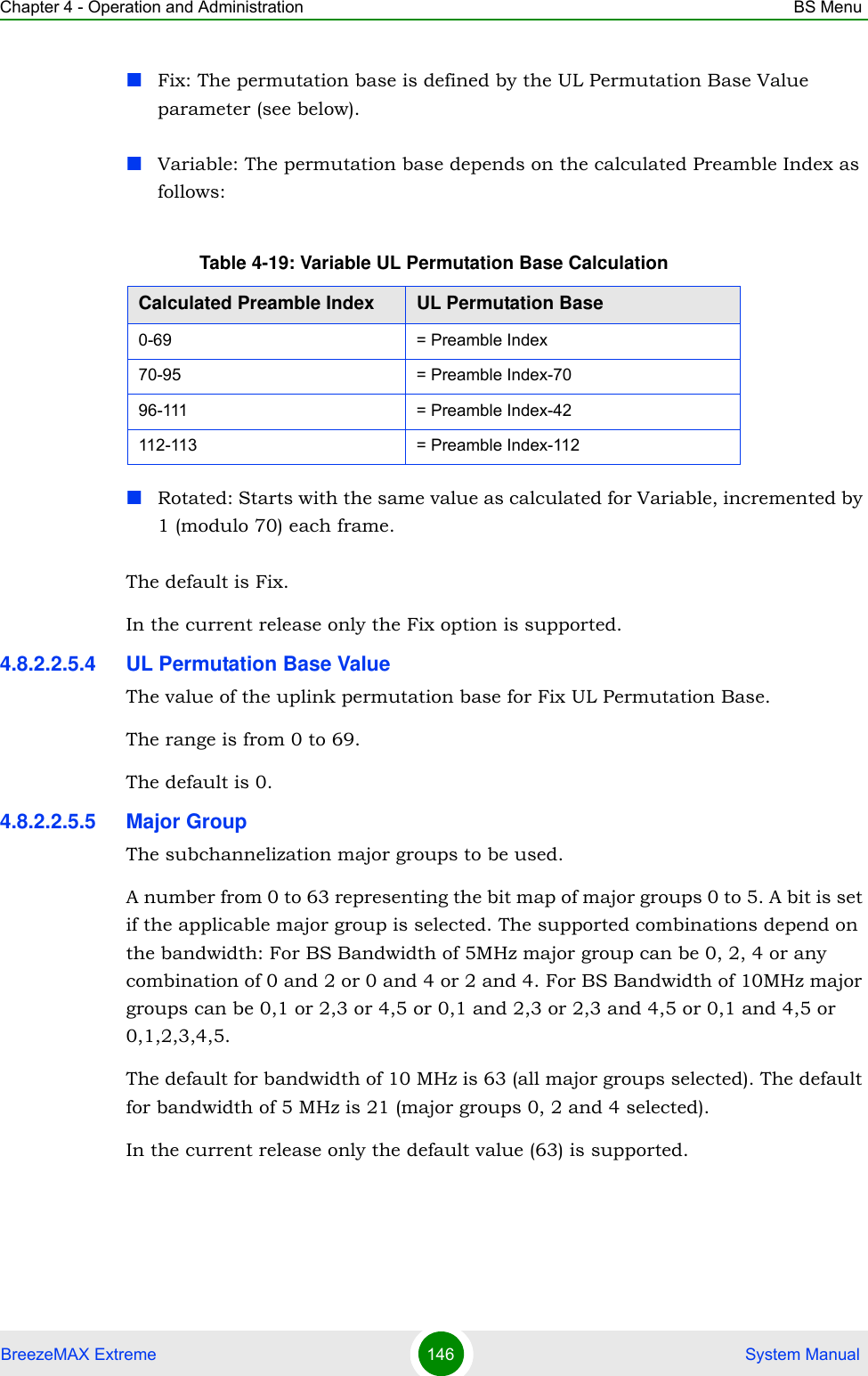
Alvarion Technologies EXTR-36 Base station transceiver User Manual BreezeMAX Extreme System Manual
Alvarion Technologies Ltd. Base station transceiver BreezeMAX Extreme System Manual
Contents
- 1. User manual
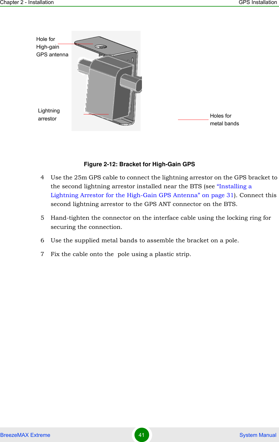
- 2. Rev2 of the Users manual
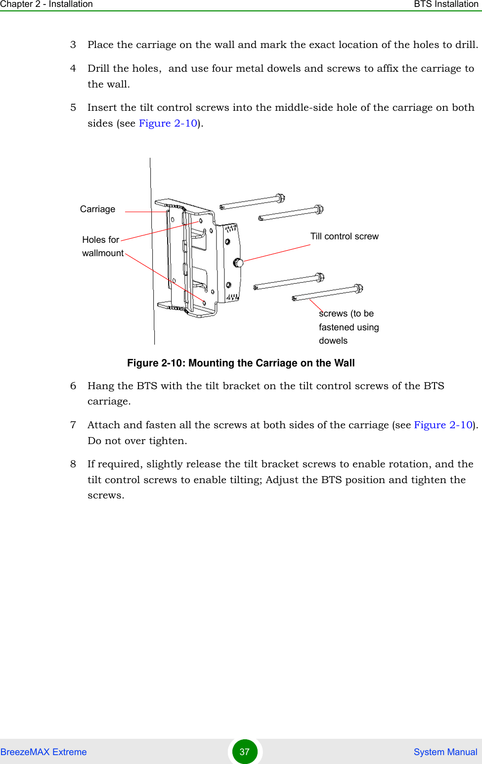
- 3. user manual
User manual