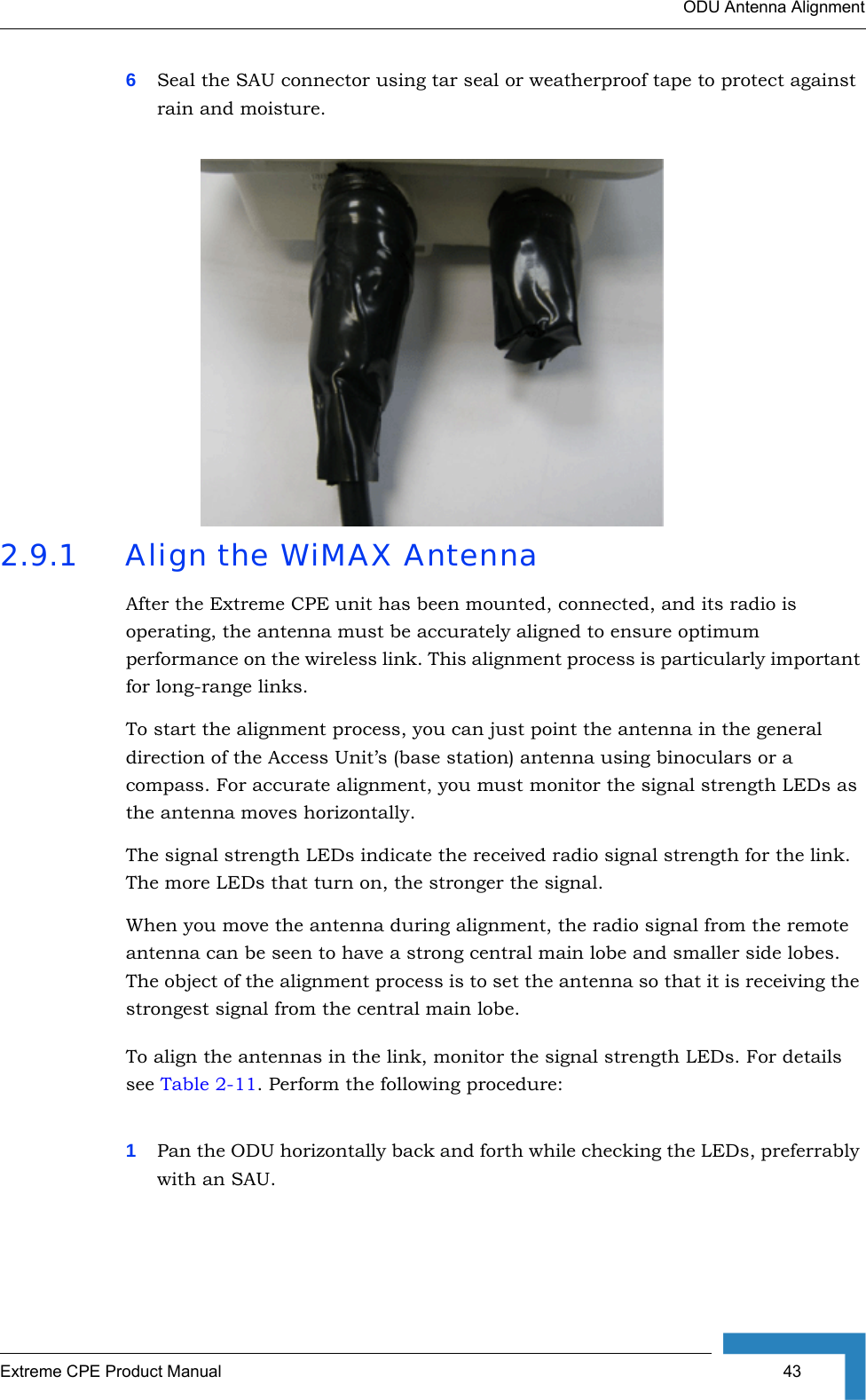
Alvarion Technologies EXTR-CPE-50 BreezeMAX Extreme CPE System User Manual OD210 UG R01
Alvarion Technologies Ltd. BreezeMAX Extreme CPE System OD210 UG R01
UserManual.wiki
>
Alvarion Technologies
>
EXTR CPE 50 User Manual
Manual
Navigation menu
Upload a User Manual
Namespaces
Wiki Guide
HTML
PDF
Info
Views
User Manual
Discussion / Help
Navigation

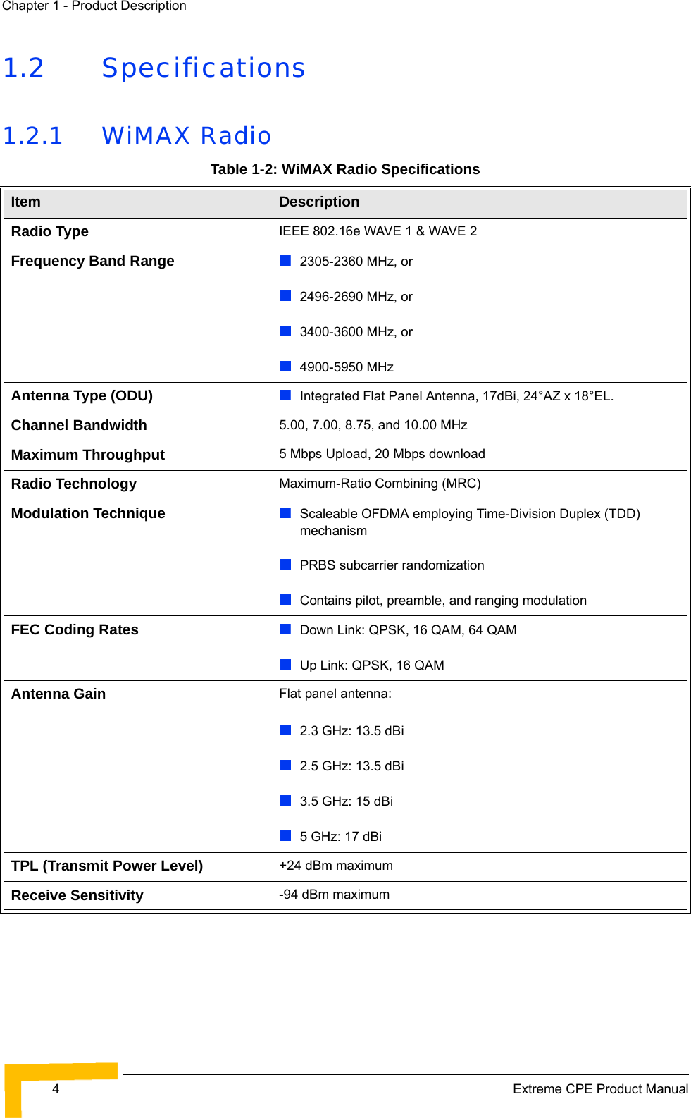
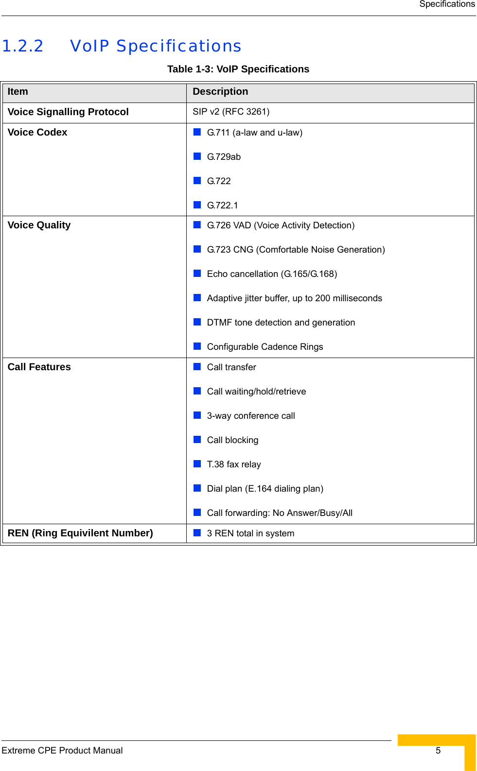
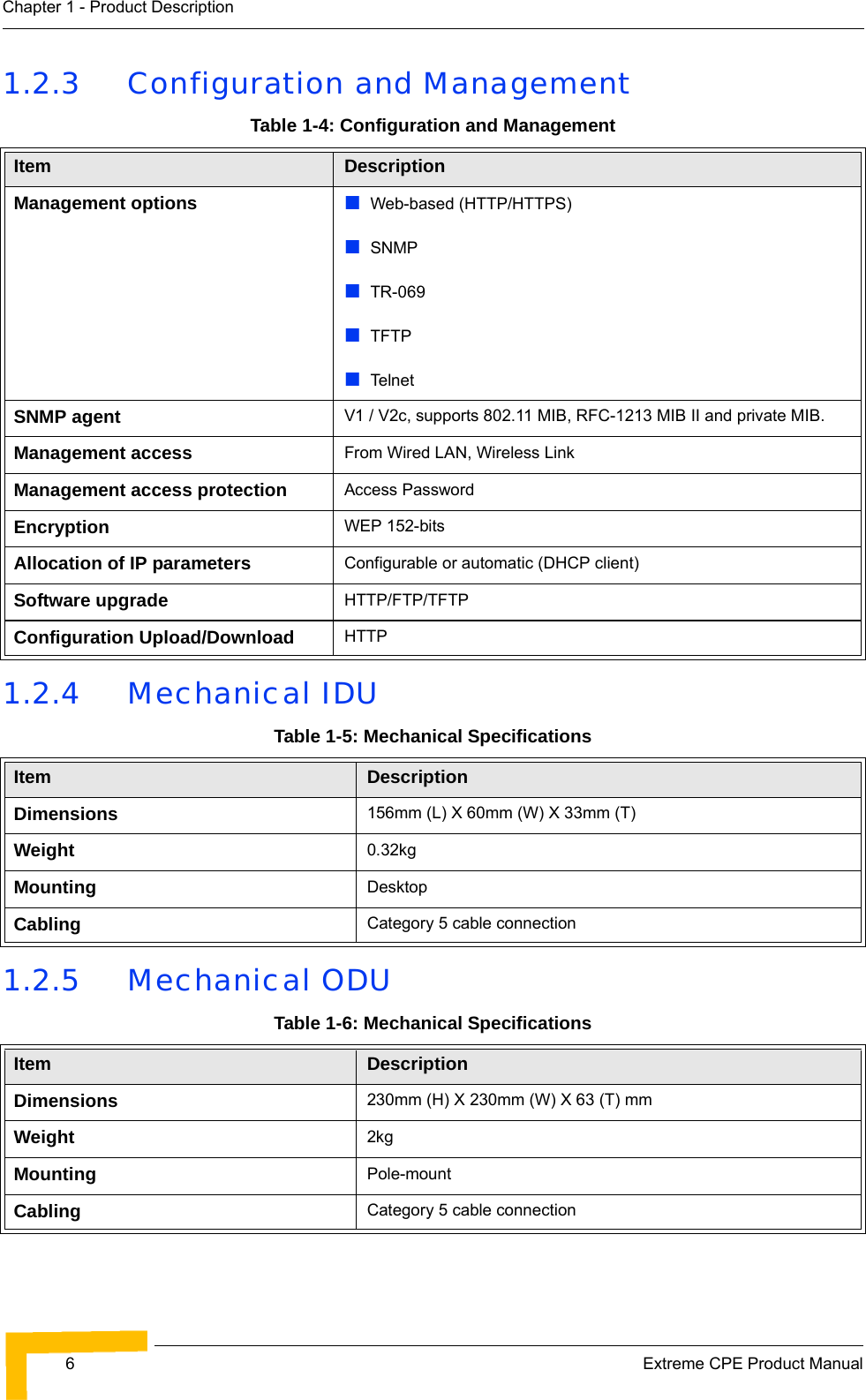
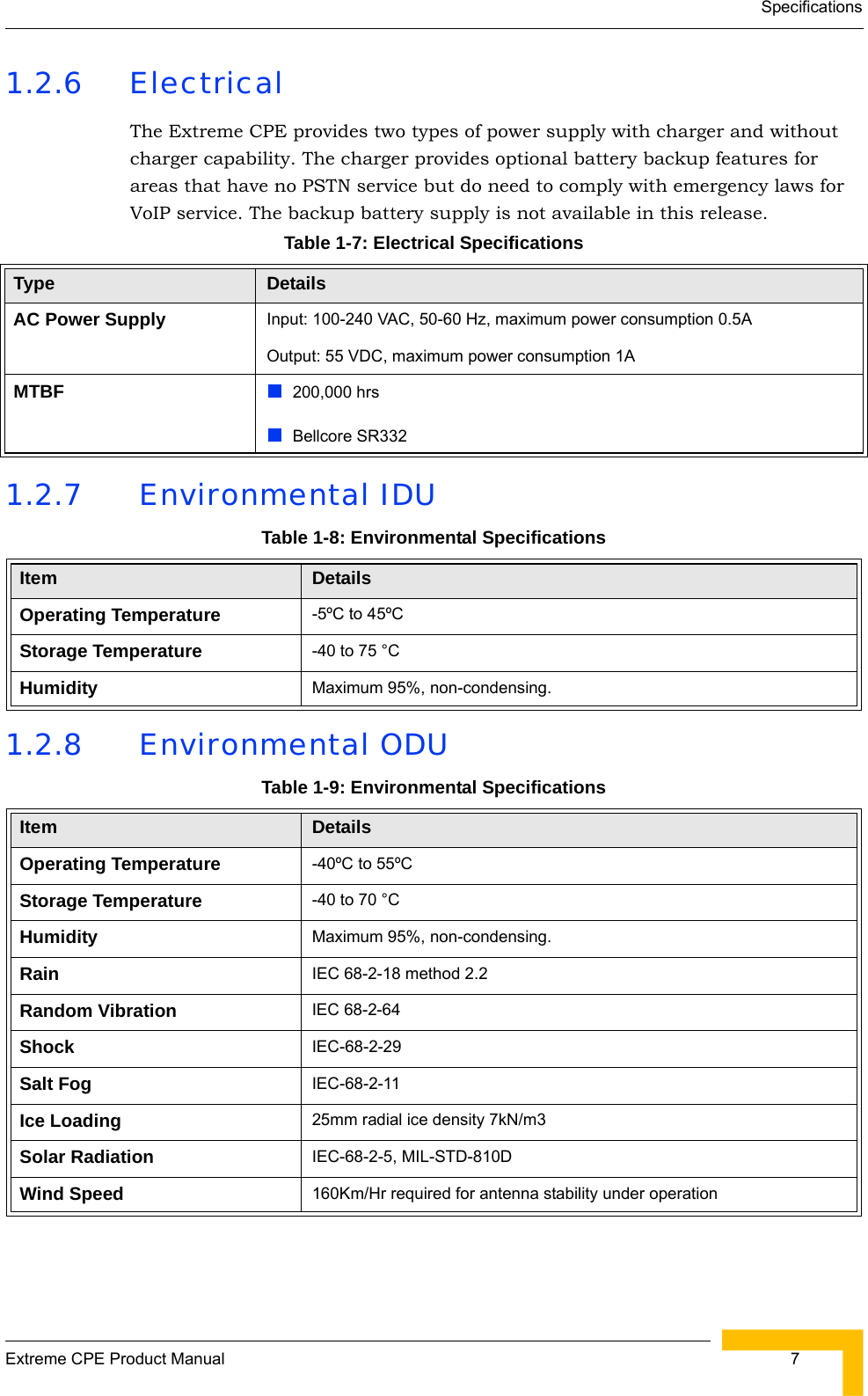


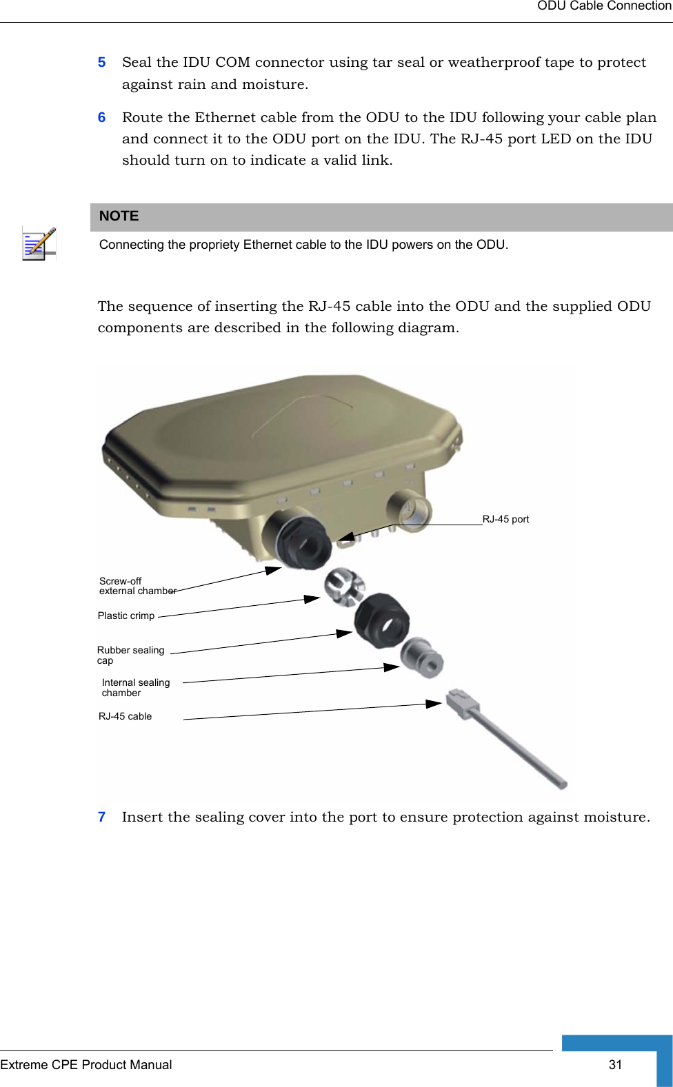
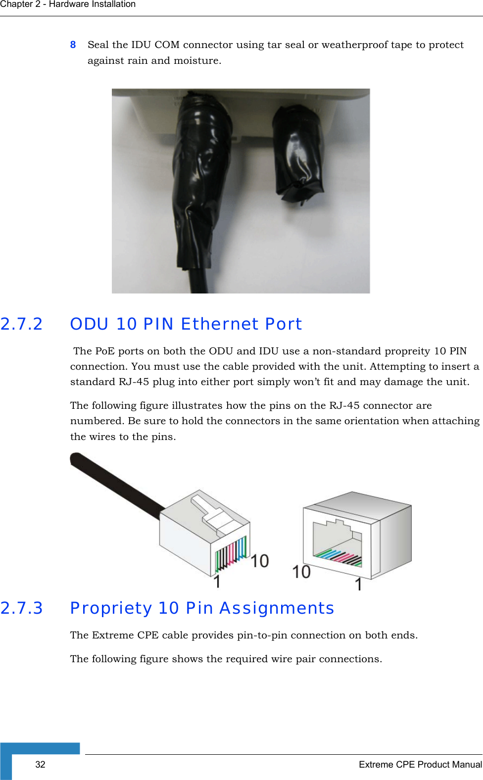
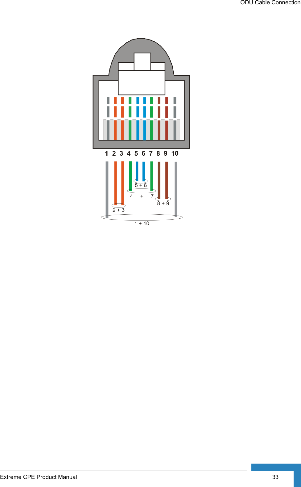
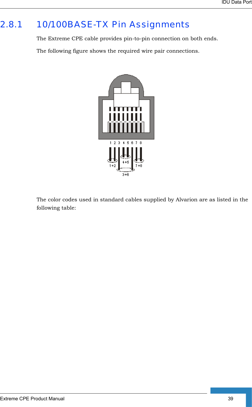
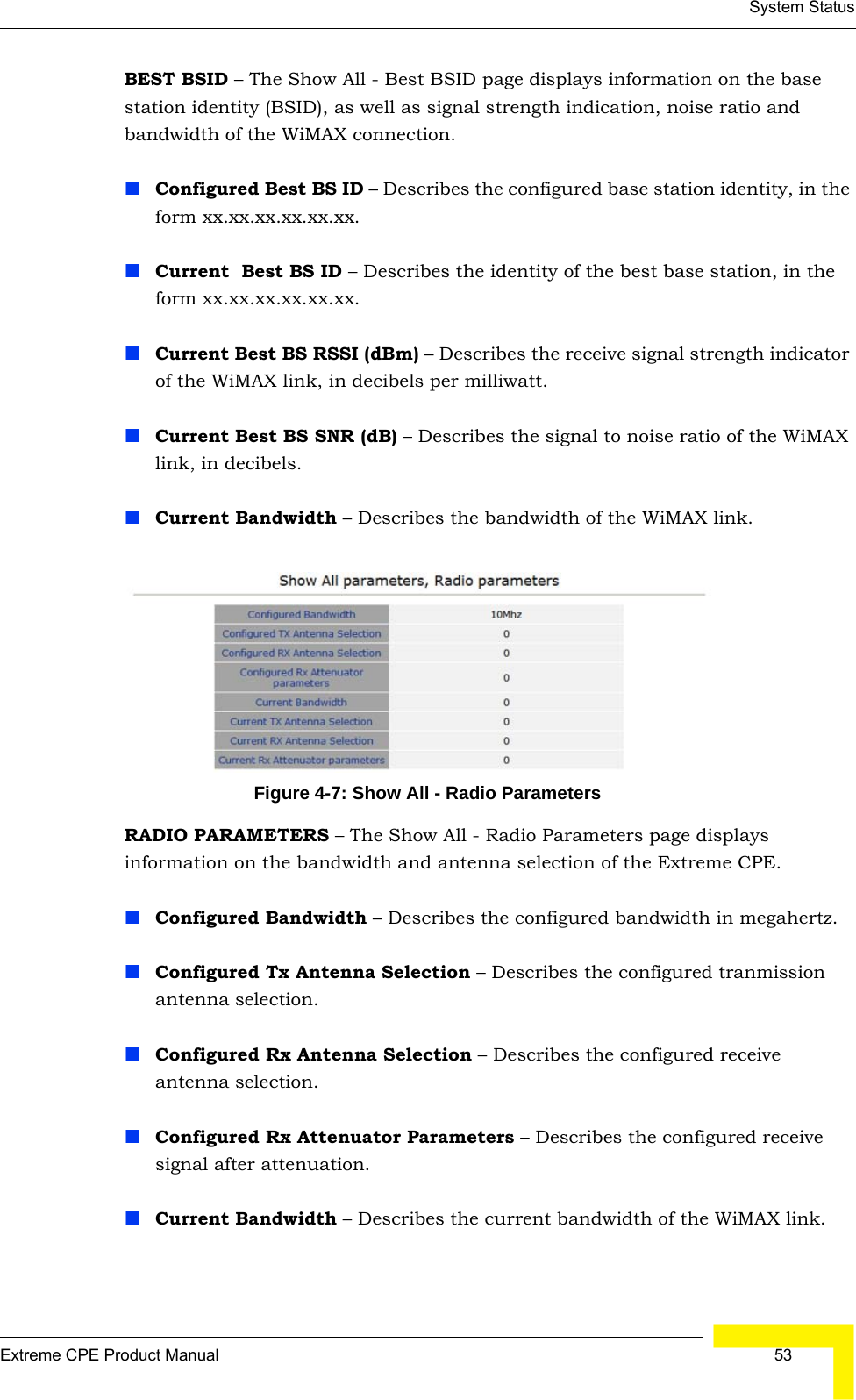
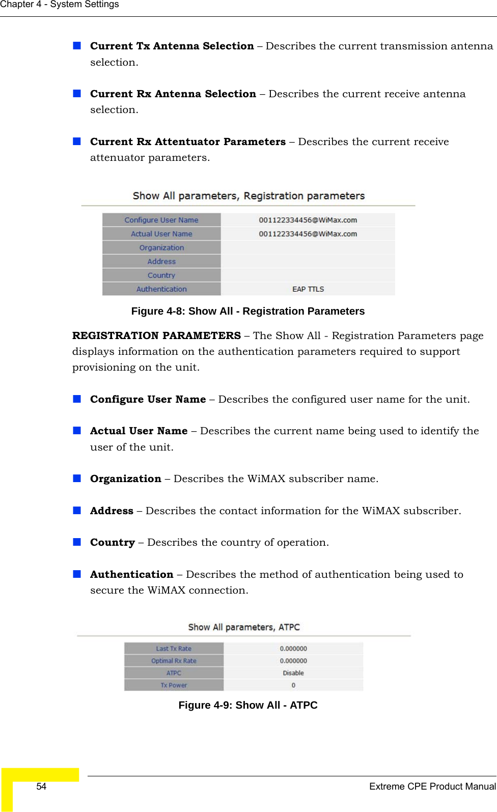
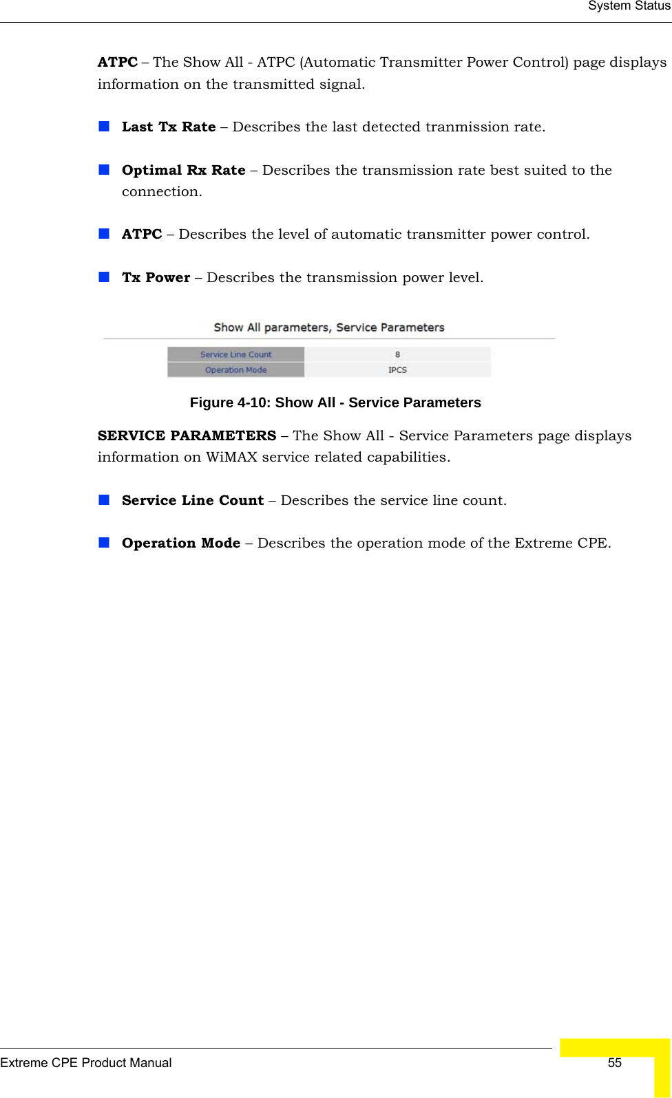
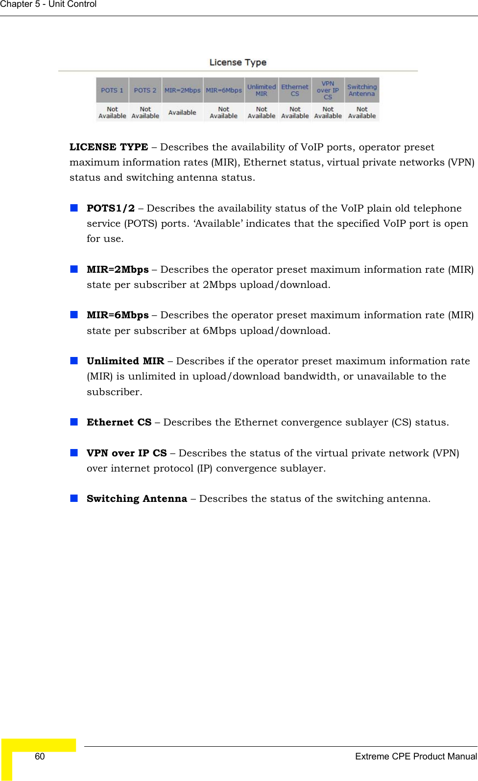
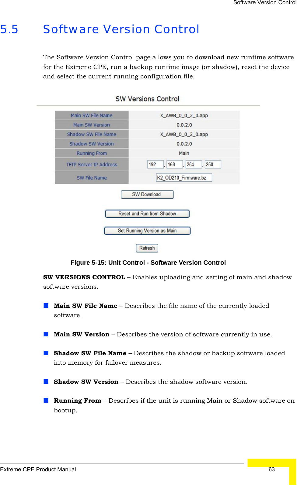
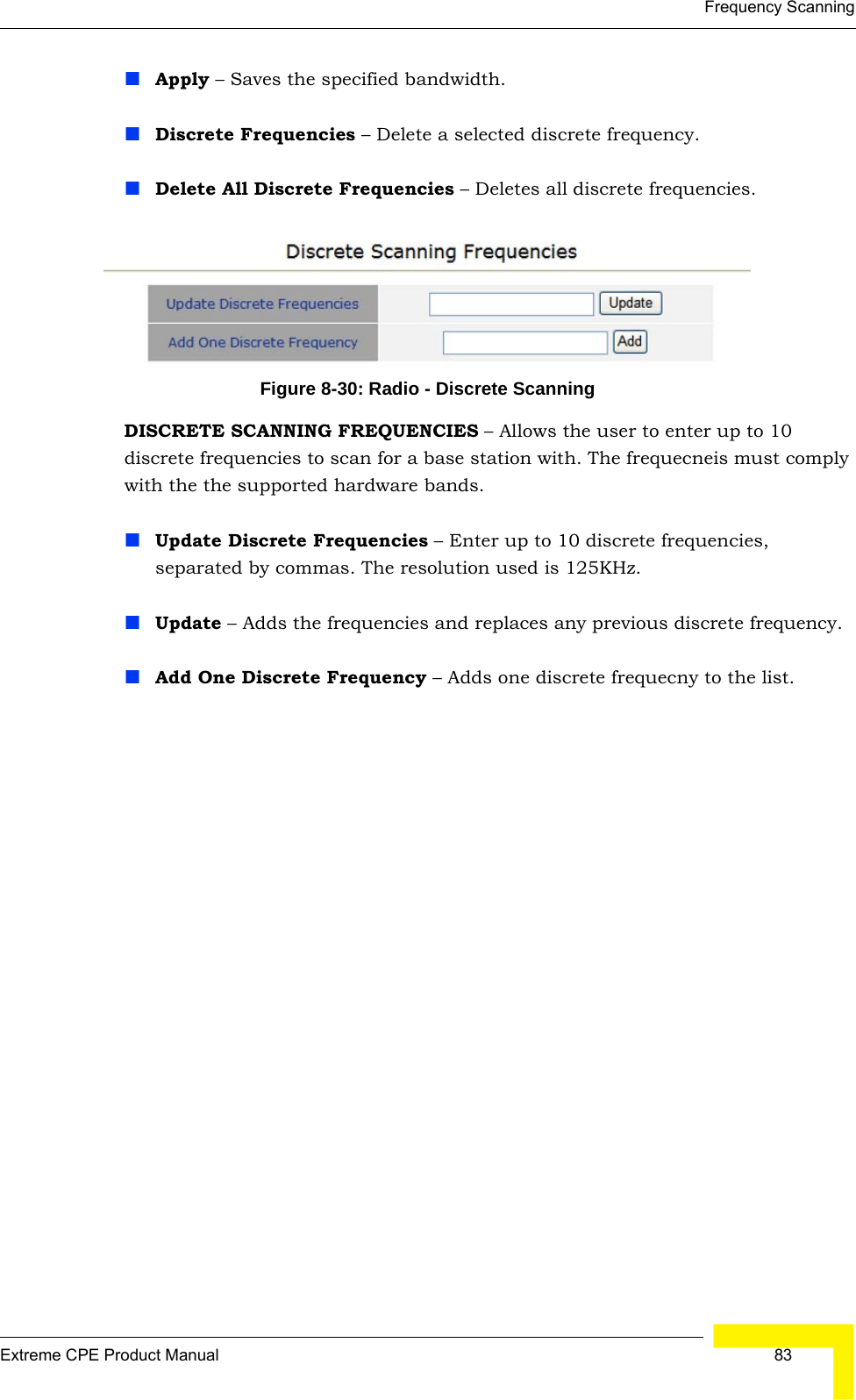
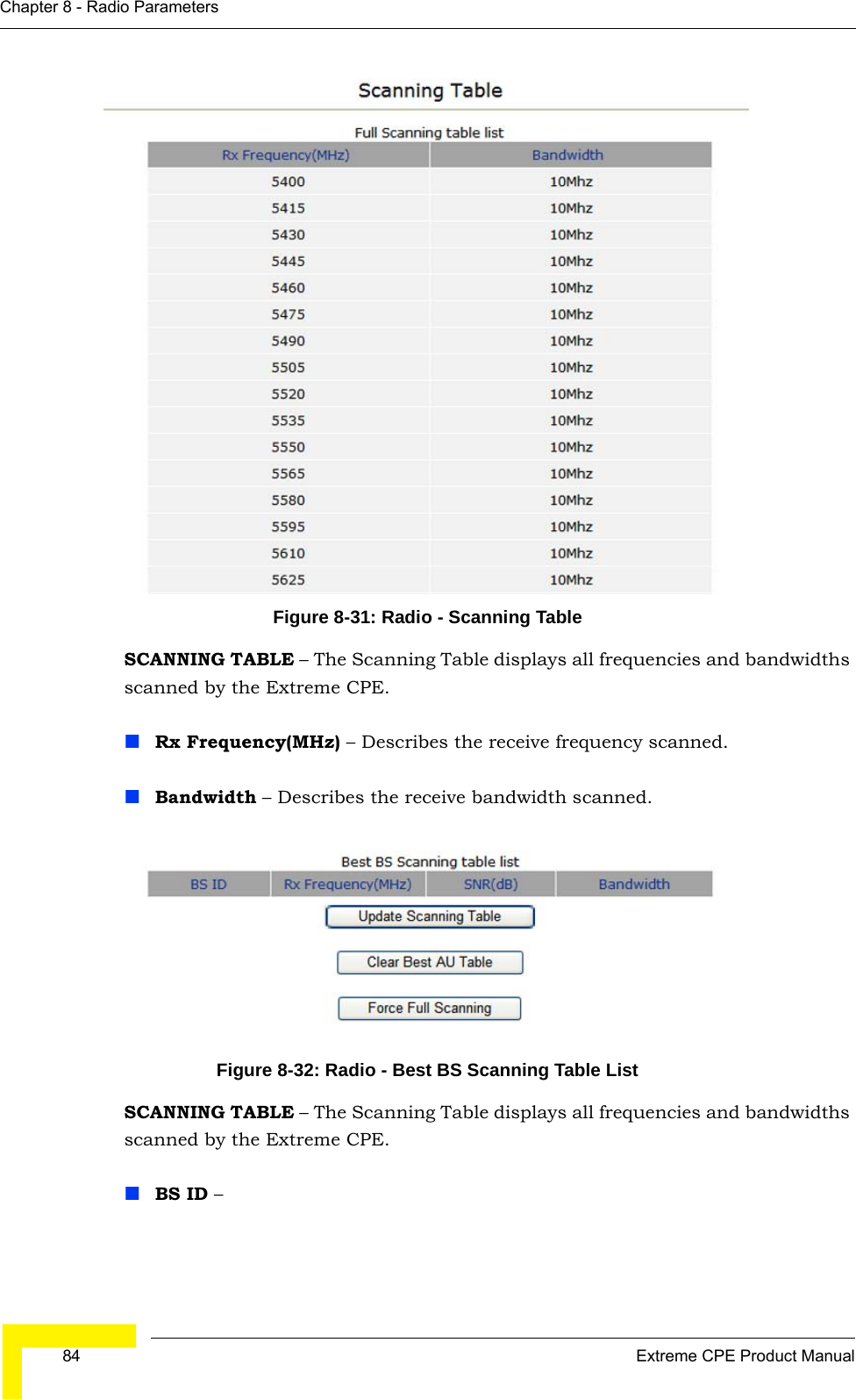
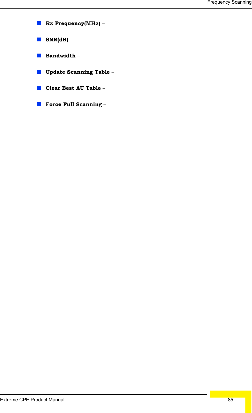
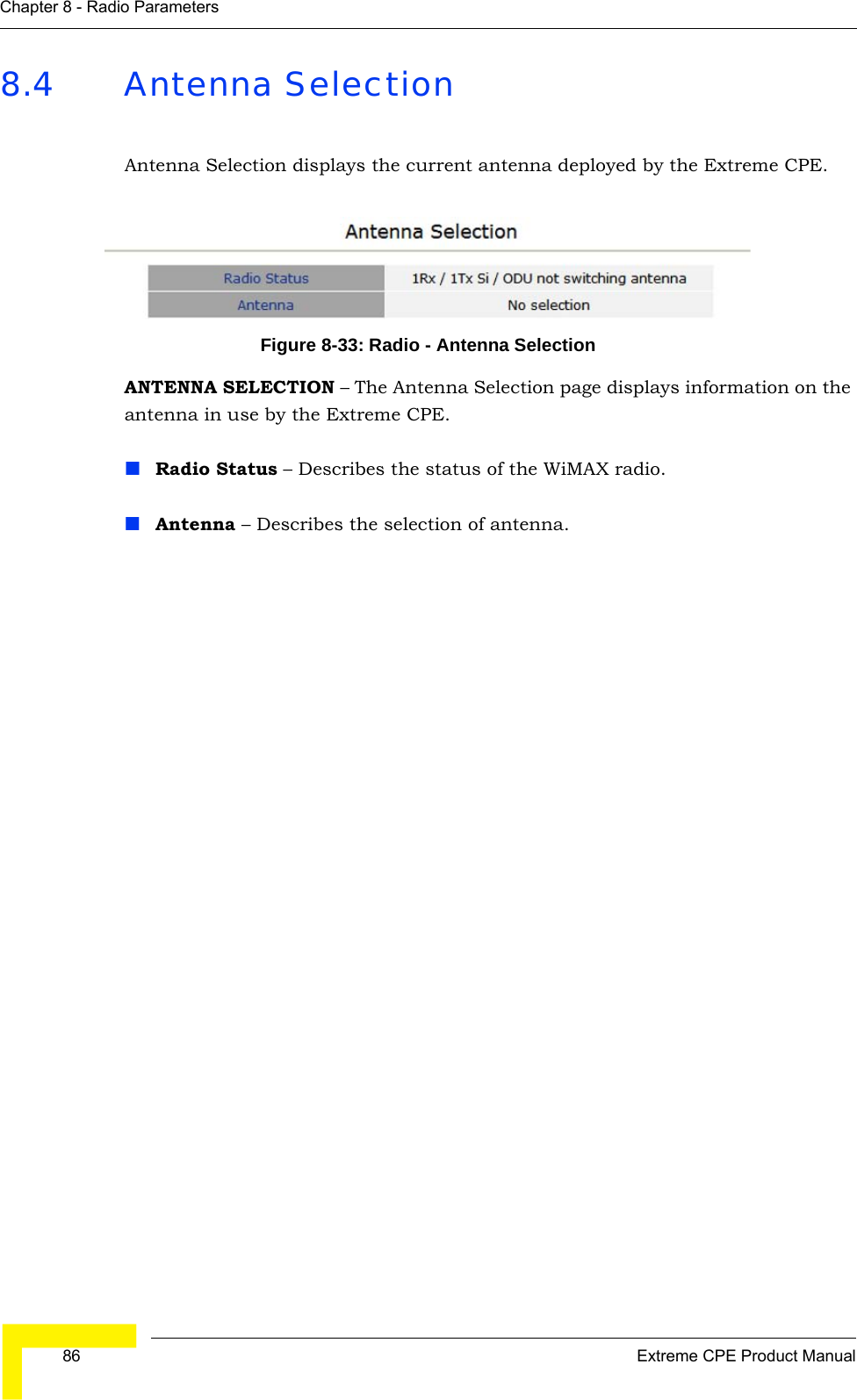
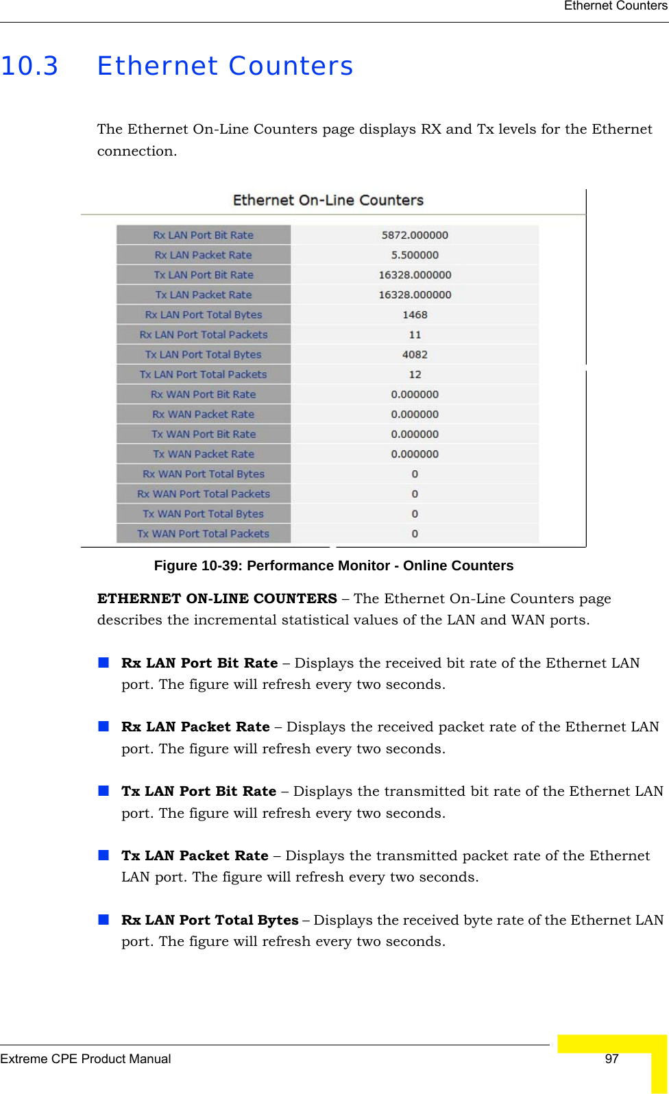
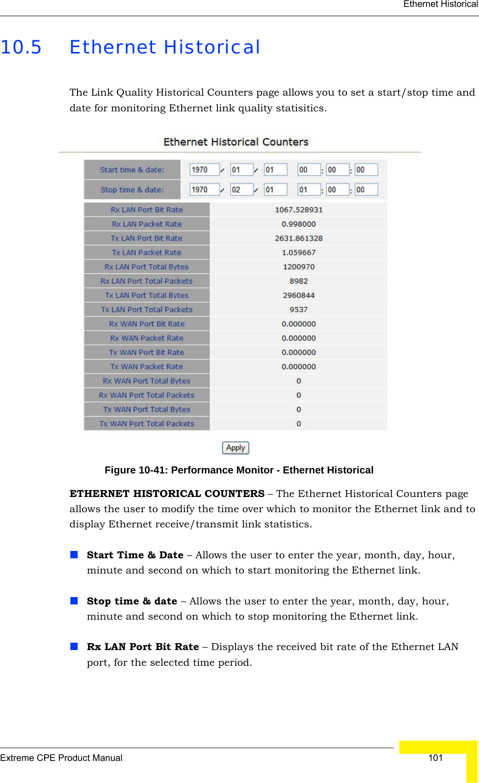
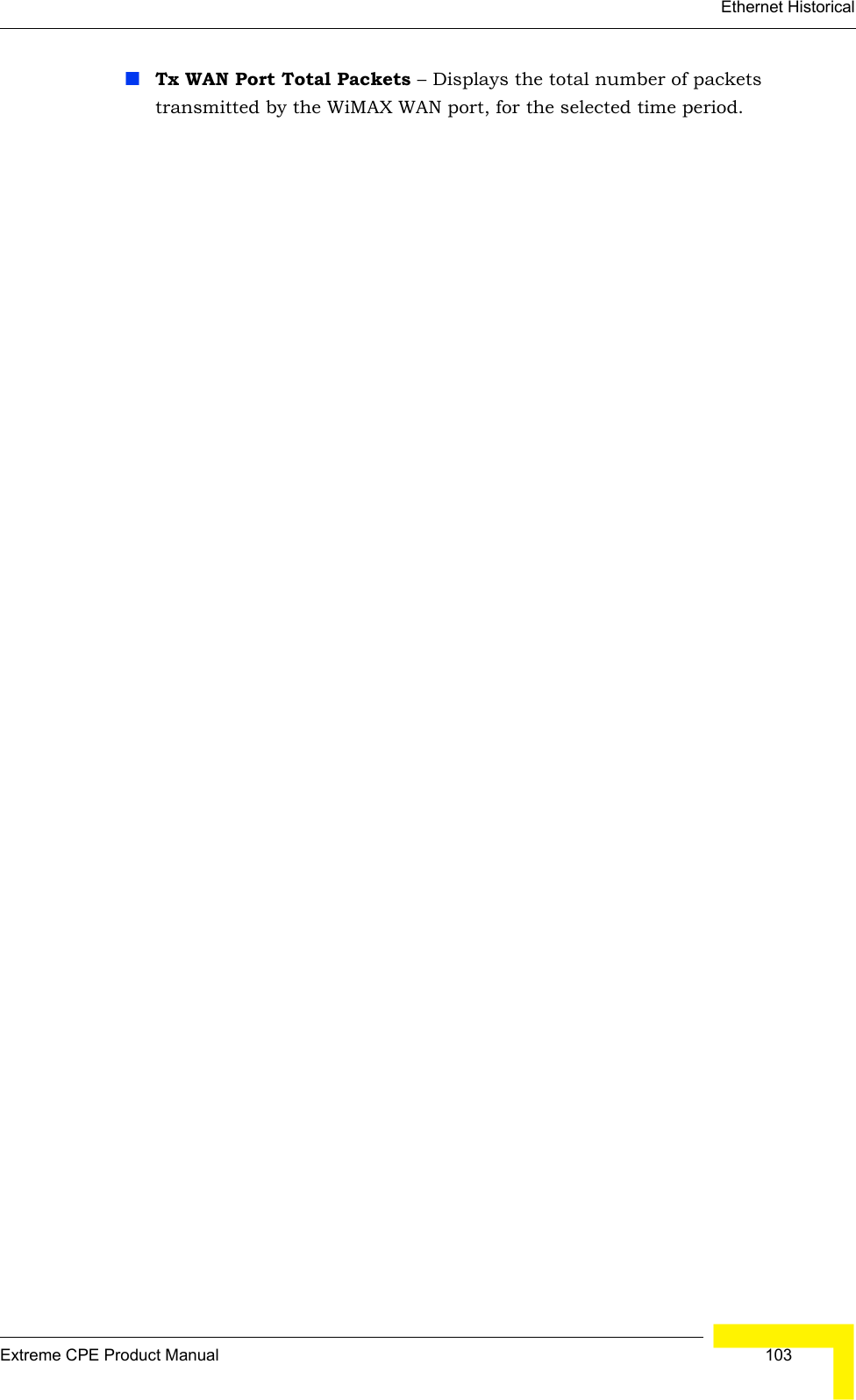
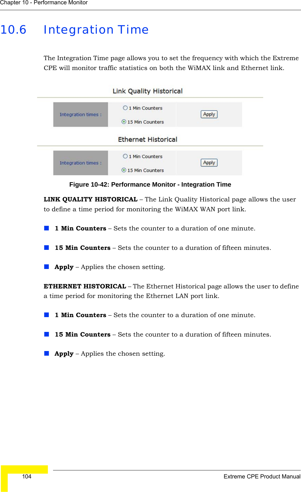
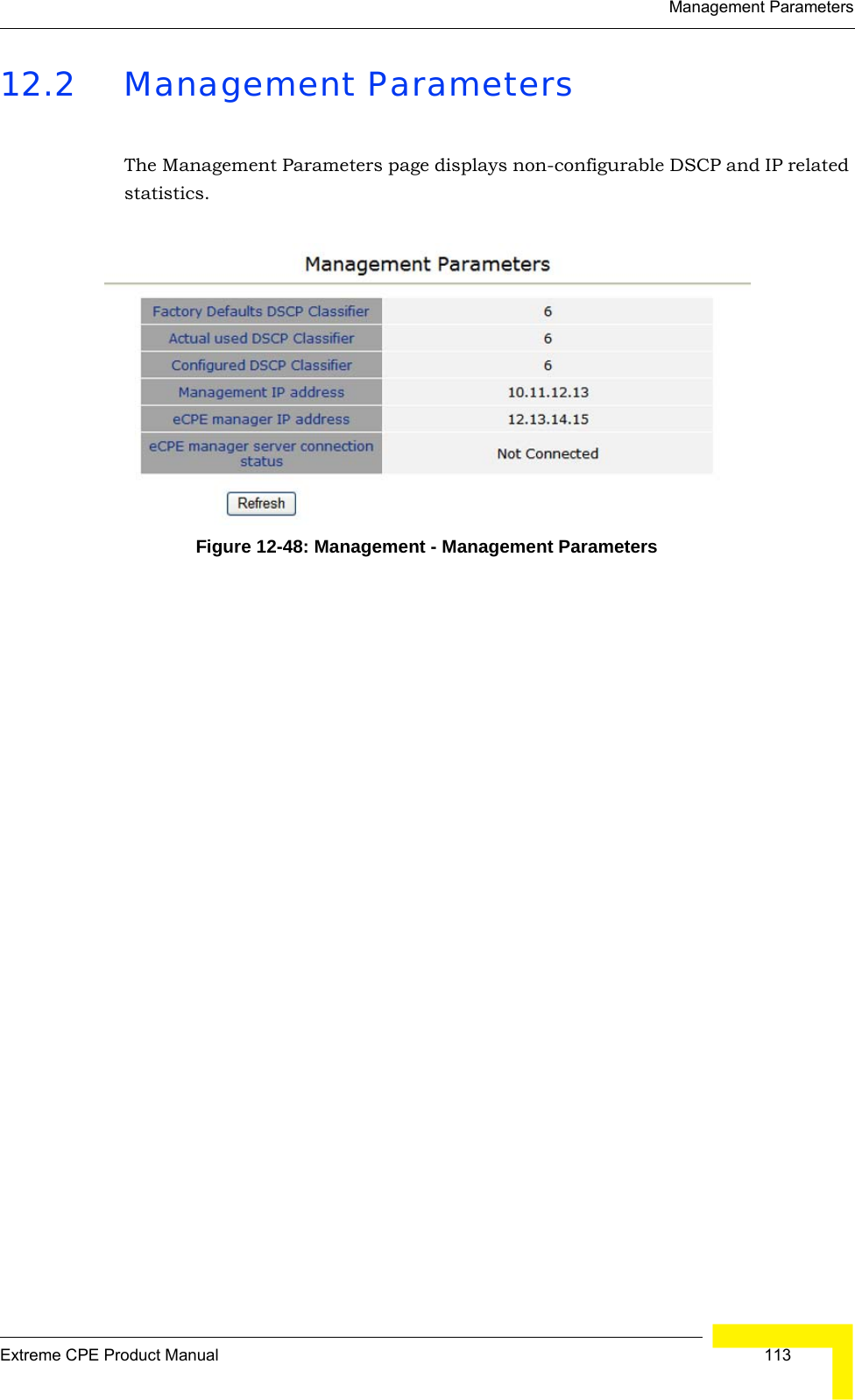
![62 Extreme CPE Product ManualChapter 5 - Unit Control5.4 Change PasswordThe Change Password page enables you to create a new password for access to the Extreme CPE. It is advisable to change the factory default password upon receipt of your Extreme CPE device.Figure 5-14: Unit Control - Change PasswordCHANGE PASSWORD – Allows changing of the current user password for security purposes.Old Password – Prompts you to enter your current password.New Password – Prompts you to enter a new password. (Length: 1-20 characters, cannot include the characters ‘<>?:;,.’”{[}]/\|,’ and is case sentivitive.Confirm New Password – Prompts you to re-enter the new password.Save New Password – Clicking ‘Save New Password’ saves the new password and deletes the old password.Refresh – Clicking ‘Refresh’ clears all information boxes.](https://usermanual.wiki/Alvarion-Technologies/EXTR-CPE-50/User-Guide-1527417-Page-86.png)