Alvarion Technologies EXTR-CPE-58 BreezeMAX Extreme CPE System (5.8 GHz) User Manual BreezeMAX PRO 5000 CPE Product Manual
Alvarion Technologies Ltd. BreezeMAX Extreme CPE System (5.8 GHz) BreezeMAX PRO 5000 CPE Product Manual
Users Manual

BreezeMAX® PRO 5000 CPE
Product Manual
Software Version 4.6
June 2009
P/N 215315

Document History
BreezeMAX PRO 5000 CPE ii Product Manual
Document History
Topic Description Date Issued
First Release New Product Manual SW Version 4.6,
June 2009

Legal Rights
BreezeMAX PRO 5000 CPE iii Product Manual
Legal Rights
© Copyright 2009 Alvarion Ltd. All rights reserved.
The material contained herein is proprietary, privileged, and confidential and
owned by Alvarion or its third party licensors. No disclosure thereof shall be made
to third parties without the express written permission of Alvarion Ltd.
Alvarion Ltd. reserves the right to alter the equipment specifications and
descriptions in this publication without prior notice. No part of this publication
shall be deemed to be part of any contract or warranty unless specifically
incorporated by reference into such contract or warranty.
Trade Names
Alvarion®, BreezeCOM®, WALKair®, WALKnet®, BreezeNET®, BreezeACCESS®,
BreezeLINK®, BreezeMAX®, BreezeLITE®, BreezePHONE®, 4Motion®,
BreezeCONFIG™, AlvariSTAR™, AlvariCRAFT™, MGW™, eMGW™ and/or other
products and/or services referenced here in are either registered trademarks,
trademarks or service marks of Alvarion Ltd.
All other names are or may be the trademarks of their respective owners.
“WiMAX Forum” is a registered trademark of the WiMAX Forum. “WiMAX,” the
WiMAX Forum logo, “WiMAX Forum Certified,” and the WiMAX Forum Certified
logo are trademarks of the WiMAX Forum.
Statement of Conditions
The information contained in this manual is subject to change without notice.
Alvarion Ltd. shall not be liable for errors contained herein or for incidental or
consequential damages in connection with the furnishing, performance, or use of
this manual or equipment supplied with it.
Warranties and Disclaimers
All Alvarion Ltd. ("Alvarion") products purchased from Alvarion or through any of
Alvarion's authorized resellers are subject to the following warranty and product
liability terms and conditions.
Exclusive Warranty
(a) Alvarion warrants that the Product hardware it supplies and the tangible
media on which any software is installed, under normal use and conditions, will
be free from significant defects in materials and workmanship for a period of
fourteen (14) months from the date of shipment of a given Product to Purchaser
(the "Warranty Period"). Alvarion will, at its sole option and as Purchaser's sole

Legal Rights
BreezeMAX PRO 5000 CPE iv Product Manual
remedy, repair or replace any defective Product in accordance with Alvarion'
standard R&R procedure.
(b) With respect to the Firmware, Alvarion warrants the correct functionality
according to the attached documentation, for a period of fourteen (14) month from
invoice date (the "Warranty Period")". During the Warranty Period, Alvarion may
release to its Customers firmware updates, which include additional performance
improvements and/or bug fixes, upon availability (the "Warranty"). Bug fixes,
temporary patches and/or workarounds may be supplied as Firmware updates.
Additional hardware, if required, to install or use Firmware updates must be
purchased by the Customer. Alvarion will be obligated to support solely the two (2)
most recent Software major releases.
ALVARION SHALL NOT BE LIABLE UNDER THIS WARRANTY IF ITS TESTING
AND EXAMINATION DISCLOSE THAT THE ALLEGED DEFECT IN THE PRODUCT
DOES NOT EXIST OR WAS CAUSED BY PURCHASER'S OR ANY THIRD
PERSON'S MISUSE, NEGLIGENCE, IMPROPER INSTALLATION OR IMPROPER
TESTING, UNAUTHORIZED ATTEMPTS TO REPAIR, OR ANY OTHER CAUSE
BEYOND THE RANGE OF THE INTENDED USE, OR BY ACCIDENT, FIRE,
LIGHTNING OR OTHER HAZARD.
Disclaimer
(a) The Software is sold on an "AS IS" basis. Alvarion, its affiliates or its licensors
MAKE NO WARRANTIES, WHATSOEVER, WHETHER EXPRESS OR IMPLIED,
WITH RESPECT TO THE SOFTWARE AND THE ACCOMPANYING
DOCUMENTATION. ALVARION SPECIFICALLY DISCLAIMS ALL IMPLIED
WARRANTIES OF MERCHANTABILITY AND FITNESS FOR A PARTICULAR
PURPOSE AND NON-INFRINGEMENT WITH RESPECT TO THE SOFTWARE.
UNITS OF PRODUCT (INCLUDING ALL THE SOFTWARE) DELIVERED TO
PURCHASER HEREUNDER ARE NOT FAULT-TOLERANT AND ARE NOT
DESIGNED, MANUFACTURED OR INTENDED FOR USE OR RESALE IN
APPLICATIONS WHERE THE FAILURE, MALFUNCTION OR INACCURACY OF
PRODUCTS CARRIES A RISK OF DEATH OR BODILY INJURY OR SEVERE
PHYSICAL OR ENVIRONMENTAL DAMAGE ("HIGH RISK ACTIVITIES"). HIGH
RISK ACTIVITIES MAY INCLUDE, BUT ARE NOT LIMITED TO, USE AS PART OF
ON-LINE CONTROL SYSTEMS IN HAZARDOUS ENVIRONMENTS REQUIRING
FAIL-SAFE PERFORMANCE, SUCH AS IN THE OPERATION OF NUCLEAR
FACILITIES, AIRCRAFT NAVIGATION OR COMMUNICATION SYSTEMS, AIR
TRAFFIC CONTROL, LIFE SUPPORT MACHINES, WEAPONS SYSTEMS OR
OTHER APPLICATIONS REPRESENTING A SIMILAR DEGREE OF POTENTIAL
HAZARD. ALVARION SPECIFICALLY DISCLAIMS ANY EXPRESS OR IMPLIED
WARRANTY OF FITNESS FOR HIGH RISK ACTIVITIES.

Legal Rights
BreezeMAX PRO 5000 CPE v Product Manual
(b) PURCHASER'S SOLE REMEDY FOR BREACH OF THE EXPRESS
WARRANTIES ABOVE SHALL BE REPLACEMENT OR REFUND OF THE
PURCHASE PRICE AS SPECIFIED ABOVE, AT ALVARION'S OPTION. TO THE
FULLEST EXTENT ALLOWED BY LAW, THE WARRANTIES AND REMEDIES SET
FORTH IN THIS AGREEMENT ARE EXCLUSIVE AND IN LIEU OF ALL OTHER
WARRANTIES OR CONDITIONS, EXPRESS OR IMPLIED, EITHER IN FACT OR BY
OPERATION OF LAW, STATUTORY OR OTHERWISE, INCLUDING BUT NOT
LIMITED TO WARRANTIES, TERMS OR CONDITIONS OF MERCHANTABILITY,
FITNESS FOR A PARTICULAR PURPOSE, SATISFACTORY QUALITY,
CORRESPONDENCE WITH DESCRIPTION, NON-INFRINGEMENT, AND
ACCURACY OF INFORMATION GENERATED. ALL OF WHICH ARE EXPRESSLY
DISCLAIMED. ALVARION' WARRANTIES HEREIN RUN ONLY TO PURCHASER,
AND ARE NOT EXTENDED TO ANY THIRD PARTIES. ALVARION NEITHER
ASSUMES NOR AUTHORIZES ANY OTHER PERSON TO ASSUME FOR IT ANY
OTHER LIABILITY IN CONNECTION WITH THE SALE, INSTALLATION,
MAINTENANCE OR USE OF ITS PRODUCTS.
Limitation of Liability
(a) ALVARION SHALL NOT BE LIABLE TO THE PURCHASER OR TO ANY THIRD
PARTY, FOR ANY LOSS OF PROFITS, LOSS OF USE, INTERRUPTION OF
BUSINESS OR FOR ANY INDIRECT, SPECIAL, INCIDENTAL, PUNITIVE OR
CONSEQUENTIAL DAMAGES OF ANY KIND, WHETHER ARISING UNDER
BREACH OF CONTRACT, TORT (INCLUDING NEGLIGENCE), STRICT LIABILITY
OR OTHERWISE AND WHETHER BASED ON THIS AGREEMENT OR
OTHERWISE, EVEN IF ADVISED OF THE POSSIBILITY OF SUCH DAMAGES.
(b) TO THE EXTENT PERMITTED BY APPLICABLE LAW, IN NO EVENT SHALL
THE LIABILITY FOR DAMAGES HEREUNDER OF ALVARION OR ITS EMPLOYEES
OR AGENTS EXCEED THE PURCHASE PRICE PAID FOR THE PRODUCT BY
PURCHASER, NOR SHALL THE AGGREGATE LIABILITY FOR DAMAGES TO ALL
PARTIES REGARDING ANY PRODUCT EXCEED THE PURCHASE PRICE PAID
FOR THAT PRODUCT BY THAT PARTY (EXCEPT IN THE CASE OF A BREACH OF
A PARTY'S CONFIDENTIALITY OBLIGATIONS).
Radio Frequency Interference Statement
The Subscriber Unit equipment has been tested and found to comply with the
limits for a class B digital device, pursuant to ETSI EN 301 489-1 rules and Part
15 of the FCC Rules. These limits are designed to provide reasonable protection
against harmful interference when the equipment is operated in a residential
environment notwithstanding use in commercial, business and industrial
environments. This equipment generates, uses, and can radiate radio frequency
energy and, if not installed and used in accordance with the instruction manual,
may cause harmful interference to radio communications.

Legal Rights
BreezeMAX PRO 5000 CPE vi Product Manual
FCC Radiation Hazard Warning
Outdoor CPE - To comply with FCC RF exposure requirements in Section 1.1307
and 2.1091 of FCC Rules, the antenna be used for this transmitter must be
fixed-mounted on outdoor permanent structures with a separation distance of at
least 120 cm from all persons and must not be co-located or operating in
conjunction with any other antenna or transmitter.
R&TTE Compliance Statement
This equipment complies with the appropriate essential requirements of Article 3
of the R&TTE Directive 1999/5/EC.
Safety Considerations - General
For the following safety considerations, "Instrument" means the BreezeMAX units'
components and their cables.
Caution
To avoid electrical shock, do not perform any servicing unless you are qualified to
do so.
Line Voltage
Before connecting this instrument to the power line, make sure that the voltage of
the power source matches the requirements of the instrument.
Radio
The instrument transmits radio energy during normal operation. To avoid possible
harmful exposure to this energy, do not stand or work for extended periods of time
in front of its antenna. The long-term characteristics or the possible physiological
effects of radio frequency electromagnetic fields have not been yet fully
investigated.
Outdoor Units and Antennas Installation and Grounding
Ensure that outdoor units, antennas and supporting structures are properly
installed to eliminate any physical hazard to either people or property. Make sure
that the installation of the outdoor unit, antenna and cables is performed in
accordance with all relevant national and local building and safety codes. Even
where grounding is not mandatory according to applicable regulation and national
codes, it is highly recommended to ensure that the outdoor unit and the antenna
mast (when using external antenna) are grounded and suitable lightning
protection devices are used so as to provide protection against voltage surges and
static charges. In any event, Alvarion is not liable for any injury, damage or
regulation violations associated with or caused by installation, grounding or
lightning protection.

Legal Rights
BreezeMAX PRO 5000 CPE vii Product Manual
Disposal of Electronic and Electrical Waste
Disposal of Electronic and Electrical Waste
Pursuant to the WEEE EU Directive electronic and electrical waste must not be disposed of with
unsorted waste. Please contact your local recycling authority for disposal of this product.

Important Notice
BreezeMAX PRO 5000 CPE viii Product Manual
Important Notice
This user manual is delivered subject to the following conditions and restrictions:
This manual contains proprietary information belonging to Alvarion Ltd. Such
information is supplied solely for the purpose of assisting properly authorized
users of the respective Alvarion products.
No part of its contents may be used for any other purpose, disclosed to any
person or firm or reproduced by any means, electronic and mechanical,
without the express prior written permission of Alvarion Ltd.
The text and graphics are for the purpose of illustration and reference only.
The specifications on which they are based are subject to change without
notice.
The software described in this document is furnished under a license. The
software may be used or copied only in accordance with the terms of that
license.
Information in this document is subject to change without notice. Corporate
and individual names and data used in examples herein are fictitious unless
otherwise noted.
Alvarion Ltd. reserves the right to alter the equipment specifications and
descriptions in this publication without prior notice. No part of this
publication shall be deemed to be part of any contract or warranty unless
specifically incorporated by reference into such contract or warranty.
The information contained herein is merely descriptive in nature, and does not
constitute an offer for the sale of the product described herein.
Any changes or modifications of equipment, including opening of the
equipment not expressly approved by Alvarion Ltd. will void equipment
warranty and any repair thereafter shall be charged for. It could also void the
user's authority to operate the equipment.

About This Manual
BreezeMAX PRO 5000 CPE ix Product Manual
About This Manual
This document describes and explains how to install and manage the BreezeMAX
PRO 5000 CPE units using SW Version 4.6.
This document contains the following chapters:
Chapter 1 - Product description: Describes the PRO 5000 CPE, and its
specifications.
Chapter 2 - Installation: Describes how to install the PRO 5000 CPE.
Chapter 3 - Commissioning: Describes how to configure basic parameters,
align the antenna and validate unit operation.
Chapter 4 - Operation and Administration: Describes how to use the web
interface application for configuring parameters, checking system status and
monitoring performance.
Appendix A - Provides troubleshooting guidelines for CPE.
Glossary - A listing of commonly used terms.

Contents
BreezeMAX PRO 5000 CPE x Product Manual
Contents
Chapter 1 - Products Description............................................................1
1.1 BreezeMAX CPEs .......................................................................................................3
1.2 Introducing BreezeMAX PRO 5000 CPE...................................................................4
1.3 Specifications.............................................................................................................5
1.3.1 Radio...................................................................................................................5
1.3.2 Sensitivity............................................................................................................6
1.3.3 IDU/ODU Communication...................................................................................6
1.3.4 Data Communication (Ethernet Port)..................................................................6
1.3.5 Configuration and Management..........................................................................7
1.3.6 Environmental .....................................................................................................8
1.3.7 Standards Compliance, General .........................................................................8
1.3.8 Physical and Electrical ........................................................................................9
Chapter 2 - Installation..........................................................................11
2.1 Installing the ODU of the PRO CPE ........................................................................13
2.1.1 CPE Installation Requirements .........................................................................13
2.1.2 Guidelines for Positioning the ODU ..................................................................14
2.1.3 IDU-ODU Cables...............................................................................................15
2.1.4 Pole Mounting the ODU ....................................................................................15
2.1.5 Connectors........................................................................................................20
2.1.6 Connecting the Cables......................................................................................20
2.2 Installing the IDU-1D Indoor Unit of the PRO 5000 CPE.......................................24
2.2.1 Installation Requirements..................................................................................24
2.2.2 Location.............................................................................................................24
2.2.3 CPE IDU-1D Connectors and LEDs..................................................................25
2.2.4 RESET Button...................................................................................................26
2.2.5 IDU Installation..................................................................................................26
2.2.6 Grounding the ODU-IDU Cable.........................................................................28

Contents
BreezeMAX PRO 5000 CPE xi Product Manual
Chapter 3 - Commissioning ...................................................................29
3.1 Commissioning Steps..............................................................................................31
3.2 Configuring Basic Parameters................................................................................32
3.2.1 The Basic Parameters.......................................................................................32
3.2.2 Configuration Tools...........................................................................................33
3.2.3 Using the Web Configuration Server.................................................................33
3.3 Aligning the PRO CPE’s Antenna...........................................................................35
3.3.1 SU Alignment Unit (SAU)..................................................................................35
3.3.2 Using SAU for Aligning the PRO CPE's Antenna..............................................37
3.4 Operation Verification..............................................................................................39
Chapter 4 - Operation............................................................................40
4.1 Introduction to SU Management.............................................................................42
4.2 Accessing the Web Configuration Server..............................................................43
4.3 Using the Web Configuration Server......................................................................44
4.4 Show All ....................................................................................................................45
4.5 Unit Control Parameters..........................................................................................46
4.5.1 Show .................................................................................................................46
4.5.2 Reset Unit .........................................................................................................48
4.5.3 Change Password.............................................................................................49
4.5.4 SW Versions Control.........................................................................................50
4.5.5 Configuration Control ........................................................................................52
4.5.6 TM/PM Files Control .........................................................................................54
4.5.7 Ethernet Op Mode.............................................................................................55
4.6 Registration Parameters..........................................................................................57
4.6.1 Show .................................................................................................................57
4.6.2 Registration.......................................................................................................58
4.7 BST/AU Parameters .................................................................................................61
4.8 Radio Parameters.....................................................................................................65
4.8.1 Show .................................................................................................................65
4.8.2 Frequency Scanning .........................................................................................65

Contents
BreezeMAX PRO 5000 CPE xii Product Manual
4.8.3 Antenna Selection.............................................................................................69
4.9 ATPC Parameters.....................................................................................................70
4.9.1 Show .................................................................................................................70
4.9.2 ATPC.................................................................................................................71
4.10 Performance Monitor...............................................................................................73
4.10.1 Link Quality Counters Page ..............................................................................73
4.10.2 Ethernet Counters.............................................................................................74
4.10.3 Integration Time ................................................................................................75
4.11 Service Parameters .................................................................................................77
4.12 Management Parameters ........................................................................................79
4.13 Logout.......................................................................................................................80
4.14 Parameters Summary..............................................................................................81
A.1 PRO CPE Troubleshooting......................................................................................86

Figures
BreezeMAX PRO 5000 CPE xiii Product Manual
Figures
Figure 2-1: ODU Pole Installation Using the Special Clamp, Arrow Facing Upwards............17
Figure 2-2: ODU Pole Installation Using the Special Clamp, Arrow Facing Rightwards ........18
Figure 2-3: ODU Pole Installation Using the Tilt Accessory, Vertical Polarization .................19
Figure 2-4: Bottom Panel of the ODU (without sealing covers)..............................................20
Figure 2-5: Ethernet Connector Pin Assignments..................................................................22
Figure 2-6: Inserting the IDU COM Cable into the Sealing Cap.............................................23
Figure 2-7: CPE-IDU-1D Front Panel.....................................................................................25
Figure 2-8: CPE-IDU-1D 3D View ..........................................................................................25
Figure 3-1: Login Window ......................................................................................................33
Figure 3-2: SAU......................................................................................................................35
Figure 4-1: Web Configuration Server - Main Window...........................................................43
Figure 4-2: Reset Unit Page...................................................................................................48
Figure 4-3: Change Password Page ......................................................................................49
Figure 4-4: SW Versions Control Page ..................................................................................50
Figure 4-5: Configuration Control Page..................................................................................52
Figure 4-6: TM & PM File Upload Control Page.....................................................................55
Figure 4-7: Ethernet Operation Mode Page ...........................................................................55
Figure 4-8: Registration Show Page ......................................................................................57
Figure 4-9: Registration Page ................................................................................................58
Figure 4-10: BST/AU Page.......................................................................................................62
Figure 4-11: Radio - Show Page ..............................................................................................65
Figure 4-12: Frequency Scanning Page...................................................................................67
Figure 4-13: Antenna Selection Page ......................................................................................69
Figure 4-14: ATPC Show Page ................................................................................................70
Figure 4-15: ATPC Page ..........................................................................................................71
Figure 4-16: Link Quality Counters Page .................................................................................73
Figure 4-17: Ethernet Counters Page ......................................................................................74

Figures
BreezeMAX PRO 5000 CPE xiv Product Manual
Figure 4-18: Integration Time Page..........................................................................................75
Figure 4-19: Service Page........................................................................................................77
Figure 4-20: Management Page...............................................................................................79
Figure 4-21: Logout Page.........................................................................................................80

Tables
BreezeMAX PRO 5000 CPE xv Product Manual
Tables
Table 1-1: Radio Specifications.....................................................................................................5
Table 1-2: Sensitivity.....................................................................................................................6
Table 1-3: ODU/ODU Communication..........................................................................................6
Table 1-4: Data Communication (Ethernet Port)...........................................................................6
Table 1-5: Configuration and Management...................................................................................7
Table 1-6: Environmental Specifications.......................................................................................8
Table 1-7: Environmental Specifications.......................................................................................8
Table 1-8: Mechanical Specifications............................................................................................9
Table 1-9: Electrical Specifications ...............................................................................................9
Table 1-10: Connectors.................................................................................................................9
Table 2-1: Approved Category 5E Ethernet Cables....................................................................15
Table 2-2: CPE-ODU-PRO Connectors ......................................................................................20
Table 2-3: Cable Color Codes.....................................................................................................22
Table 2-4: CPE-IDU-1D Connectors ...........................................................................................25
Table 2-5: CPE-IDU-1D LEDs.....................................................................................................26
Table 3-1: SU's Basic Parameters ..............................................................................................32
Table 3-2: SAU LEDs..................................................................................................................36
Table 3-3: SAU LINK QUALITY LEDs Functionality ...................................................................37
Table 4-1: Intermediate Steps.....................................................................................................66
Table 4-2: Country Codes ...........................................................................................................72
Table 4-3: SU Parameters Summary ..........................................................................................81

1
Chapter
Products Description


Chapter 1 - Products Description BreezeMAX CPEs
BreezeMAX PRO 5000 CPE 3 Product Manual
1.1 BreezeMAX CPEs
The WiMAX-compatible BreezeMAX PRO 5000 CPE Subscriber Units (SUs) are
powered by Sequans chipset.
BreezeMAX PRO 5000 CPE is currently available in the 5 GHz frequency band.
The CPE associates with only one Base Station as a point to point unit.
The units support the TR-069 CPE WAN Management Protocol (CWMP), allowing
efficient management by an Auto Configuration Server (ACS).
In addition, configuration and performance monitoring of a single unit can be
performed using the following options:
Using a PC/Notebook with an HTTP browser to access the built-in web
configuration server.
Using TFTP to upload/download a Configuration File.

Chapter 1 - Products Description Introducing BreezeMAX PRO 5000 CPE
BreezeMAX PRO 5000 CPE 4 Product Manual
1.2 Introducing BreezeMAX PRO 5000 CPE
The PRO CPE comprises an Outdoor Unit (ODU) and an
Indoor Unit (IDU).
The ODU includes the modem, radio, data processing and
management components of the SU. It also includes an
integral high-gain flat antenna. The ODU connects to the
IDU and to the user's equipment through a 10/100BaseT
Ethernet port.
The indoor unit is powered from the mains and connects to the ODU via a
Category 5E Ethernet cable carrying the Ethernet data between the two
units, as well as power (-54 VDC) and control signals to the ODU and
status indications from the ODU.
A miniature SU Alignment Unit (SAU), that includes signal strength and
status indicators, is also available to support easy and convenient
antenna alignment and status verification.

Chapter 1 - Products Description Specifications
BreezeMAX PRO 5000 CPE 5 Product Manual
1.3 Specifications
1.3.1 Radio
Table 1-1: Radio Specifications
Item Details
Frequency Band Frequencies (MHz)
5 GHz 4900-5950
Operation Mode TDD, Half Duplex
Channel Bandwidth 5 MHz
10 MHz
Central Frequency
Resolution
0.125 MHz
5 GHz Integral Antenna Embedded dual polorization antennas, 17dBi, 24°AZ x 18°EL
Max. Input Power
(at antenna port)
-20 dBm before saturation
0 dBm before damage
Output Power
(at antenna port)
Up to 21dBm +/-1dB Maximum
Modulation OFDM modulation, 1024/512 FFT points: QPSK, QAM16, QAM64
Access Method OFDMA
FEC Convolutional Coding: 1/2, 2/3, 3/4, 5/6

Chapter 1 - Products Description Specifications
BreezeMAX PRO 5000 CPE 6 Product Manual
1.3.2 Sensitivity
1.3.3 IDU/ODU Communication
1.3.4 Data Communication (Ethernet Port)
Table 1-2: Sensitivity
Modulation & Coding Sensitivity (dBm)
@ 5 MHz BW Sensitivity (dBm)
@ 10 MHz BW
QPSK 1/2 -96 -93
QPSK 3/4 -93 -90
16QAM 1/2 -89 -86
16QAM 3/4 -86 -83
64QAM 2/3 -81 -78
64QAM 3/4 -80 -77
64QAM 5/6 -79 -76
Table 1-3: ODU/ODU Communication
Item Details
Cable Type Category 5E, Outdoor Data Cable, Double Jacket, 4x2x24# FTP
Maximum Length 90 meter
Table 1-4: Data Communication (Ethernet Port)
Item Details
Standard Compliance IEEE 802.3 CSMA/CD
Maximum Packet Size (including 4 CRC bytes) 1522 Bytes
Speed 10/100 Mbps, Half/Full Duplex with Auto Negotiation

Chapter 1 - Products Description Specifications
BreezeMAX PRO 5000 CPE 7 Product Manual
1.3.5 Configuration and Management
Table 1-5: Configuration and Management
Item Description
Management options Web-based (HTTP/HTTPS)
TR-069
TFTP
Management access From Wired LAN, Wireless Link
Management access protection Access Password
Allocation of IP parameters LAN - Configurable
WAN - DHCP, options 43, 60
Software upgrade HTTP/TFTP
Configuration Upload/Download HTTP
Authentication TLS/TTLS

Chapter 1 - Products Description Specifications
BreezeMAX PRO 5000 CPE 8 Product Manual
1.3.6 Environmental
1.3.6.1 IDU
1.3.6.2 ODU
1.3.7 Standards Compliance, General
Table 1-6: Environmental Specifications
Item Details
Operating Temperature -5ºC to 45ºC
Storage Temperature -40 to 75 °C
Humidity Maximum 95%, non-condensing.
Table 1-7: Environmental Specifications
Item Details
Operating Temperature -40ºC to 55ºC
Storage Temperature -40 to 70 °C
Humidity Maximum 95%, non-condensing.
Rain IEC 67
Random Vibration IEC 68-2-64
Shock IEC-68-2-29
Salt Fog IEC-68-2-11
Ice Loading 25mm radial ice density 7kN/m3
Solar Radiation IEC-68-2-5, MIL-STD-810D
Wind Speed 160Km/Hr required for antenna stability under operation
Type Standard
EMC FCC Part 15B Class B
EN 55022 Class B
EN 301 489-1/4
Safety UL 60950-1/-22
IEC/EN 60950-1/-22
Telecom ITU-T K21

Chapter 1 - Products Description Specifications
BreezeMAX PRO 5000 CPE 9 Product Manual
1.3.8 Physical and Electrical
1.3.8.1 Mechanical
1.3.8.2 Electrical
1.3.8.3 Connectors
Standards EN 302 326
EN 301 893 v1.5.1
FCCp.27
WiMAX Radio Signal
Certification
IEEE 802.16e-2005 WAVE 1 and WAVE 2
IEEE 802.3-2005 10BASE-T and 100BASE-TX
FCC-06-96A1
Table 1-8: Mechanical Specifications
Unit Dimensions (cm) Weight (kg)
CPE-IDU 156mm (L) X 60mm (W) X 33mm (T) 0.3
CPE-ODU-PRO-SA 230mm (H) X 230mm (W) X 63mm (T) 2
Table 1-9: Electrical Specifications
Item Details
Power Consumption 16.5W
CPE-IDU Power Input 100-240 VAC, 47-63 Hz
CPE-ODU-PRO Power Input 54 VDC from the IDU over the indoor-outdoor Ethernet cable
Table 1-10: Connectors
Unit Connector Details
CPE-IDU-1D ETHERNET 10/100Base-T (RJ-45).Cable connection to a PC:
StraightCable connection to a hub: Crossed
RADIO 10/100Base-T (RJ-45)
AC IN 3 pin AC power plug
Type Standard

Chapter 1 - Products Description Specifications
BreezeMAX PRO 5000 CPE 10 Product Manual
CPE-ODU-PRO-SA IDU COM 10/100Base-T (RJ-45)
SAU Special mini USB
Table 1-10: Connectors
Unit Connector Details

2
Chapter
Installation


Chapter 2 - Installation Installing the ODU of the PRO CPE
BreezeMAX PRO 5000 CPE 13 Product Manual
2.1 Installing the ODU of the PRO CPE
The following sections describe how to install the outdoor unit (ODU) of the PRO
CPE.
2.1.1 CPE Installation Requirements
2.1.1.1 Packing List
The PRO CPE includes the following components:
ODU Package:
»CPE ODU unit with integrated antenna
»Mounting kit
»Quick Installation Guide
»Optional software utilities and User Guide CD
IDU Package:
»CPE IDU unit, comprising of AC power adapter and internal gateway
Power Cable Package:
»AC/DC power cable
2.1.1.2 Additional Installation Requirements
The following items are also required to install the ODU:
Double shielded Cat.5E outdoor ethernet cable with two RJ-45 connectors*
(90m) (see Section 2.1.3 for details on approved cables and maximum length),
and an RJ-45 connectors crimping tool.
SAU* (SU Alignment Unit) for antenna alignment and status verification.
Grounding cable with an appropriate termination.
Installation tools and materials, including appropriate means (e.g. a 1" to 4"
pole) for installing the ODU.

Chapter 2 - Installation Installing the ODU of the PRO CPE
BreezeMAX PRO 5000 CPE 14 Product Manual
2.1.1.3 Optional Items
Tilt Pole Mounting kit*.
2.1.2 Guidelines for Positioning the ODU
This section provides key guidelines for selecting the optimal installation locations
for the ODU.
Select the optimal locations for the equipment using the following guidelines:
The ODU should be mounted on a 1"-4" pole. Its location should enable easy
access to the unit and its connectors for installation and testing.
The higher the placement of the ODU, the better the achievable link quality.
The ODU should be installed to provide a direct, or near line of sight with the
BTS antenna(s). The ODU should be aligned to face the general direction of the
BTS.
In some cases it might be necessary to up/down-tilt the antenna. An optional
Tilt accessory for the ODU providing a tilt range of +/-15° is available. The tilt
option may be necessary to either improve the link conditions or, if the SU is
too close to the BTS, to reduce the receive signals strength. As a rule of thumb,
if the SU is located at a distance of less than 300 meters from the BTS, it is
recommended to up-tilt the antenna by approximately 10° to 15° (especially in
line-of-sight conditions) to avoid saturation of the receivers by too strong
signals.
NOTE
Items marked with an asterisk (*) are available from Alvarion.
CAUTION
ONLY experienced installation professionals who are familiar with local building and safety codes
and, wherever applicable, are licensed by the appropriate government regulatory authorities should
install outdoor units and antennas.
Failure to do so may void the product warranty and may expose the end user or Service Provider to
legal and financial liabilities. Alvarion and its resellers or distributors are not liable for injury, damage
or regulation violations associated with the installation of Outdoor Units or antennas.

Chapter 2 - Installation Installing the ODU of the PRO CPE
BreezeMAX PRO 5000 CPE 15 Product Manual
2.1.3 IDU-ODU Cables
Use only Category 5E Ethernet cables from either Alvarion or any of the approved
manufacturers, listed in Table 2-1. Consult with Alvarion's specialists on the
suitability of other cables.
In case of missing information in the manufacturer's WEB site (product
specifications, ordering issues, etc.), it is highly recommended to contact the
manufacturer's sales representative directly.
2.1.4 Pole Mounting the ODU
The ODU can be mounted on a 1" to 4" pole using one of the following options:
A pole mounting kit is supplied with each unit. The kit includes a special
clamp and a pair of threaded rods, flat washers, spring washers and nuts.
There are two pairs of threaded holes on the back of the unit, enabling to use
NOTE
The length of the Indoor-to-Outdoor cable should not exceed 90 meters. The length of the
Indoor-to-Outdoor cable, together with the length of the Ethernet cable connecting the CPE-IDU-1D
to the data equipment, should not exceed 100 meters.
Table 2-1: Approved Category 5E Ethernet Cables
Manufacturer Part Number
Superior Cables Ltd.
www.superior-cables.com
612098
HES Cabling Systems
www.hescs.com
H5E-00481
Teldor
www.teldor.com
8393204101
Southbay Holdings Limited
11th Fl., 15, Lane 347, Jong Jeng Rd.
Shin Juang City, Taipei County
Taiwan, R.O.C.
Attn: Eva Lin
Tel. 886-2-2832 3339
Fax. 886-2-2206 0081
E-mail: eva@south-bay.com.tw
TSM2404A0D
GU-Tech., LLC . - A Member of OVIS GroupTel/Fax :
732 918 8221 Mobile: 718 909 4093
www.OVIS.COM.TW www.GU-TECH.COM

Chapter 2 - Installation Installing the ODU of the PRO CPE
BreezeMAX PRO 5000 CPE 16 Product Manual
the mounting kit for installing the unit using either vertical or horizontal
polarization. The clamp enables installing the unit on diverse pole diameters
from 1" to 4".
A Tilt Pole Mounting kit, providing a tilt range of +/-15° is available. The Tilt
kit can be attached to the ODU and be mounted on a 1" to 4" pole using two
9/16" wide metal bands.
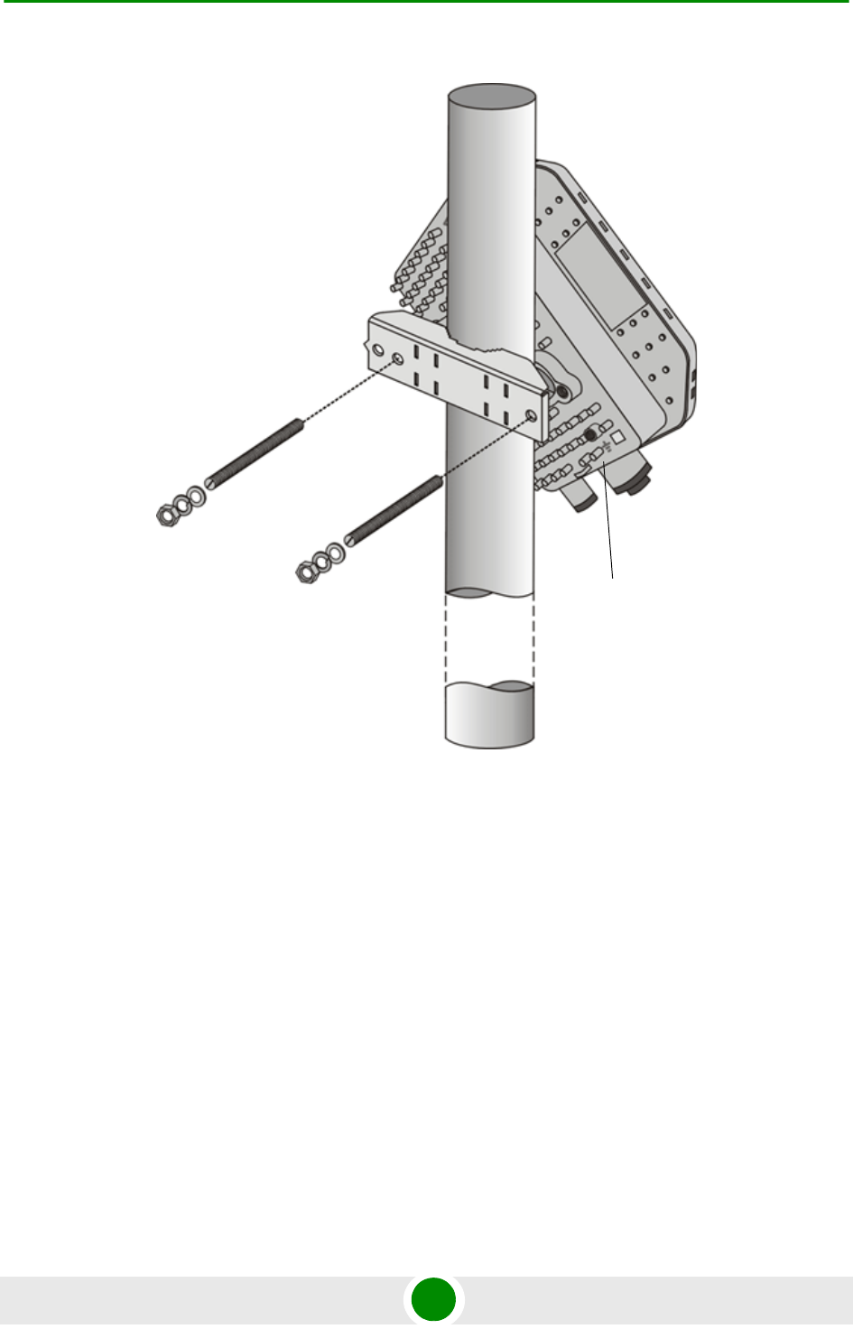
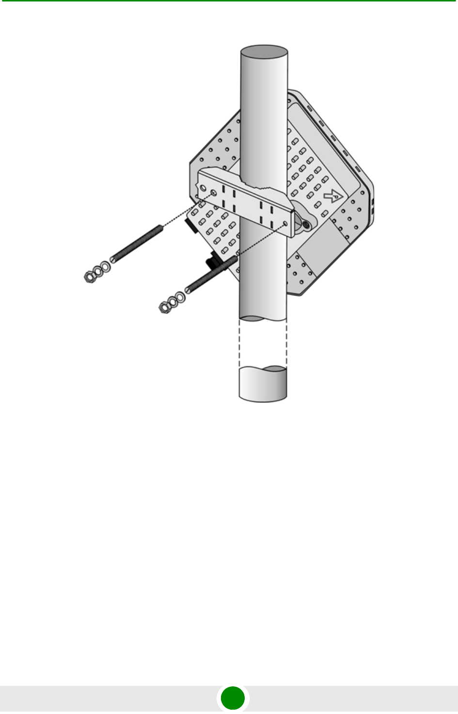
2.1.4.1 Pole Mounting the ODU Using the Clamp
Figure 2-1 and Figure 2-2 illustrate how to mount an ODU on a pole, using the
clamp and threaded rods.
NOTE
There is a groove on one end of the threaded rod. Insert the rods with the grooves pointing outward,
and fasten them to the unit using a screwdriver.Install the unit with the bottom panel, which includes
the connectors, facing downward.
NOTE
You can install the ODU with the arrow on the back of the unit facing upwards or rightwards. Make
sure that the connectors are facing downwards.
Chapter 2 - Installation Installing the ODU of the PRO CPE
BreezeMAX PRO 5000 CPE 17 Product Manual
Figure 2-1: ODU Pole Installation Using the Special Clamp, Arrow Facing Upwards
Grounding
screw
Chapter 2 - Installation Installing the ODU of the PRO CPE
BreezeMAX PRO 5000 CPE 18 Product Manual
Figure 2-2: ODU Pole Installation Using the Special Clamp, Arrow Facing Rightwards
Chapter 2 - Installation Installing the ODU of the PRO CPE
BreezeMAX PRO 5000 CPE 19 Product Manual
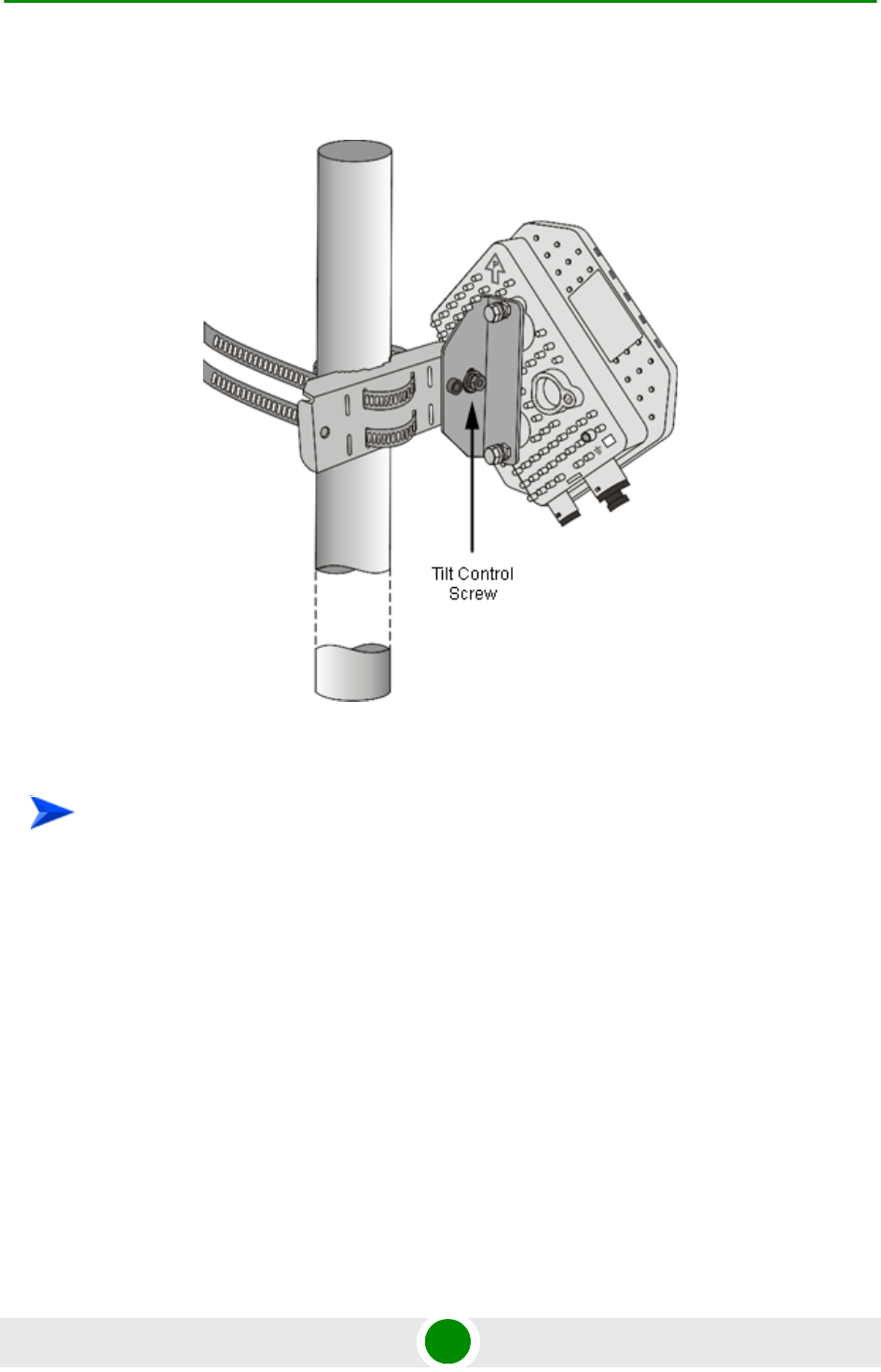
2.1.4.2 Pole Mounting the ODU with the Tilt Accessory
1Attach the Tilt accessory to the ODU using the two pairs of flat washers, spring
washers and nuts supplied in the Tilt kit.
2Mount the Tilt accessory on a 1" to 4" pole using two 9/16" metal bands.
3Release slightly the Tilt Control Screw, tilt the ODU downward/upward as
required, and re-tighten the screw.
Figure 2-3: ODU Pole Installation Using the Tilt Accessory, Vertical Polarization
To mount the ODU on a pole using the Tilt accessory:
Chapter 2 - Installation Installing the ODU of the PRO CPE
BreezeMAX PRO 5000 CPE 20 Product Manual
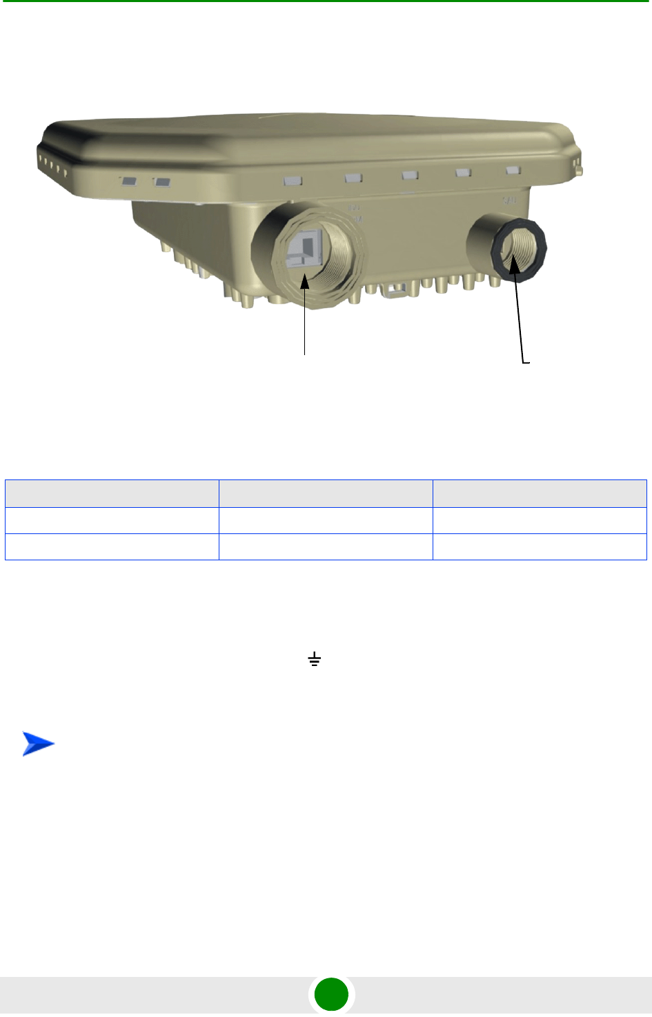
2.1.5 Connectors
2.1.6 Connecting the Cables
2.1.6.1 Connecting the Grounding Cable
The Grounding screw (marked ) is located on the back panel of the ODU (see
Figure 2-1).
1Connect one end of a grounding cable to the grounding screw and tighten the
grounding screw firmly.
2Connect the other end of the grounding cable to a good ground (earth)
connection.
Figure 2-4: Bottom Panel of the ODU (without sealing covers)
Table 2-2: CPE-ODU-PRO Connectors
Name Connector Functionality
IDU COM 10/100Base-T (RJ-45) Connection to the IDU
SAU Special mini USB Connection to SAU
To connect the grounding cable:
IDU COM SAU Port

Chapter 2 - Installation Installing the ODU of the PRO CPE
BreezeMAX PRO 5000 CPE 21 Product Manual
2.1.6.2 Connecting the IDU-ODU Cable
Use a crimp tool for RJ-45 connectors to prepare the wires. Insert them into the
appropriate pins and use the tool to crimp the connector. Make sure to do the
following:
Remove as small a length as possible of the external jacket. Verify that the
external jacket is well inside the sealing cover when connected to the unit, to
ensure good sealing.
Pull back the shield drain wire before inserting the cable into the RJ-45
connector, to ensure a good connection with the connector's shield after
crimping.
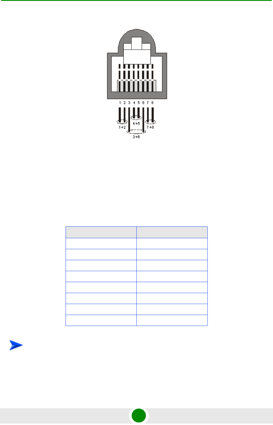
The IDU-ODU cable provides pin-to-pin connection on both ends.
The following figure shows the required wire pair connections.
CAUTION
Use only Category 5E 4x2x24# FTP outdoor cables from an approved manufacturer. See list of
approved cables in Table 2-1.The length of the Indoor-to-Outdoor cable should not exceed 90
meters. The length of the Indoor-to-Outdoor cable, together with the length of the Ethernet cable
connecting the CPE-IDU-1D to the data equipment, should not exceed 100 meters.
To prepare the IDU-ODU cable:
Chapter 2 - Installation Installing the ODU of the PRO CPE
BreezeMAX PRO 5000 CPE 22 Product Manual
Data pairs are 1&2, 3&6.
Power pair (proprietary solution) is 4&5.
The color codes used in standard cables supplied by Alvarion are as listed in the
following table:
Figure 2-5: Ethernet Connector Pin Assignments
Table 2-3: Cable Color Codes
Wire color Pin
Blue 1
Blue/white 2
Orange 3
Orange/white 6
Brown 4
Brown/white 5
Green 7
Green/white 8
To connect the IDU-ODU cable:
Chapter 2 - Installation Installing the ODU of the PRO CPE
BreezeMAX PRO 5000 CPE 23 Product Manual
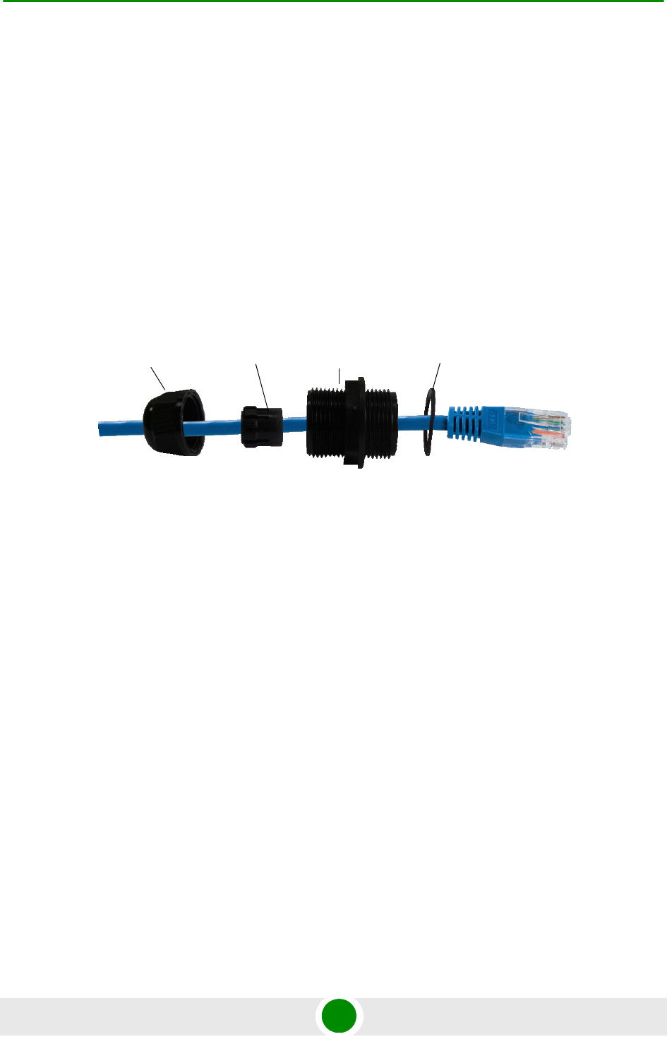
1The seal has a special groove allowing to insert an ethernet cable with an
already assembled RJ-45 connector. Strip the cable sheath and crimp the
RJ-45 plug.
2Insert the cable with the assembled connector through the sealing nut.
3To expose the groove, lightly squeeze the seal. Carefully insert the cable
through the groove.
4Insert the cable through the housing and insert the seal at the back end of the
housing.
5Tighten the sealing nut onto the housing.
6Stricken the gasket on the front end of the housing.
7Connect the Ethernet cable to the IDU COM RJ-45 connector and tighten the
sealing cap.
8Route the cable to the location selected for the indoor equipment.
9Assemble an RJ-45 connector with a protective cover on the indoor end of the
IDU-ODU cable. Refer to the pin assignment and color codes in standard
cables described above.
Figure 2-6: Inserting the IDU COM Cable into the Sealing Cap
Seal Housing Gasket
Sealing nut

Chapter 2 - Installation Installing the IDU-1D Indoor Unit of the PRO 5000 CPE
BreezeMAX PRO 5000 CPE 24 Product Manual
2.2 Installing the IDU-1D Indoor Unit of the
PRO 5000 CPE
2.2.1 Installation Requirements
2.2.1.1 Packing List
BMAX-CPE-IDU-1D
Wall mounting kit
2.2.1.2 Additional Installation Requirements
Ethernet cable(s): a crossed cable if connecting to a hub/switch and a straight
cable if connecting directly to a PC Network Interface Card (NIC).
Mains power cord
Mains plug adapter or termination plug (if the power plug on the supplied AC
power cord does not fit local power outlets).
For configuring parameters: a Portable PC/Notebook and a straight Ethernet
cable for configuring parameters using a web browser.
Other installation tools and materials (a drill for wall-mounting the unit,
means for securing cables to walls, etc.)
2.2.2 Location
The unit can be placed on a desktop or a shelf. Alternatively, it can be
wall-mounted using the mounting kit and guidelines supplied with the unit.
NOTE
The length of the Ethernet cable connecting CPE-IDU-1D to the user's equipment, together with the
length of the IDU-ODU cable, should not exceed 100 meters.
Chapter 2 - Installation Installing the IDU-1D Indoor Unit of the PRO 5000 CPE
BreezeMAX PRO 5000 CPE 25 Product Manual
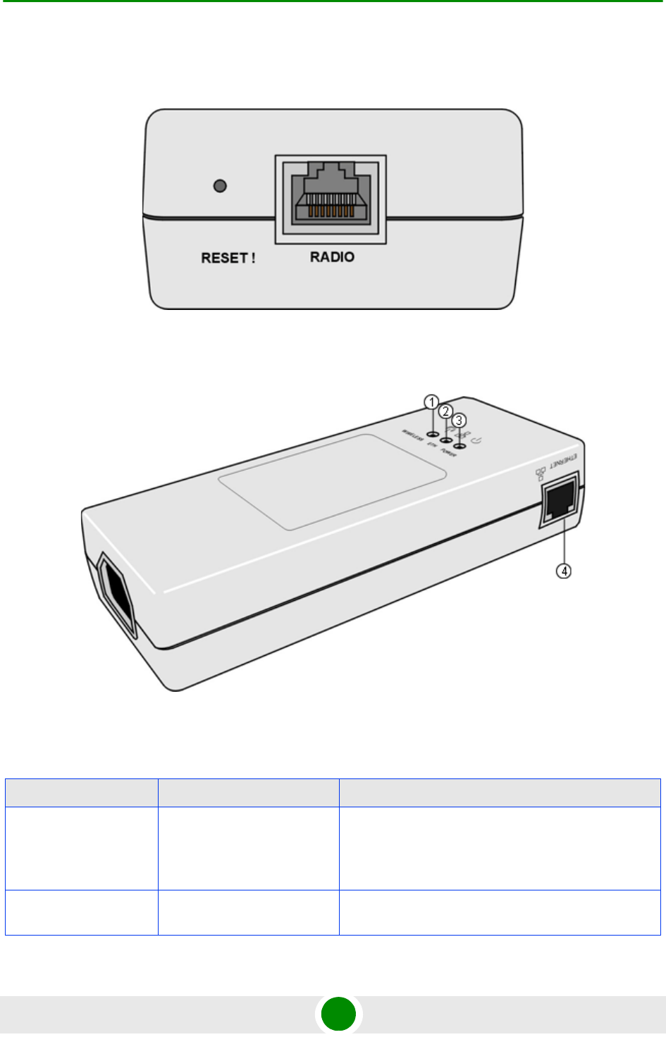
2.2.3 CPE IDU-1D Connectors and LEDs
Figure 2-7: CPE-IDU-1D Front Panel
Figure 2-8: CPE-IDU-1D 3D View
Table 2-4: CPE-IDU-1D Connectors
Name Connector Functionality
ETHERNET (4)
(on the side panel)
10/100Base-T (RJ-45) with 2
embedded LEDs
Connection to the user's LAN/PC
Cable connection to a hub/switch/router: Crossed
Cable connection to a PC: Straight
RADIO
(on the front panel)
10/100Base-T (RJ-45) Connection to the ODU

Chapter 2 - Installation Installing the IDU-1D Indoor Unit of the PRO 5000 CPE
BreezeMAX PRO 5000 CPE 26 Product Manual
* After power-up, the WIRELESS LED illuminates until self-test is finished.
2.2.4 RESET Button
The recessed RESET button is located on the front panel of the unit. When
pressed, power to the ODU is disconnected (hard reset).
2.2.5 IDU Installation
1It is assumed that the IDU-ODU cable is already connected to the ODU.
Assemble an RJ-45 connector with a protective cover on the indoor end of the
IDU-ODU cable. Refer to Section 2.1.6.2 for instructions on preparing the
cable.
2Connect the IDU-ODU cable to the RADIO connector. The RADIO connector in
the CPE-IDU-1D is located on the front panel as shown in Figure 2-7.
POWER
(on the bottom panel)
3-pin AC Mains power connection
Table 2-5: CPE-IDU-1D LEDs
Name Description Functionality
POWER (3) Power Indication Off - IDU is not powered or power failed
Green - IDU power is OK
ETH (2) Ethernet link status
(Ethernet integrity)
Off - No Ethernet connectivity has been detected between
the outdoor unit and the device connected to the indoor
unit’s data port
Green - Ethernet connectivity has been detected between
the outdoor unit and the device connected to the indoor
unit’s data port
WIRELESS (1) Wireless link status Off - SU is not associated with a BS
Green - SU is connected with a BS (network entry
completed)
Blinking Green - Authentication failed
To install the IDU:
Table 2-4: CPE-IDU-1D Connectors
Name Connector Functionality
Chapter 2 - Installation Installing the IDU-1D Indoor Unit of the PRO 5000 CPE
BreezeMAX PRO 5000 CPE 27 Product Manual
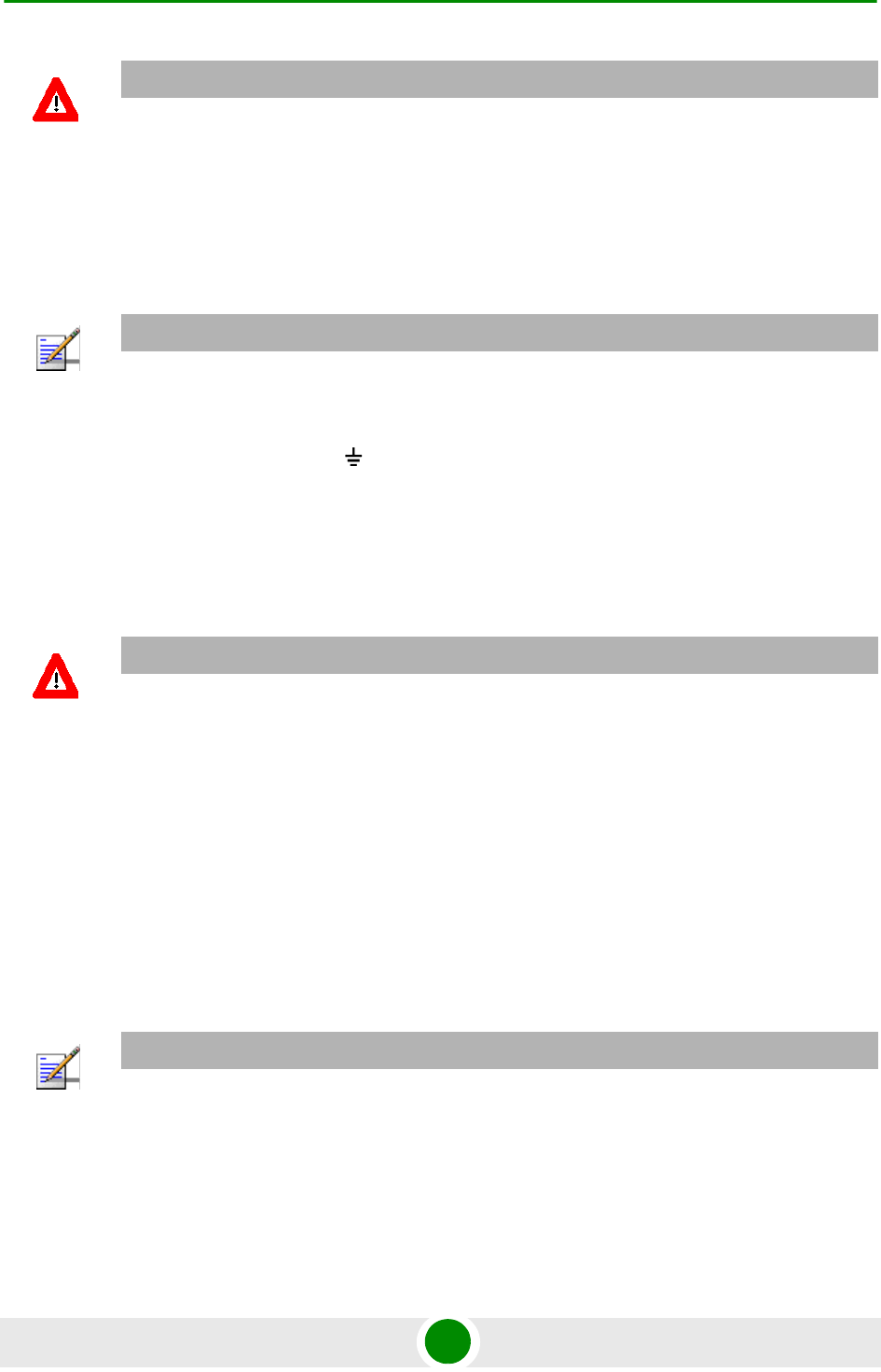
3Connect the power cord to the unit's AC socket, located on the rear panel.
Connect the other end of the power cord to the AC mains after verifying that
the unit is rated for the voltage in the country of use; the AC range is indicated
on the back side of the CPE-IDU-1D.
4To comply with safety regulations, the shield of the ODU-IDU outdoor-rated
Ethernet cable must be connected to protective ground (earth). The grounding
point can be either inside the building, or immediately at the entry point to the
building, depending on where a protective ground is available.
5Verify that the POWER LED located on the front panel is lit, indicating that the
unit is supplying power to the radio port.
6Configure the basic parameters and align the antenna as described in the
applicable sections of Chapter 3.
7Connect the 10/100 Base-T ETHERNET connector(s) to the data equipment.
The cable connection should be a crossed Ethernet if connecting to a
hub/switch and a straight cable if connecting directly to a PC Network
Interface Card (NIC).
8Verify proper operation as described in the applicable section of Chapter 3.
CAUTION
Do not connect the data equipment to the RADIO port. The RADIO port supplies DC power to the
ODU, and this may harm other equipment connected to it.
NOTE
The color codes of the power cable are as follows:
Brown Phase ~
Blue Neutral 0
Yellow/Green Ground
CAUTION
Grounding the ODU-IDU Ethernet cable must be performed by a professional installer in
conformance with local safety regulations.
NOTE
The length of the Ethernet cable connecting CPE-IDU-1D to the user's equipment, together with the
length of the IDU-ODU cable, should not exceed 100 meters.
Chapter 2 - Installation Installing the IDU-1D Indoor Unit of the PRO 5000 CPE
BreezeMAX PRO 5000 CPE 28 Product Manual
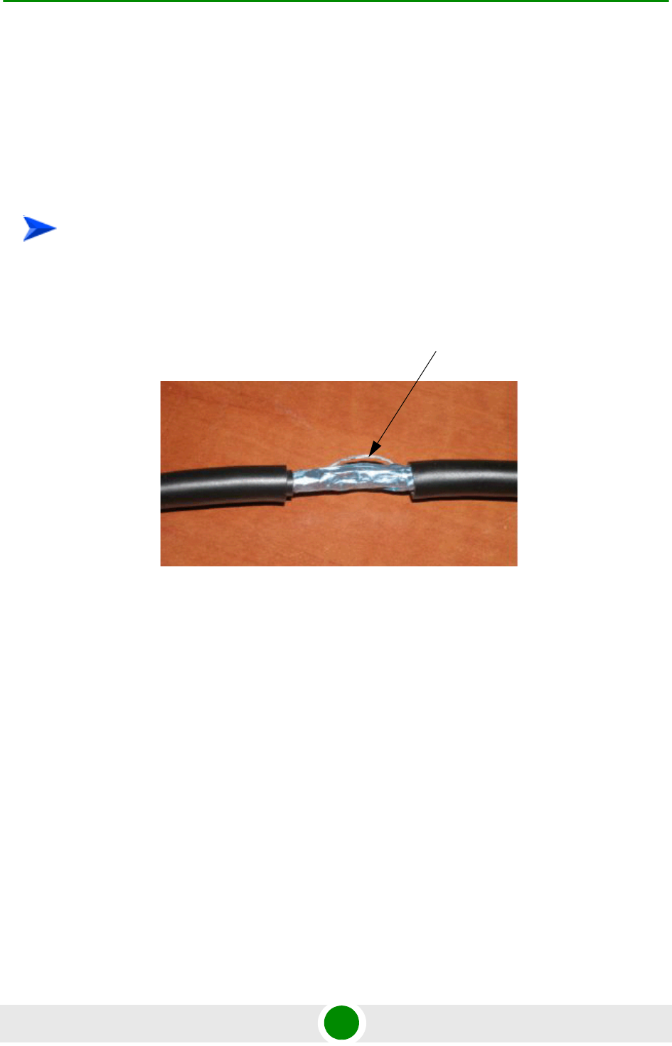
2.2.6 Grounding the ODU-IDU Cable
Follow the instructions below to ground the ODU-IDU cable. The following
paragraphs describe one method for grounding the outdoor-rated Category 5E
Ethernet cable through its drain wire. The actual connection method employed
is left to the professional installer.
1Strip back about a one inch (2.4 cm) section of the Ethernet cable jacket to
expose the drain wire.
2Attach a grounding cable to the drain wire and then connect it to protective
earth.
3Use weatherproof tape to cover and seal the attachment area on the Ethernet
cable.
To ground the ODU-IDU Ethernet cable, follow these steps:
Drain Wire

3
Chapter
Commissioning


Chapter 3 - Commissioning Commissioning Steps
BreezeMAX PRO 5000 CPE 31 Product Manual
3.1 Commissioning Steps
After completing the installation process, as described in the preceding chapter,
several actions should be performed to ensure connectivity with a BTS and
provisioning of services. After the SU is connected with a BTS, it can be fully
managed via the wireless link:
1The basic parameters must be configured to ensure that the unit operates
correctly and can communicate with a BTS.
2The antenna must be aligned to ensure optimal performance of the wireless
link.
3Proper operation should be verified, including data connectivity.

Chapter 3 - Commissioning Configuring Basic Parameters
BreezeMAX PRO 5000 CPE 32 Product Manual
3.2 Configuring Basic Parameters
3.2.1 The Basic Parameters
Table 3-1: SU's Basic Parameters
Parameter Default Value Comment
Ethernet Port auto Negotiation
Enable/Disable
Enabled
Ethernet Port Speed and Duplex Applicable only if Ethernet Auto
Negotiation Enable/Disable is set to do
Disable
User Name CPEMACaddress@WiMax.com Should be supplied by system
administrator/operator
User Password Empty Should be supplied by system
administrator/operator
Organization Empty
Address Empty
Country Empty
BST/AU ID 0.0.0.0.0.0
BST/AU ID Mask 0.0.0.0.0.0
Preferred BST/AU ID 0.0.0.0.0.0
Preferred BST/AU ID Mask 0.0.0.0.0.0
Bandwidth Auto (5/10 MHz)
Start Rx Frequency (KHz) Depends on Radio Band and
Bandwidth
End Rx Frequency (KHz) Depends on Radio Band and
Bandwidth
Scanning Main Step 2.5 MHz
Discrete Scanning Frequencies Null (empty list)
NOTE
Most parameters are changed to their new values only after reset (refer to Section 4.14 for more
details). Once the basic parameters are configured, the unit should be reset in order to activate the
new configuration.
Chapter 3 - Commissioning Configuring Basic Parameters
BreezeMAX PRO 5000 CPE 33 Product Manual
3.2.2 Configuration Tools
The SUs include a Web Configuration Server, providing a web-based GUI for local
configuration and monitoring. The Web Configuration Server can be accessed
using a PC/Notebook with a web browser.
The SU may be delivered with the operator’s default settings already configured in
the FLASH memory. If there is need to change these settings then the only
parameters that should be configured are the end user’s credentials (User Name
and User Password).
3.2.3 Using the Web Configuration Server
1Connect a PC/Notebook with a web browser to the Ethernet port of the SU,
using a straight Ethernet cable.
2Configure the PC's IP parameters to enable connectivity with the unit. The IP
address of the SU for local management access is 192.168.254.251. The
Subnet Mask is 255.255.255.0. The recommended IP address for the PC is
192.168.254.250, as this is also the default TFTP Sever IP Address (required
for downloading SW versions and for downloading/uploading configuration
files).
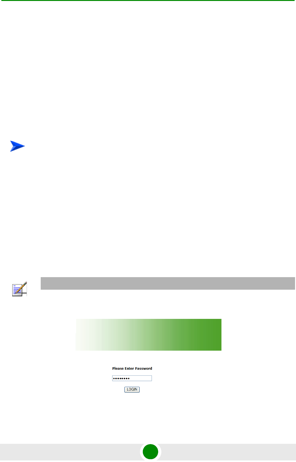
3Open a web browser, and connect to http://192.168.254.251. The “Enter the
Password” prompt is displayed. Enter the password and press the Enter key.
To configure the SU's basic parameters:
NOTE
The default password is "installer".
Figure 3-1: Login Window

Chapter 3 - Commissioning Configuring Basic Parameters
BreezeMAX PRO 5000 CPE 34 Product Manual
4The Main window of the Web Configuration Server is displayed, enabling
access to the required parameters configuration and performance monitoring
options. Refer to Chapter 4 for instructions on using the Web Configuration
Server and detailed information on the various parameters and other features
supported.
5Configure the basic parameters listed in Table 3-1.
6Reset the unit to apply the new settings and enable synchronization with a BS.
Chapter 3 - Commissioning Aligning the PRO CPE’s Antenna
BreezeMAX PRO 5000 CPE 35 Product Manual
3.3 Aligning the PRO CPE’s Antenna
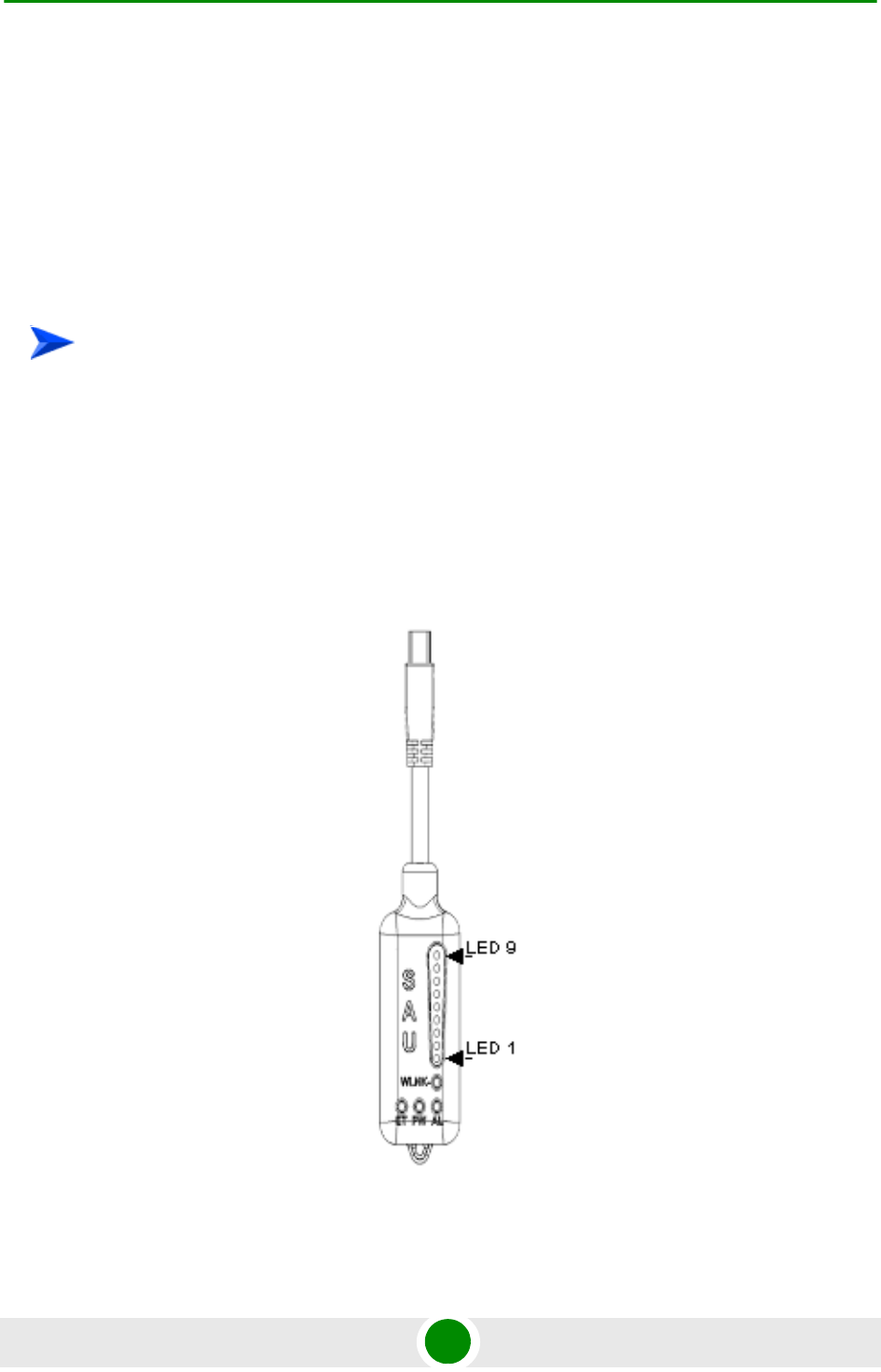
3.3.1 SU Alignment Unit (SAU)
The miniature SU Alignment Unit can be used during installation and testing to
support an easy process of antenna alignment and provide the ODU's status
indications.
1Remove the sealing cap of the ODU's SAU connector.
2Connect the cable attached to the SAU to the SAU connector.
3After completing the installation, disconnect the cable and replace the cap.
Use appropriate sealing material to protect the connection against moisture and
humidity. Use removable sealing material, such as a tar seal, to enable future
access to the connector.
To connect the SAU to the ODU:
Figure 3-2: SAU

Chapter 3 - Commissioning Aligning the PRO CPE’s Antenna
BreezeMAX PRO 5000 CPE 36 Product Manual
* After power-up of the ODU, the all LEDs illuminate until self-test has completed.
Table 3-2: SAU LEDs
Name Description Functionality
AL Alarm indication Off - ODU is OK, diagnostic test passed
Red - ODU failure
PW Power indication Off - ODU is not powered or 3.3 VDC failure
Green - ODU power to SAU is OK
ET Ethernet link status
indication
(Ethernet integrity)
Off - No Ethernet connectivity has been
detected between the outdoor unit and the
device connected to the indoor unit’s
Ethernet port
Green- Ethernet connectivity has been
detected between the outdoor unit and the
device connected to the indoor unit’s
Ethernet port
WLNK Wireless link status
indication
Off - The SU is not connected with a BS
Orange on - The SU is connected with and
receives services from the BS (Network
Entry completed). Link Quality is indicated
by LEDs 1-9 as described in Table 3-3.
below.
Blinking orange - Authentication failed
(LEDs 6, 7 and 8 on)

Chapter 3 - Commissioning Aligning the PRO CPE’s Antenna
BreezeMAX PRO 5000 CPE 37 Product Manual
3.3.2 Using SAU for Aligning the PRO CPE's
Antenna
The LINK QUALITY bar display on the SAU comprises 9 LEDs:
The WLNK LED indicates that the wireless link is active, and is lit when the SU
has completed the Network Entry process.
LEDs 1 to 8 (green) and 9 (red) indicate the quality of the received signal. The
higher the number of LEDs illuminating, the better the quality of the received
signal.
If all LEDs, including LED 9 (red) are on, the received signal strength is too
high. This must be avoided, preferably by up-tilting the antenna. As a rule of
thumb, if the SU is located at a distance of less than 300 meters from the BTS,
it is recommended to up-tilt the antenna by approximately 10° to 15°.
Table 3-3: SAU LINK QUALITY LEDs Functionality
Bar LEDs SNR
LED 1 (green) is On Wireless link is established.
LED 2 (green) is On 5dB SNR < 9dB
LEDs 2-3 (green) are On 10dB SNR < 14dB
LEDs 2-4 (green) are On 15dB SNR < 19dB
LEDs 2-5 (green) are On 20dB SNR < 23dB
LEDs 2-6 (green) are On SNR 24dB and RSSI < -72dBm
LEDs 2-7 (green) are On SNR 24dB and RSSI -72dBm
LEDs 2-8 (green) are On SNR 24dB and RSSI -69dBm
LEDs 2-9 (green) are On SNR 24dB and RSSI -60dBm
LEDs 2-10 (green) and 9 (red) are On RSSI -21dBm (saturation)
LEDs 2-10 Blinking one after the other During full frequency scan
LEDs 2-10 Blinking as follows: LED 6 lights, after 200ms
LEDs 7 & 5 light, after 200ms LEDs 8 & 4 light, after 200ms
LEDs 9 & 3 light, after 200ms LEDs 10 & 2 light, after 200ms
all the LEDs are extinguished and then the sequence is
repeated.
During Best AU selection process or short scan
To align the antenna:

Chapter 3 - Commissioning Aligning the PRO CPE’s Antenna
BreezeMAX PRO 5000 CPE 38 Product Manual
1Point the antenna toward the general direction of the BTS.
2Connect the SAU to the ODU.
3Verify that the PWR (power) indication on the SAU is on.
4Verify that the WLNK LED indicator is on, indicating that the unit is
synchronized with a BS. If the SU is not synchronized with a BS, ensure that
all parameters are configured properly. If the unit is still not synchronized with
a BS, improve the quality of the link by changing the direction of the antenna
or by placing the antenna at a higher point or in an alternate location.
5Rotate (and/or tilt if applicable) the ODU until the maximum link quality
reading is achieved. If you encounter prolonged difficulty in achieving the
expected link quality, try to improve the reception quality by placing the ODU
at a higher point or in an alternate location.
6Secure the ODU firmly to the pole.
NOTE
Ensure that the front of the antenna is always facing the BTS. However, in certain conditions, such
as when the line of sight to the BTS is hampered, better reception may be achieved using a
reflected signal. In this case, the antenna is not necessarily directed toward the BTS.

Chapter 3 - Commissioning Operation Verification
BreezeMAX PRO 5000 CPE 39 Product Manual
3.4 Operation Verification
To verify proper operation of the PRO CPE, examine the LED indicators on the IDU
(see Table 2-5) and the SAU (see Table 3-2).
To verify proper connection to the end-user's data equipment, examine the
Ethernet Integrity and Ethernet Activity LEDs of the Ethernet connectors.
To verify data connectivity, from the end-user's PC or from a portable PC
connected to the unit, ping a known device in the network, or connect to the
Internet.
NOTE
Verifying the correct operation of the ODU using the SAU LEDs is meaningful only after the
configuration and alignment processes are completed, and the unit is synchronized with a BS.

4
Chapter
Operation

Chapter 4 - Operation
BreezeMAX PRO 5000 CPE 41 Product Manual
In This Chapter:
“Introduction to SU Management” on page 42
“Accessing the Web Configuration Server” on page 43
“Using the Web Configuration Server” on page 44
“Show All” on page 45
“Unit Control Parameters” on page 46
“Registration Parameters” on page 57
“BST/AU Parameters” on page 61
“Radio Parameters” on page 65
“ATPC Parameters” on page 70
“Performance Monitor” on page 73
“Service Parameters” on page 77
“Management Parameters” on page 79
“Logout” on page 80
“Parameters Summary” on page 81

Chapter 4 - Operation Introduction to SU Management
BreezeMAX PRO 5000 CPE 42 Product Manual
4.1 Introduction to SU Management
The units support the TR-069 CPE WAN Management Protocol (CWMP), allowing
efficient management by an Auto Configuration Server (ACS).
In addition, configuration and performance monitoring of a single unit can be
performed either locally (via the Ethernet port) or remotely using any of the
following options:
Using a PC/Notebook with an http browser to access the built-in web
configuration server.
Using TFTP to upload/download a Configuration File.
For local management, the management IP address is 192.168.254.251 with
subnet mask 255.255.255.0.
Remote (over the air) management is done using a WAN management IP address
acquired from a DHCP server as a part of the Network Entry process. The DHCP
server should supply also the IP address of the ACS management station. Remote
management service is always in IP CS service mode (even if the unit uses
Ethernet CS for regular services). In the uplink, the DSCP value of management
packets sent by the unit can be configured only by the remote management
system using TR-069 (the default is 6). In downlink management packets the
DSCP value is ignored.
The Web Configuration Server enables the configuration of all SU parameters
using a Notebook/PC with a web browser. It also enables downloading of SW files,
control of the running SW version, and downloading/uploading of the
configuration file, enabling simplified and faster configuration process.
The Web Configuration Server also provides a selection of performance monitoring
capabilities, allowing installers and technicians to view information on link quality
and traffic counters. These monitoring capabilities enable performance
verification and problems identification.
To further support local testing, the program also enables temporary control of the
ATPC mechanism.

Chapter 4 - Operation Accessing the Web Configuration Server
BreezeMAX PRO 5000 CPE 43 Product Manual
4.2 Accessing the Web Configuration Server
To configure parameters using the Web Configuration Server, connect a
PC/Notebook with a web browser to the Ethernet port of the IDU, using a straight
Ethernet cable.
1Configure the PC's IP parameters to enable connectivity with the unit. The IP
address of the SU for local management access is 192.168.254.251. The
Subnet Mask is 255.255.255.0. The recommended IP address for the PC is
192.168.254.250, as this is also the default TFTP Sever IP Address (required
for downloading SW versions and for downloading/uploading configuration
files).
2Open a web browser, and connect to http://192.168.254.251. The Enter
Network Password window is displayed. Enter the Username and password
and click OK.
3The Main window of the Web Configuration Server is displayed, enabling
access to the required parameters configuration and performance monitoring
options.
NOTE
The default password is "installer".
Figure 4-1: Web Configuration Server - Main Window

Chapter 4 - Operation Using the Web Configuration Server
BreezeMAX PRO 5000 CPE 44 Product Manual
4.3 Using the Web Configuration Server
The Web Configuration Server view when using a Notebook/PC consists of a
number of menu links (to the left). Clicking on each of them will display the
configuration/status page for the selected menu item, with the applicable content
(configurable parameters/options or status information) in the main area.
Several pages include a page selection bar at the top of the page, enabling
selection between several pages related to the same menu item.
Several pages include a Current Parameters area and a Configured Parameters
area. The Current Parameters area displays the current unit's settings. To change
the settings of the parameters, enter the new settings in the configuration field
and click the Update/Apply button. The change will appear in the Configured
Parameters area and will take effect after performing reset to the unit.
The Web Configuration Server includes the following Menus:
“Show All” on page 45
“Unit Control Parameters” on page 46
“Registration Parameters” on page 57
“BST/AU Parameters” on page 61
“Radio Parameters” on page 65
“ATPC Parameters” on page 70
“Performance Monitor” on page 73
“Service Parameters” on page 77
“Management Parameters” on page 79
“Logout” on page 80

Chapter 4 - Operation Show All
BreezeMAX PRO 5000 CPE 45 Product Manual
4.4 Show All
The Show All page enables viewing all the configurable parameters of the unit. In
addition, the displayed information includes the general hardware and software
properties of the units and relevant status details.
The display includes all the items available upon selecting the Show option for
specific groups of parameters.

Chapter 4 - Operation Unit Control Parameters
BreezeMAX PRO 5000 CPE 46 Product Manual
4.5 Unit Control Parameters
The Unit Control menu includes the following options:
Show
Reset Unit
Change Password
SW Versions Control
Configuration Control
TM/PM Files Control
Ethernet Op Mode
4.5.1 Show
Select this option to view the current values/selected option of applicable
parameters as well as general status information, as follows:
HW Details
»SU Type: CPE Pro SQ
»CPE Family: Describes the primary chipset of the CPE: Sequans
»Serial Number: Describes the serial number of the CPE unit. This number
can be used to determine the identity of the subscriber unit by the BTS
operator.
»MAC Address: This is the unit’s LAN MAC address. The WAN MAC address
is the displayed address +1.
»MAC Address Control Number (a number computed from the MAC Address
that can be used for verification purposes)
»Radio Band: Describes the radio band in use (currently only 5 GHz).
»HW Version: The version of the digital module

Chapter 4 - Operation Unit Control Parameters
BreezeMAX PRO 5000 CPE 47 Product Manual
»HW Configuration
»RF Version: The version of the radio module.
»SU Interface Type: 1D (one data port)
»Radio Type: the receive (Rx) and transmit (Tx) capacity of the radio. 1R/1T
- one receive (Rx) and one transmit (Tx).
»Antenna Type: Dual slant antenna (embedded)
Ethernet Port Operation Mode parameters and status:
»Ethernet Port Auto Negotiation Mode: Enable/Disable
»Ethernet Port Speed and Duplex
Operation Mode:
»IP CS - transparent delivery of IPv4 packets
»ETH CS transparent delivery of tagged 802.3 packets over Ethernet
Unit Status: the connectivity status of the unit. Possible statuses are:
»Searching for Base Station
»Base station found
»Not Authorized
»Not Registered
»Registered
SW Versions:
»SW Boot Version
»Main SW File Name
»Main SW Version
»Shadow SW File Name
Chapter 4 - Operation Unit Control Parameters
BreezeMAX PRO 5000 CPE 48 Product Manual
»Shadow SW Version
»Running from: Main or Shadow
Upload/Download Parameters:
»Local TFTP Server IP address: the IP address of the TFTP server from the
LAN side used for SW File/Configuration File download.
»Remote TFTP Server IP address: the IP address of the TFTP server from the
WAN side used for SW File/Configuration File download.
»SW File Name: the name in the TFTP server of the SW version to be
downloaded to the unit.
»Configuration File Upload Name: the name of the configuration file to be
uploaded.
»Configuration File Download Name: the name of the configuration file to be
downloaded.
»List of TM&PM Files gathered: the Traffic Monitoring (TM) and Performance
Monitoring (PM) files detected by the unit.
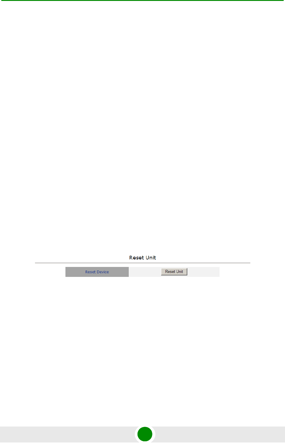
4.5.2 Reset Unit
The Reset Unit page enables to reset the unit. Click Reset Unit. To avoid
unintentional reset, you will be prompted to confirm the reset request. Changes to
most of the configurable parameters are applied only after reset. Refer to
Section 4.14 for information on which parameters are changeable in run time and
which changes are applied only after reset.
Figure 4-2: Reset Unit Page
Chapter 4 - Operation Unit Control Parameters
BreezeMAX PRO 5000 CPE 49 Product Manual
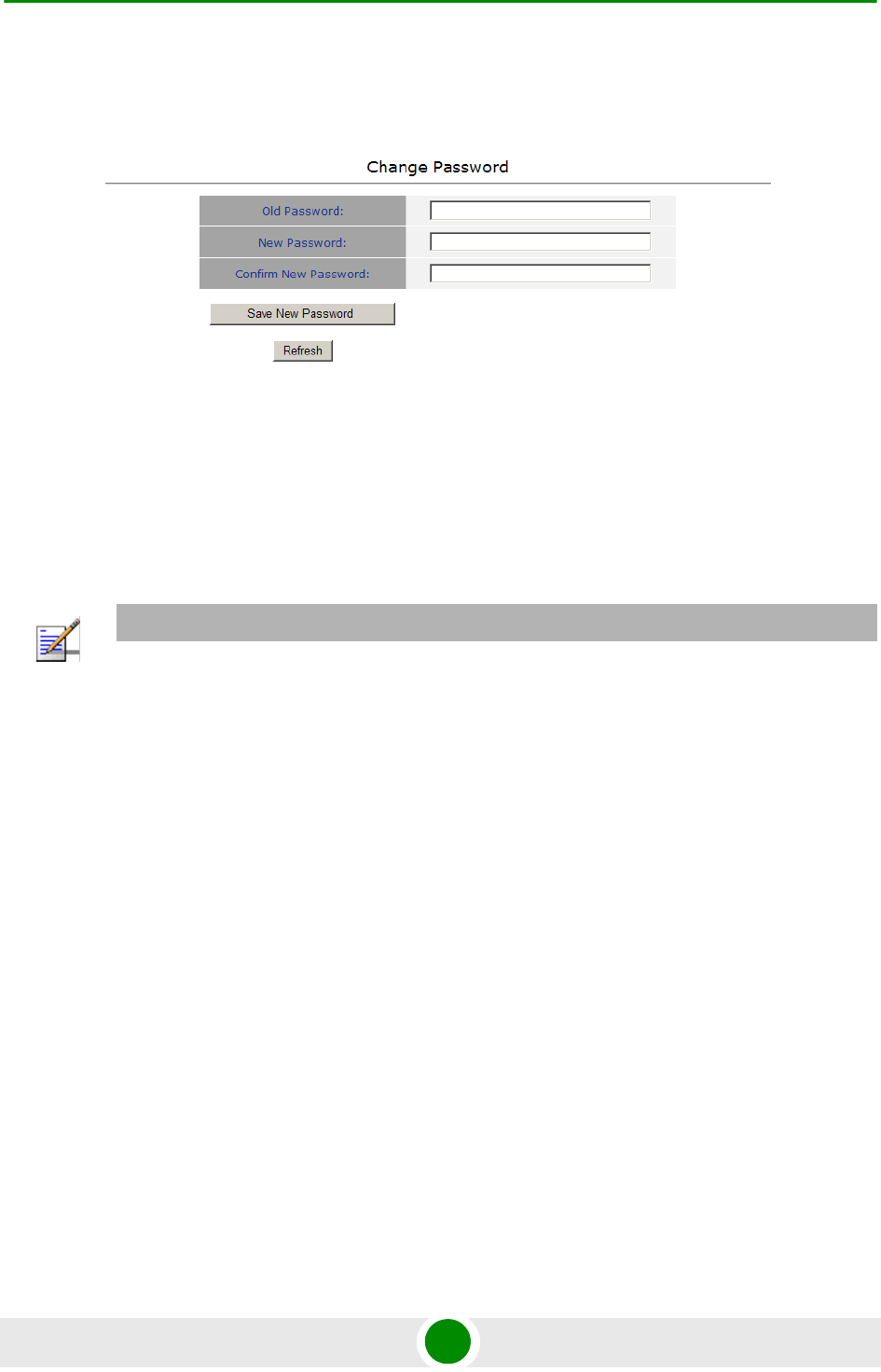
4.5.3 Change Password
The Change Password page enables to change the login password. Enter the old
password, the new password and re-enter the new password for confirmation.
Then click Save New Password.
Click Refresh to clear the fields.
Valid passwords: 1 to 20 printable characters, case sensitive.
Default password: installer
Figure 4-3: Change Password Page
NOTE
Notify the administrator of the new password!
Chapter 4 - Operation Unit Control Parameters
BreezeMAX PRO 5000 CPE 50 Product Manual
4.5.4 SW Versions Control
The SU can contain two SW versions:
Main: Normally, each time the SU resets it will reboot using the version
defined as Main.
Shadow: Normally the Shadow version is the backup version. Each time a new
SW File is downloaded to the SU, it will be stored as a Shadow version,
replacing the previous Shadow Version.
The typical process of upgrading to a new SW version includes the following steps:
1Download the new SW file to the SU. It will be stored as the Shadow version.
2Reset and run the unit from its Shadow version. Note that if the new SW file
was loaded from StarACS, the Run from Shadow operation will be performed
automatically.
3If the unit succeeded to complete network entry, the Shadow and Main
versions will be swapped automatically: The currently running version will be
defined as Main and will be used each time the unit reboots. The previous
version is defined now as Shadow.
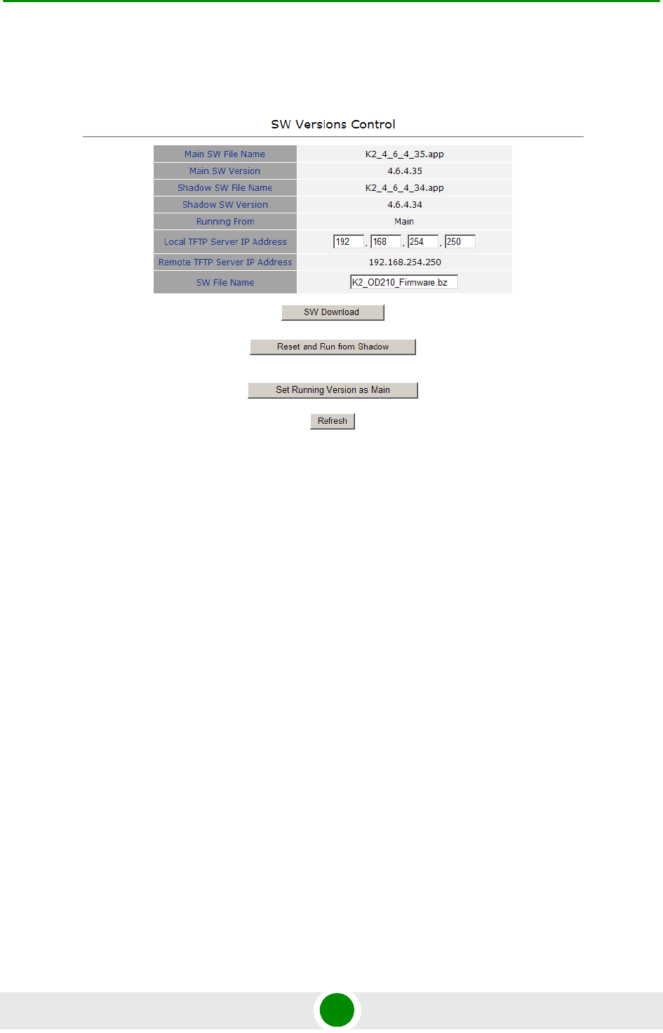
Figure 4-4: SW Versions Control Page

Chapter 4 - Operation Unit Control Parameters
BreezeMAX PRO 5000 CPE 51 Product Manual
The SU functions as a TFTP client, enabling the loading of SW files from a TFTP
server.
The SW Versions Control submenu includes the following fields:
Main SW File Name: the name of the Main software file.
Main SW Version: the version of the Main software.
Shadow SW File Name: the name of the software file in the shadow.
Shadow SW Version: the version of the software in the shadow.
Running From: indicates whether the unit is currently running the Main or
the Shadow version.
Local TFTP Server IP address: the IP address of the TFTP server from the LAN
side used for SW version download. The default TFTP Server IP address is
192.168.254.250. You can enter a new TFTP Server IP address.
Remote TFTP Server IP address: the IP address of the WAN TFTP server used
for SW version download.
SW File Name: the name in the TFTP server of the SW version file to be
downloaded to the unit.
The SW Versions Control submenu includes the following control buttons:
SW Download: click to execute the SW download operation. To avoid
unintentional actions you will be prompted to confirm the request. To perform
the SW download:
1The required SW file should be available in the TFTP Server directory in a
PC connected to the unit.
2Typically it is recommended to configure the IP address of the PC to
192.168.154.250, which is the default TFTP Server IP address of the unit.
NOTE
The same TFTP Server IP Address parameter is used in the SW Download, Configuration File
Download and Configuration File Upload processes.
Chapter 4 - Operation Unit Control Parameters
BreezeMAX PRO 5000 CPE 52 Product Manual
If a different IP address is configured in the PC with the TFTP, configure the
TFTP Server IP Address to the same address.
3Enter the name of the SW file (as called in the TFTP server) as the SW File
Name.
4Select Perform SW Download and confirm the download request. Wait to
receive a success/failure message.
5Following a successful download, the loaded SW version becomes the
Shadow version in the unit.
Reset and Run from Shadow: select this option to reset the unit and run the
Shadow version after power up. To avoid unintentional actions you will be
prompted to confirm the request.
Set Running Version as Main: when the unit is running the Shadow version
(after selecting Reset and Run from Shadow) without succeeding to complete
network entry, the versions will not be swapped and the unit will boot from the
Main version after the next reset. Select this option if you want to swap
versions so that the running version will become the Main version and will be
the version to be used after reset. To avoid unintentional actions you will be
prompted to confirm the request.
Refresh: select this option to clear the fields.
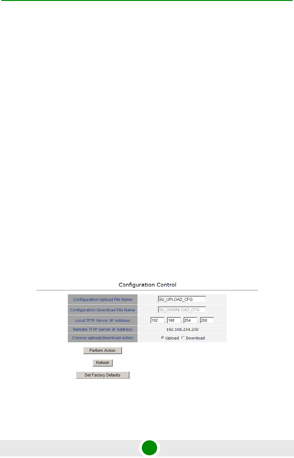
4.5.5 Configuration Control
Figure 4-5: Configuration Control Page
Chapter 4 - Operation Unit Control Parameters
BreezeMAX PRO 5000 CPE 53 Product Manual
The Configuration Control Submenu enables to define parameters related to
uploading/downloading of configuration files to/from the SU, and to initiate the
upload/download operation. The Configuration Control page includes the
following fields:
Configuration Upload File Name: enter the name in the TFTP server directory
of the configuration file to be uploaded. A Configuration File Upload Name
consists of up to 50 characters. The default Configuration File Upload Name is
SU_UPLOAD_CFG.
Configuration Download File Name: enter the name in the TFTP server of the
required configuration file. A Configuration File Download Name consists of up
to 50 characters. The default Configuration File Download Name is
SU_DOWNLOAD_CFG.
Local TFTP Server IP Address: enter the IP address of the LAN TFTP server. The
default TFTP Server IP address is 192.168.254.250.
Remote TFTP Server IP Address: enter the IP address of the WAN TFTP server.
The default TFTP Server IP address is 192.168.254.250.
Choose Upload/Download Action: select the action to perform, either upload
or download.
1Typically it is recommended to configure the IP address of the PC to
192.168.254.250, which is the default TFTP Server IP address of the unit. If a
different IP address is configured in the PC with the TFTP server, configure the
TFTP Server IP address to the same address.
2Enter the name of the configuration file (as will appear in the TFTP server) in
the Configuration File Upload Name.
3Select Upload in the Choose Upload/Download Action field.
NOTE
The same TFTP Server IP Address parameter is used in the SW Download, Configuration File
Download and Configuration File Upload processes.
To perform configuration file upload:

Chapter 4 - Operation Unit Control Parameters
BreezeMAX PRO 5000 CPE 54 Product Manual
4Click Perform Action. To avoid unintentional actions you will be prompted to
confirm the request. Confirm the upload request and wait to receive a
success/failure message.
1The required configuration file should be available in the TFTP Server directory
in a PC connected to the unit.
2Typically it is recommended to configure the IP address of the PC to
192.168.154.250, which is the default TFTP Server IP address of the unit. If a
different IP address is configured in the PC with the TFTP server, configure the
TFTP Server IP address to the same address.
3Enter the name of the configuration file (as called in the TFTP server) as the
Configuration File Download Name.
4Select Download in the Choose Upload/Download Action field.
5Click Perform Action. To avoid unintentional actions you will be prompted to
confirm the request. Confirm the download request and wait to receive a
success/failure message.
6Following a successful download, reset the unit to apply the new
configuration.
The Configuration Control page includes the following control buttons:
Perform Action: executes the upload/download action.
Refresh: clears the screen.
Set Factory Defaults: click to reset the unit and revert to the default
configuration. To avoid unintentional actions you will be prompted to confirm
the request. All parameters except the Password will revert to the factory
default values.
4.5.6 TM/PM Files Control
Traffic and performance monitoring allow for a variety of statistical data to be
collected about the CPE and its WiMAX link. The TM (Traffic Monitoring) & PM
(Performance Monitoring) Files Control page enables the user to define parameters
related to uploading of TM & PM files where link quality data is stored, to the TFTP
server directory and to initiate the upload operation.
To perform configuration file download:
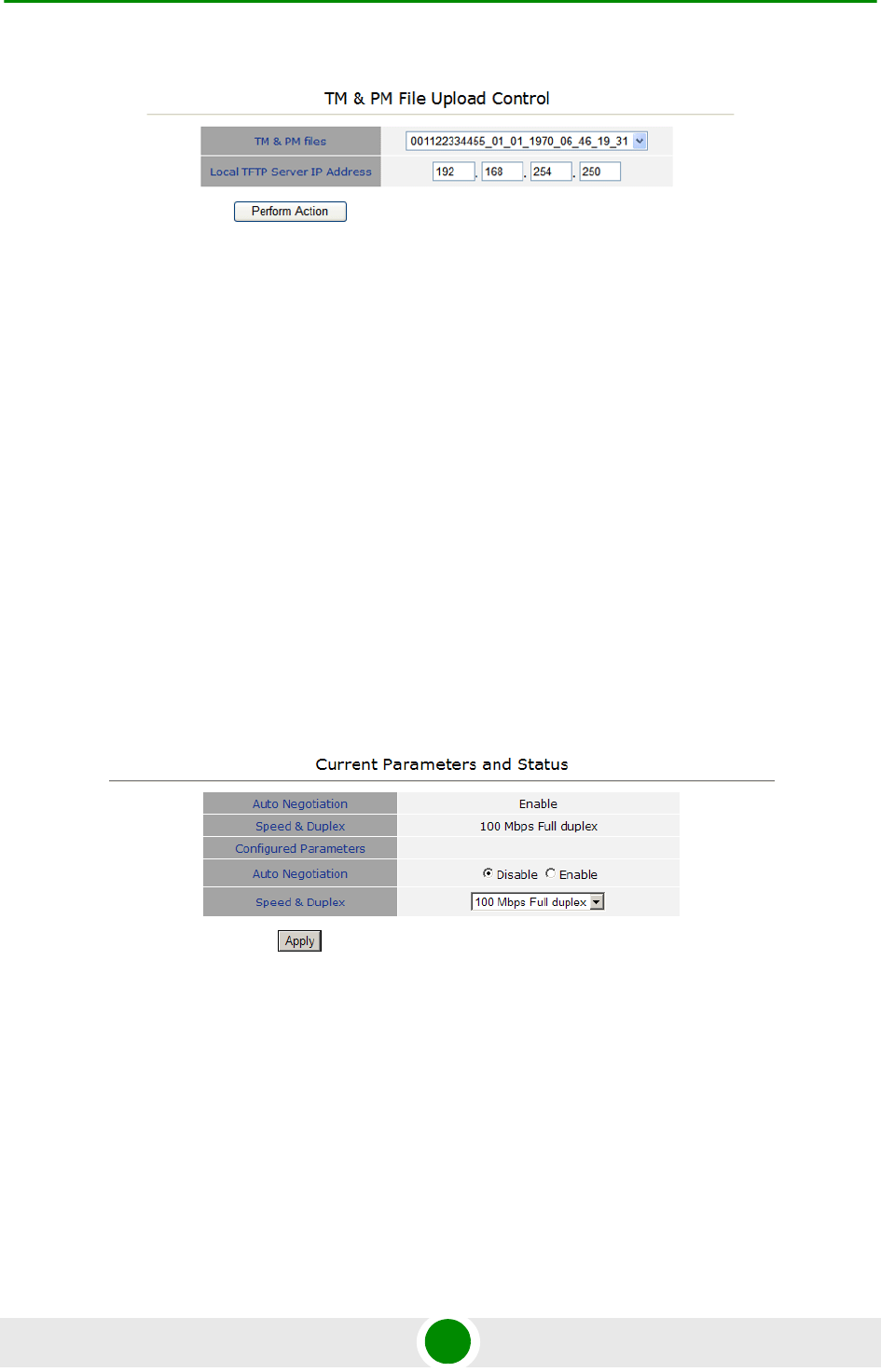
Chapter 4 - Operation Unit Control Parameters
BreezeMAX PRO 5000 CPE 55 Product Manual
The TM & PM File Upload Control page includes the following fields/buttons:
TM & PM Files: select from the available TM and PM files from the drop down
menu for uploading to the TFTP server.
Local TFTP Server IP Address: enter the local TFTP server IP address from
which to upload the TM and PM files.
Perform Action: click to initiate the upload procedure.
4.5.7 Ethernet Op Mode
The Ethernet Port control parameter enables viewing and defining the operation
mode of the Ethernet port.
The Ethernet Operation Mode page includes the following fields. The read-only
fields display the current configured parameters. The configurable fields enable to
set a different value for these parameters.
Auto Negotiation: enable/disable Auto Negotiation.
The default is Enable.
Figure 4-6: TM & PM File Upload Control Page
Figure 4-7: Ethernet Operation Mode Page

Chapter 4 - Operation Unit Control Parameters
BreezeMAX PRO 5000 CPE 56 Product Manual
Speed and Duplex: If Auto Negotiation is set to Enable, this field is greyed out.
If set to Disable, this parameters allows selecting one of the following options:
»10Mbps Half-Duplex
»10Mbps Full-Duplex
»100Mbps Half-Duplex
»100Mbps Full-Duplex
Click Apply to save the changes.
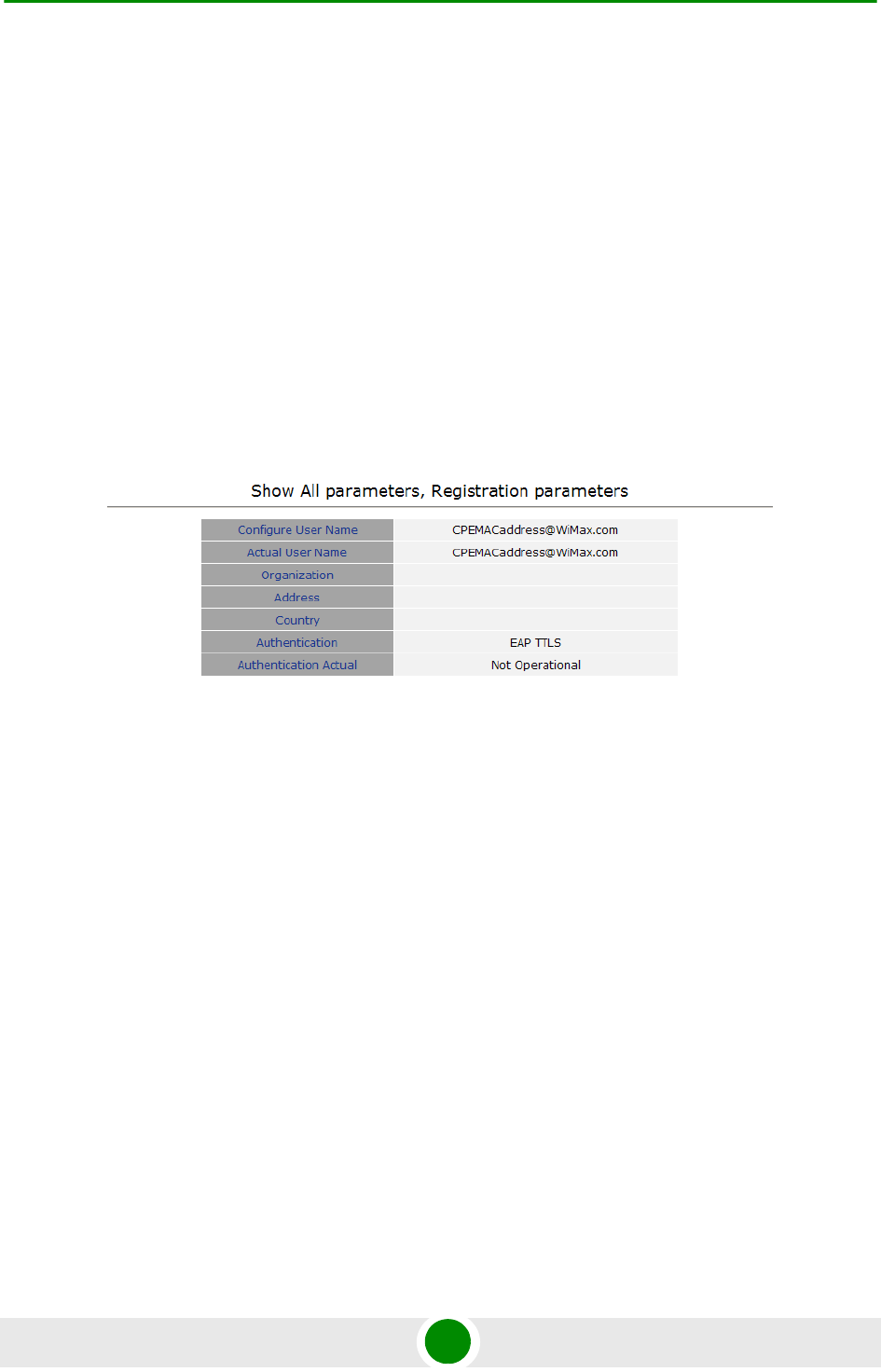
Chapter 4 - Operation Registration Parameters
BreezeMAX PRO 5000 CPE 57 Product Manual
4.6 Registration Parameters
The Registration menu includes the following sub-menus:
Show
Registration
4.6.1 Show
Select this submenu to view the registration parameters (excluding the User
Password that is not shown for security reasons).
User Name (Configured and Actual): the name of the unit, to be used for
service provisioning. Changes to the User Name parameter are applied only
after reset. Therefore, the actual value may differ from the configured value.
Both the actual and configured values are displayed.
Organization
Address
Country
Authentication: the method of authentication being used to secure the WiMAX
connection.
Authentication Actual: the status of the authentication:
Figure 4-8: Registration Show Page
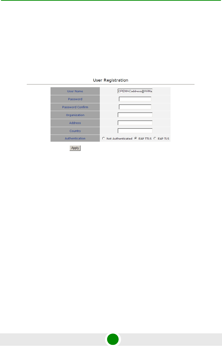
Chapter 4 - Operation Registration Parameters
BreezeMAX PRO 5000 CPE 58 Product Manual
»Rejected: the CPE’s authentication request was rejected.
»Authenticated: the CPE is connected to the BTS.
»Not Operational: no BTS is found.
4.6.2 Registration
The Registration page enables to set the following parameters. After setting the
parameters, click Apply. The changes are saved, and the Registration - Show page
is displayed. If reboot is required, a message is displayed at the bottom of the
page.
User Name: consists of 1 to 32 printable characters, case sensitive.
The default User Name is “CPEMACaddress@WiMax.com”. This is a mandatory
parameter; the User Name must be defined during the installation process for
proper authentication and service provisioning.
The new user name is applied only after rebooting the unit.
Password: the user password (for registration) consists of 1 up to 32 printable
characters, case sensitive.
The new password is applied only after rebooting the unit.
Figure 4-9: Registration Page

Chapter 4 - Operation Registration Parameters
BreezeMAX PRO 5000 CPE 59 Product Manual
Organization: Select this option to enter the name of the organization
(customer) using the unit. This parameter is optional, and is intended for
optional use by the Network management System.
The Organization Name can include up to 32 printable characters.
Address: use this field to enter the location of the unit. This parameter is
optional, and is intended for optional use by the Network management
System.
The Address can include up to 32 printable characters.
Country: use this field to enter the name of the country where the unit is
located. This parameter is optional, and is intended for optional use by the
Network management System.
The Country name can include up to 12 printable characters.
Authentication: A security supplicant incorporated into the device supports
Single EAP-TTLSv0 with MSCHAPv2 method according to RFC2759. The
Authentication Mode allows enabling/disabling authentication using the
security supplicant. The available options are:
»Not Authenticated
»EAP-TTLS
»EAP-TLS
When EAP-TTLS/EAP-TLS is configured the CPE will use the configured User
Name/Password with EAP-TTLS/EAP-TLS protocol for CPE Authentication by
AAA. Over the air data is encrypted using AES-CCM128 as defined in
IEEE.802.16-2005.
When Not Authenticated, the CPE will not execute the EAP-TTLS/EAP-TLS
protocol and will be associated to the ASN GW in non authenticated mode.
Over the air data will not be encrypted.
If the SBC negotiation shows that the connected BS is working in Not
Authenticated mode, the CPE will change automatically to Not Authenticated
mode and will complete the network entry without EAP-TTLS/EAP-TLS
authentication process.

Chapter 4 - Operation Registration Parameters
BreezeMAX PRO 5000 CPE 60 Product Manual
The default is EAP-TTLS.

Chapter 4 - Operation BST/AU Parameters
BreezeMAX PRO 5000 CPE 61 Product Manual
4.7 BST/AU Parameters
The quest for load sharing together with the desire to create best throughput
conditions for the SU created the need for the Best BS feature, to enable an SU to
connect to the best BS in its neighborhood.
The SU scans a set of frequencies (see “Radio Parameters” on page 65) searching
for BSs it can communicate with. Each BS in the network is configured with a
unique BS ID. The BS ID parameters in the SU define a set of BS IDs, and the SU
is allowed to communicate only with BSs whose BS ID is included in the BS IDs
range defined by the applicable parameters. Each of the BSs with which the SU
can communicate (perform initial phase of network entry) is given a quality mark
based on the quality of the signal at which it is received by the SU. At the end of
the scanning period, the SU reaches a Best BS decision according to the
information gathered. The BS with the highest quality mark is selected as the Best
BS, and the SU will immediately try to associate with it at the relevant
frequency/bandwidth.
The range used for scanning is defined by the BS ID and BS ID Mask parameters.
The initial range can be limited by defining a preferred range of BSs, and selecting
the best BS in the preferred range. If no device is found in the preferred range, the
SU will scan the entire range.
A Mobility Mode parameter enables supporting optimal performance after loosing
connectivity to the BS according to the expected mobility of the SU: A Mobile SU is
expected to move among different BSs, while a Nomadic SU is typically stationary
although it may also be moved to the coverage area of a different BS.
If a Nomadic SU loses communication with the selected BS, it will continue
searching for it for 5 minutes. If not found within 5 minutes, the SU initiates a
short scan and will try to associate with the second BS in the of Best BS Table and
so on, checking all the BSs in the table, and trying to associate with the best one.
If no BS from the table is found, the Best BSs table will be cleared and the SU will
initiate a Full Scan (all defined scanning frequencies/bandwidths and all BSs in
the defined range).
The same process will be executed also for a Mobile SU, with one exception: The
SU will search for the BS to which it was previously connected only for 100
milliseconds to allow faster association with a new BS.
The same process will be executed following a reset of the SU, with the exception
that the SU will search for the BS to which it was previously connected for one
minute only.
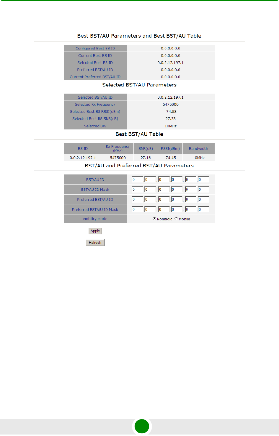
Chapter 4 - Operation BST/AU Parameters
BreezeMAX PRO 5000 CPE 62 Product Manual
The BST/AU page includes the following parameters:
Best BST/AU Parameters and Best BST/AU Table:
»Configured Best BS ID: the configured Preferred BST/AU ID. Together with
the BS ID Mask, it is used to define the range of BSs that can communicate
with the unit.
The BS ID comprises 6 octets of up to 3 digits each, where the range of
each group is 0 to 255.
The default BS ID is 0.0.0.0.0.0
Figure 4-10: BST/AU Page

Chapter 4 - Operation BST/AU Parameters
BreezeMAX PRO 5000 CPE 63 Product Manual
»Current Best BS ID
»Selected Best BS ID
»Preferred Best BS ID
»Current Preferred BS ID
Selected BST/AU Parameters:
»Selected BST/AU ID: The BST/AU ID to which the CPE is currently
connected.
»Selected Rx Frequency: The Rx Frequency of the BTS to which the CPE is
currently connected.
»Selected Best BS RSSI: The Rx RSSI of the BTS to which the CPE is
currently connected.
»Selected Best BS SNR (dB): The Rx SNR of the BTS to which the CPE is
currently connected.
»Selected BW: The bandwidth of the BTS to which the CPE is currently
connected.
Best BST/AU Table: displays the following details for each of the BS(s) found
during the scanning process:
»BS ID
»Rx Frequency (KHz)
»SNR (dB)
»RSSI (dBm)
»Bandwidth
BST/AU and Preferred BST/AU Parameters
»BST/AU ID
»BST/AU ID Mask
»Preferred BST/AU ID

Chapter 4 - Operation BST/AU Parameters
BreezeMAX PRO 5000 CPE 64 Product Manual
»Preferred BST/AU ID Mask
»Mobility Mode: enables defining the expected mobility of the SU: Nomadic
or Mobile.
The default is Nomadic.
After configuring the parameters, click Apply to save your changes.
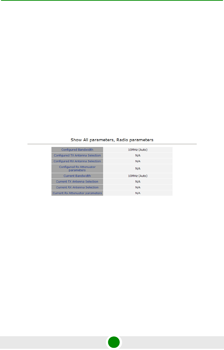
Chapter 4 - Operation Radio Parameters
BreezeMAX PRO 5000 CPE 65 Product Manual
4.8 Radio Parameters
The Radio Parameters page includes the following options:
Show
Frequency Scanning
Antenna Selection
4.8.1 Show
The Show page displays the Frequency and Bandwidth selected by the scanning
mechanism.
4.8.2 Frequency Scanning
The Frequency Scanning page enables viewing and updating the set of frequencies
to be used during the scanning process. The list of frequencies that participate in
the scanning process includes a set of frequencies belonging to the scanning
range and/or a set of up to 10 discrete frequencies.
The scanning range is defined by Start Rx Frequency, End Rx Frequency,
Scanning Main Step and Intermediate Steps. The set of frequencies to be scanned
is defined as follows:
The “Main Frequencies” are defined by the Start Frequency and Main Step, using
the formula F(N) =Start Frequency + N*Main Step;
Figure 4-11: Radio - Show Page

Chapter 4 - Operation Radio Parameters
BreezeMAX PRO 5000 CPE 66 Product Manual
F(1) = Start Frequency + Main Step, F(2) = Start Frequency +2*Main Step,...
End Frequency is the upper limit.
The Intermediate Steps can be used to define additional frequencies using a finer
resolution. The intermediate steps are defined as follows:
For example, If Steps B0, B1 and B4 are enabled and all other steps are disabled,
the scanned frequencies are: Start Frequency, Start Frequency + 125 KHz, Start
Frequency + 500 KHz, Start Frequency +N*Main Step, Start Frequency +N*Main
Step + 125 KHz, Start Frequency +N*Main Step + 500 KHz (N=1, 2,...). End
Frequency is the upper limit for the scanned frequencies.
In addition, the Discrete Frequencies option enables defining up to 10 discrete
frequencies to be used in the scanning process in addition to the frequencies
defined by the Frequency Scanning parameters.
NOTE
In the current version, intermediate steps are disabled.
Table 4-1: Intermediate Steps
Step Effect on scanned frequencies set when Step is Enabled
B0 Scan Start Frequency: Start Frequency is added to the set of “Main Frequencies”
B1 Intermediate Step=125 KHz: All intermediate frequencies defined by “Main Frequency” +
125 KHz are added to the scanning set
B2 Intermediate Step=250 KHz: All intermediate frequencies defined by “Main Frequency” +
250 KHz are added to the scanning set
B3 Intermediate Step=375 KHz: All intermediate frequencies defined by “Main Frequency” +
375 KHz are added to the scanning set
B4 Intermediate Step=500 KHz: All intermediate frequencies defined by “Main Frequency” +
500 KHz are added to the scanning set
B5 Intermediate Step=625 KHz: All intermediate frequencies defined by “Main Frequency” +
625 KHz are added to the scanning set
B6 Intermediate Step=750 KHz: All intermediate frequencies defined by “Main Frequency” +
750 KHz are added to the scanning set
B7 Intermediate Step=875/1250 KHz: All intermediate frequencies defined by “Main
Frequency” + 1250 KHz are added to the scanning set.
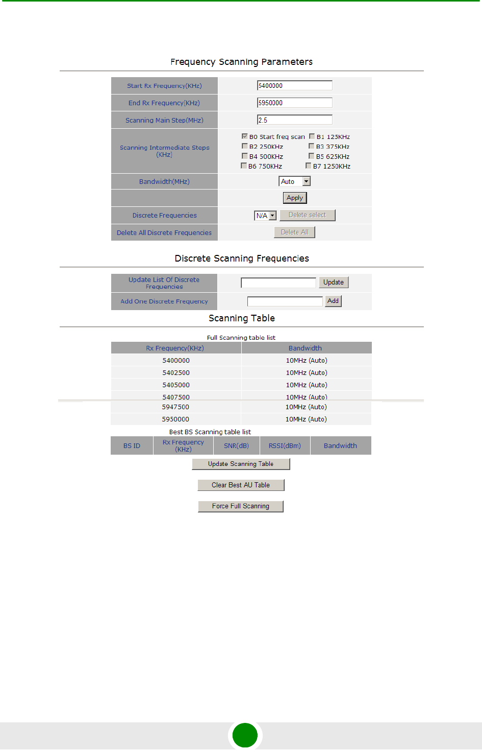
Chapter 4 - Operation Radio Parameters
BreezeMAX PRO 5000 CPE 67 Product Manual
The Frequency Scanning menu includes the following fields:
Scanning Table: displays the list of all current frequencies that participate in
the full scanning process. Following the Full Scanning Table, the Best BS
Scanning Table displays all the frequencies associated with BSs that are
included in the current Best BS Table.
Figure 4-12: Frequency Scanning Page

Chapter 4 - Operation Radio Parameters
BreezeMAX PRO 5000 CPE 68 Product Manual
Start Rx Frequency (KHz): the lowest frequency in the range of frequencies to
be scanned (in KHz).
The available values depend on the radio band of the unit.
End Rx Frequency (KHz): the highest frequency in the range of frequencies to
be scanned (in KHz).
The available values depend on the radio band of the unit.
Scanning Main Step (MHz): the Main Scanning Step that together with the
Intermediate Scanning Steps define the frequencies to be scanned between the
Start and End Rx Frequencies.
The main steps can be 2.5 MHz or 5 MHz. The default is 2.5 MHz.
Scanning Intermediate Steps (KHz): the Intermediate Scanning Steps that
together with the Main Scanning Step define the frequencies to be scanned
between the Start and End Rx Frequencies.
The Intermediate Scanning Steps include 8 Steps that define the intermediate
scanning steps as described above. The default is Enable for the B0 Start
Frequency Scan.
Bandwidth: enables to select either a specific bandwidth (according to the
options supported by the unit) or scan all supported bandwidths (Auto).
The default is Auto mode.
To change the bandwidth, select the required bandwidth from the list and click
Apply. A reset required message is displayed. Click OK to reset the unit, or
Cancel to cancel the operation.
Discrete Frequencies: enables editing the list of discrete frequencies that will
be included in the Frequency Scanning Table. If no discrete frequency has
been added, N/A will be displayed. To delete a discrete frequency from the list,
NOTE
In the current version, intermediate steps are disabled.
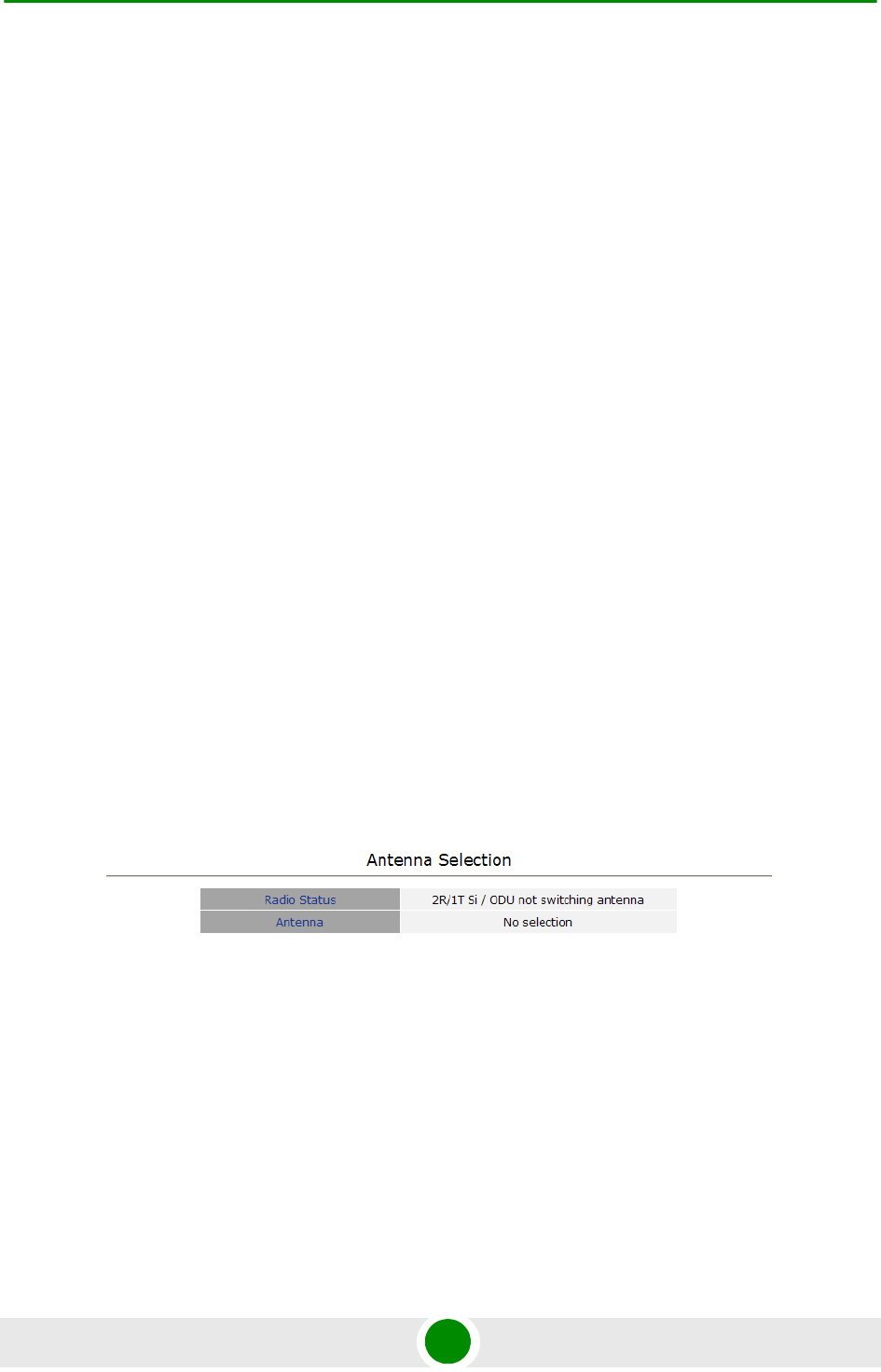
Chapter 4 - Operation Radio Parameters
BreezeMAX PRO 5000 CPE 69 Product Manual
first selecting the frequency to be deleted and click Delete select. The Delete
select button is available only if at least one discrete frequency is added.
Delete All Discrete Frequencies: to delete all discrete frequencies, click on
Delete All.
Discrete Scanning Frequencies: enables to enter discrete frequencies, as
follows:
»Update List of Discrete Frequencies: Enter a list of up to 10 discrete
frequencies in steps of 2.5MHz, separated by commas (no space). This list
will replace the current list of discrete frequencies.
»Add One Discrete Frequency: Enter one frequency to be added to the
current list of discrete frequencies.
Update Scanning Table: select this option to update the frequency scanning
table in run time (without resetting the unit).
Clear Best BS Table: select this option to clear the current Best BS Table.
Typically this should be done prior to initiating a full scanning process (see
below).
Force Full Scanning: select this option to initiate a full scanning process.
4.8.3 Antenna Selection
The Antenna Selection page enables viewing the parameters of the integrated
antenna. The following parameters are displayed:
Radio Status
Antenna: enables selection of antenna. Currently only one integrated antenna
is supported, and therefore selection is not available.
Figure 4-13: Antenna Selection Page
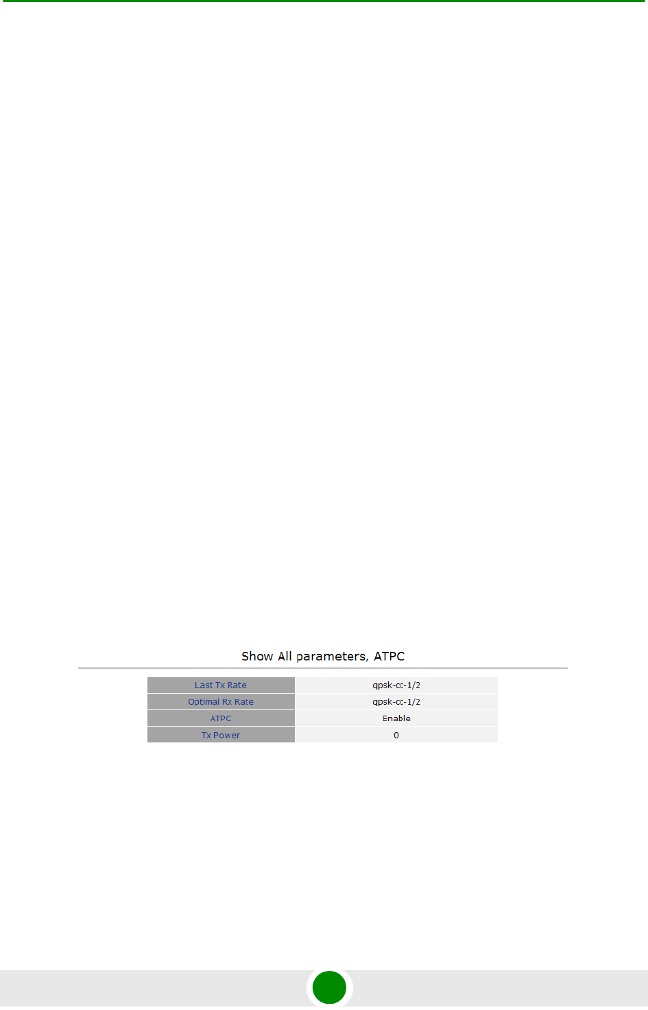
Chapter 4 - Operation ATPC Parameters
BreezeMAX PRO 5000 CPE 70 Product Manual
4.9 ATPC Parameters
In regular operation, the level of the signal transmitted by the SU is controlled by
the Adaptive Transmission Power Control (ATPC) mechanism of the serving BS.
The ATPC page enable temporary control of the signal transmitted by the SU. It is
intended for test purposes only.
These settings will not be saved and will automatically return to original values as
received from the BS when the unit resets or upon closing the web interface.
The ATPC menu includes the following sub-menus:
Show
ATPC
4.9.1 Show
Select this option to view the current Multirate and ATPC parameters:
Last Tx Rate: the last detected transmission rate
Optimal Rx Rate: the transmission rate best suited to the connection
ATPC: The current status (Enabled/Disabled) of the ATPC mechanism
Tx Power: the transmission power level
Figure 4-14: ATPC Show Page
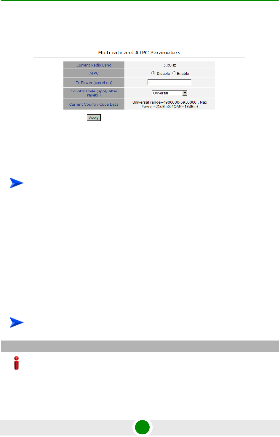
Chapter 4 - Operation ATPC Parameters
BreezeMAX PRO 5000 CPE 71 Product Manual
4.9.2 ATPC
From the ATPC page, you can enable/disable the ATPC mechanism and select
your country code.
1Select Disable to temporarily disable ATPC for testing purposes. You will be
prompted to enter the requested Tx Power. The available range depends on
unit type/radio band.
The default Tx Power is the last power level used before the ATPC algorithm
was disabled.
2Click Apply.
3Upon completing the test, enable ATPC to resume normal operation. If not
enabled manually, ATPC will be enabled automatically after the next reset or
when closing the web interface.
Figure 4-15: ATPC Page
To enable/disable the ATPC mechanism:
To select a country code:
IMPORTANT
The selected Country Code must comply with applicable local radio regulations.

Chapter 4 - Operation ATPC Parameters
BreezeMAX PRO 5000 CPE 72 Product Manual
Select the required country code from the list and reset the unit to apply the new
country code.
The Current Country Code field displays the country code that is currently used.
After performing reset to the unit, the configured country code becomes the
current country code.
The country code names may differ slightly from the names displayed in the BTS.
The following table lists the available country codes and their matching name in
the BTS.
Table 4-2: Country Codes
BTS Band Name PRO 5000 Country Code
4.9 GHz Universal
4.9 GHz Brazil FCC FCC/Brazil 4.9
4.9 GHz Japan Japan 4.9
5.1-5.3 GHz ETSI ETSI 5.1-5.3
5.3 GHz ETSI ETSI 5.3
5.2 GHz ETSI ETSI 5.1
5.2 GHz FCC FCC 5.1
5.3 GHz FCC FCC 5.3
5.1-5.3 GHz FCC FCC 5.1-5.3
5.1 GHz FAAA AA 5.1
5.4 GHz Universal 5.4 Universal
5.9 GHz Universal
5.4 GHz ETSI ETSI 5.4
5.8 GHz ETSI
5.4 GHz FCC FCC 5.4
5.8 GHz FCC FCC 5.8
5.4-5.8 GHz ETSI
5.4-5.8 GHz FCC FCC 5.4-5.8
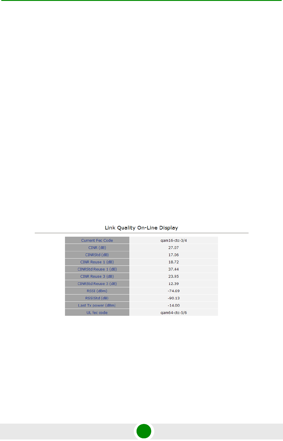
Chapter 4 - Operation Performance Monitor
BreezeMAX PRO 5000 CPE 73 Product Manual
4.10 Performance Monitor
The Performance Monitor Page enables viewing performance monitoring of link
quality, and Ethernet counters, and enables to set the monitoring intervals. The
CPE collects data on a regular basis and is able to deliver the data to the Access
Control Server NMS (Network Management Station) upon request.
The Performance Monitor menu includes the following options:
Link Quality Counters Page
Ethernet Counters
Integration Time
4.10.1 Link Quality Counters Page
The Link Quality On-Line Display table displays read-only information related to
the quality of the link between the CPE and the BTS. The display is updated every
2 seconds based on histograms/counters collected during this period.
The Link Quality Counters page displays the following counters:
Current Fec Code
CINR (dB): the average Carrier to Interference and Noise Ratio of the signal
Figure 4-16: Link Quality Counters Page
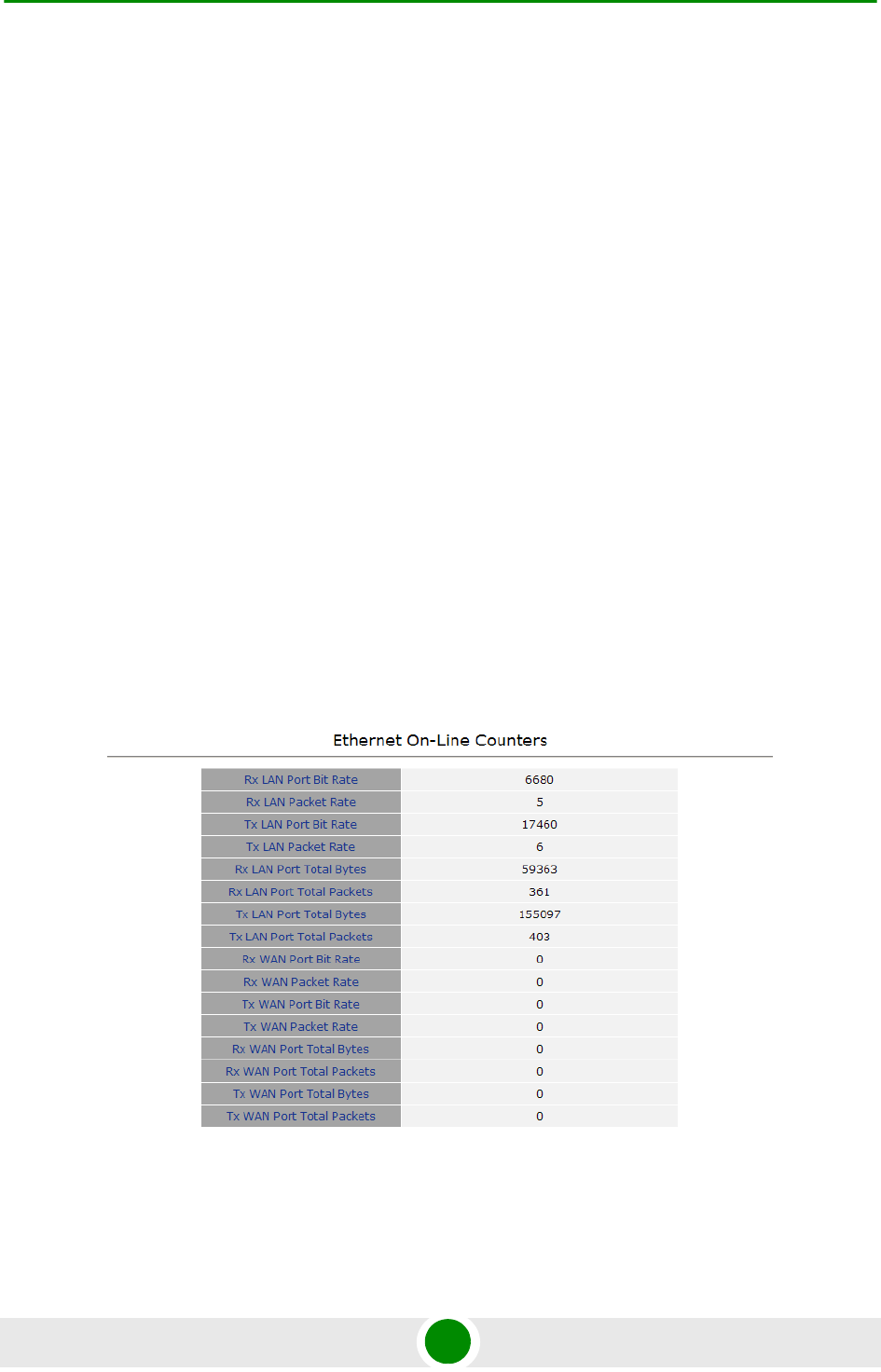
Chapter 4 - Operation Performance Monitor
BreezeMAX PRO 5000 CPE 74 Product Manual
CINRStd (dB)
CINR Reuse 1 (dB)
CINRStd Reuse 1 (dB)
CINR Reuse 3 (dB)
CINRStd Reuse 3 (dB)
RSSI
RSSIStd
Last Tx Power (dBm)
UL Fec Code
4.10.2 Ethernet Counters
The Ethernet On-Line Counters page displays RX and Tx levels for the Ethernet
connection.
Figure 4-17: Ethernet Counters Page
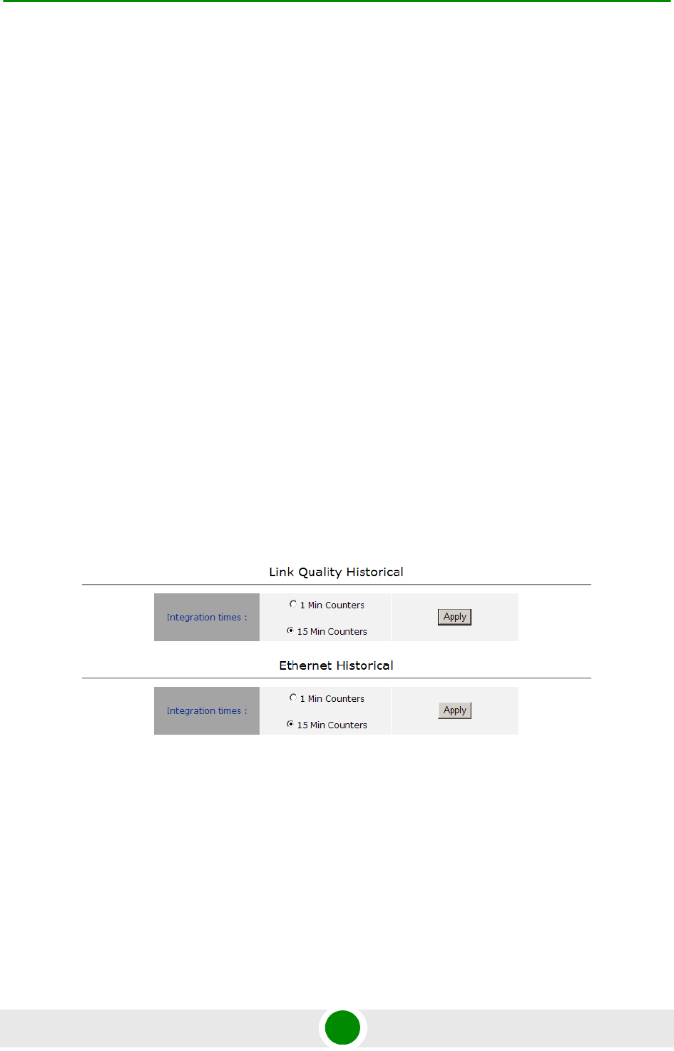
Chapter 4 - Operation Performance Monitor
BreezeMAX PRO 5000 CPE 75 Product Manual
The Ethernet On-Line Counters table displays a continuously updated list of the
traffic counters. The display is updated every 2 seconds based on counters
collected during this period. The displayed counters include the following for each
port (LAN/WAN) and each direction (TX/RX):
Bit Rate
Packet Rate
Total Bytes
Total Packets
Rate counts are the average rate (Bytes/Packets per second) for the last
measurement interval (2 seconds).
Total counts are the accumulated number of Bytes/Packets since the last unit
reset or the last Counters Reset.
4.10.3 Integration Time
The Integration Time page enables to set the frequency with which the CPE will
monitor traffic statistics on both the WiMAX link and Ethernet link.
The Link Quality Historical table enables to define a time period for monitoring the
WiMAX WAN port link to either 1 or 15 minutes.
The Ethernet Historical table enables to define a time period for monitoring the
Ethernet LAN port link to either 1 or 15 minutes.
Figure 4-18: Integration Time Page

Chapter 4 - Operation Performance Monitor
BreezeMAX PRO 5000 CPE 76 Product Manual
To set the time period, select the required option and click Apply.

Chapter 4 - Operation Service Parameters
BreezeMAX PRO 5000 CPE 77 Product Manual
4.11 Service Parameters
The Service Parameters page enables viewing the service related parameters
configured via the BTS.
The Service Parameters page displays the following:
Service Line Count: this is the number of configured services and corresponds
to the number of service rules in the Service Definition table.
Operation Mode: displays the convergence sublayer (CS) in the wireless access
network: IP CS (DSCP based classification) or Ethernet CS (VLAN based
classification).
Service Definition table: displays the Service Rules to be used for handling the
relevant classifiers (VLAN/DSCP) of packets processed by the units. For each
service rule, the following parameters are displayed:
»Service ID: up to 8 non-overlapping Service Rules can be defined via the
BTS.
»VLAN ID Configured: from 0 to 4095
»VLAN Priority Configured: from 0 to 7
»DSCP Configured: from 0 to 63
»DSCP Marking: Enabled/Disable:
When enabled, the DSCP value of a packet arriving from the Ethernet port
must be 0 (otherwise it will be discarded). Before forwarding to the wireless
port the 0 DSCP value will be replaced by the defined DSCP value and the
VLAN tag will be removed. For packets with this DSCP value arriving from
Figure 4-19: Service Page

Chapter 4 - Operation Service Parameters
BreezeMAX PRO 5000 CPE 78 Product Manual
the wireless port, the defined VLAN tag will be added before forwarding it to
the Ethernet port (without changing the DSCP value).
If DSCP Marking is disabled, a packet with the defined VLAN tag (VLAN ID
and Priority) will be forwarded to the wireless port after removal of the
VLAN tag. The DSCP value of these packets is the DSCP configured (the
packet will be forwarded regardless of its DSCP value). For packets with the
configured DSCP value arriving from the wireless port, the defined VLAN
tag (VLAN ID and Priority) will be added before forwarding to the Ethernet
port.
For additional information on service configuration, refer to the System Manual.
NOTE
In the current version, the Service Definition table is empty.
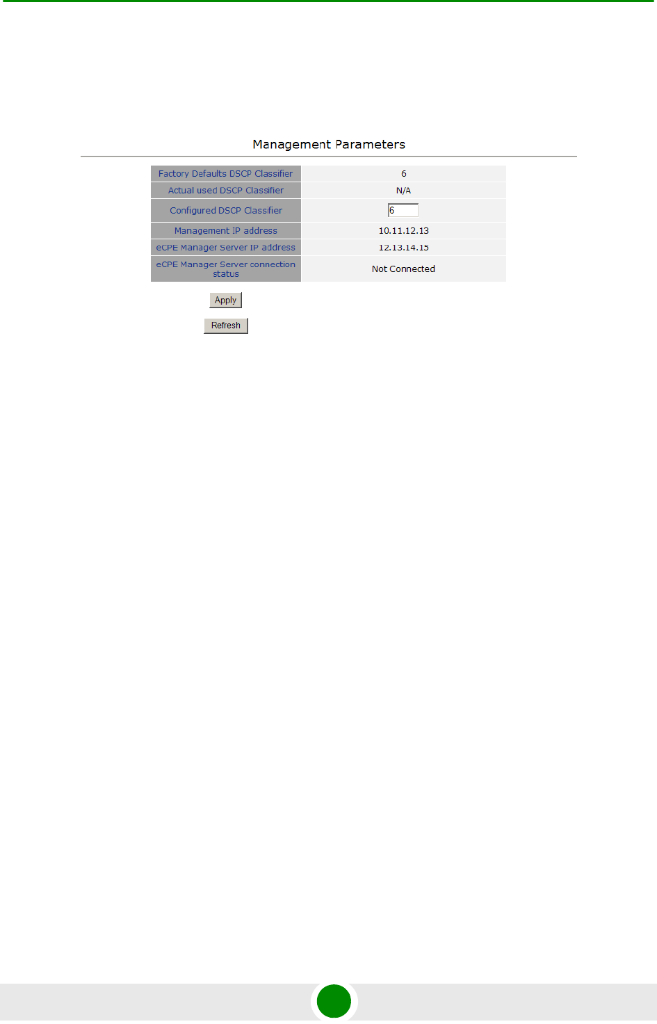
Chapter 4 - Operation Management Parameters
BreezeMAX PRO 5000 CPE 79 Product Manual
4.12 Management Parameters
The Management page enables viewing the parameters related to remote (over the
air) management of the device and to set the DSCP classifier.
The following parameters are displayed:
Factory Defaults DSCP Classifier
Actual Used DSCP Classifier: the DSCP classifier used when the CPE is
connected. When the CPE is not connected, the value is N/A.
Configured DSCP (to change, enter a value and click Apply). Range 0-63;
Default 6
Management IP Address (acquired from a DHCP server during Network Entry)
eCPE Manager IP Address (acquired from a DHCP server, or Not Available)
eCPE Manager Connection Status (Up, Down or Not Connected)
Figure 4-20: Management Page

Chapter 4 - Operation Logout
BreezeMAX PRO 5000 CPE 80 Product Manual
4.13 Logout
To log out, click on the Logout menu. The following window is displayed:
Click on the Logout button. The Login page is displayed.
Figure 4-21: Logout Page

Chapter 4 - Operation Parameters Summary
BreezeMAX PRO 5000 CPE 81 Product Manual
4.14 Parameters Summary
Table 4-3: SU Parameters Summary
Parameter Range Default Run-Time
Updated
Unit Control Parameters
Password Up to 20 printable characters,
case sensitive
installer No
Local TFTP Server IP Address IP address 192.168.254.250 Yes
Configuration Upload File
Name
Configuration Download File
Name
Choose Upload/Download
Action
Upload
Download
Upload No
TM & PM Files
SW File Name Yes
Ethernet Port Auto Negotiation
Enable/Disable
Disable
Enable
Enable No
Ethernet Port Speed and
Duplex
10Mbps Half-Duplex
10Mbps Full-Duplex
100Mbps Half-Duplex
100Mbps Full-Duplex
No
Registration Parameters
User Name 1 to 32 printable characters,
case sensitive
<MAC_Address>@WiMa
x.com
No
Password 1 to 32 printable characters,
case sensitive
No
Organization Up to 32 printable characters No
Address Up to 32 printable characters Yes
Country Up to 12 printable characters Yes

Chapter 4 - Operation Parameters Summary
BreezeMAX PRO 5000 CPE 82 Product Manual
Authentication Not Authenticated
EAP TTLS
EAP TLS
EAP TTLS Yes
BS ID Parameters
BST/AU ID 6 octets of up to 3 digits each.
Each group range is 0-255.
0.0.0.0.0.0 Yes
BST/AU ID Mask 6 octets of up to 3 digits each.
Each group range is 0-255.
0.0.0.0.0.0 Yes
Preferred BST/AU ID 6 octets of up to 3 digits each.
Each group range is 0-255.
0.0.0.0.0.0 Yes
Preferred BS ID Mask 6 octets of up to 3 digits each.
Each group range is 0-255.
0.0.0.0.0.0 Yes
Mobility Mode Nomadic
Mobile
Nomadic Yes
Radio Parameters
Start Rx Frequency (KHz) 5400000 to 5950000
Resolution for all bands is
0.125 MHz
5400000 Yes
(after Update
Scanning Table)
End Rx Frequency (KHz) 5400000 to 5950000
Resolution for all bands is
0.125 MHz
5950000 Yes
(after Update
Scanning Table)
Scanning Main Step (MHz) 2.5 MHz
5 MHz
2.5 MHz Yes
(after Update
Scanning Table)
Set Bandwidth to Scan 5 MHz
10 MHz
Auto
Auto Yes
Multirate and ATPC Parameters
ATPC Enable
Disable
Enable Yes
Table 4-3: SU Parameters Summary
Parameter Range Default Run-Time
Updated

Chapter 4 - Operation Parameters Summary
BreezeMAX PRO 5000 CPE 83 Product Manual
Set Tx Power 21 to -26 Last power used by
ATPC
Yes
Management
Configured DSCP Classifier 0-63 6 No
Table 4-3: SU Parameters Summary
Parameter Range Default Run-Time
Updated

A
Appendix
Troubleshooting


Appendix A - Troubleshooting PRO CPE Troubleshooting
BreezeMAX PRO 5000 CPE 86 Product Manual
A.1 PRO CPE Troubleshooting
Refer to the BreezeMAX Troubleshooting Guide for additional information on
troubleshooting,
Problem and Indication Possible Cause Corrective Action
Power Failure: None of the
IDU LEDs illuminate after
connecting to power
Mains power problem Verify mains power availability on the power outlet to
which the power supply is connected. Try using a
different outlet.
Mains power connection
problem
Verify that the AC jack of the power cord is
connected properly to the unit.
Verify that the AC plug of the power cable is
connected properly to the mains power outlet.
Unit failure Replace the IDU.
IDU-ODU connection
problem: None of the SAU’s
indicators illuminate
IDU-ODU connection
problem
Verify that the IDU-ODU cable is connected
properly.
Unit failur Try replacing the IDU. If the problem persists, try
replacing the IDU-ODU cable. If the problem
persists, try replacing the ODU.
When connected to the
data equipment, the
Ethernet Integrity Indicator
(green LED) is off, and/or
the Ethernet Activity
Indicator (yellow LED) does
not blink when there should
be traffic on the Ethernet
port.
Wrong type of Ethernet
cable or faulty cable.
If connected directly to PC-use a straight cable.
Otherwise-use a crossed cable. If the problem
persists, try replacing the cable.
If a hub or switch is installed between the PC and
the CPE, verify first the Ethernet connection integrity
between the hub/switch and the PC by checking the
Ethernet LEDs at the hub/switch and at the PC's
NIC card. If not ok, try replacing the cable.
IDU-ODU cable problem. Verify that the IDU-ODU cable is in order and
connected properly. Using SAU, verify that PWR
LED is on and ALRM LED is off.
Unit failur Try replacing the IDU. If the problem persists, try
replacing the IDU-ODU cable. If the problem
persists, try replacing the ODU.

Appendix A - Troubleshooting PRO CPE Troubleshooting
BreezeMAX PRO 5000 CPE 87 Product Manual
The Ethernet Activity and/or
Integrity LEDs are on, but
no management access
using Telnet or web
browser, and the unit does
not respond to ping.
Wrong IP configuration Make sure that the PC is on the same subnet as the
unit. The unit's IP address for management
purposes is 192.168.254.251, and the subnet mask
is 255.255.255.0.
Wrong Ethernet port
operation mode
Make sure that the speed and duplex settings in the
PC match the configuration in the unit. The default
operation mode is Auto Negotiation, and supported
speeds are 10/100 Mbps, Full or Half Duplex.
ARP table in the PC
contains a wrong MAC
address for the
192.168.254.251 IP
address (due to a recent
connection to another SU).
Perform arpV-d at the DOS command prompt to
clear the ARP table, and retry the Telnet command
to the unit.
Bridging table in SU is full
(expected when Number of
Supported Devices,
configurable from the Base
station's side, is set to a
small number.
Reset the SU to clear the table and retry the Telnet
command to the unit.
Scanning failed and/or
Base Station not found:
None of the LINK QUALITY
LEDs illuminate.
Configuration problem Verify proper configuration of Frequency Scanning
parameters.
Verify proper configuration of BS ID parameters.
If proper configuration parameters are not known,
press the RESET button for more than 5 seconds to
activate the factory default configuration
Poor link quality Try changing the location of the unit/antenna to
improve link quality using the LINK QUALITY LEDs.
Signal is too strong:All LINK
QUALITY LEDs, including
the red LED are on
Signal is too strong-may
cause saturation.
Change the location/direction of the unit/antenna to
reduce signal strength using the LINK QUALITY
LEDs.
Authentication Failure: LED
1 (ELNK-orange) of the
LINK QUALITY bar blinks.
Authentication problem: Enter User Name and User Password and reset the
unit. If the problem persists, contact the operator.
Problem and Indication Possible Cause Corrective Action

Glossary

Glossary
BreezeMAX PRO 5000 CPE 89 Product Manual
AAA Authentication, Authorization, and Accounting (pronounced "triple a."). A system (or
several systems) that controls what resources users have access to, and keeps track of
the activity of users over the network.
ACS Auto Configuration Server. A CPE management system supporting secure
auto-configuration as well as other CPE management functions.
AES-CCM Advanced Encryption Standard - Counter mode with Cipher-block chaining Message
authentication code.
Counter mode with Cipher-block chaining Message authentication code (CCM) is an
encryption protocol in the 802.11i standard. The CCM protocol (CCMP) is based upon
the CCM mode of the AES encryption algorithm and utilizes 128-bit keys.
APD Automatic Platform Detection. A mechanism that dtects the wireless link protocol used
by the Base Station, enabling automatic selection of the operation mode to be used
Subscriber Unit.
ARP Address Resolution Protocol. Internet protocol used to map an IP address to a MAC
address. Defined in RFC 826
ATPC Automatic Transmit Power Control
AWGN Additive white Gaussian noise, also known as white noise, contains equal energy per
frequency across the spectrum of the noise employed.
BPSK Binary Phase-Shift Keying. A data transfer technique. BPSK transmits data using two
phase modulation signals, one phase representing a binary one, and the other
representing a binary zero. The signal is divided into bits; their status is determined by
the preceding wave. If the wave changes, for example, the signal is reversed.
BS Base Station. The WiMAX BS is an entity that implements the WiMAX MAC and PHY in
compliance with the IEEE 802.16e standard. A BS operates on one frequency
assignment, and incorporates scheduler functions for uplink and downlink resources.
BTS Base Transceiver Station. A wireless network element that provides the radio interface
of the network. The BTS comprises the radio transmission and reception devices, and
also manages the signal processing related to the air interface.
BWA Broadband Wireless Access
CF Compact Flash. A popular memory card that uses flash memory to store data on a very
small card.
CINR Carrier-to-Interference plus Noise Ratio (expressed in dB)
CLI Command Line Interface. A user interface where the user sees the command line on
the monitor and a prompt that is waiting to accept instructions from the user. The user
types in the command, the computer acts on that command and then issues a new
prompt for the next instruction from the user.
CPE Customer Premise Equipment. Communications equipment that resides on the
customer's premises.
CPU Central Processing Unit

Glossary
BreezeMAX PRO 5000 CPE 90 Product Manual
CRC Cyclical Redundancy Check. A common technique for detecting data transmission
errors, in which the frame recipient calculates a remainder by dividing frame contents
by a prime binary divisor and compares the calculated remainder to a value stored in
the frame by the sending equipment.
CS Convergence Sublayer. Particular protocols that are responsible for gathering and
formatting higher layer information so it can be processed by the lower layers.
CSMA/CD Carrier Sense Multiple Access with Collision Detection. Media-access mechanisms
wherein devices ready to transmit data first check the channel for a carrier. If no carrier
is sensed for a specific period of time, a device can transmit. If two devices transmit at
once, a collision occurs and is detected by all colliding devices. This collision
subsequently delays retransmissions from those devices for some random length of
time. Ethernet and IEEE 802.3 use CSMA/CD access.
CW Continuous Wave. An unmodulated RF signal.
CWMP CPE WAN Management Protocol. See also TR-069.
DHCP Dynamic Host Configuration Protocol. A protocol for dynamically assigning IP
addresses from a pre-defined list to nodes on a network. Using DHCP to manage IP
addresses simplifies client configuration and efficiently utilizes IP addresses.
DL Down Link
DSCP Differentiated Service Code Point, AKA DiffServ: An alternate use for the ToS byte in IP
packets. Six bits of this byte are being reallocated for use as the DSCP field where
each DSCP specifies a particular per-hop behavior that is applied to the packet.
EAP Extensible Authentication Protocol, A protocol used between a user station and an
authenticator or authentication server. It acts as a transport for authentication methods
or types. It, in turn may be encapsulated in other protocols, such as 802.1x and
RADIUS. EAP is defined by RFC 2284.
EAP-TTLS Extensible Authentication Protocol-Tunneled Transport Layer Service. A type of mutual
authentication protocol where just the server sends a digital certificate to identify itself
to the clients.
EMC Electro-Magnetic Compatibility. The capability of equipment or systems to be used in
their intended environment within designed efficiency levels without causing or
receiving degradation due to unintentional EMI (Electro Magnetic Interference). EMC
generally encompasses all of the electromagnetic disciplines.
ETSI European Telecommunications Standards Institute. A non-profit organization producing
voluntary telecommunications standards used throughout Europe, some of which have
been adopted by the EC as the technical base for Directives or Regulations.
FCC Federal Communications Commission. A U.S. government agency that supervises,
licenses, and controls electronic and electromagnetic transmission standards.
FEC Forward Error Correction. A method of communicating data that can correct errors in
transmission on the receiving end. Prior to transmission, the data is put through a
predetermined algorithm that adds extra bits specifically for error correction to any
character or code block. If the transmission is received in error, the correction bits are
used to check and repair the data.

Glossary
BreezeMAX PRO 5000 CPE 91 Product Manual
FFT Fast Fourier Transform. An algorithm for converting data from the time domain to the
frequency domain; often used in signal processing.
FIPS Federal Information Processing Standards. The Federal Information Processing
Standard (FIPS) Publication 140-2 1, called Security Requirements for Cryptographic
Modules, is a United States security standard used to certify cryptographic modules.
FTP File Transfer Protocol. A protocol for exchanging files over the Internet. FTP uses the
Internet's TCP/IP protocols to enable data transfer.
GUI Graphical User Interface. In a GUI operating system, the user responds to graphic
images on the screen instead of typing in commands in response to a prompt.
HTTP HyperText Transfer Protocol. The protocol used to transmit and receive data over the
World Wide Web.
IDU Indoor Unit
IEEE Institute of Electrical and Electronics Engineers. IEEE (pronounced I-triple-E) is an
organization composed of engineers, scientists, and students. The IEEE is best known
for developing standards for the computer and electronics industry. In particular, the
IEEE 802 standards for local-area networks are widely followed.
IEEE 802.3 A Local Area Network protocol suite commonly known as Ethernet. Ethernet uses
Carrier Sense Multiple Access bus with Collision Detection CSMA/CD. This method
allows users to share the network cable. However, only one station can use the cable at
a time. A variety of physical medium dependent protocols are supported.
IEEE 802.16 Also known as WIMAX. A group of broadband wireless communications standards for
metropolitan area networks (MANs) developed by a working group of the IEEE.
IEEE 802.16e 802.16e, also known as 802.16-2005, is an IEEE standard addressing mobility of
wireless broadband (WiMax). IEEE 802.16e is sometimes called Mobile WiMAX, after
the WiMAX forum for interoperability. 802.16e, based on an existing WiMAX standard
802.16a, adds WiMAX mobility in the 2-to-6 GHz-licensed bands. 802.16e allows for
fixed wireless and mobile Non Line of Sight (NLOS) applications primarily by enhancing
the OFDMA (Orthogonal Frequency Division Multiple Access).
IP Internet Protocol. The standard that defines how data is transmitted over the Internet.
IP bundles data, including e-mail, faxes, voice calls and messages, and other types,
into "packets", in order to transmit it over public and private networks.
LAN Local Area Network. A computer network limited to a small geographical area, such as
a single building. The network typically links PCs as well as shared resources such as
printers.
LED Light Emitting Diode.
MAC Address Standardized data link layer address that is required for every port or device that
connects to a LAN. Other devices in the network use these addresses to locate specific
ports in the network and to create and update routing tables and data structures. MAC
addresses are 6bytes long and are controlled by the IEEE.

Glossary
BreezeMAX PRO 5000 CPE 92 Product Manual
MCS Multipoint Communications Systems. Applications licensed at 2500 MHz in Canada. A
wide variety of applications are possible including one-way and two-way transmission
and a diversity of distribution capacities.
MMDS Multichannel Multipoint Distribution Service. MMDS is a licensed wireless service that
has the capability to provide broadband access. MMDS operates in several parts of the
2 GHz spectrum.
MSCHAP Microsoft Challenge Handshake Authentication Protocol. an implementation of the
CHAP protocol that Microsoft created to authenticate remote Windows workstations. In
most respects, MS-CHAP is identical to CHAP, but there are a few differences.
MS-CHAP is based on the encryption and hashing algorithms used by Windows
networks, and the MS-CHAP response to a challenge is in a format optimized for
compatibility with Windows operating systems.
MSS Maximum Segment Size.
NA Not Available or Not Applicable
NE Network Entry
NIC Network Interface Card. An expansion board you insert into a computer (or a built-in
component) that enables the computer to connect to a network. Most NICs are
designed for a particular type of network, protocol, and media, although some can
serve multiple networks.
ODU Outdoor Unit
OFDM Orthogonal Frequency Division Multiplexing: A method for multiplexing signals, which
divides the available bandwidth into a series of frequencies known as tones.
Orthogonal tones do not interfere with each other when the peak of one tone
corresponds with the null. The rapid switching, frequency-hopping technique is
intended to allow more robust data service.
OFDMA Orthogonal Frequency Division Multiple Access. It’s a logical extension of OFDM and a
modulation/multiple access technique. OFDMA divides a signal into sub-channels (i.e.
groups of carriers), with each sub-channel (or several sub-channels) being allocated to
a different subscriber.
PER Packet Error Rate. In a digital transmission, PER is the percentage of packets with
errors divided by the total number of packets that have been transmitted, received or
processed over a given time period.
PHY PHYsical Layer. The physical, or lowest, layer of the OSI Network Model. In a wireless
network, the PHY defines parameters such as data rates, modulation method, signaling
parameters, transmitter/receiver synchronization, etc. Within an actual radio
implementation, the PHY corresponds to the radio front end and baseband signal
processing sections.

Glossary
BreezeMAX PRO 5000 CPE 93 Product Manual
PPPoE Point-to-Point Protocol over Ethernet. PPPoE relies on two widely accepted standards:
PPP and Ethernet. PPPoE is a specification for connecting the users on an Ethernet to
the Internet through a common broadband medium, such as a single DSL line, wireless
device or cable modem. All the users over the Ethernet share a common connection,
so the Ethernet principles supporting multiple users in a LAN combines with the
principles of PPP, which apply to serial connections.
QAM Quadrature Amplitude Modulation. A technique used in wireless applications to double
the available bandwidth by combining two amplitude-modulated signals. The two
combined signals differ in phase by 90 degrees; this technique doubles the bandwidth
by combining the two signals at the source before transmission, transmitting digital data
at a rate of 4 bits per signal change.
QPSK Quadrature Phase Shift Keying. A data transfer technique used in coaxial cable
networks that sends data using modulating signals. Four different phases represent
data, with each signal's information determined by the signal before it. For example, if a
phase stays the same from one signal to the other, the information has not changed.
RADIUS Remote Authentication Dial-In User Service, an authentication and accounting system
used by many Internet Service Providers (ISPs). When you connect to the system you
must enter your username and password. This information is passed to a RADIUS
server, which checks that the information is correct, and then authorizes access to the
system.
RF Radio frequency. An AC signal of high enough frequency to be used for wireless
communications.
RSSI Received Signal Strength Indicator. A signal or circuit that indicates the strength of the
incoming (received) signal in a receiver.
R&TTE Radio & Telecommunications Terminal Equipment. The R&TTE Directive 1999/5/EC
governs the marketing and use of R&TTE equipment. With the exception of a few
categories of equipment, the Directive covers all equipment, which uses the radio
frequency spectrum. It also covers all terminal equipment attached to public
telecommunication networks.
Rx Receive
SAU SU Alignment Unit
SDARS Satellite Digital Audio Radio Service. A satellite-based direct-broadcast radio service in
which digitally encoded audio entertainment material is broadcast to earth-based
receivers from an orbiting satellite, either directly or via a repeater station.
SIP Session Initiation Protocol. An application-layer control IETF protocol that can
establish, modify, and terminate multimedia sessions such as Internet telephony calls
(VoIP). SIP can also invite participants to already existing sessions, such as multicast
conferences. Media can be added to (and removed from) an existing session. SIP
transparently supports name mapping and redirection services, which supports
personal mobility - users can maintain a single externally visible identifier regardless of
their network location.

Glossary
BreezeMAX PRO 5000 CPE 94 Product Manual
SNMP Simple Network Management Protocol. A network management protocol that provides
a means to monitor and control network devices, and to manage configurations,
statistics collection, performance, and security. SNMP works by sending messages,
called protocol data units (PDUs), to different parts of a network. SNMP-compliant
devices, called agents, store data about themselves in Management Information Bases
(MIBs) and return this data to the SNMP requesters.
SNR Signal to Noise Ratio. The ratio of the amplitude of a desired analog or digital data
signal to the amplitude of noise in a transmission channel at a specific point in time.
SNR is typically expressed logarithmically in decibels (dB). SNR measures the quality
of a transmission channel or a signal over a network channel. The greater the ratio, the
easier it is to identify and subsequently isolate and eliminate the effects of noise. SNR
also is abbreviated as S/N.
SU Subscriber Unit
TCP Transmission Control Protocol. Connection-oriented transport layer protocol that
provides reliable full-duplex data transmission. TCP is the part of the TCP/IP suite of
protocols that is responsible for forming data connections between nodes that are
reliable, as opposed to IP, which is connectionless and unreliable.
TCP/IP Transmission Control Protocol/Internet Protocol. A set of protocols developed by the
U.S. Department of Defense to allow communication between dissimilar networks and
systems over long distances. TCP/IP is the de facto standard for data transmission
over networks, including the Internet.
TDD Time Division Duplex is a duplexing technique dividing a radio channel in time to allow
downlink operation during part of the frame period and uplink operation in the
remainder of the frame period.
TFTP Trivial File Transfer Protocol. Simplified version of FTP that allows files to be
transferred from one computer to another over a network, usually without the use of
client authentication.
TR-069 TR-069 CPE WAN Management Protocol (CWMP) was created by the DSL Forum to
standardize management of CPEs over the Wide Area Network (WAN) . The TR-069
protocol specifically defines a common method for CPE devices to communicate with
an Auto Configuration Server (ACS).
Tx Transmit
UDP User Datagram Protocol. Connectionless transport layer protocol in the TCP/IP
protocol stack. UDP is a simple protocol that exchanges datagrams without
acknowledgments or guaranteed delivery, requiring that error processing and
retransmission be handled by other protocols. UDP is defined in RFC 768.
UL Up Link
VLAN Virtual Local Area Network. A group of devices on one or more LANs that are
configured with the same VLAN ID so that they can communicate as if they were
attached to the same wire, when in fact they are located on a number of different LAN
segments. Used also to create separation between different user groups.

Glossary
BreezeMAX PRO 5000 CPE 95 Product Manual
VoIP Voice over Internet Protocol. Provides an advanced digital communications network
that bypasses the traditional public switched telephone system and uses the Internet to
transmit voice communication. VoIP enables people to use the Internet as the
transmission medium for telephone calls by sending voice data in packets using IP
rather than by traditional circuit switched transmissions of the PSTN.
WAN Wide Area Network. A computer network that spans a relatively large geographical
area. Wide area networks can be made up of interconnected smaller networks spread
throughout a building, a state, or the entire globe.
WCS Wireless Communications Services. The variety of services available using frequencies
in the 2.3 GHz band for general fixed wireless use.
WEEE Waste Electronic and Electrical Equipment. The purpose of Directive 2002/96/EC on
waste electrical and electronic equipment (WEEE) is, as a first priority, the prevention of
waste electrical and electronic equipment (WEEE), and in addition, the reuse, recycling
and other forms of recovery of such wastes so as to reduce the disposal of waste. It
also seeks to improve the environmental performance of all operators involved in the
life cycle of electrical and electronic equipment, e.g. producers, distributors and
consumers and in particular those operators directly involved in the treatment of waste
electrical and electronic equipment.
WL (or W/L) Wireless LAN
WIMAX The name commonly given to the IEEE 802.16 standard. Specifications for fixed
broadband wireless metropolitan access networks (MANs) that use a
point-to-multipoint architecture. WIMAX supports very high bit rates in both uploading to
and downloading from a base station up to a distance of 30 miles.