Alvarion Technologies IF-24-SYNC Broadband Wireless Access System User Manual Flexible Hopping Definition Mode
Alvarion Ltd. Broadband Wireless Access System Flexible Hopping Definition Mode
UserManual.wiki
>
Alvarion Technologies
>
IF-24-SYNC User Manual
>
Appendix
Contents
1.
Users Manual
2.
Appendix
Appendix
Navigation menu
Upload a User Manual
Namespaces
Wiki Guide
HTML
PDF
Info
Views
User Manual
Discussion / Help
Navigation

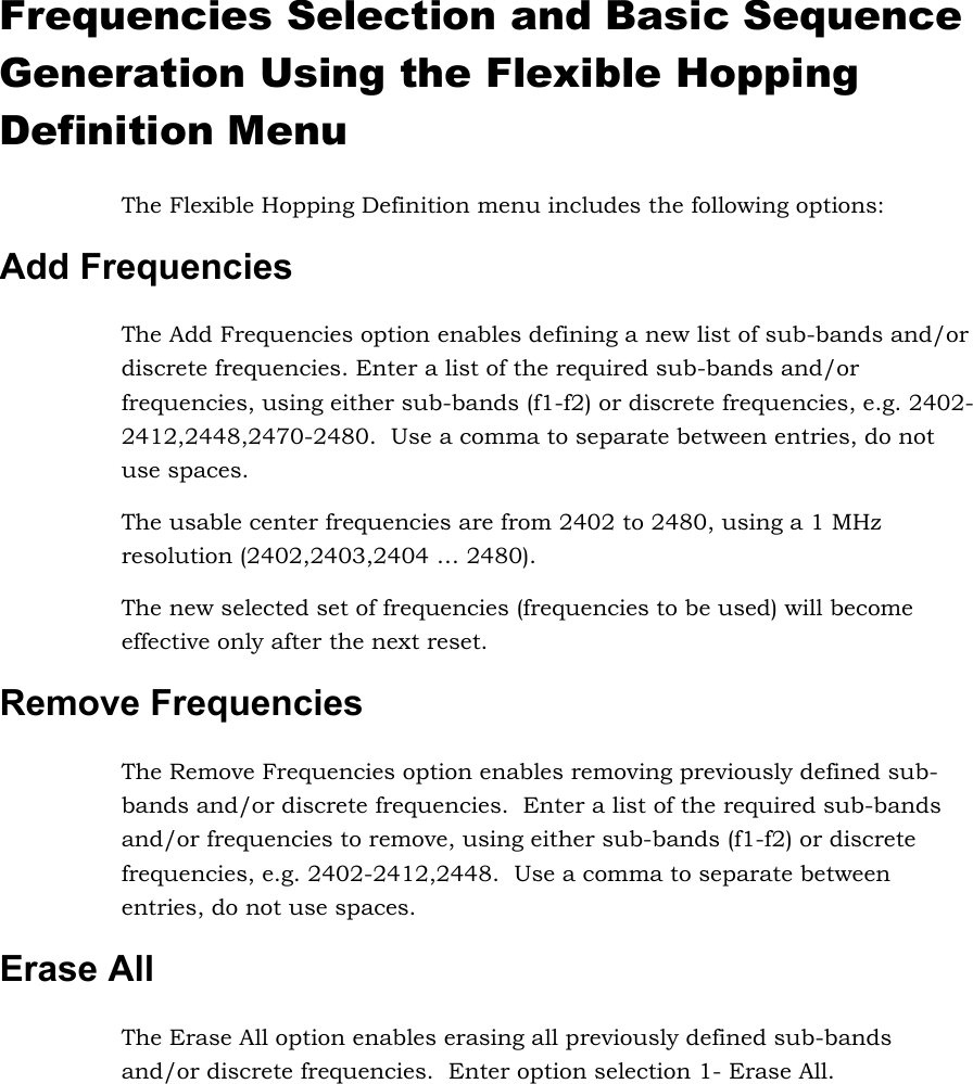
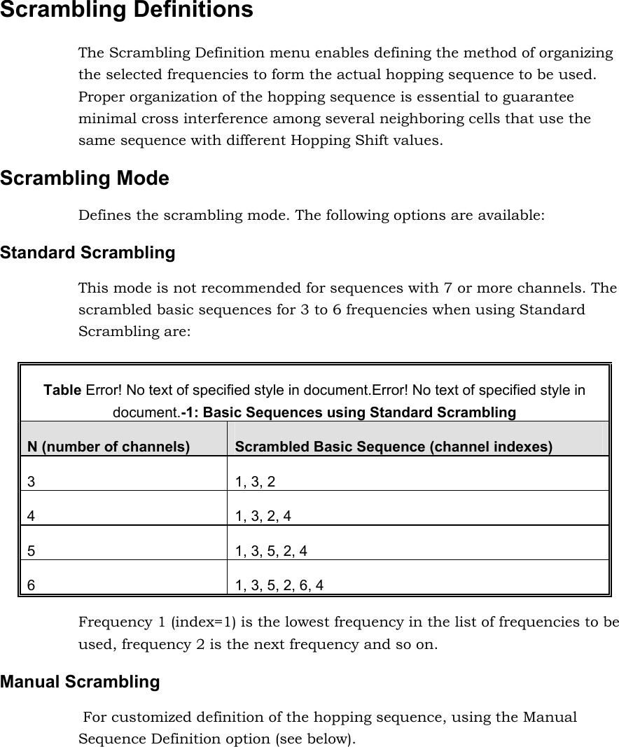
![Enhanced Scrambling Automatically generates hopping sequences using an enhanced algorithm. It is recommended that Enhanced Scrambling rather then Standard Scrambling be used. If the Enhanced Scrambling Mode is selected, the Spanning Factor parameter (see below) must be configured in the AU. The Enhanced Mode is not suitable for sequences with 6 or less frequencies. If Enhanced Scrambling is selected with sequences that have 6 or less frequencies, than Standard Scrambling is used by default. The scrambled sequence is generated according to the following rules: 1. The first channel in the basic scrambled sequence is frequency 1 (Frequency 1 (index=1) is the lowest frequency in the list of frequencies to be used, frequency 2 is the next frequency and so on.) 2. The index of each of the other channels is calculated by adding the Spanning Factor to the index of the previous channel. Note that the sequence is cyclic, meaning that adding 1 to the highest index in the sequence (Index=N where N is the number of channels in the sequence) will result in the first channel (Index=1). The scrambled basic sequence can also be calculated using the formula: Px (j)= {[(j-1)*X]mod(N)}+1 Where: X is the Spanning Factor N is the number of channels in the sequence (modulus) J is the sequence index Example: N=8, X=3 P1(5)={[(1-1)*3}mod8}+1=1 P2(5)={[(2-1)*3}mod8}+1=6 P3(5)={[(3-1)*3}mod8}+1=3 P4(5)={[(4-1)*3}mod8}+1=8 P5(5)={[(5-1)*3}mod8}+1=5 P6(5)={[(6-1)*3}mod8}+1=2 P7(5)={[(7-1)*3}mod8}+1=7 P8(5)={[(8-1)*3}mod8}+1=4 And the basic scrambled sequence is: 1, 4, 7, 2, 5, 8, 3, 6.](https://usermanual.wiki/Alvarion-Technologies/IF-24-SYNC.Appendix/User-Guide-387484-Page-5.png)