Alvarion Technologies IF-57 IP Broadband Wireless Access System User Manual SystemManual
Alvarion Ltd. IP Broadband Wireless Access System SystemManual
UserManual.wiki
>
Alvarion Technologies
>
IF 57 User Manual
User Manual
Navigation menu
Upload a User Manual
Namespaces
Wiki Guide
HTML
PDF
Info
Views
User Manual
Discussion / Help
Navigation


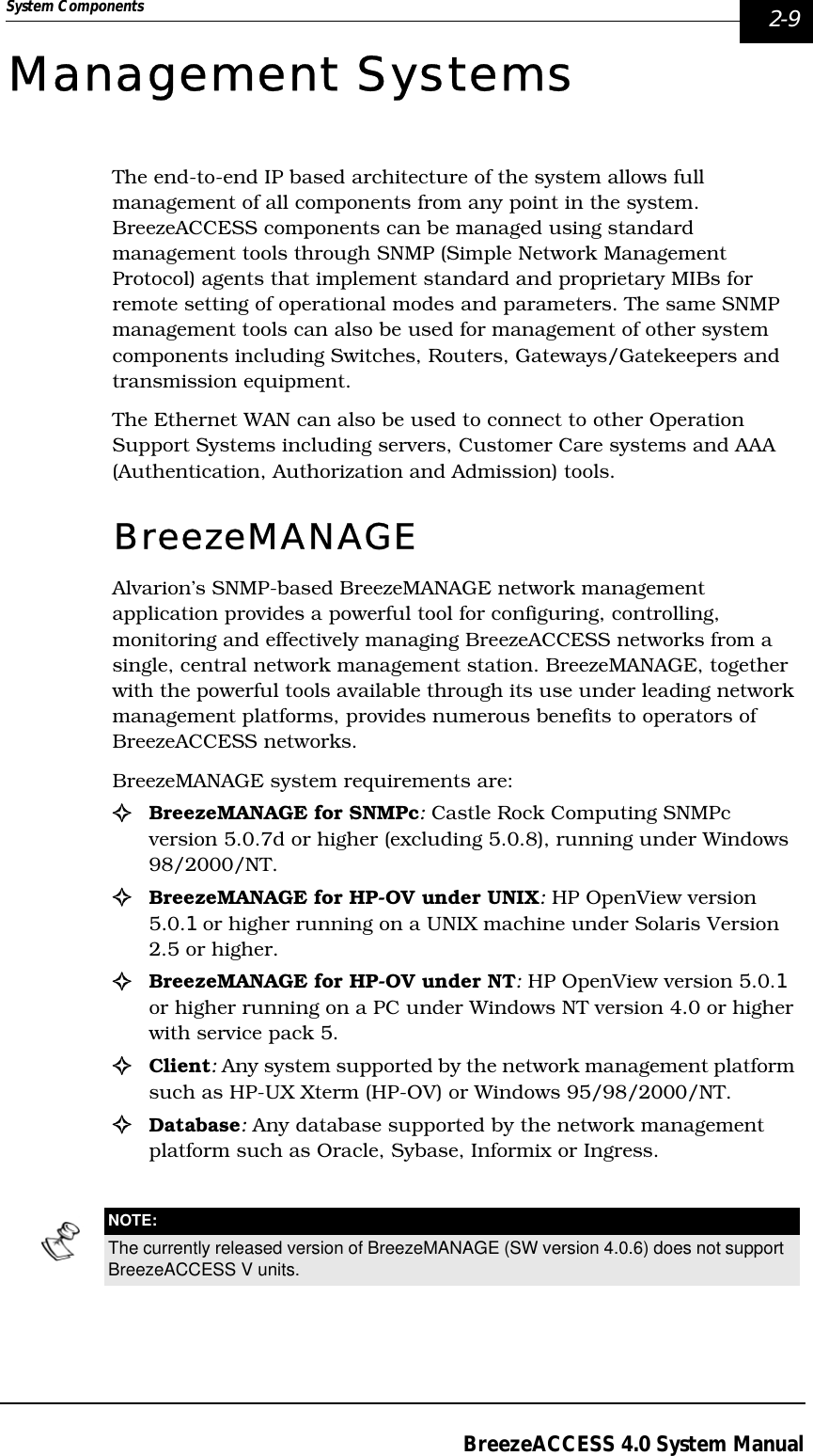
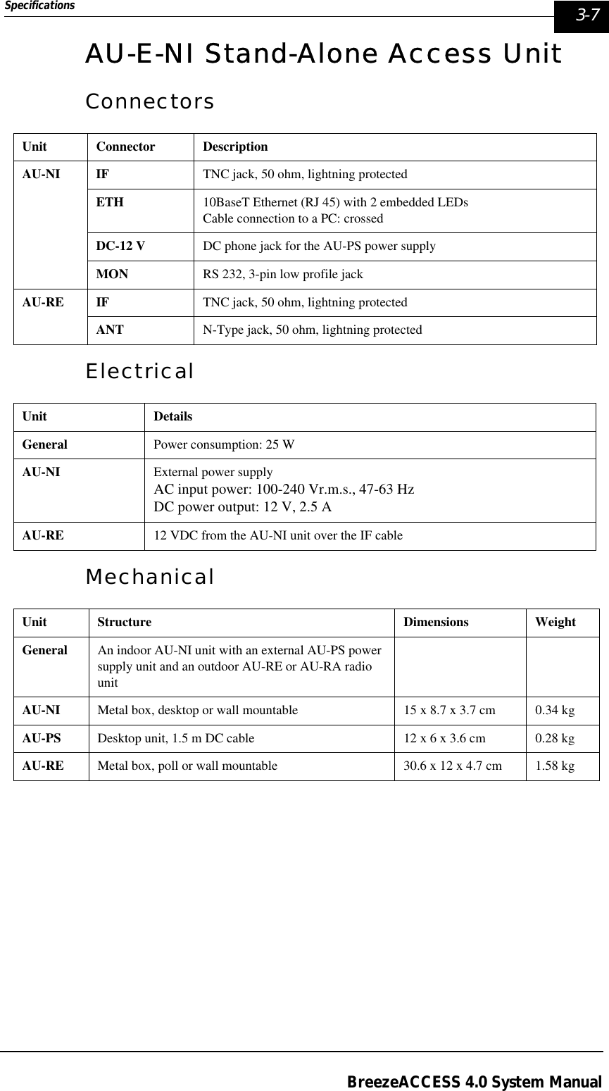

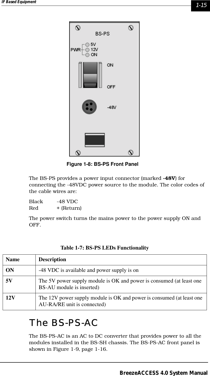
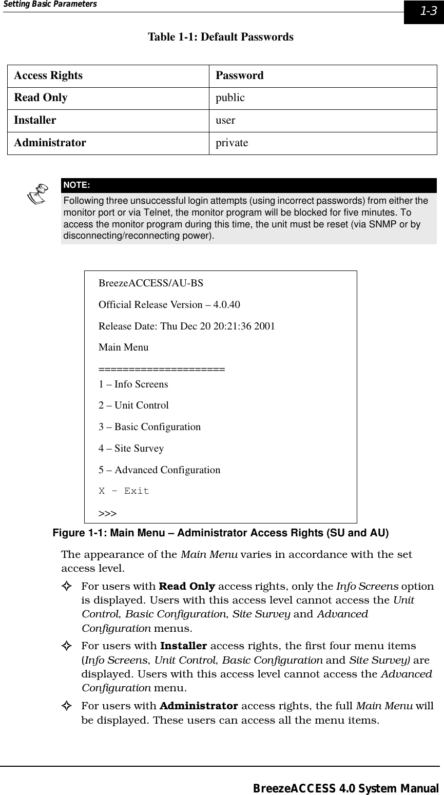
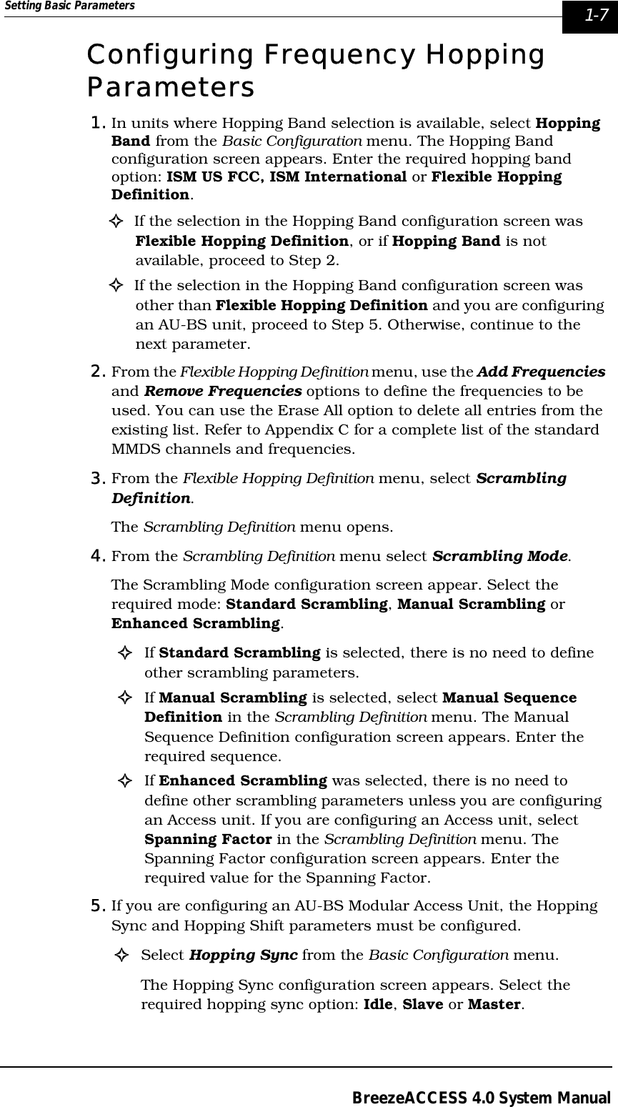
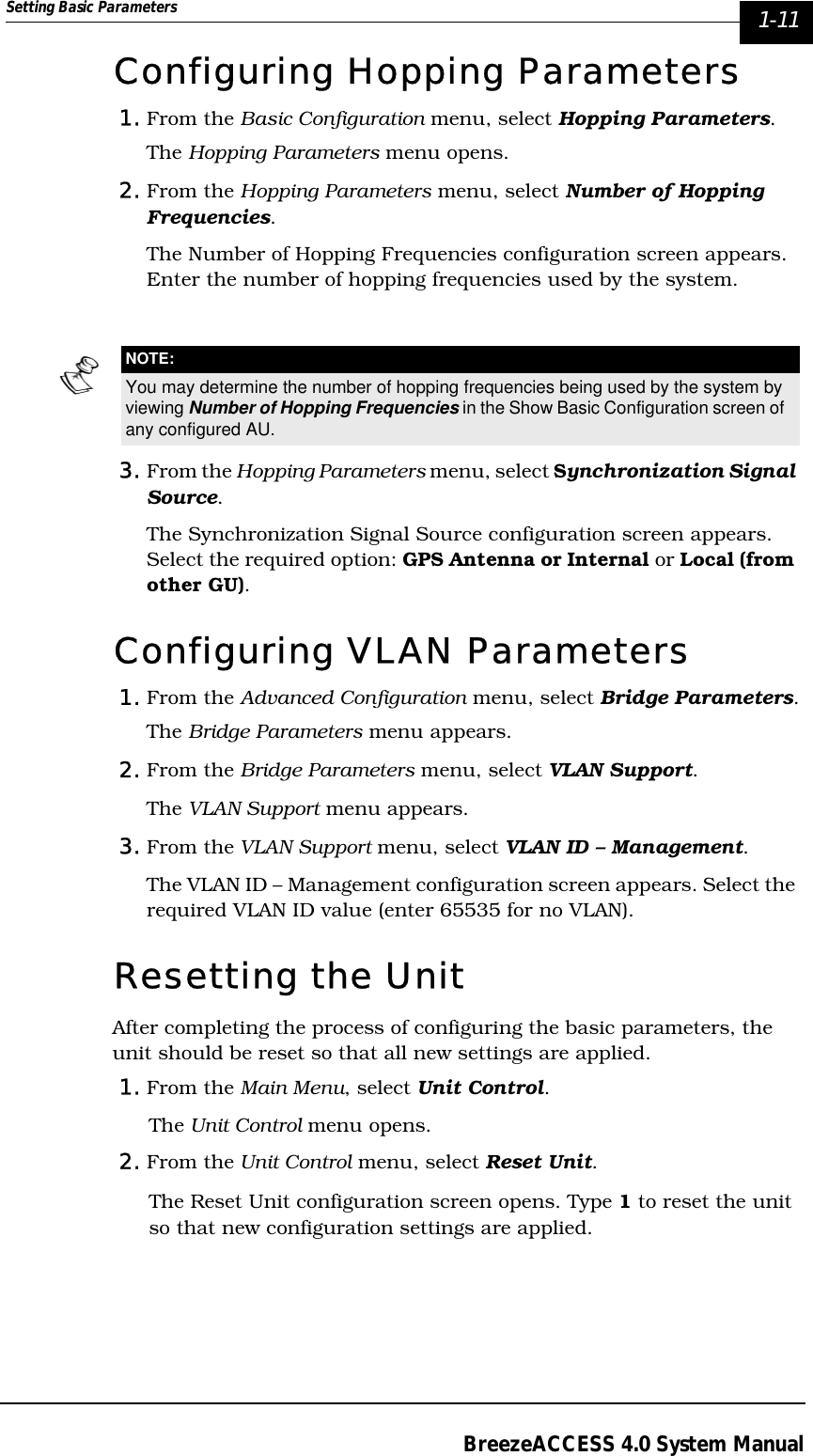


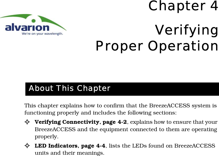
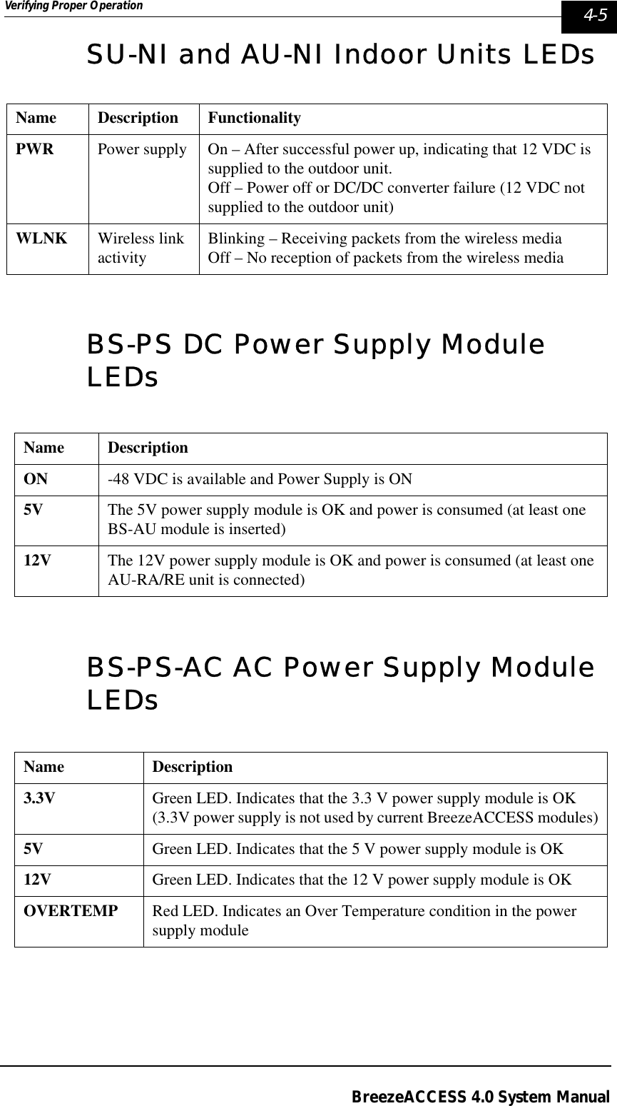
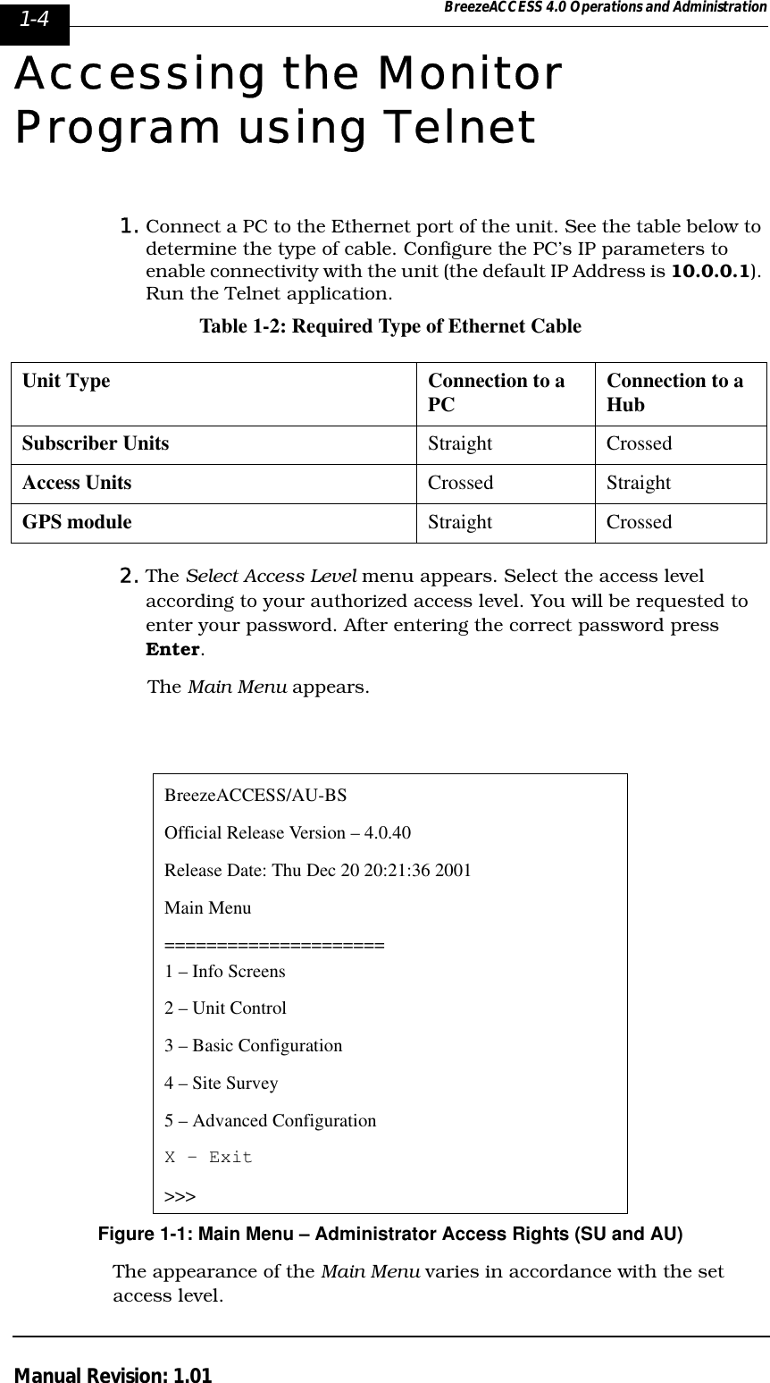
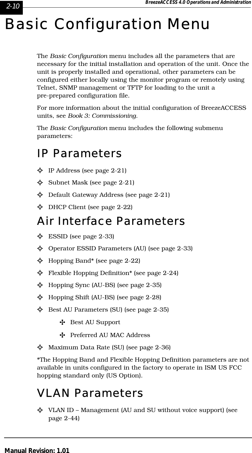
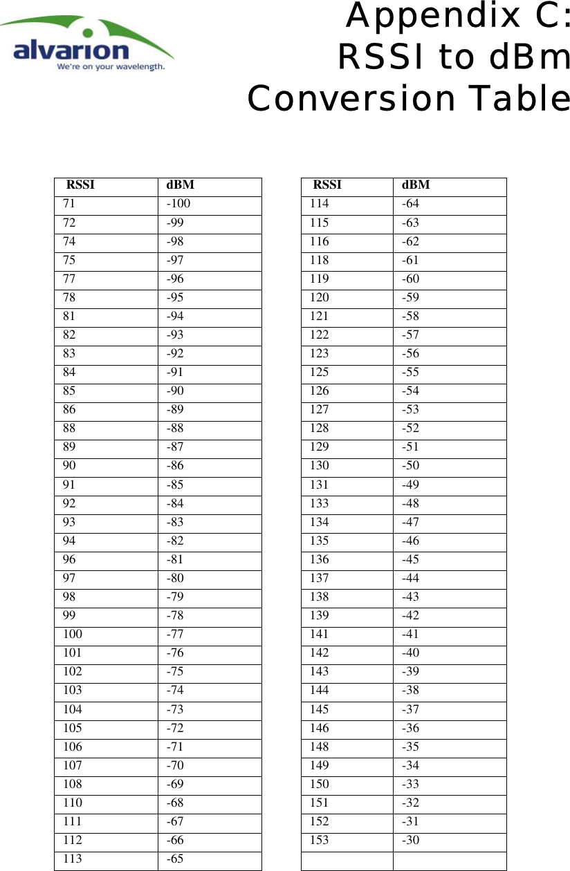
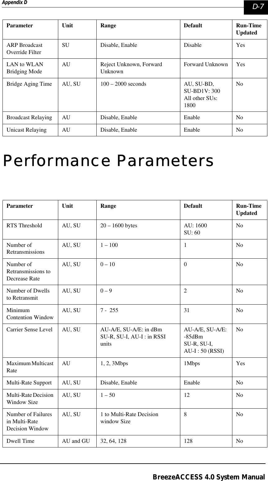
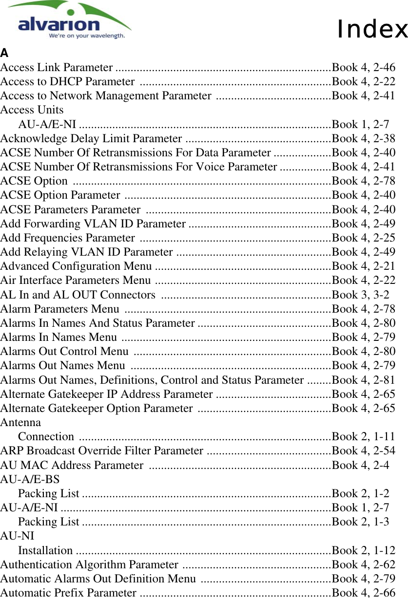
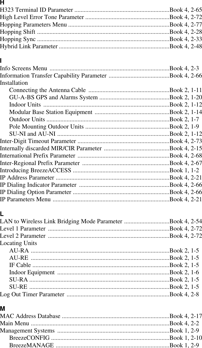
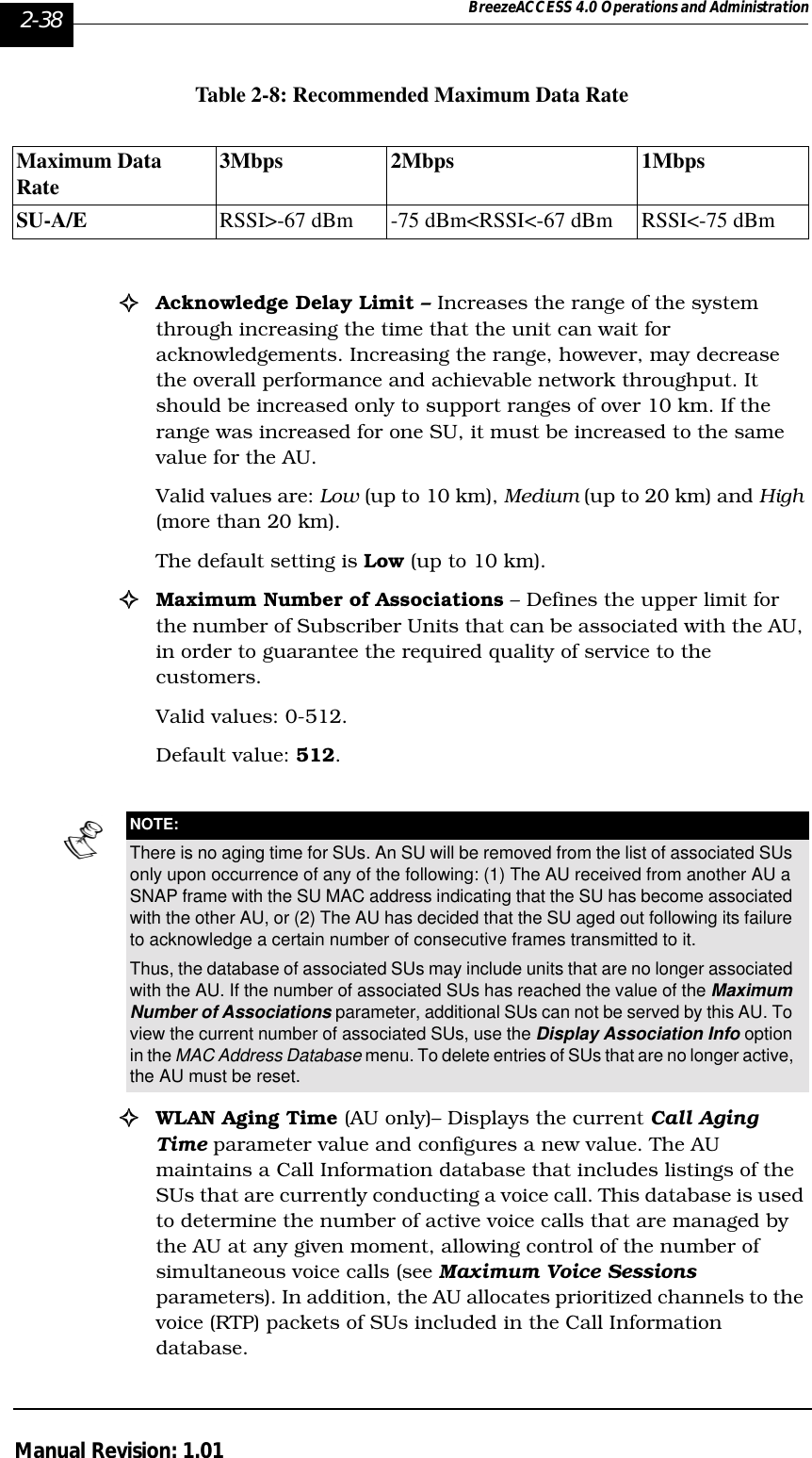
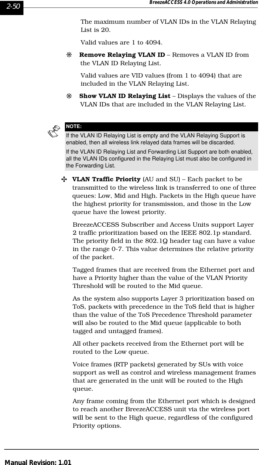
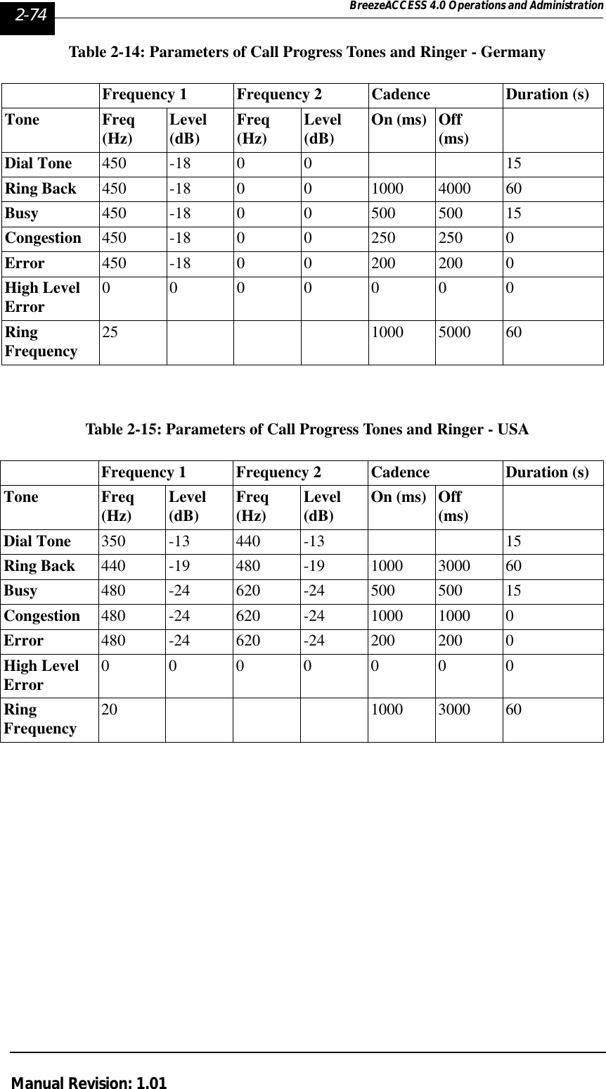
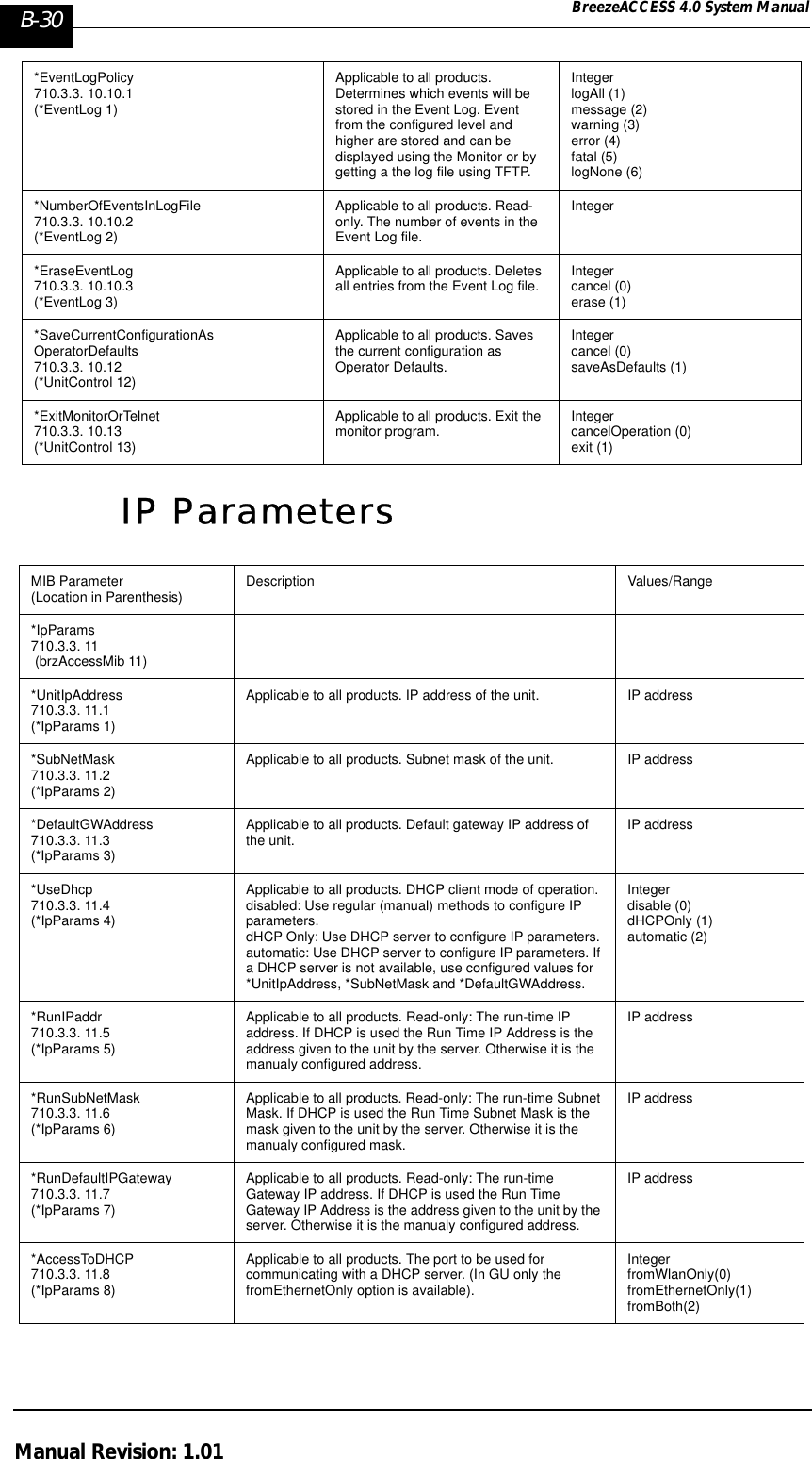
![2-26 BreezeACCESS 4.0 Operations and AdministrationManual Revision: 1.01parameter (see below) must be configured in the AU. The Enhanced Mode is not suitable for sequences with 6 or less frequencies. If Enhanced Scrambling is selected with sequences that have 6 or less frequencies, than Standard Scrambling is used by default. The scrambled sequence is generated according to the following rules:a.The first channel in the basic scrambled sequence is frequency 1 (Frequency 1 (index=1) is the lowest frequency in the list of frequencies to be used, frequency 2 is the next frequency and so on.)b.The index of each of the other channels is calculated by adding the Spanning Factor to the index of the previous channel. Note that the sequence is cyclic, meaning that adding 1 to the highest index in the sequence (Index=N where N is the number of channels in the sequence) will result in the first channel (Index=1). The scrambled basic sequence can also be calculated using the following formula:Px (j)= {[(j-1)*X]mod(N)}+1Where:X is the Spanning FactorN is the number of channels in the sequence (modulus)J is the sequence indexExample: N=8, X=3P1(5)={[(1-1)*3}mod8}+1=1P2(5)={[(2-1)*3}mod8}+1=6P3(5)={[(3-1)*3}mod8}+1=3P4(5)={[(4-1)*3}mod8}+1=8P5(5)={[(5-1)*3}mod8}+1=5P6(5)={[(6-1)*3}mod8}+1=2P7(5)={[(7-1)*3}mod8}+1=7P8(5)={[(8-1)*3}mod8}+1=4And the basic scrambled sequence is: 1, 4, 7, 2, 5, 8, 3, 6.#Manual Sequence Definition – Manually defines the hopping sequence, using numbered channel indexes (from 1 to “Number of Hopping Frequencies”). The sequence length must be equal to “Number of Hopping Frequencies” (all the defined frequencies must be used).#Erase Manual Sequence – Erases the manually defined hopping sequence.](https://usermanual.wiki/Alvarion-Technologies/IF-57/User-Guide-255470-Page-132.png)
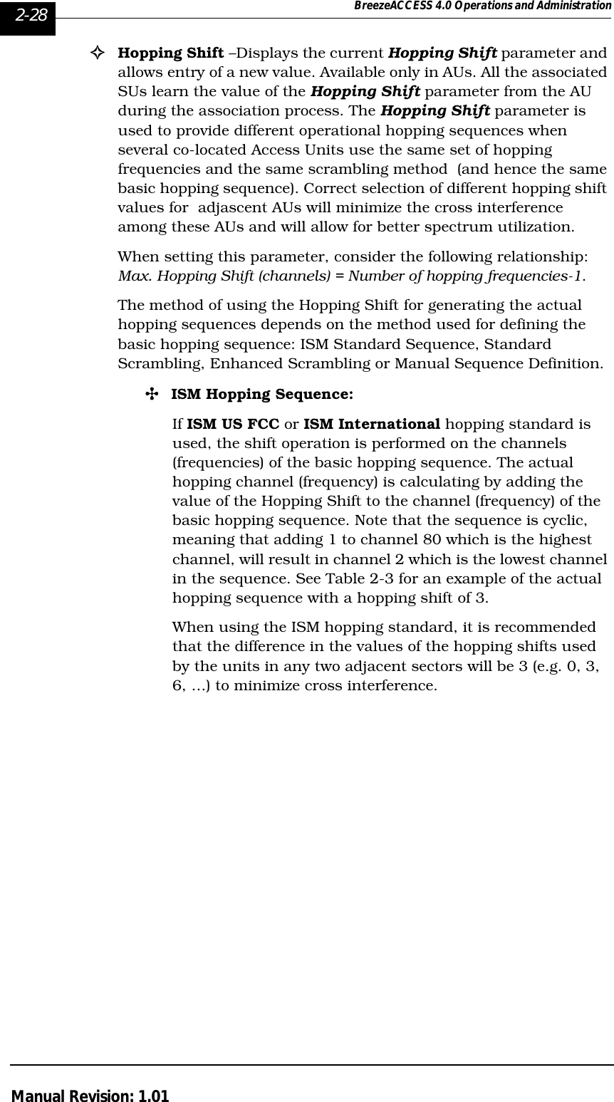
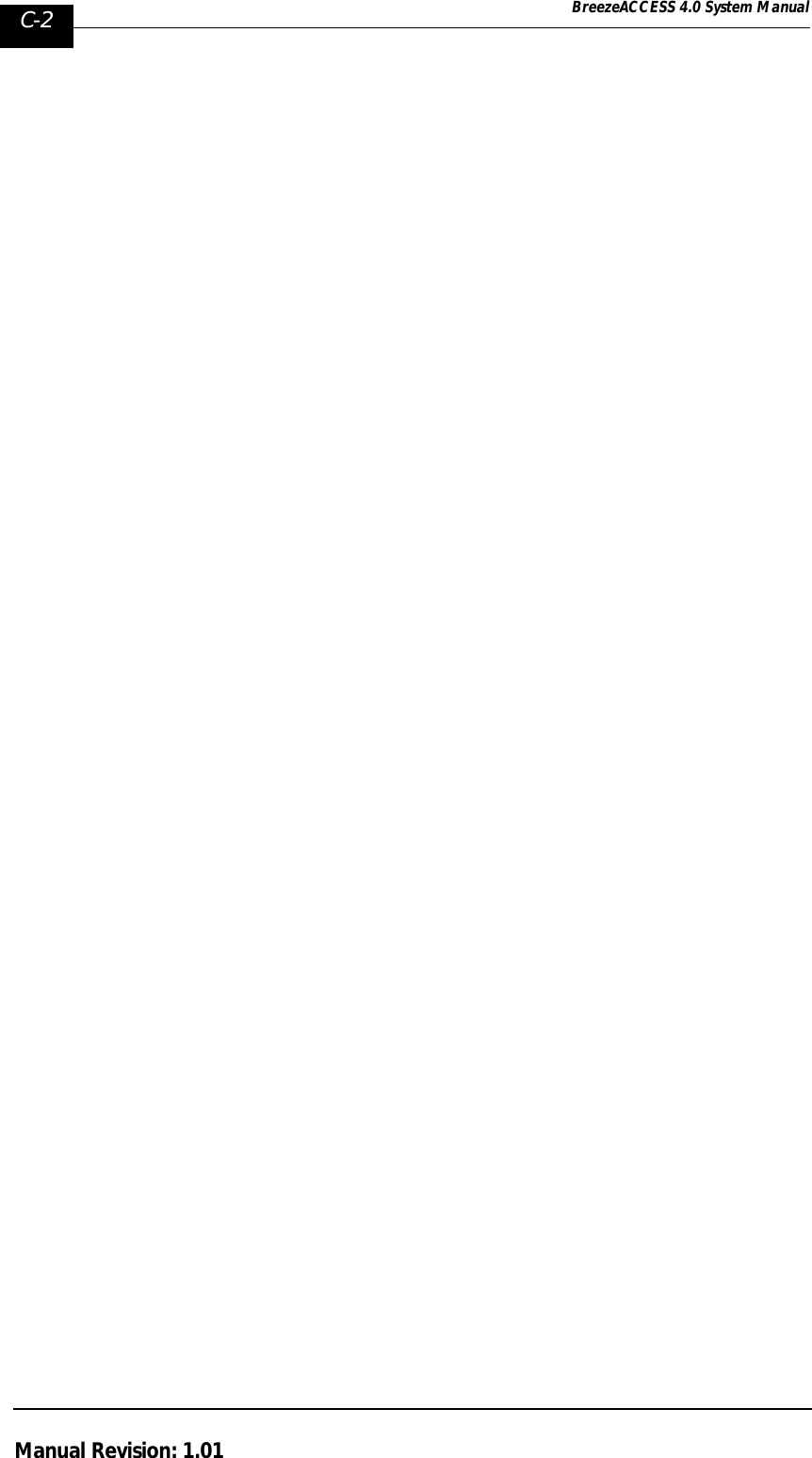
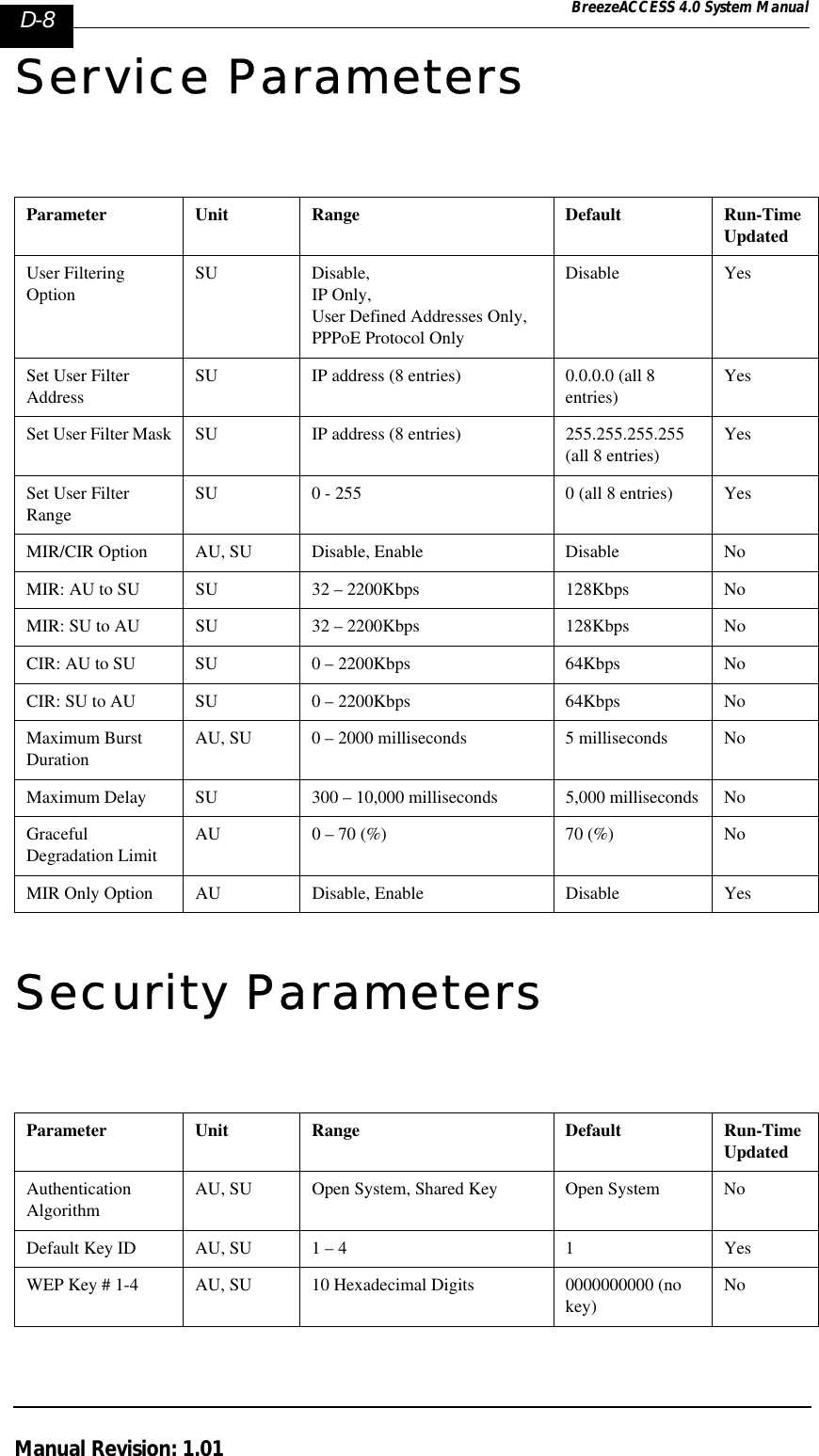
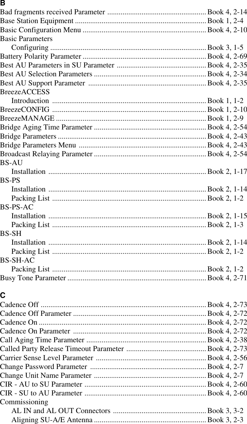
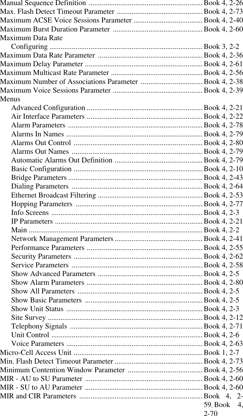
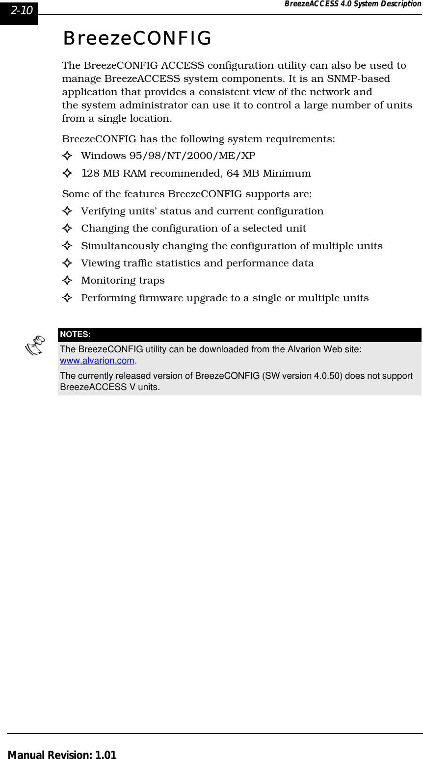
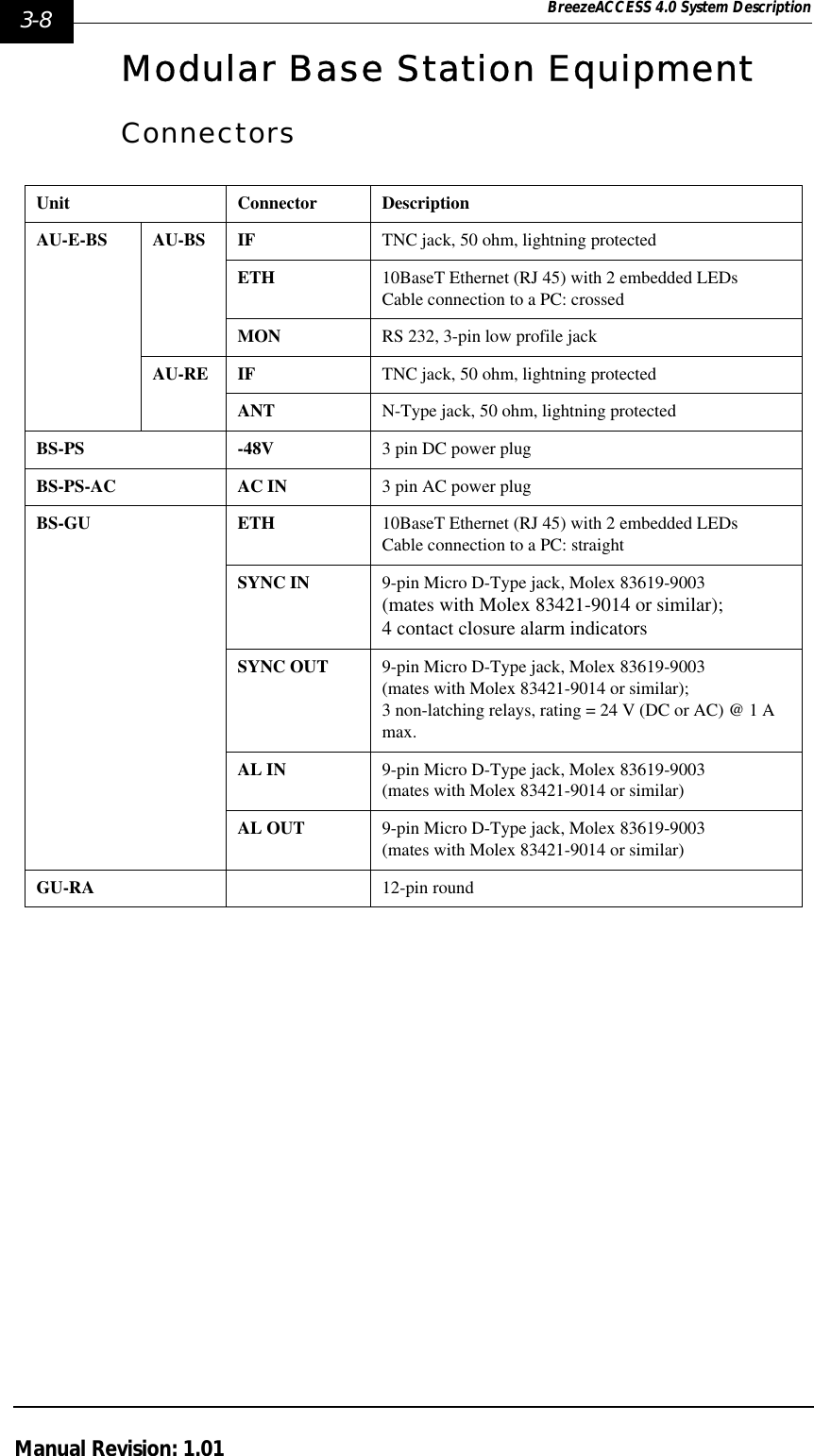
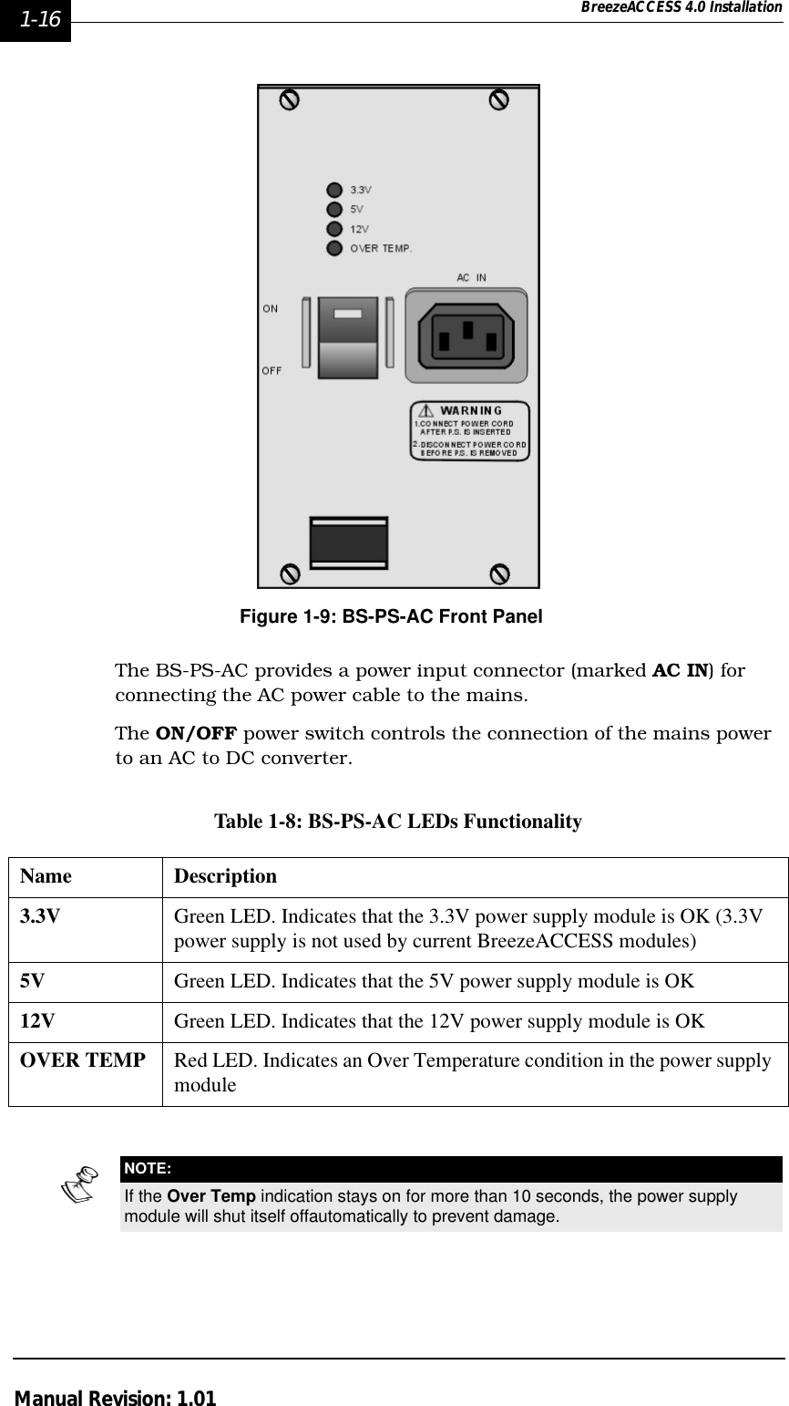
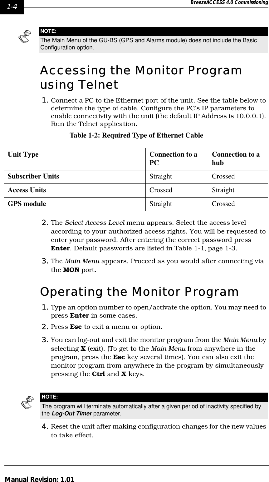
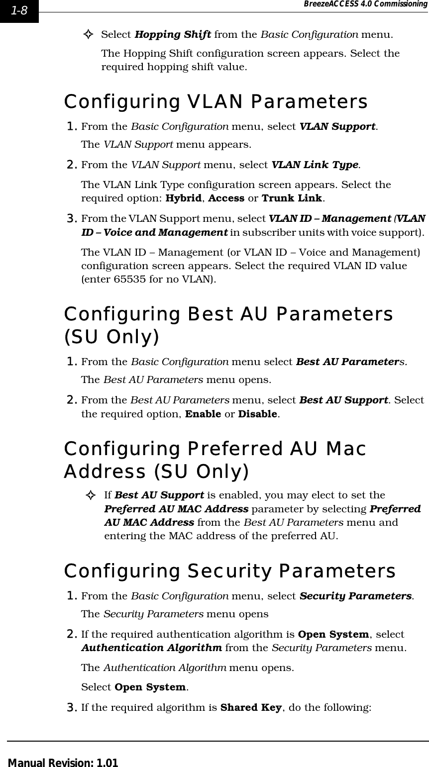
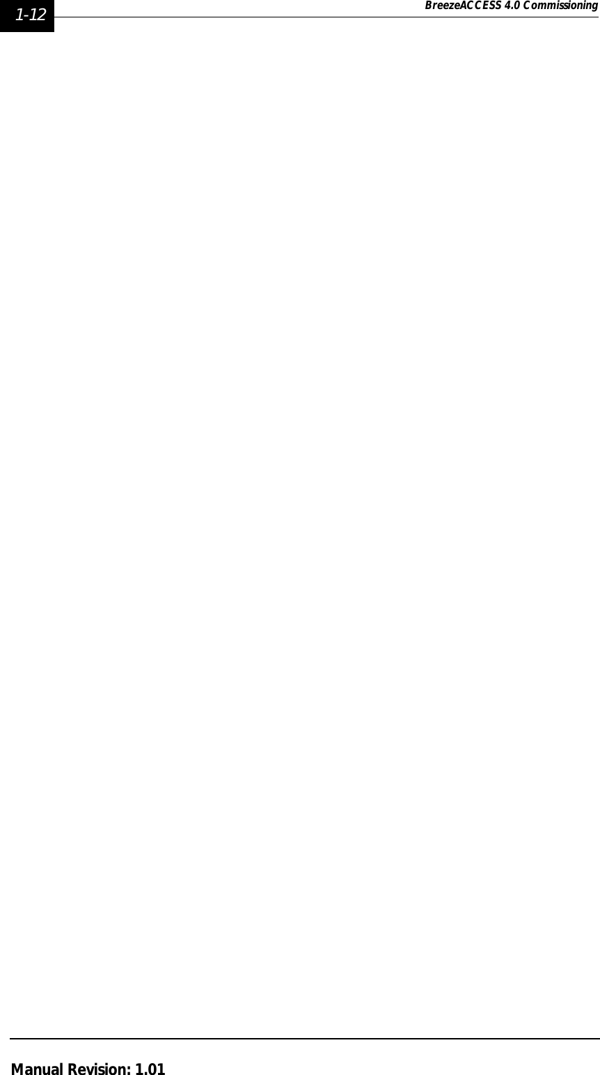
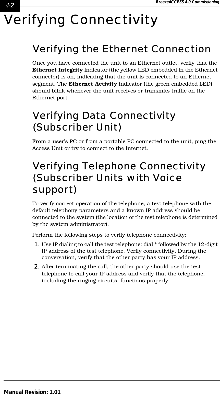
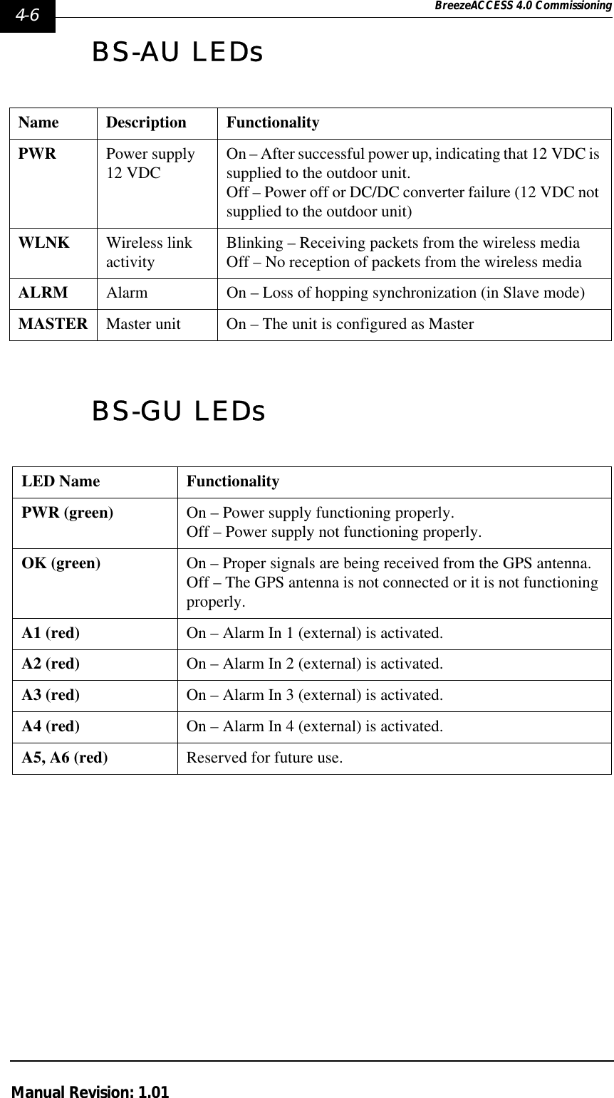
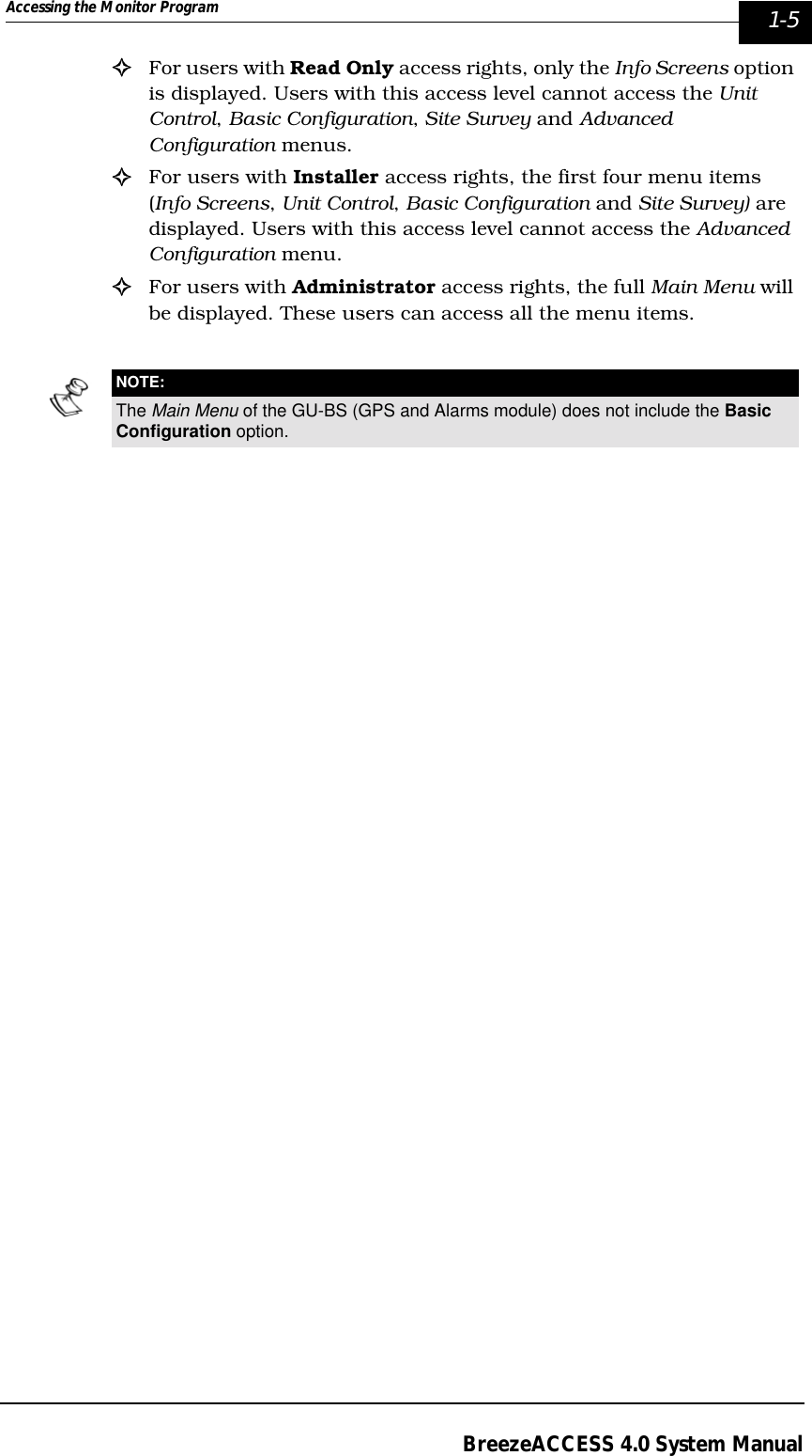
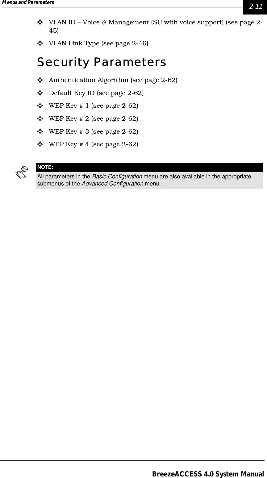
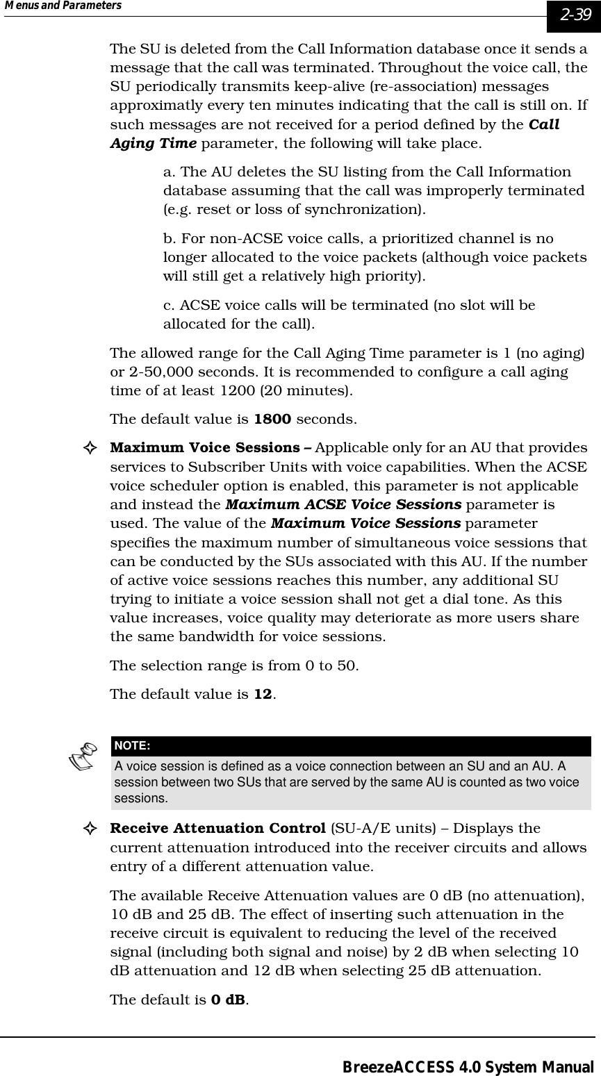
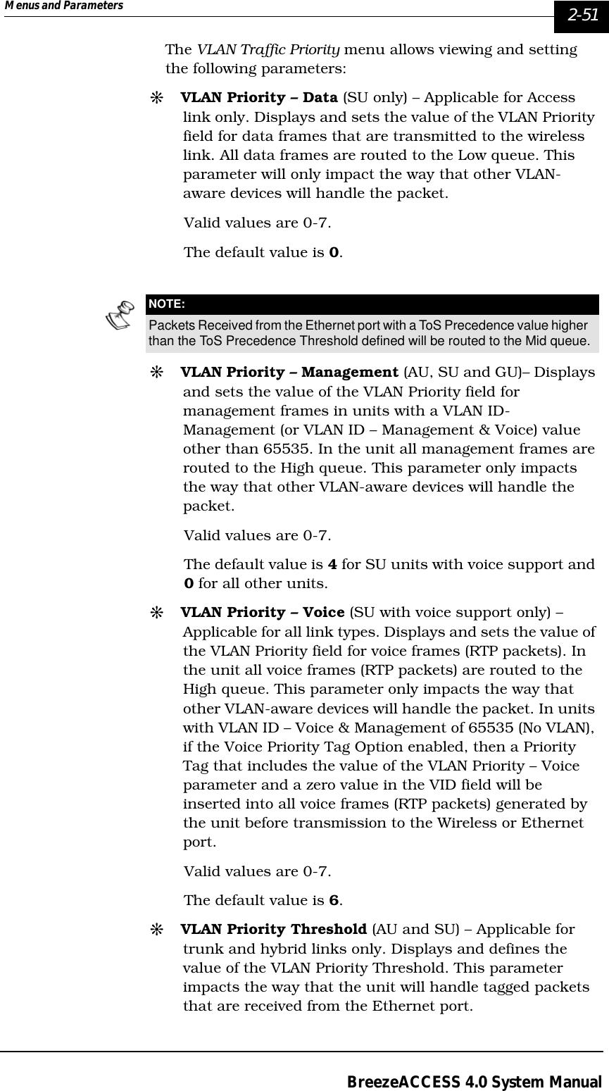
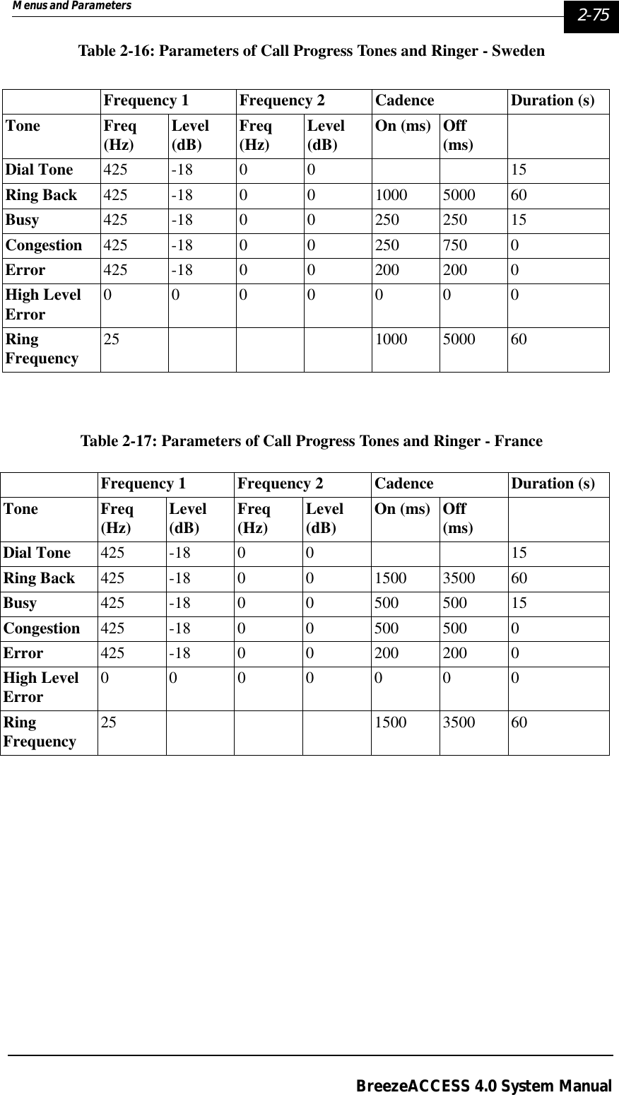
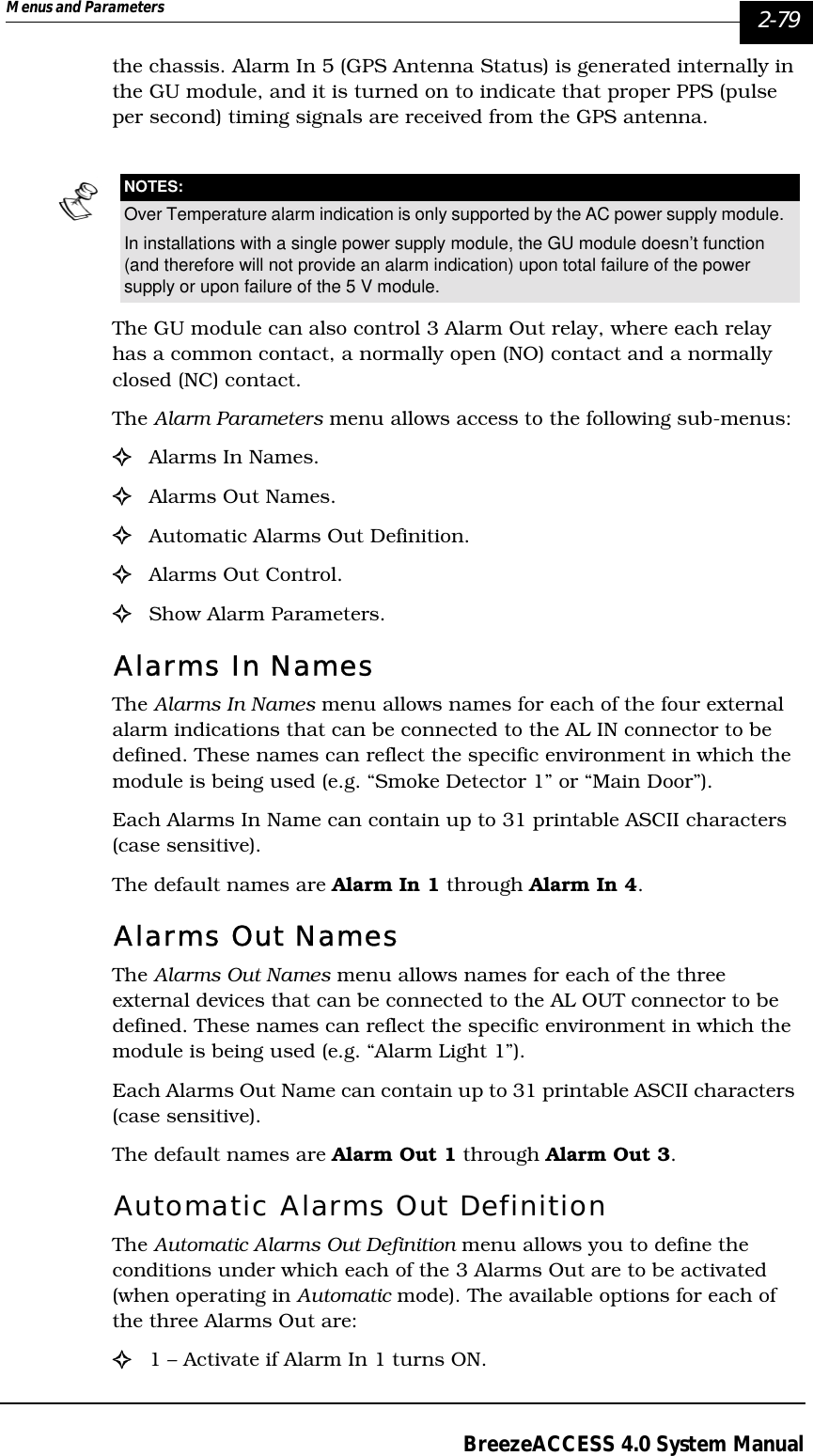
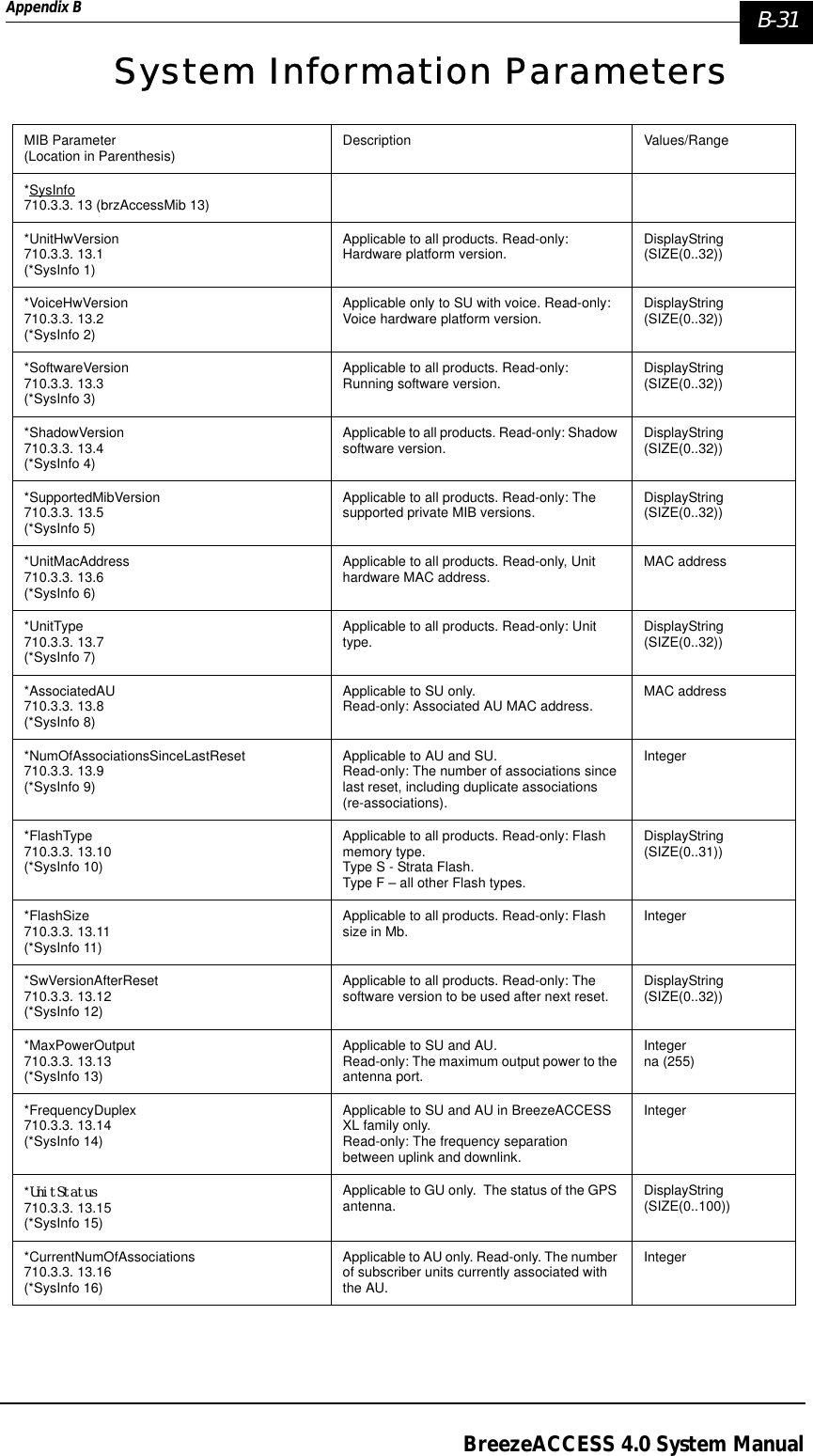
![2-30 BreezeACCESS 4.0 Operations and AdministrationManual Revision: 1.01(Index=N where N is the number of channels in the sequence) will result in the first channel (Index=1). Example: Enhanced Scrambling, N=8, Spanning Factor=3:Table 2-4: Hopping Shift Implementation, Enhanced Scrambling (N=8, Spanning Factor=3)If for example the defined hopping frequencies are 5730, 5740, 5750, 5760, 5770, 5780, 5790, 5800, then the frequencies of the actual hopping sequences are:Table 2-5: Actual Hopping sequences, Enhanced Scrambling (N=8, Spanning Factor=3)The following formula can be used for calculating the actual hopping sequence: PS(j)={[P0(j)+S-1]mod(N)}+1 Where:S=Hopping ShiftHopping Shift Actual Sequence Indexes0 (basic sequence) 1, 4, 7, 2, 5, 8, 3, 612, 5, 8, 3, 6, 1, 4, 723, 6, 1, 4, 7, 2, 5, 834, 7, 2, 5, 8, 3, 6, 145, 8, 3, 6, 1, 4, 7, 256, 1, 4, 7, 2, 5, 8, 367, 2, 5, 8, 3, 6, 1, 478, 3, 6, 1, 4, 7, 2, 5Hopping Shift Hop#1 Hop#2 Hop#3 Hop#4 Hop#5 Hop#6 Hop#7 Hop#805730 5760 5790 5740 5770 5800 5750 578015740 5770 5800 5750 5780 5730 5760 579025750 5780 5730 5760 5790 5740 5770 580035760 5790 5740 5770 5800 5750 5780 573045770 5800 5750 5780 5730 5760 5790 574055780 5730 5760 5790 5740 5770 5800 575065790 5740 5770 5800 5750 5780 5730 576075800 5750 5780 5730 5760 5790 5740 5770](https://usermanual.wiki/Alvarion-Technologies/IF-57/User-Guide-255470-Page-136.png)
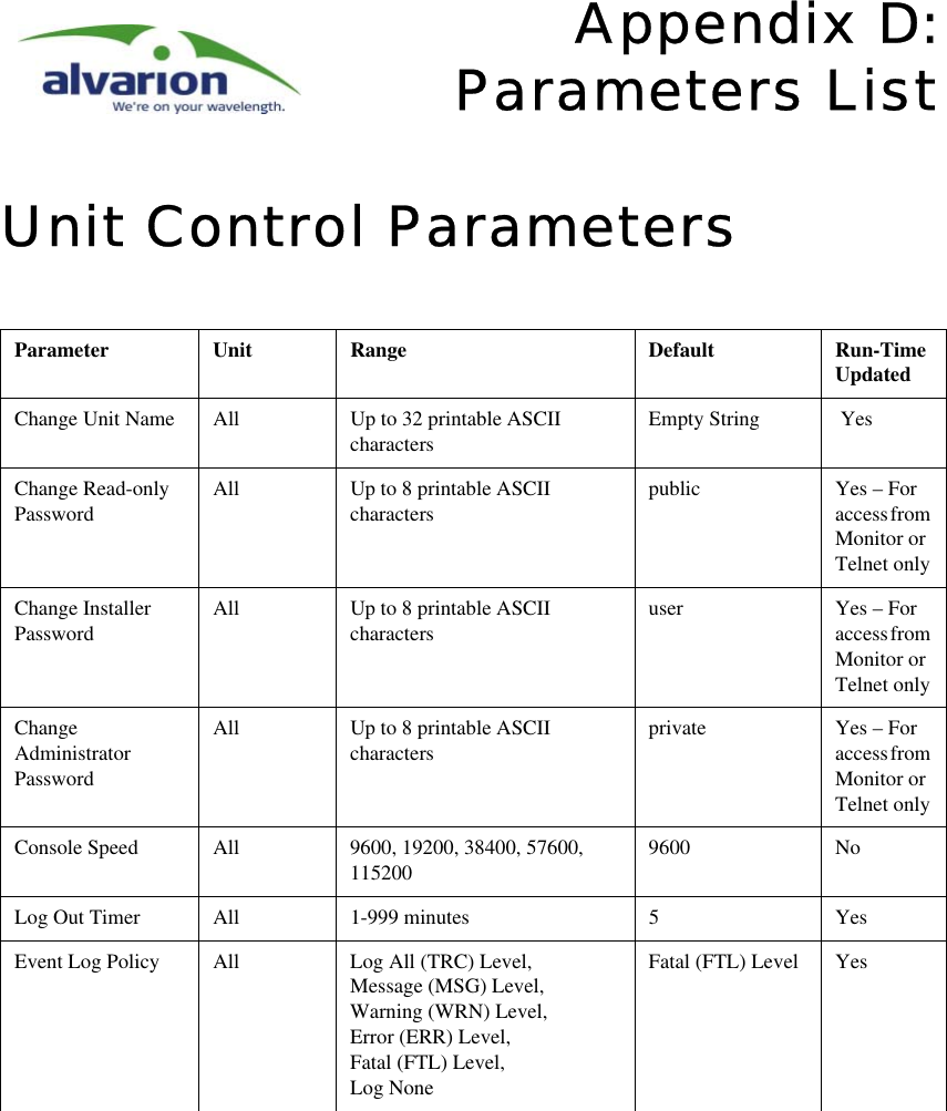
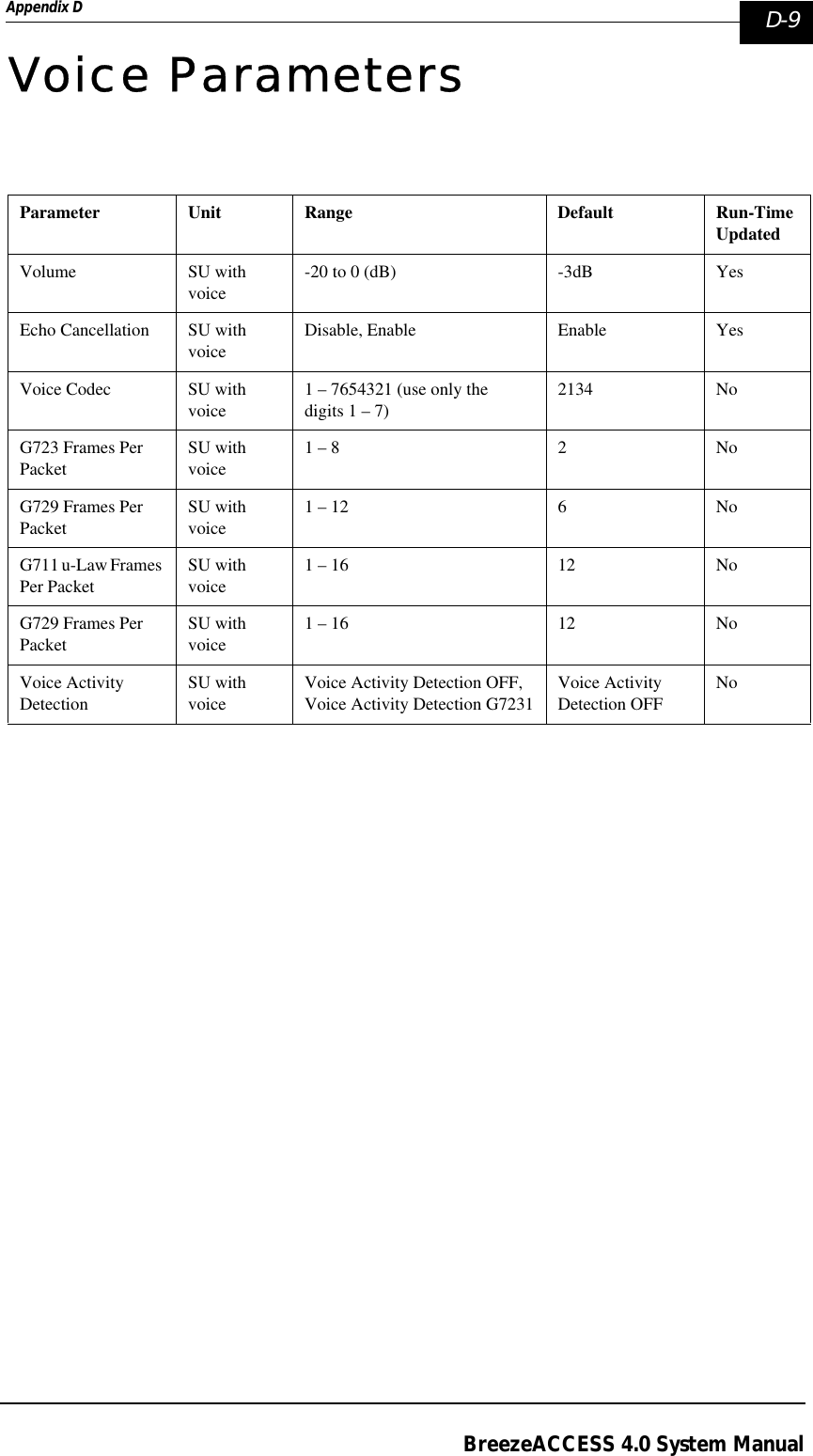
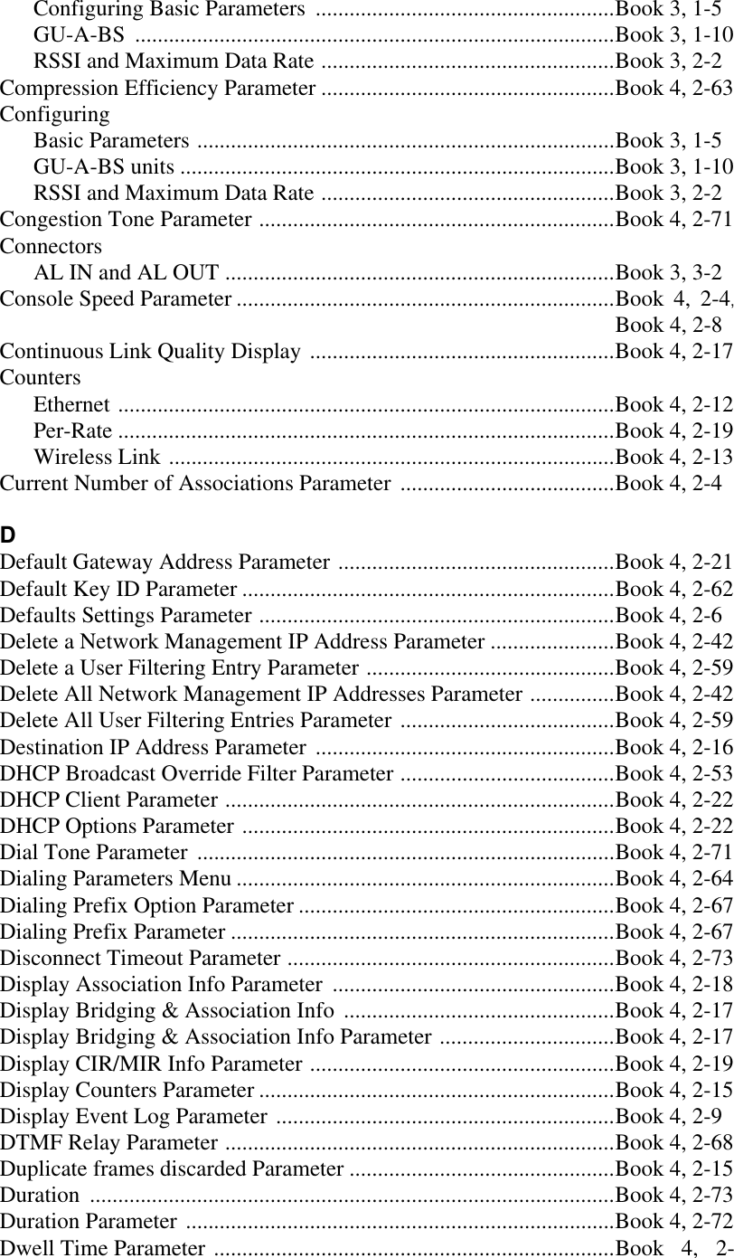
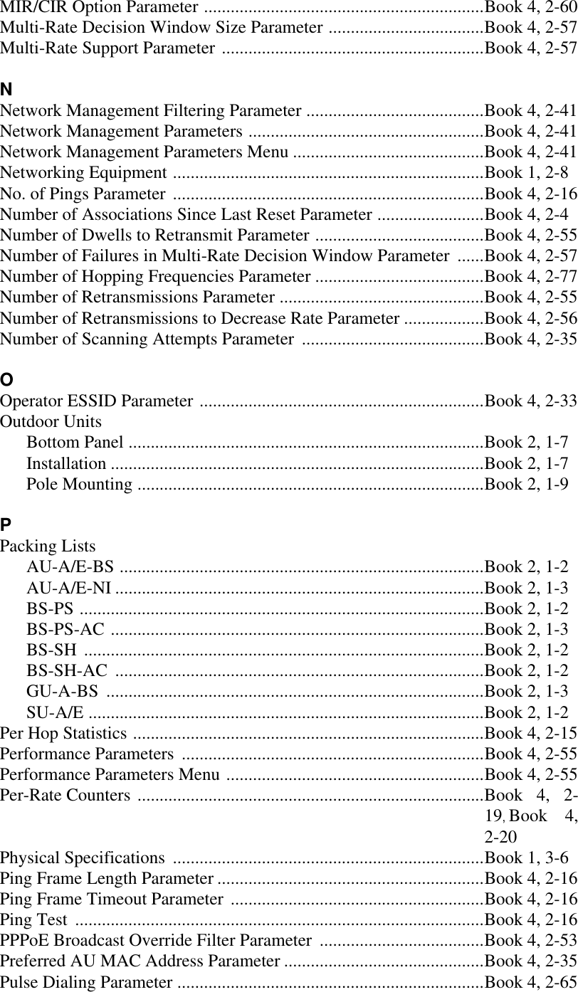
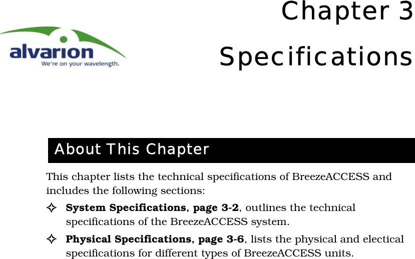
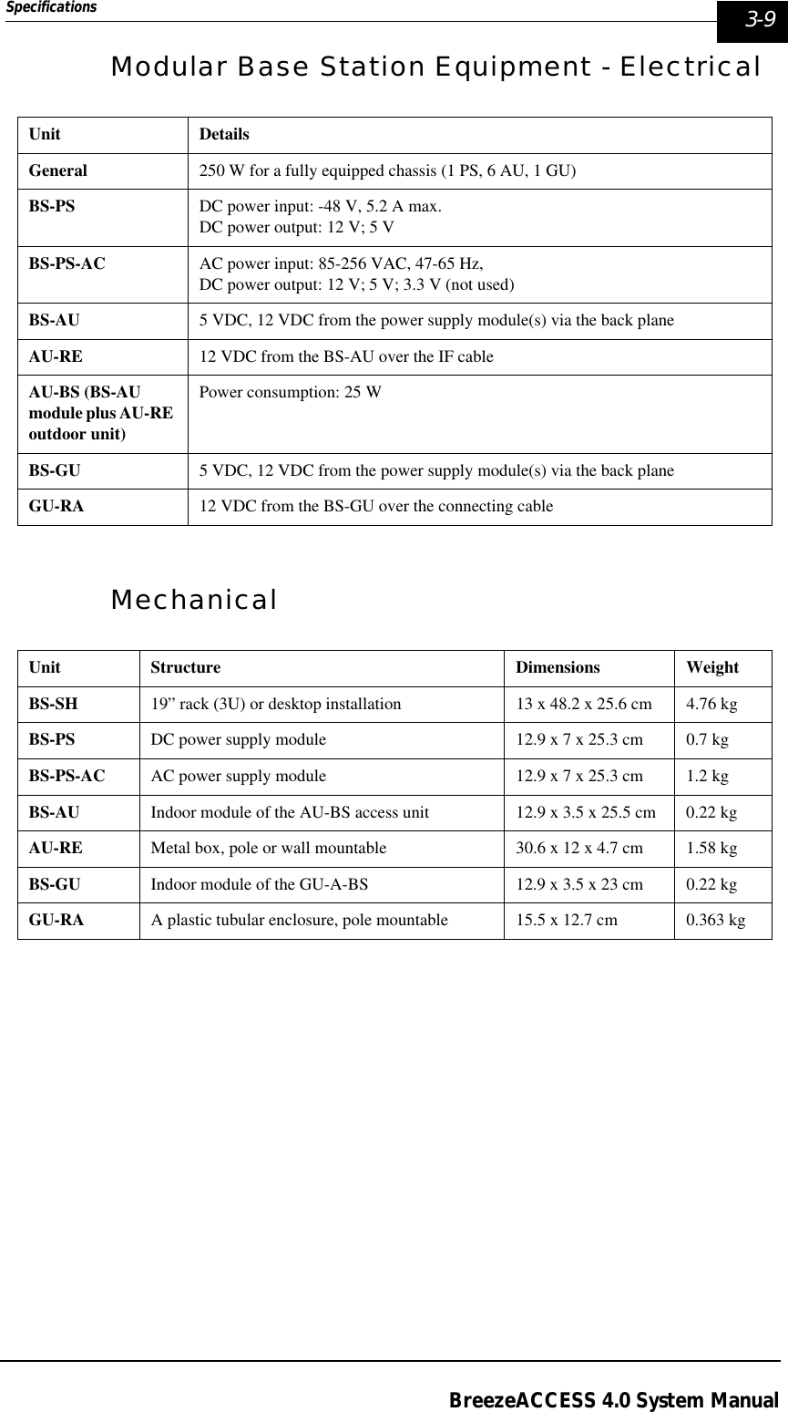
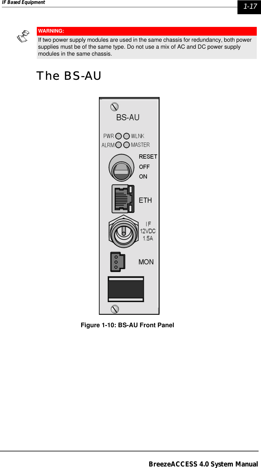
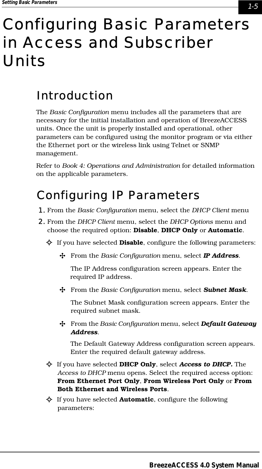
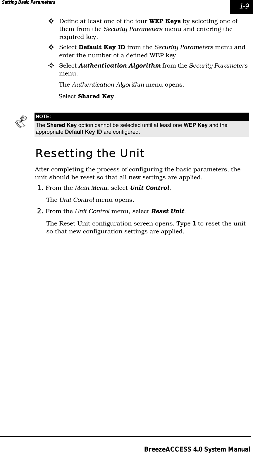
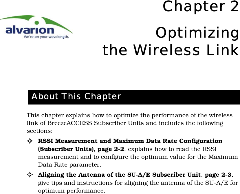
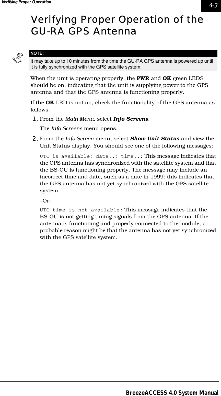
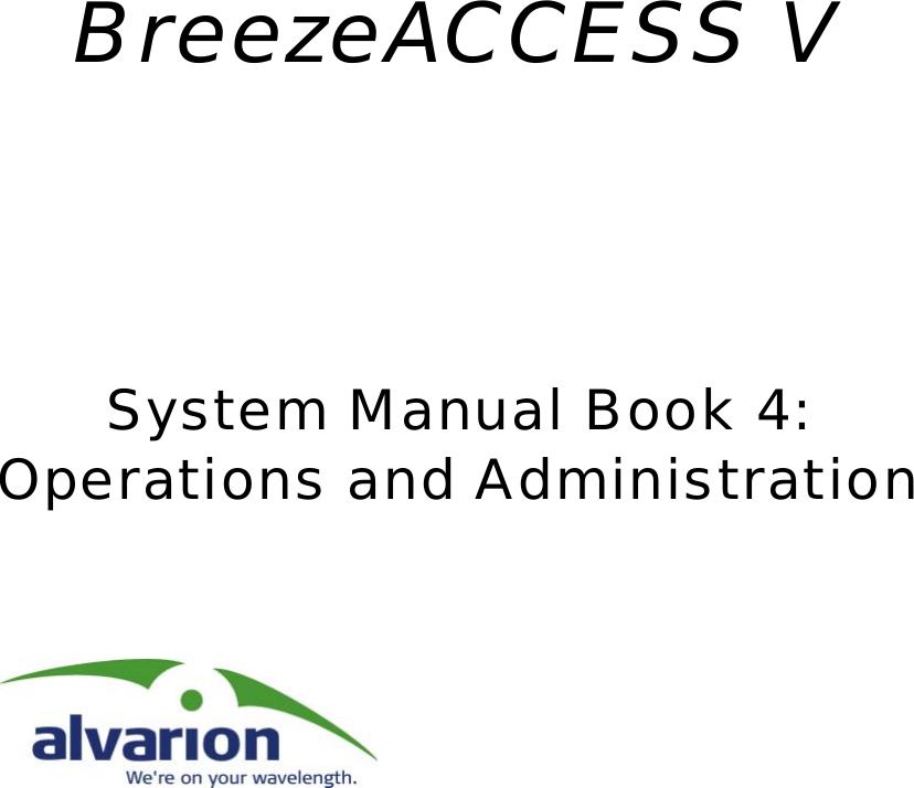
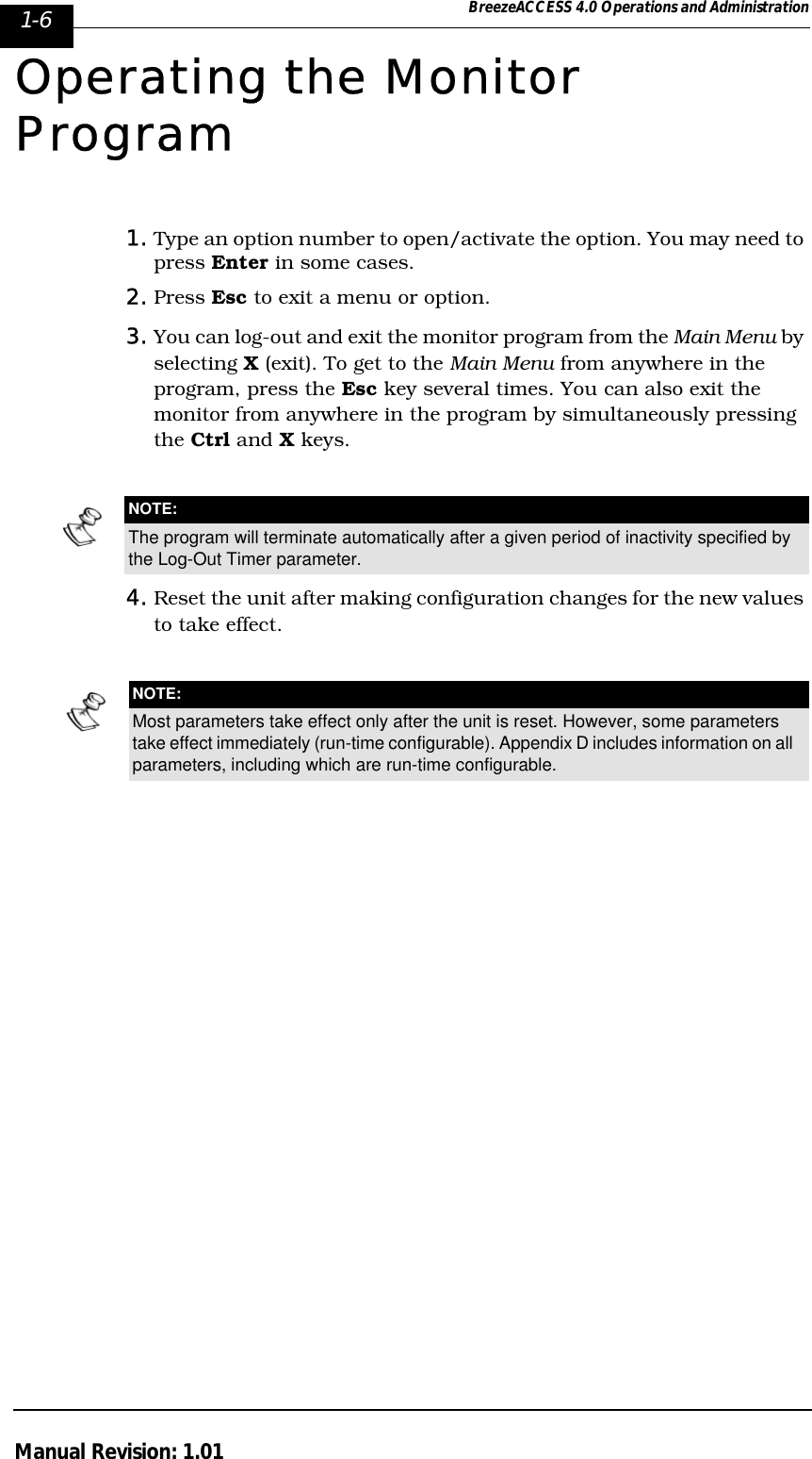
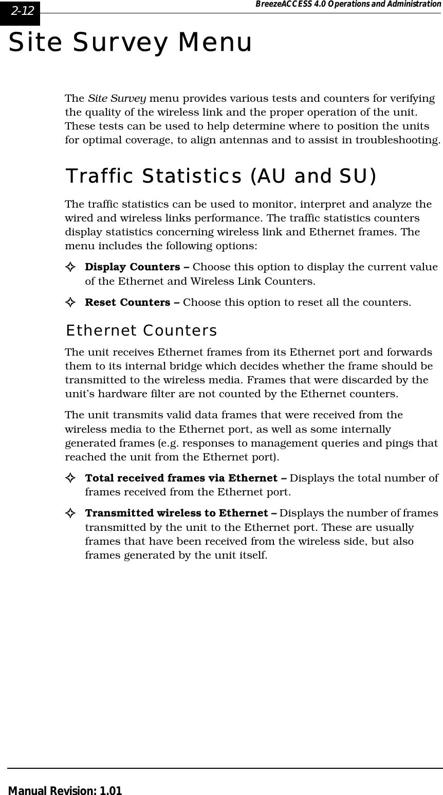
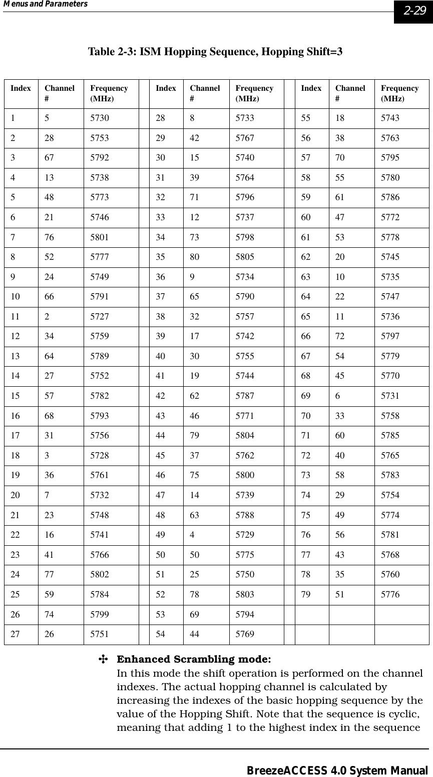
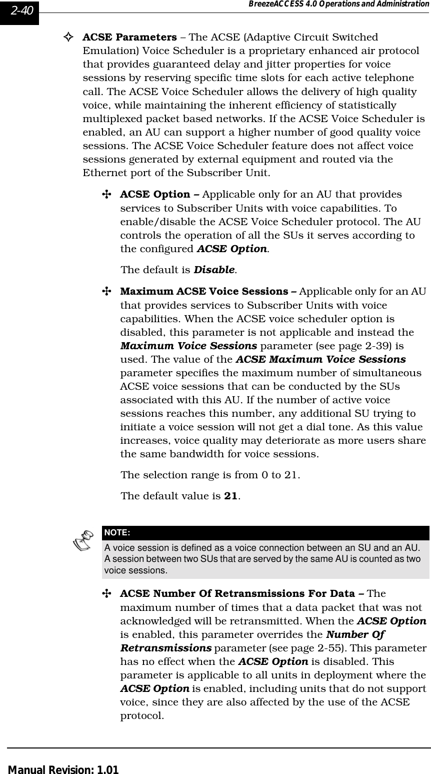
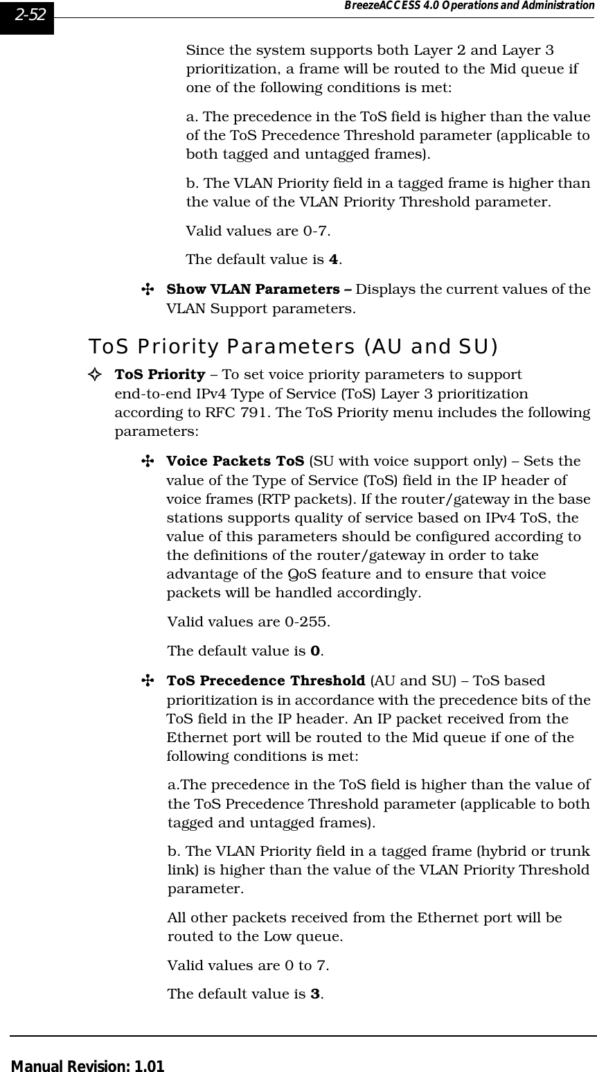
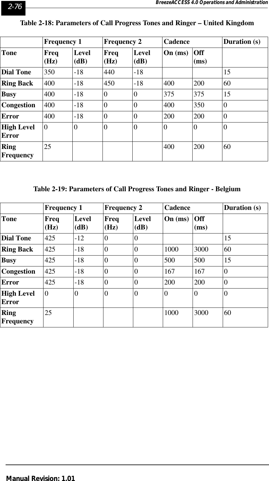
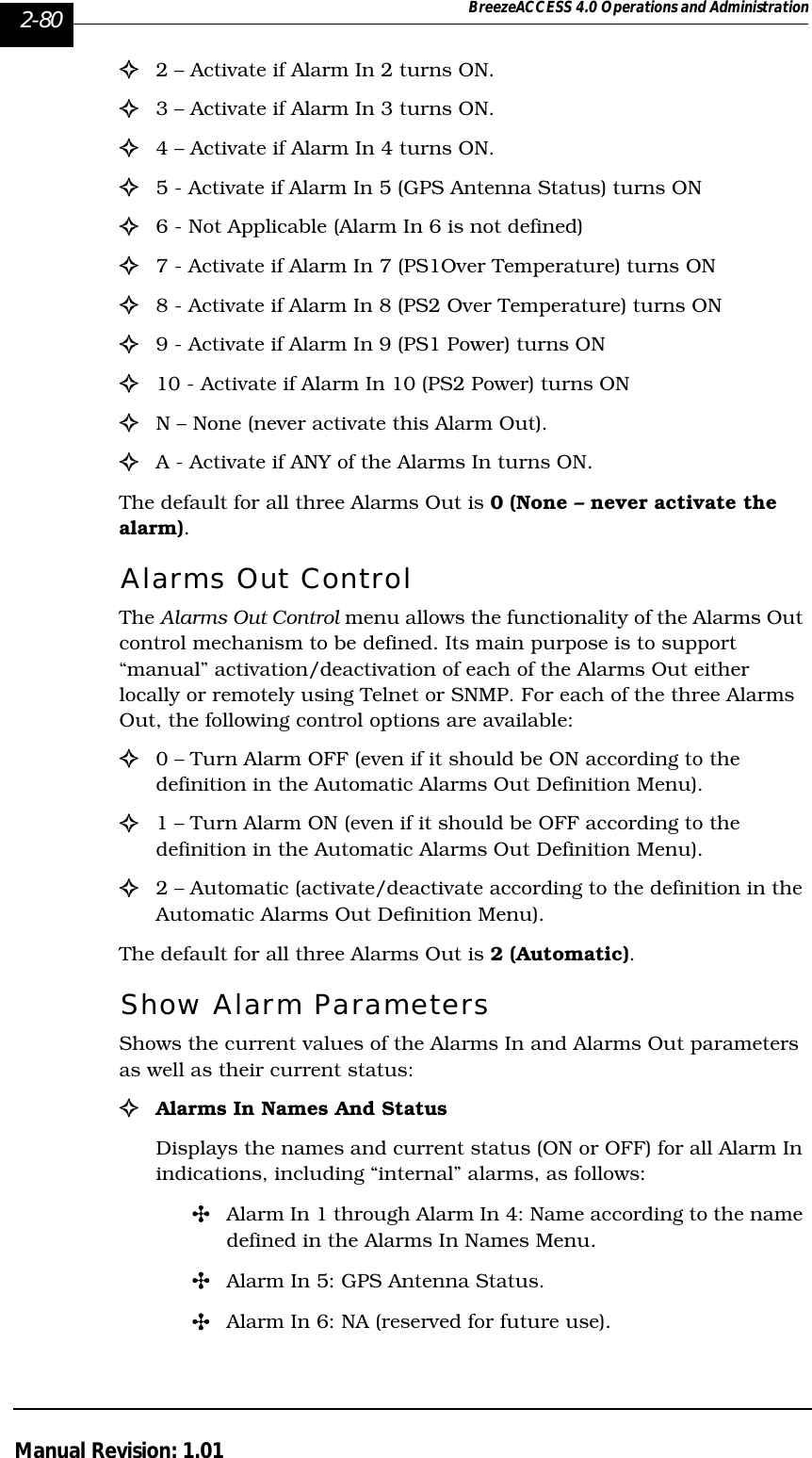
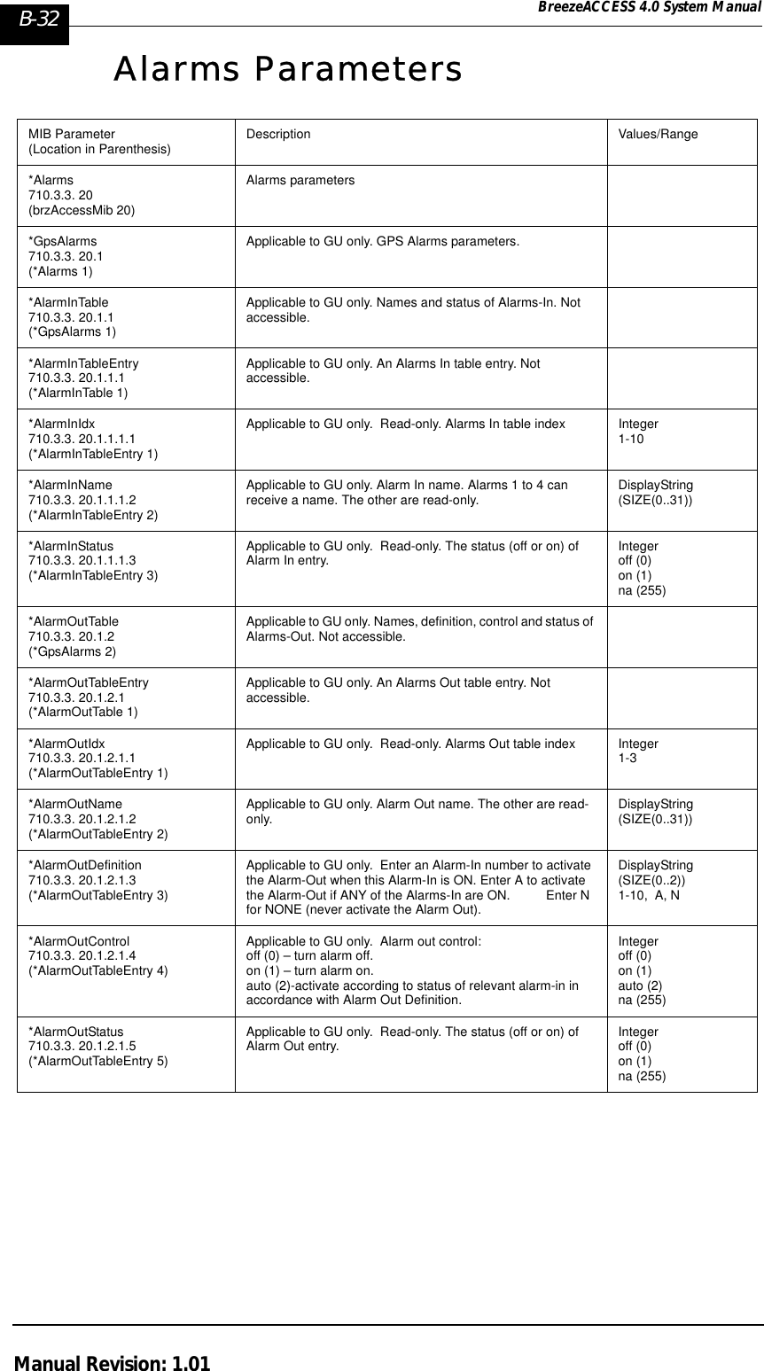
![Menus and Parameters 2-31BreezeACCESS 4.0 System ManualN=number of channels in the sequence (modulus)P0(j)=Channel no. j in the basic sequence (shift=0)PS(j)=Channel no. j in the actual sequence with hopping shift SExample: The basic hopping sequence is 1, 4, 7, 2, 5, 8, 3, 6 (Enhanced Scrambling, N=8, Spanning Factor=3).The actual hopping sequence for a hopping shift of 3 is:P3(1)=[1+3-1]mod8+1=4P3(2)=[4+3-1]mod8+1=7P3(3)=[7+3-1]mod8+1=2P3(4)=[2+3-1]mod8+1=5P3(5)=[5+3-1]mod8+1=8P3(6)=[8+3-1]mod8+1=3P3(7)=[3+3-1]mod8+1=6P3(8)=[6+3-1]mod8+1=1The actual hopping sequence indexes are: 4, 7, 2, 5, 8, 3, 6, 1Standard and Manual Scrambling:In these modes the shift operation is performed on the sequence elements. The basic sequence is shifted cyclically according to the value of the Hopping Shift parameter, so that element no. i in the actual sequence equals element number i+s in the basic sequence, where s is the hopping shift. Thus, if the basic sequence is a, b, c, d, e, f then a shift of 1 will result in the sequence b, c, d, e, f, a,; a shift of 2 will result in the sequence c, d, e, f, a, b; and so forth. Example: Standard Scrambling, N=6Table 2-6: Hopping Shift Implementation, Standard Scrambling (N=6)If the defined frequencies are 5730, 5740, 5750, 5760, 5770, 5780, then the frequencies of the actual hopping sequences are:Hopping Shift Actual Sequence0 (basic sequence) 1, 3, 5, 2, 6, 413, 5, 2, 6, 4, 125, 2, 6, 4, 1, 332, 6, 4, 1, 3, 546, 4, 1, 3, 5, 254, 1, 3, 5, 2, 6](https://usermanual.wiki/Alvarion-Technologies/IF-57/User-Guide-255470-Page-137.png)
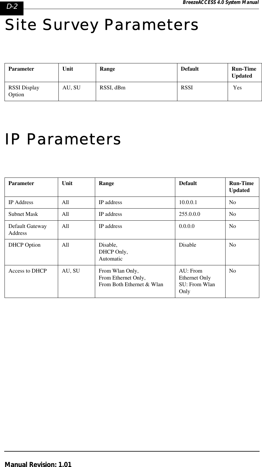
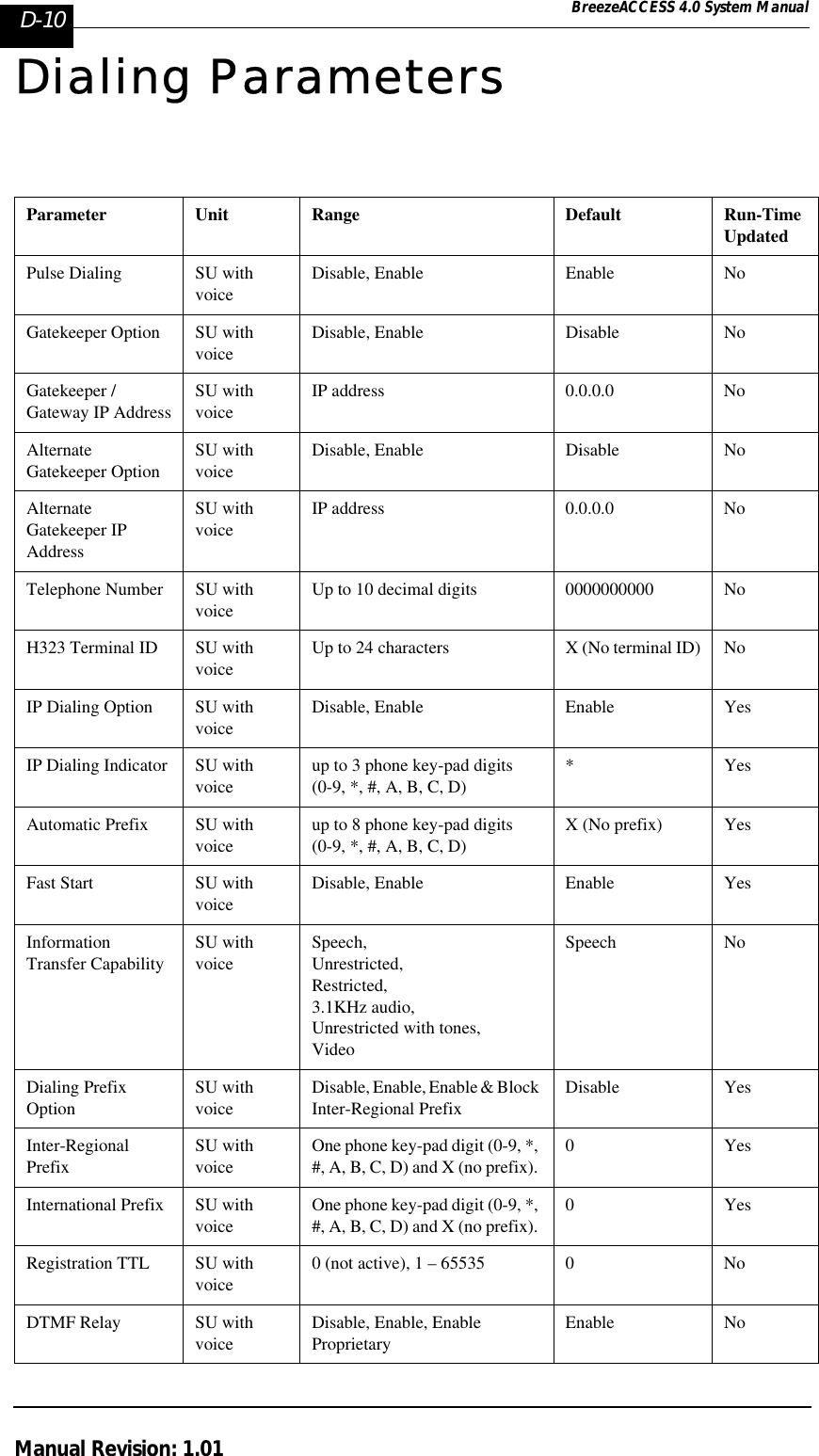
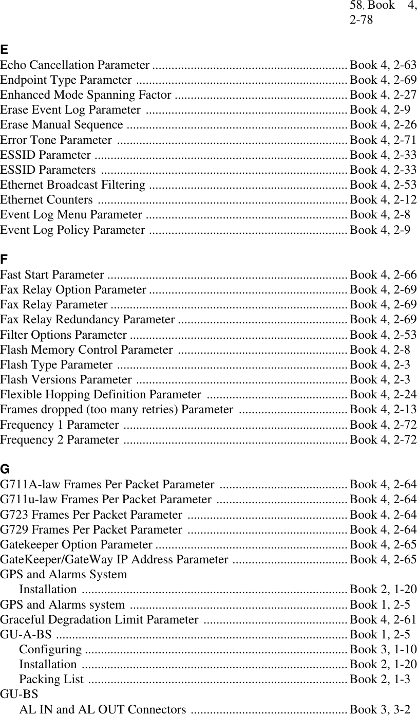
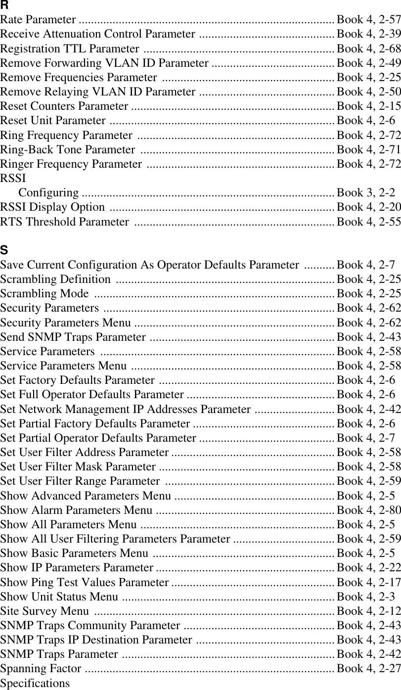
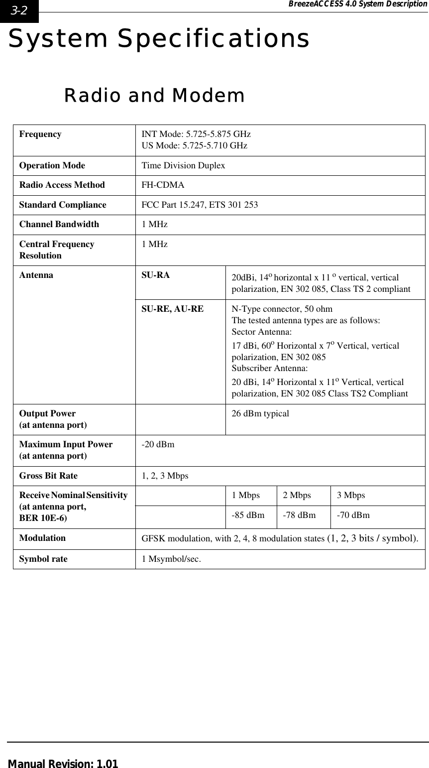
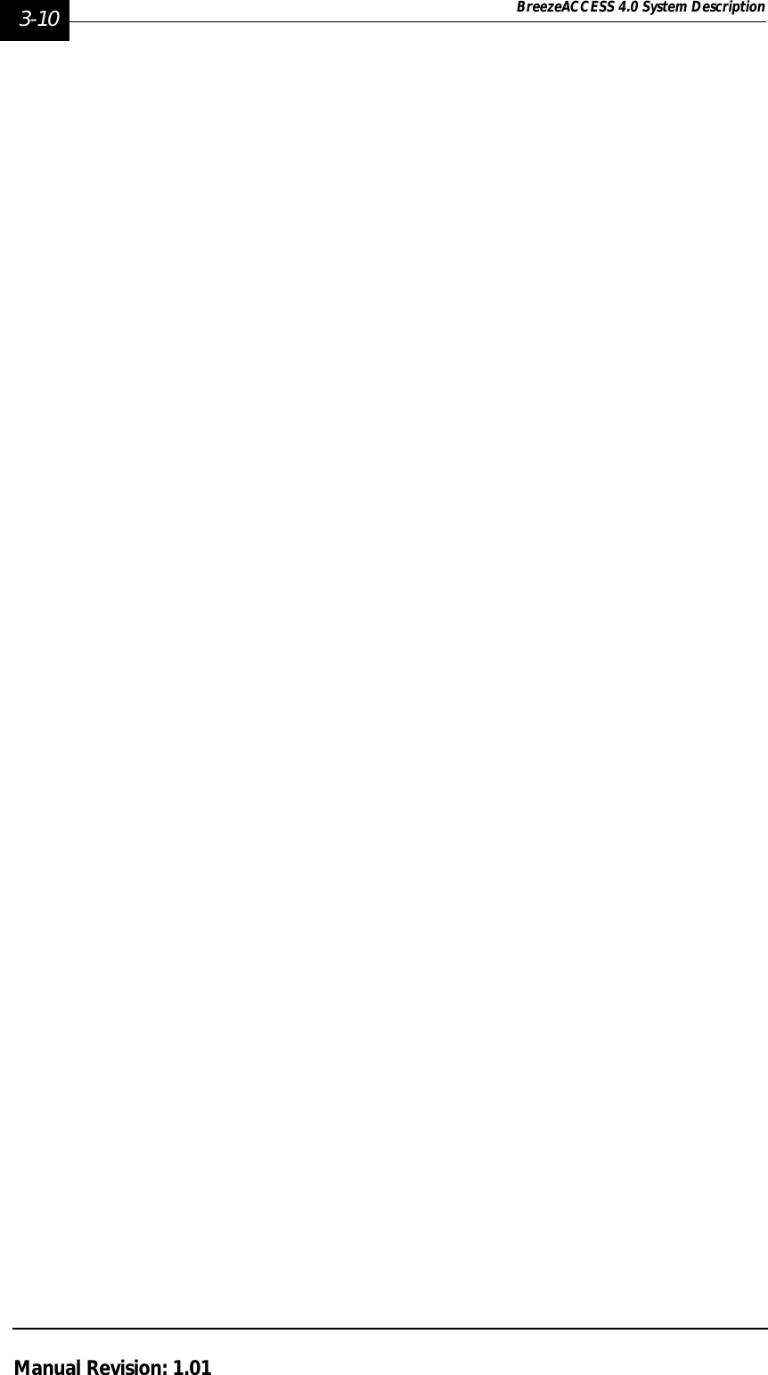
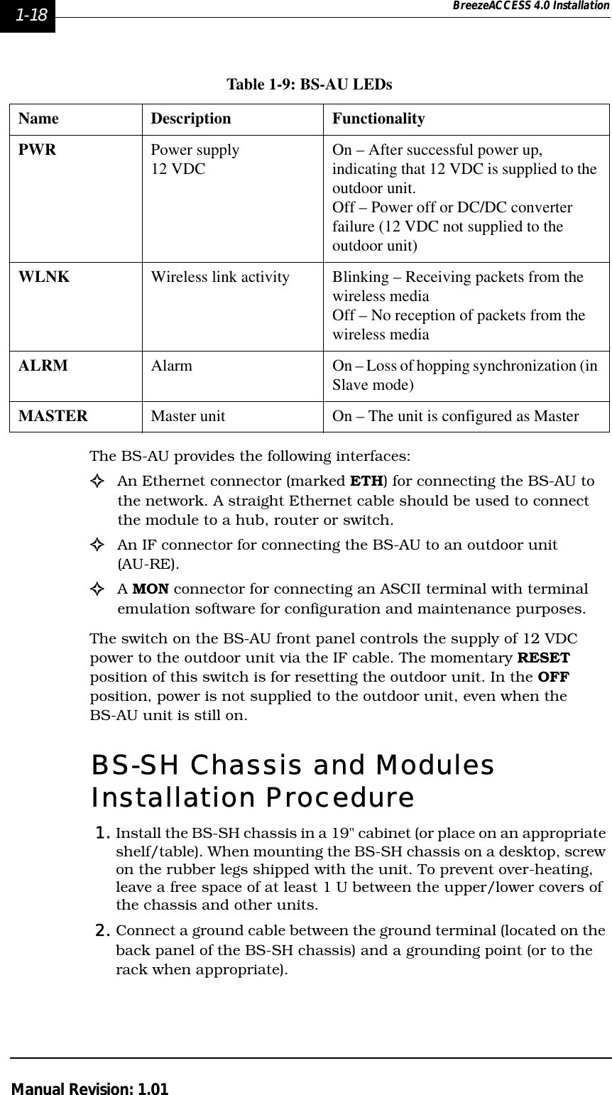
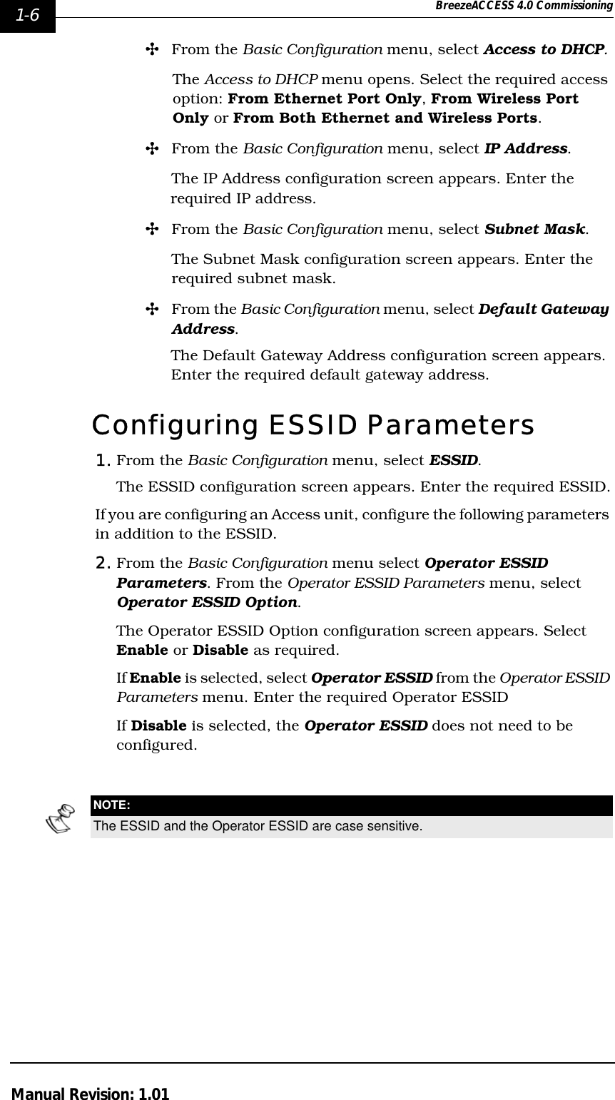
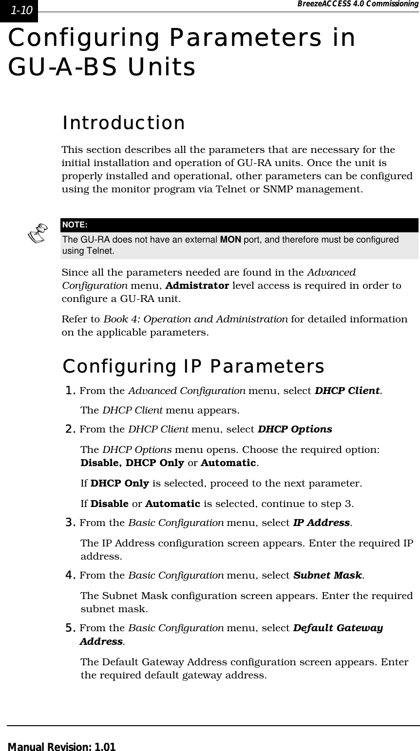
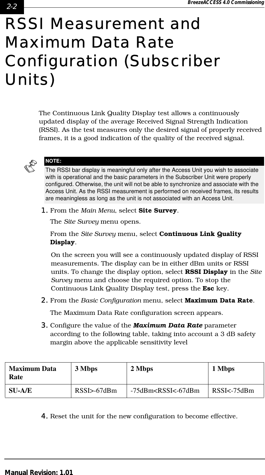
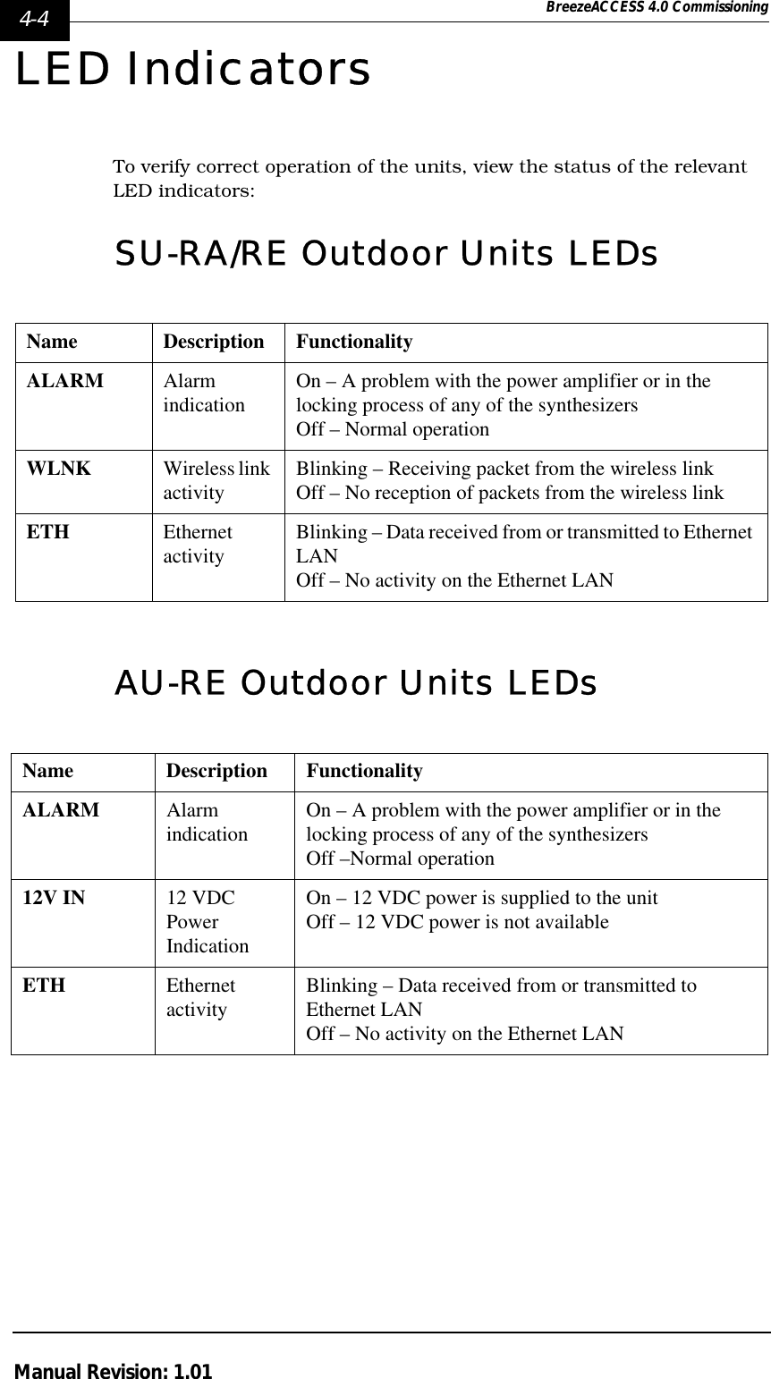
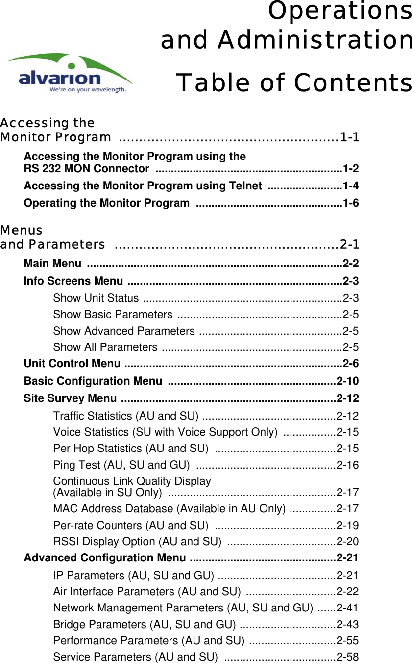
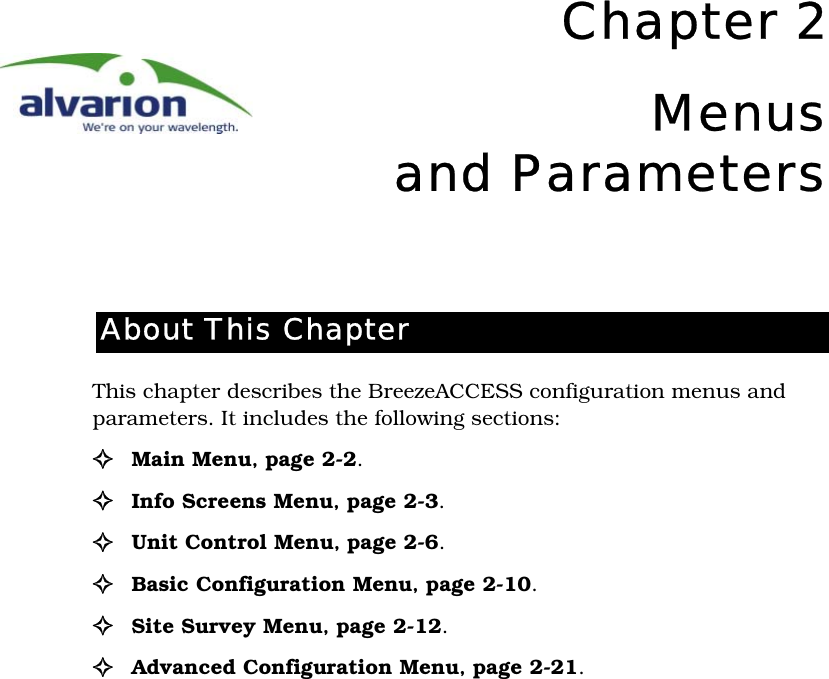
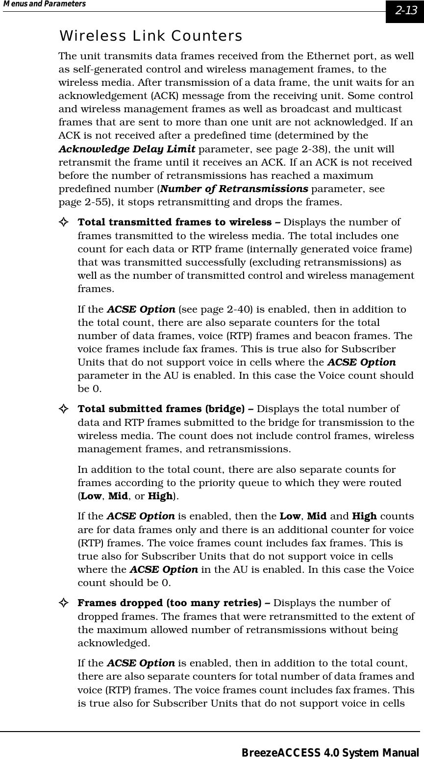
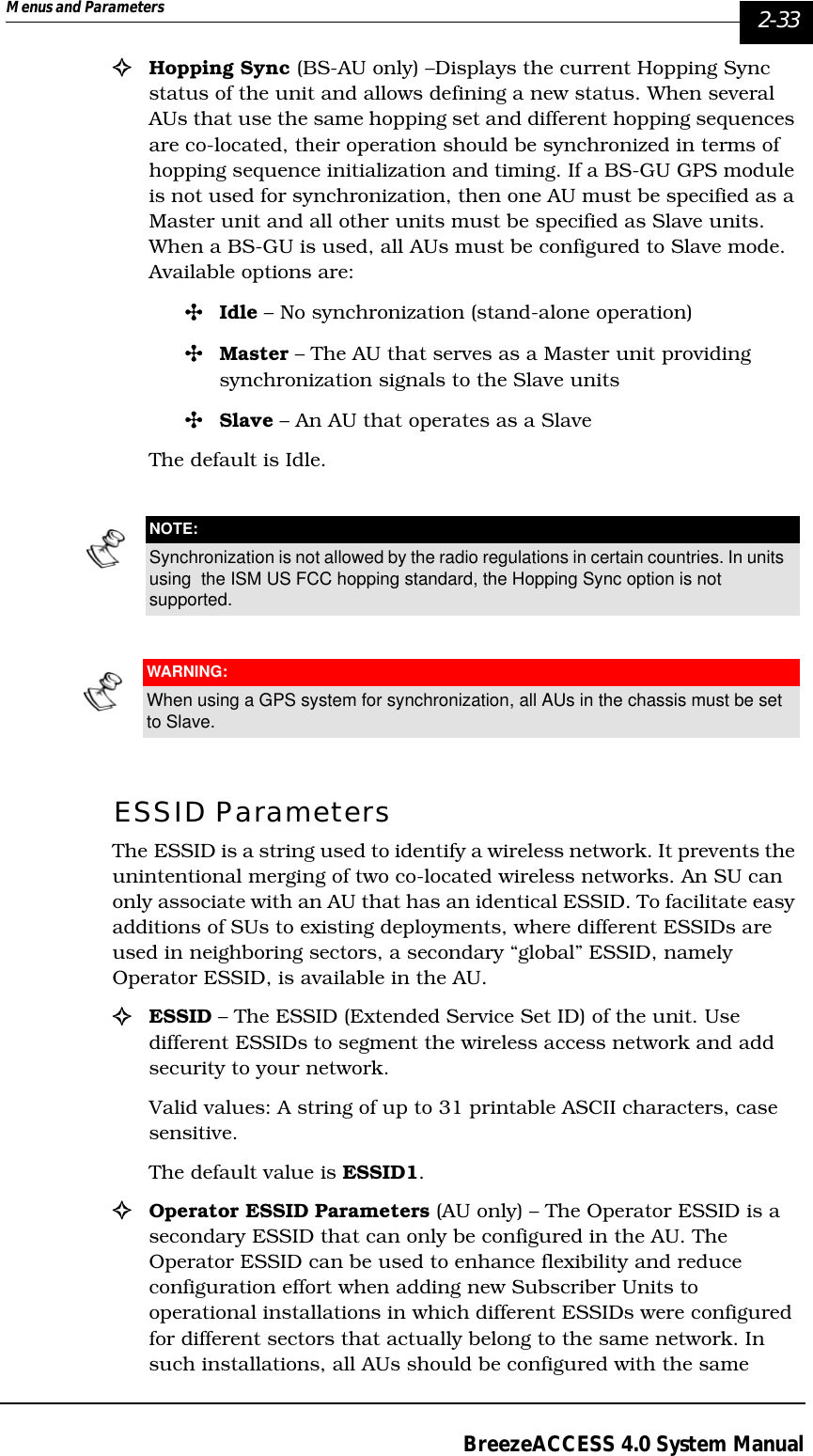
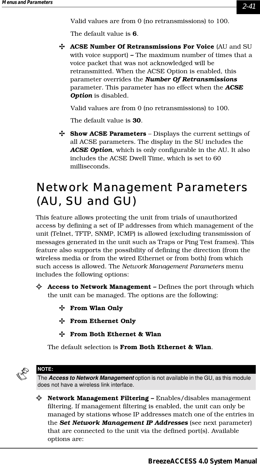
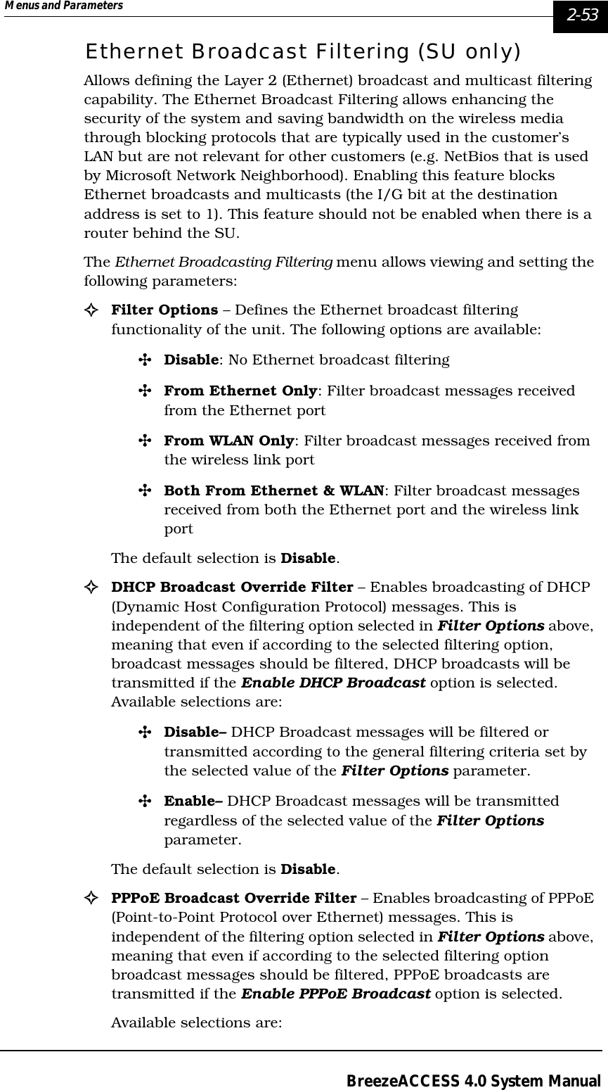
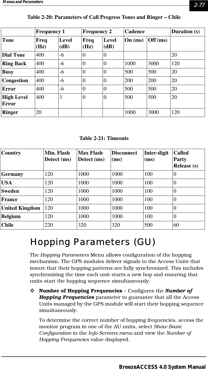
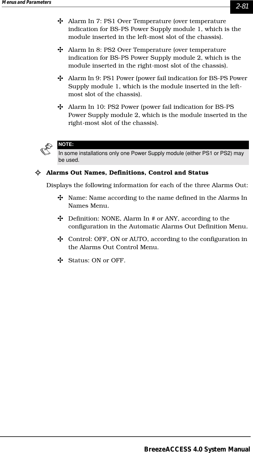
![2-32 BreezeACCESS 4.0 Operations and AdministrationManual Revision: 1.01Table 2-7: Actual Hopping sequences, Standard Scrambling (N=6)The following formula can be used to calculate the actual hopping sequence:P S(i)=P0[(i+s-1)mod(N)+1]Where:S is the hopping shiftN=number of channels in the sequence (modulus)P S(i) is element number i in the actual sequence with hopping shift sP0(i) is element number in the basic hopping sequence (s=0).For example, in the basic sequence sequence with N=6:P0(1) =1P0 (2)=3P0 (3)=5P0 (4)=2P0 (5)=6P0 (6)=4For a shift of 3, the actual sequence is:P3(1) =P0 [(1+3-1)mod6+1]=P0(4)=2P3(2) =P0 [(2+3-1)mod6+1]=P0(5)=6P3(3) =P0 [(3+3-1)mod6+1]=P0(6)=4P3(4) =P0 [(4+3-1)mod6+1]=P0(1)=1P3(5) =P0 [(5+3-1)mod6+1]=P0(2)=3P3(6) =P0 [(6+3-1)mod6+1]=P0(3)=5And the actual hopping sequence is 2, 6, 4, 1, 3, 5.The allowed range for the Hopping shift parameter is from 0 to N-1, where N is the number of hopping frequencies. The default is 0.Hopping shift Hop#1 Hop#2 Hop#3 Hop#4 Hop#5 Hop#605730 5750 5770 5740 5780 576015750 5770 5740 5780 5760 573025770 5740 5780 5760 5730 575035740 5780 5760 5730 5750 577045780 5760 5730 5750 5770 574055760 5730 5750 5770 5740 5780](https://usermanual.wiki/Alvarion-Technologies/IF-57/User-Guide-255470-Page-138.png)
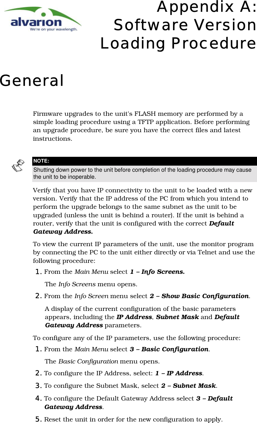
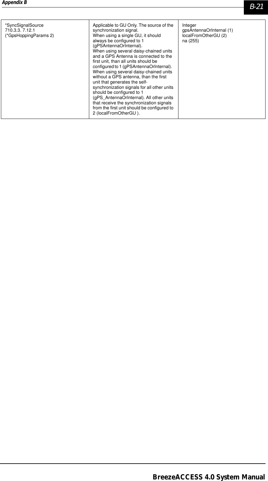
![A-2 BreezeACCESS 4.0 System ManualManual Revision: 1.016. To verify the connection, ping the unit’s IP address. Verify that ping replies are being received.The procedure to be used depends on the unit’s FLASH memory type. Identify the FLASH memory type by using the monitor program, connecting the PC to the unit either directly or via Telnet.From the Main Menu, select 1 – Info Screens. From the Info Screen menu select 1 – Show Unit Status. The last line of the Unit Status display will indicate the FLASH type (type F or type S).Use the TFTP utility, with the following syntax, to perform the upgrade:tftp –i hostaddress put sourcefile [destinationfile]Where -i is for binary mode, hostaddress is the IP address of the unit to be upgraded, put defines that the PC (client) will send a file to the hostaddress and destinationfile is the name of the file to be loaded.](https://usermanual.wiki/Alvarion-Technologies/IF-57/User-Guide-255470-Page-194.png)
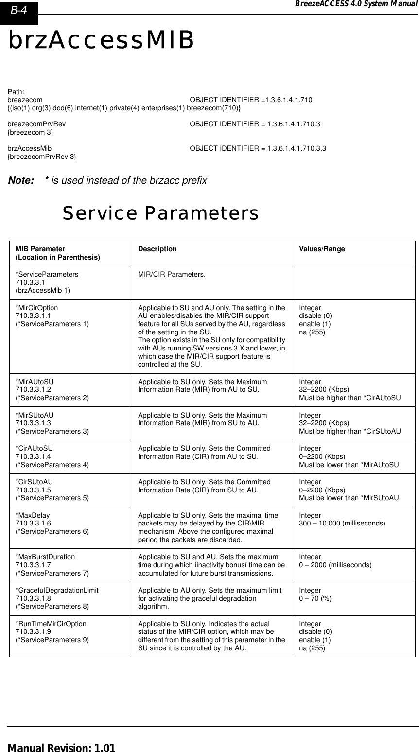
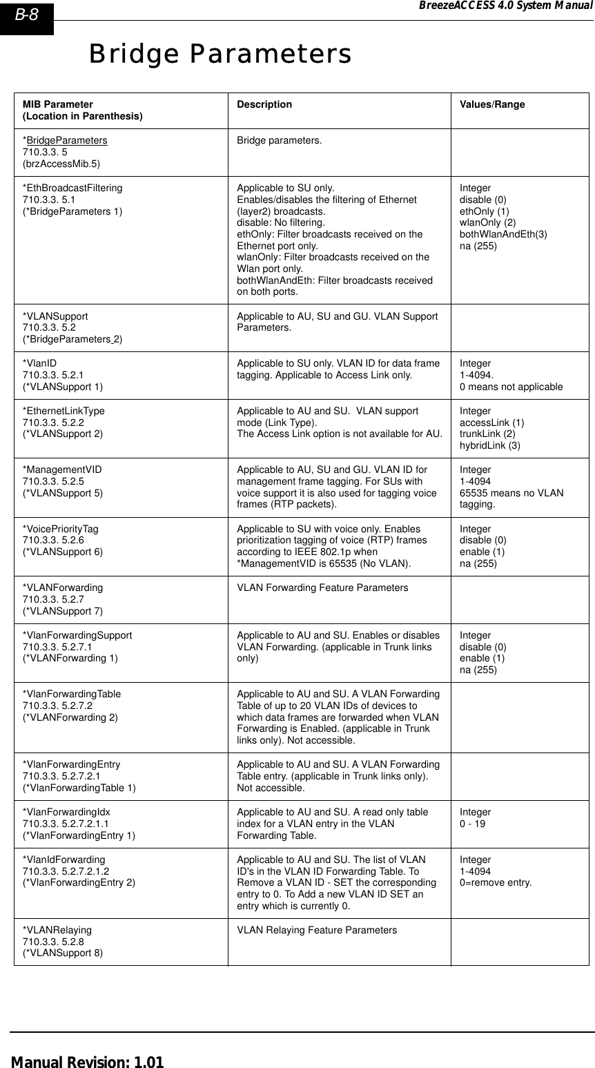
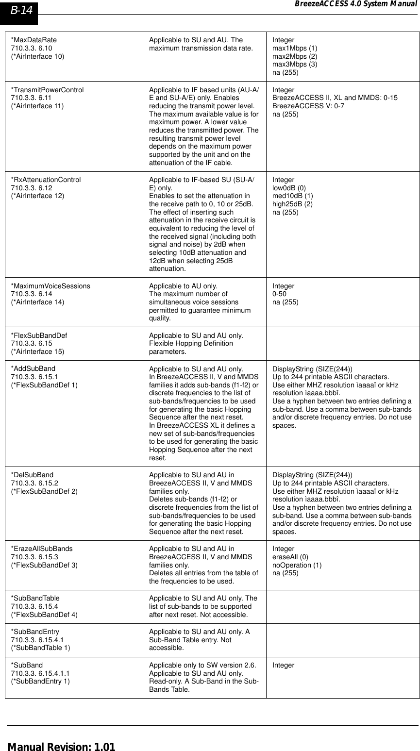
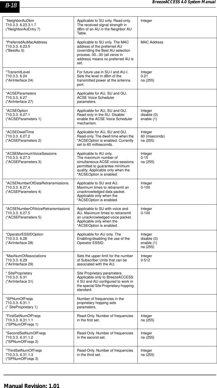
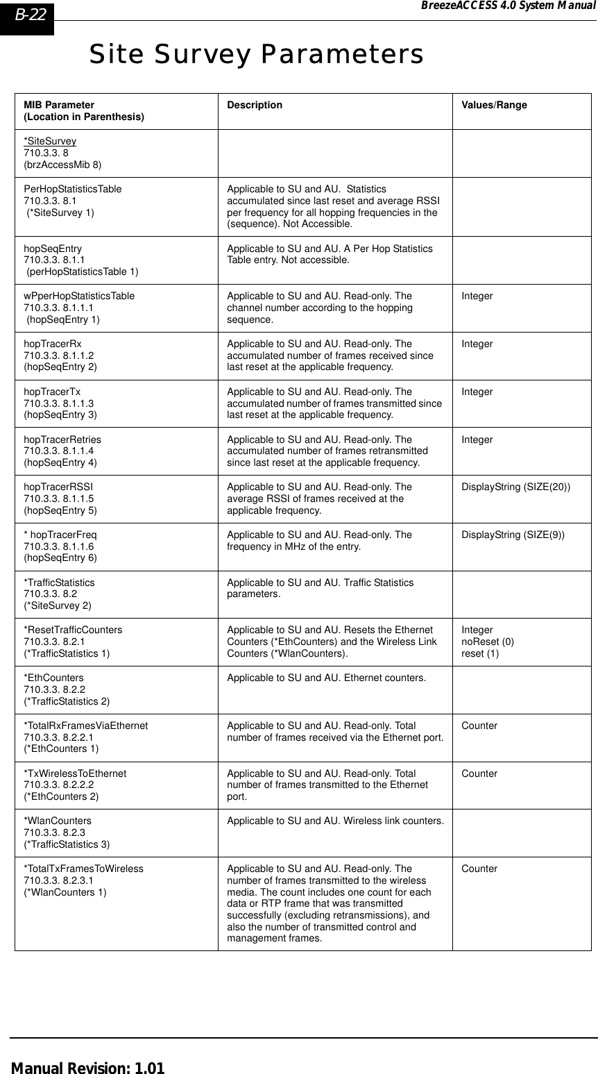
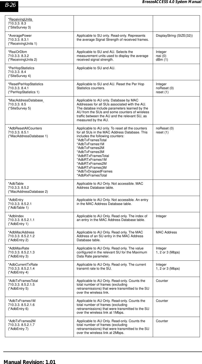
![Appendix B B-11BreezeACCESS 4.0 System ManualAir Interface Parameters MIB Parameter(Location in Parenthesis) Description Values/Range*AirInterface710.3.3. 6 (brzAccessMib 6)*ESSID 710.3.3. 6.1 (*AirInterface 1)Applicable to SU and AU. The Extended Service Set ID (ESSID) used to prevent the merging of collocated systems. Accessible only with SNMP Write Community.DisplayString (SIZE(31))Up to 31 printable case sensitive ASCII characters.*AckDelayLimit710.3.3. 6.2 (*AirInterface 2)Applicable to SU and AU. Defines the maximum time the unit waits for an Acknowledgment (ACK) message before retransmission. Defining a higher range causes the unit to wait a longer time for ACKs before retransmission.Low: Up to 10kmMedium: Up to 20kmHigh: Greater than 20km. IntegerLow (0)Medium (1)High (2)na (255)*FreqOffset710.3.3. 6.3 (*AirInterface 3)Applicable to SU and AU in BreezeACCESS XL family. Not applicable to units that support only Flexible Hopping Definition for setting the hopping frequencies (e.g. 3.3a band). Not applicable in Flexible Hopping Definition mode. Determines the beginning of the actual hopping band or single channel frequency relative to the beginning of the radio band. Start of hopping band (channel) = Start of radio band+2 X Frequency OffsetIntegerna (255)The valid range of values is dependent on the bandwidth of the radio and on the selected Hopping Band.Max. Frequency Offset = [Overall radio bandwidth-Hopping Band]/2*TransmitDiversity710.3.3. 6.4 (*AirInterface 4)Applicable to SU-R, SU-I and AU-I units only. Enables the selection of the antenna(s) to be used for transmission.Integeruse2Antennasn (0)antenna1 (1)antenna2 (2)na (255) *HoppingSequence710.3.3. 6.5 (*AirInterface 5)Applicable to AU in BreezeACCESS II family only.Determines the hopping sequence to be used. Different AUs in the same geographical area should use different Hopping Sequences from the same Hopping Set. The valid range is dependant on the Country Standard.IntegerNa (255)Australia: 1-20Canada: 1-10Europe ETSI: 1-26France: 1-11Israel: 1-11Japan: 1-4Korea: 1-4Netherlands: 1-5Spain: 1-9US FCC: 1-26Mexico: 1-10International: 1-26 *HoppingSet710.3.3. 6.6 (*AirInterface 6)Applicable to AU in BreezeACCESS II family only.Determines the hopping set to be used. All AUs in the same geographical area should use the same Hopping Set.Integer1-3na (255)](https://usermanual.wiki/Alvarion-Technologies/IF-57/User-Guide-255470-Page-209.png)
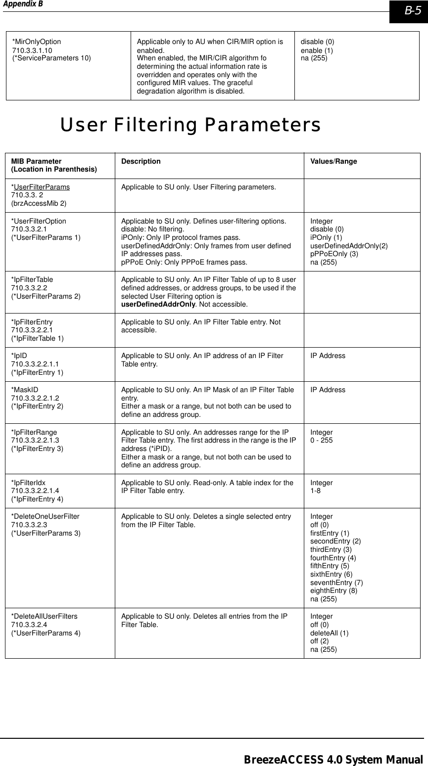
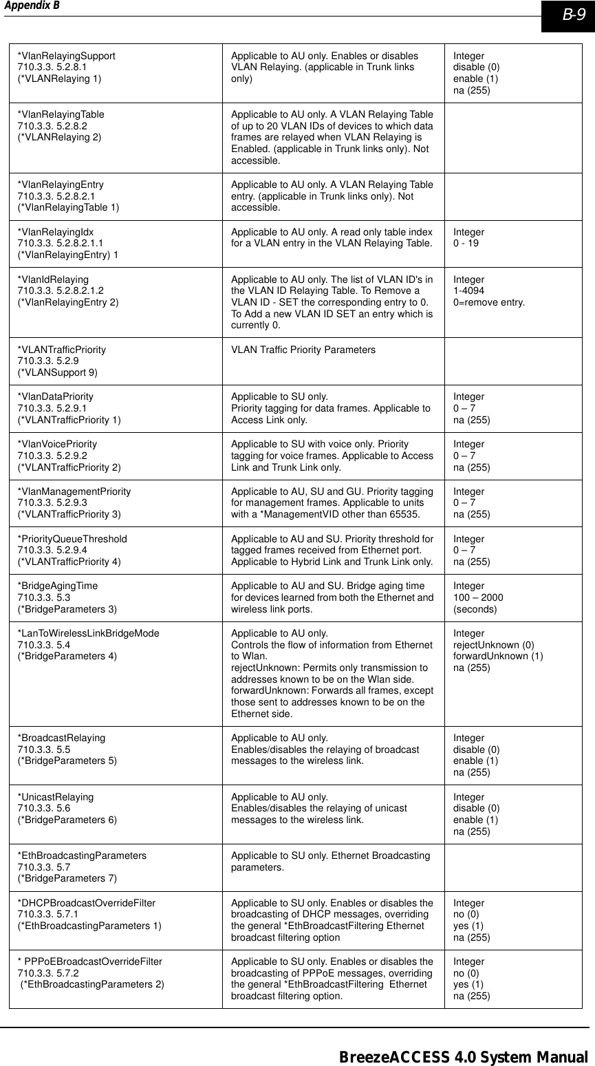
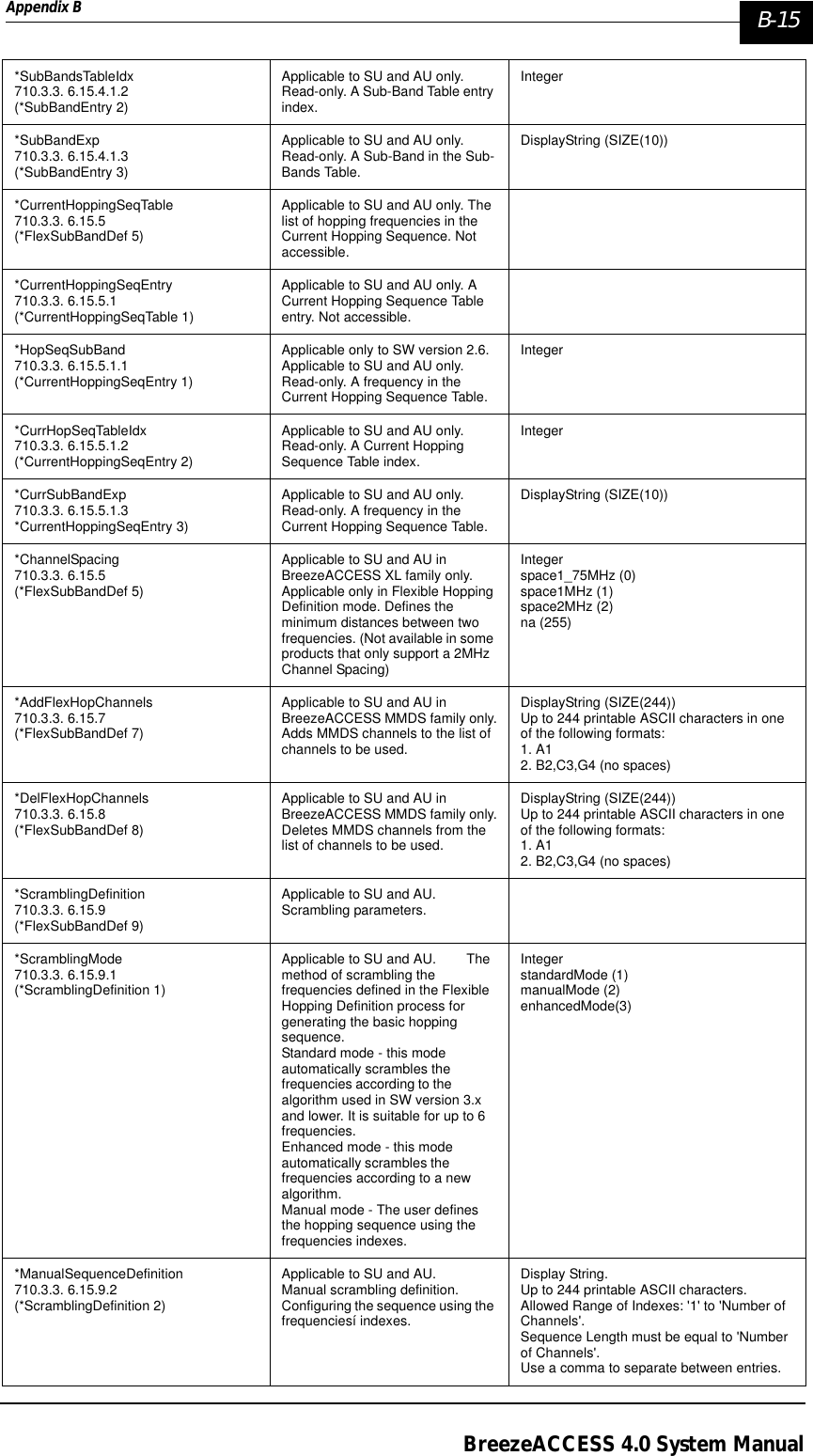
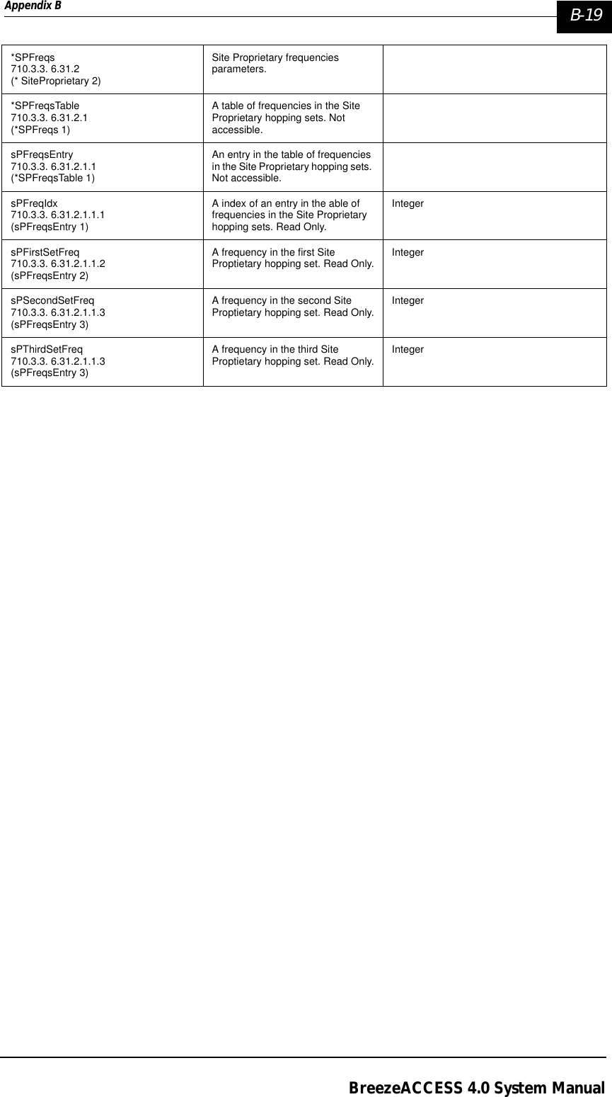
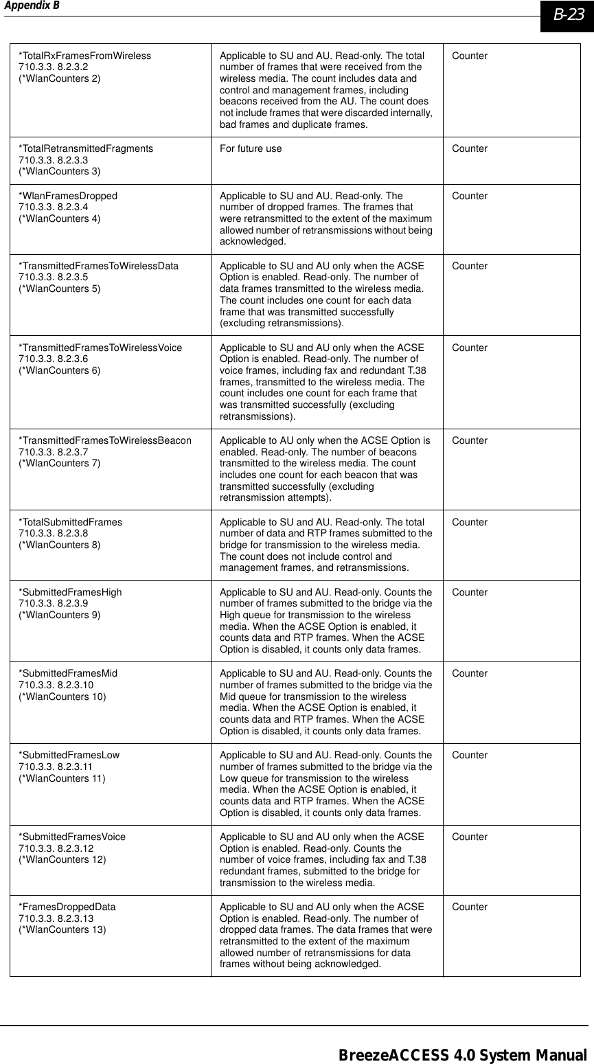
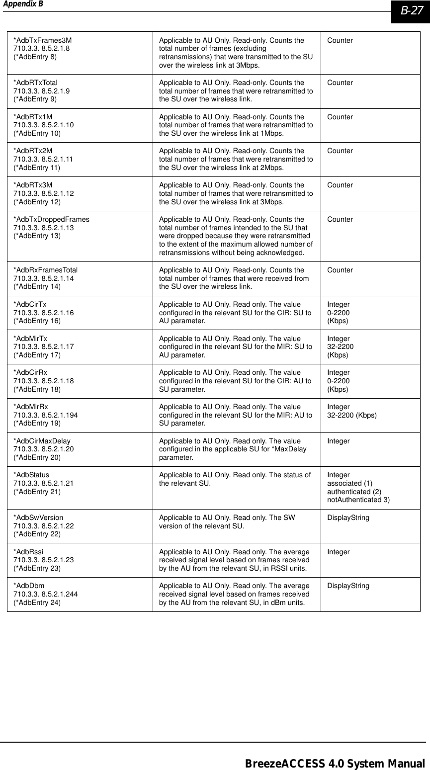
![B-12 BreezeACCESS 4.0 System ManualManual Revision: 1.01*HoppingSync710.3.3. 6.7 (*AirInterface 7)Applicable to BS-AU only.Inter-AU hopping sync functionality of the unit. In the BreezeACCESS II family, synchronization among AUs is not available with the following Country Standards: US FCC, Australia, Canada.In the BreezeACCESS V family, synchronization is not available if the selected hopping band is ISM US FCC.Integeridle (0)slave (1)master (2)na (255)*HoppingShift710.3.3. 6.8 (*AirInterface 8)Applicable to AU in BreezeACCESS V, XL and MMDS families and in BreezeACCESS II if *HoppingBands is frqFlexibleHopping.Defines a hopping pattern different from the basic hopping sequence (Hopping Shift=0). Different collocated AUs should use different hopping shifts. Integerna (255)Range 0 to [number of operational channels-1]](https://usermanual.wiki/Alvarion-Technologies/IF-57/User-Guide-255470-Page-210.png)
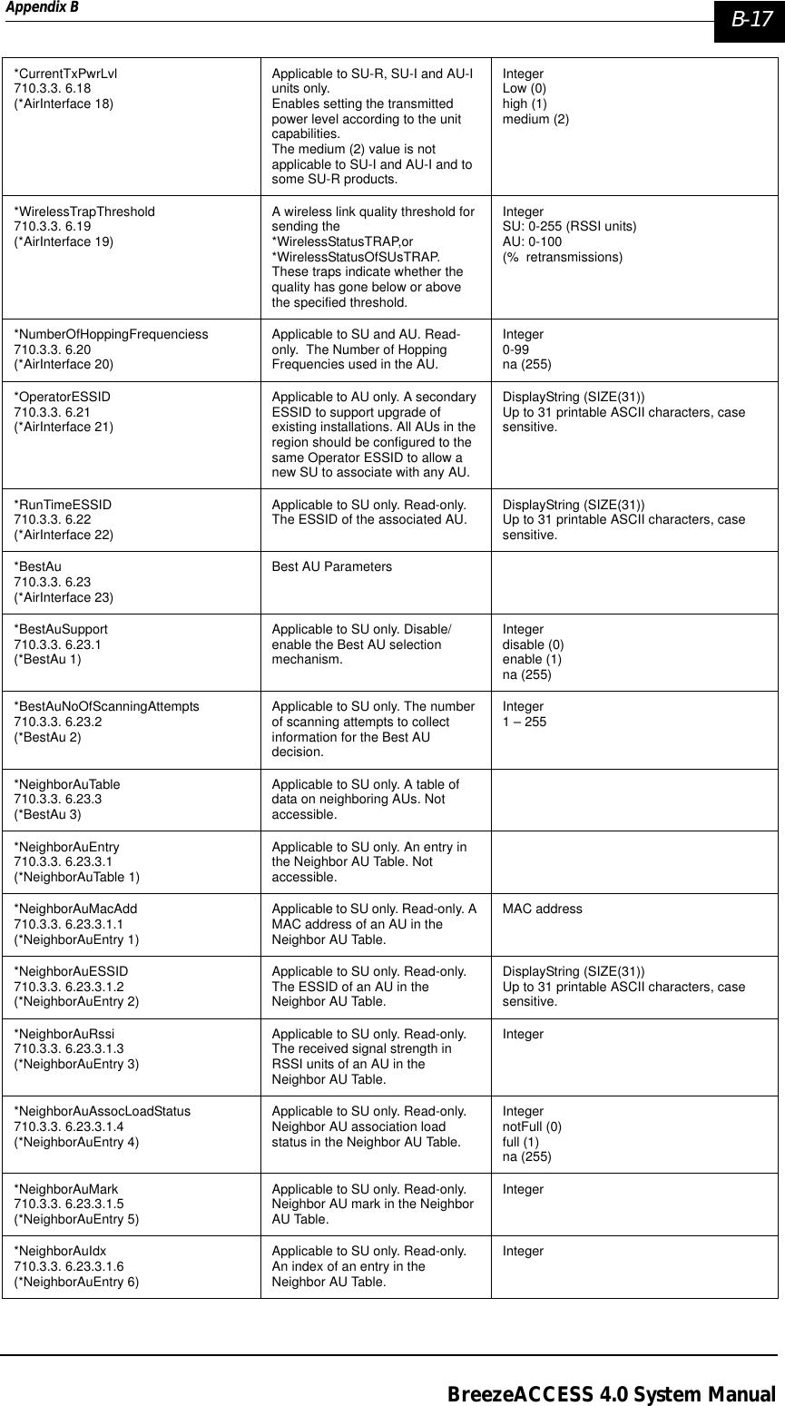
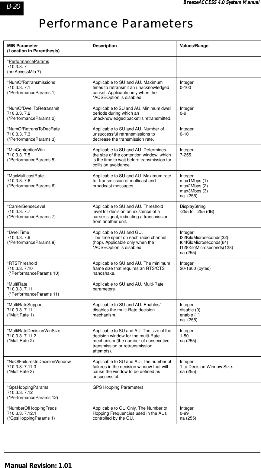
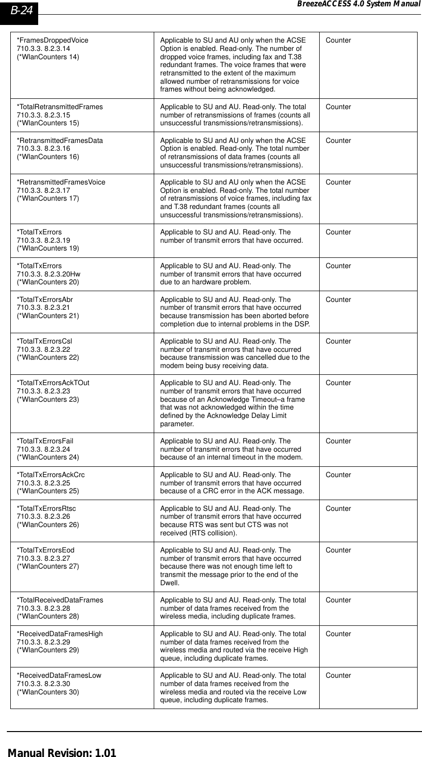
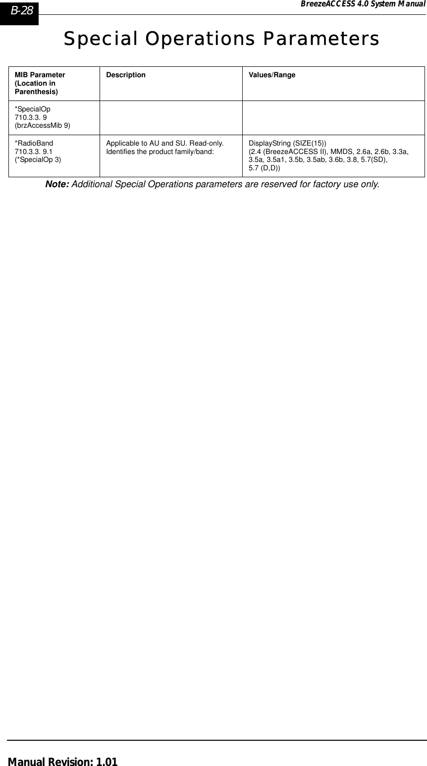
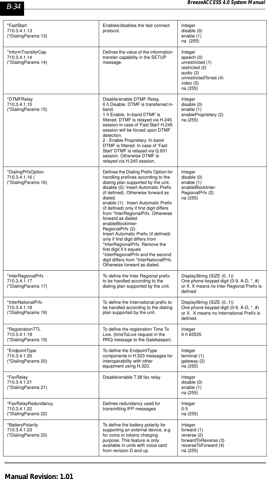
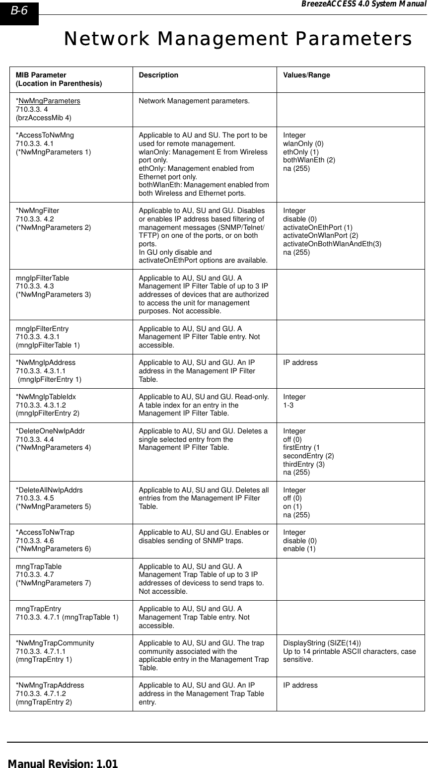
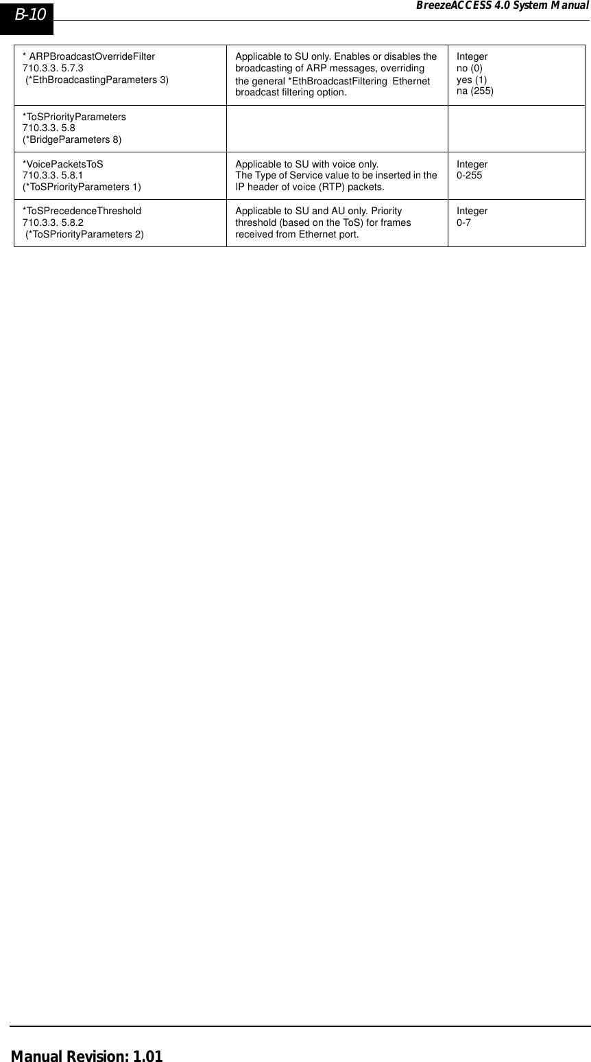
![Appendix B B-33BreezeACCESS 4.0 System ManualbrzPhoneMIB (applicable to SU with voice only)breezecom OBJECT IDENTIFIER =1.3.6.1.4.1.710{(iso(1) org(3) dod(6) internet(1) private(4) enterprises(1) breezecom(710)} breezecomPrvRev OBJECT IDENTIFIER = 1.3.6.1.4.1.710.3{breezecom 3}brzPhoneMib OBJECT IDENTIFIER = 1.3.6.1.4.1.710.3.4{breezecomPrvRev 4 }Note: * is used instead of the phon prefixDialing ParametersMIB Parameter(Location in Parenthesis) Description Values*DialingParams 710.3.4.1(brzPhonMib 1)*PulseDialing710.3.4.1.1 (*DialingParams 1)Enables/disables automatic pulse dialing detection. Integerdisable (0)enable (1)na (255)*GateKeeperOption 710.3.4.1.2 (*DialingParams 2)Enables/disables communicating with the Gatekeeper for call management purposes.Integerdisable (0)enable (1)na (255)*GkGwIpAddress710.3.4.1.3 (*DialingParams 3)IP Address of the Gateway/GatekeeperThe parameters must be specified if the [*GateKeeperOption] is enabled.IP address*MyTelephoneNumber 710.3.4.1.4 (*DialingParams 4)The telephone number as specified in the Gateway, if [*GateKeeperOption] is disabled. If the [*GateKeeperOption] is enabled the number is transmitted to the Gatekeeper.DisplayString (SIZE (0..10))Up to 10 characters.0 means no number*H323TerminalID 710.3.4.1.5 (*DialingParams 5)The H323 Terminal ID (name) to be used for calling the unit if the feature is enabled.Applicable only if the [*GateKeeperOption] is enabled.DisplayString (SIZE (0..25))Up to 24 characters.X=NoID *IpDialingOption 710.3.4.1.8 (*DialingParams 8)Enables/disables dialing using IP addresses. Integerdisable (0)enable (1)na (255)*IpDialingIndicator 710.3.4.1.9 (*DialingParams 9)Specifies the prefix used to identify an IP dialing string. DisplayString (SIZE (0..15))Up to three telephone pad digits (0-9, A-D, *, #). X means no IP Dialing Indicator*AutomaticPrefix710.3.4.1.10(*DialingParams 10)Specifies a default prefix (number of Gateway trunk) to be automatically inserted before the dialed number.DisplayString (SIZE (0..15))Up to eight telephone pad digits (0-9, A-D, *, #).X means no Automatic Prefix.](https://usermanual.wiki/Alvarion-Technologies/IF-57/User-Guide-255470-Page-231.png)