Alvarion Technologies SUR-24 Indoor Subscriber Unit User Manual
Alvarion Ltd. Indoor Subscriber Unit
UserManual.wiki
>
Alvarion Technologies
>
SUR-24 User Manual
>
User Manual
Contents
1.
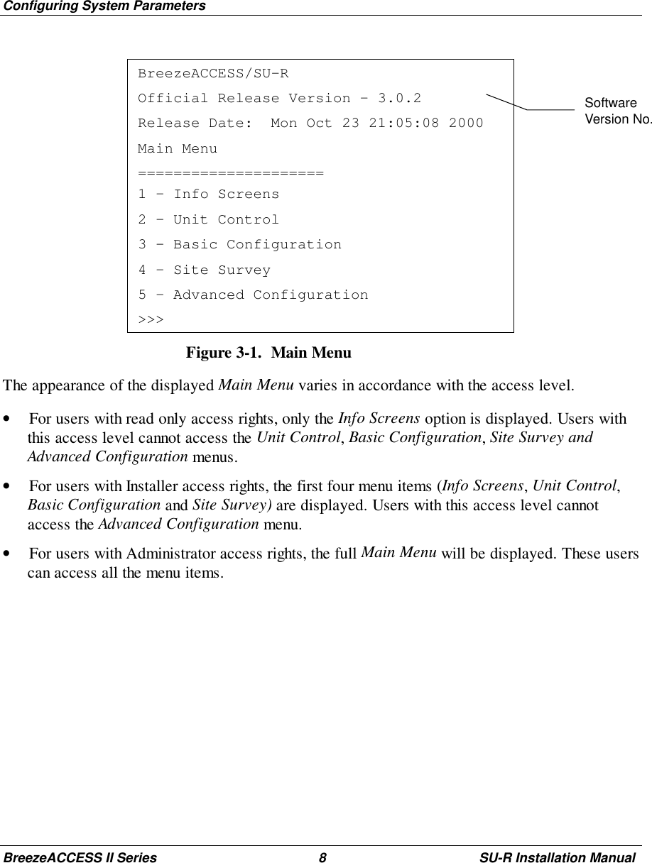
User Manual
2.
Updated user manual per 14 Aug corr
3.
revised user manual re antenna installation in red type
4.
revised user manual with new antenna data
5.
User manual version dated 18 March
6.
user manual
User Manual
Navigation menu
Upload a User Manual
Namespaces
Wiki Guide
HTML
PDF
Info
Views
User Manual
Discussion / Help
Navigation