Alvarion Technologies VL-53 Wireless Bridge User Manual
Alvarion Ltd. Wireless Bridge
UserManual.wiki
>
Alvarion Technologies
>
VL-53 User Manual
>
User Manual
Contents
1.
User Manual
2.
User Manual 1
3.
User Manual 2
4.
User Manual 3
User Manual
Navigation menu
Upload a User Manual
Namespaces
Wiki Guide
HTML
PDF
Info
Views
User Manual
Discussion / Help
Navigation
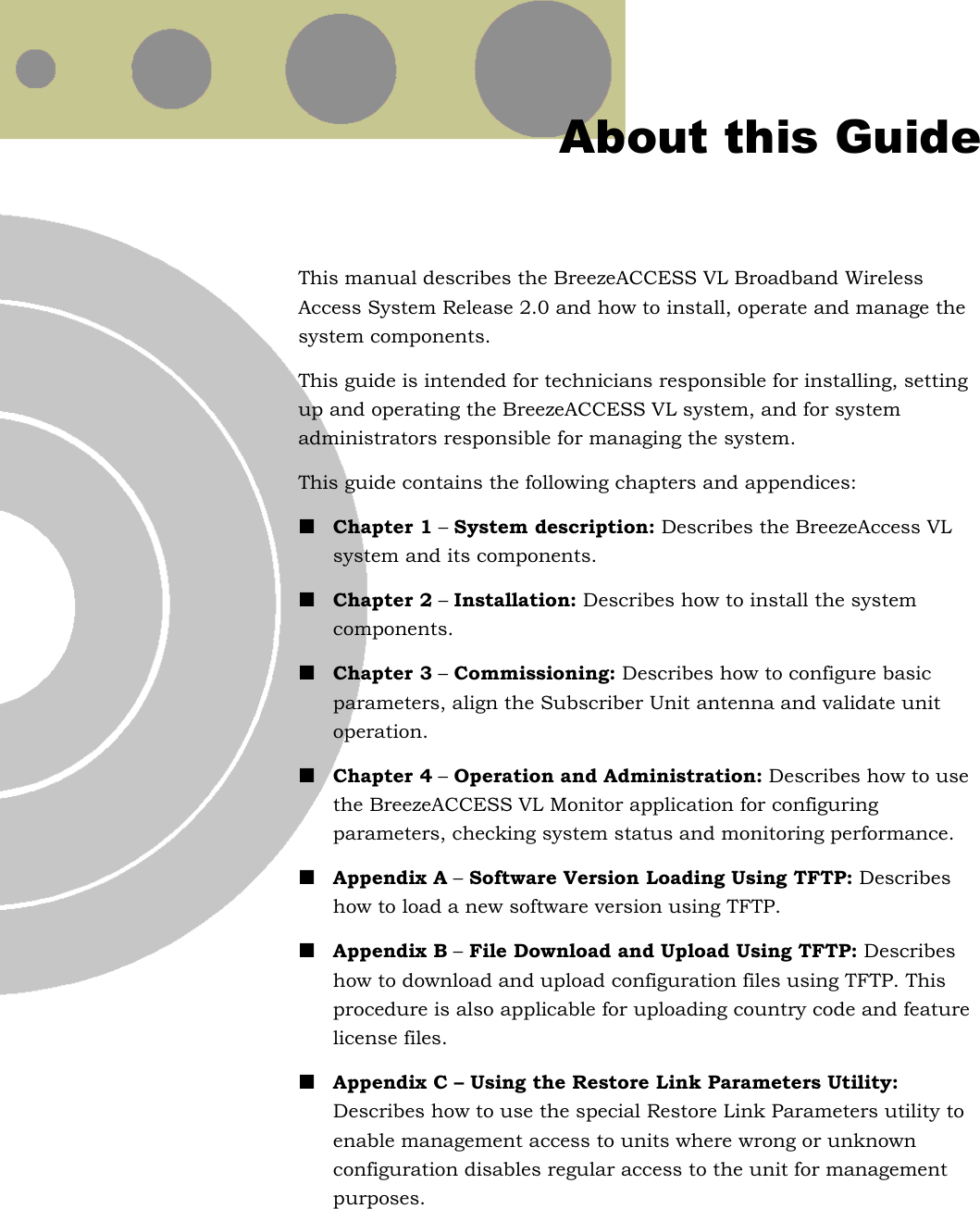
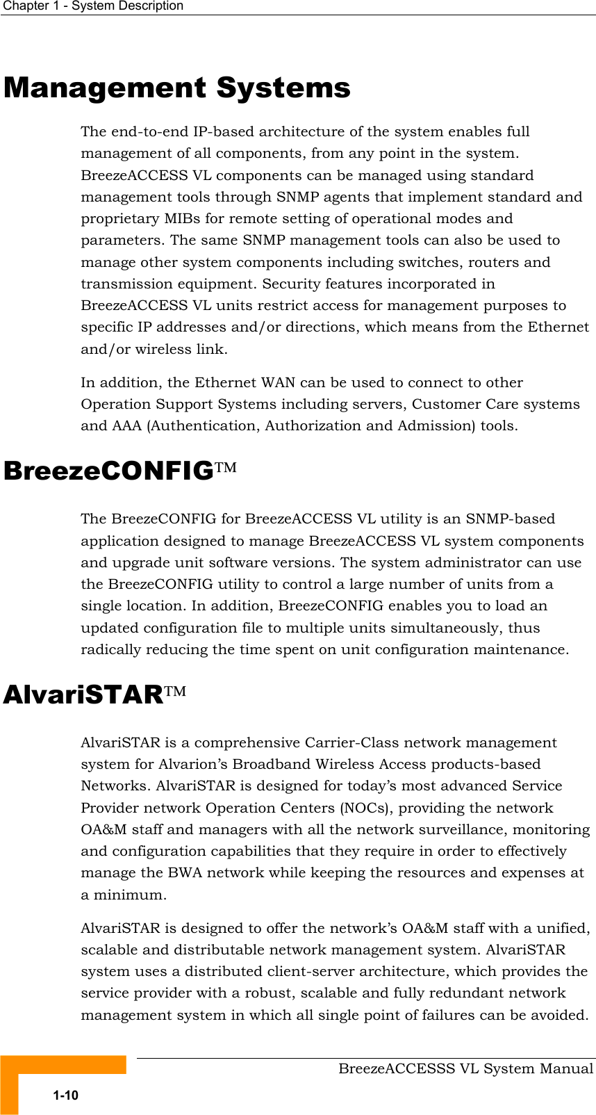
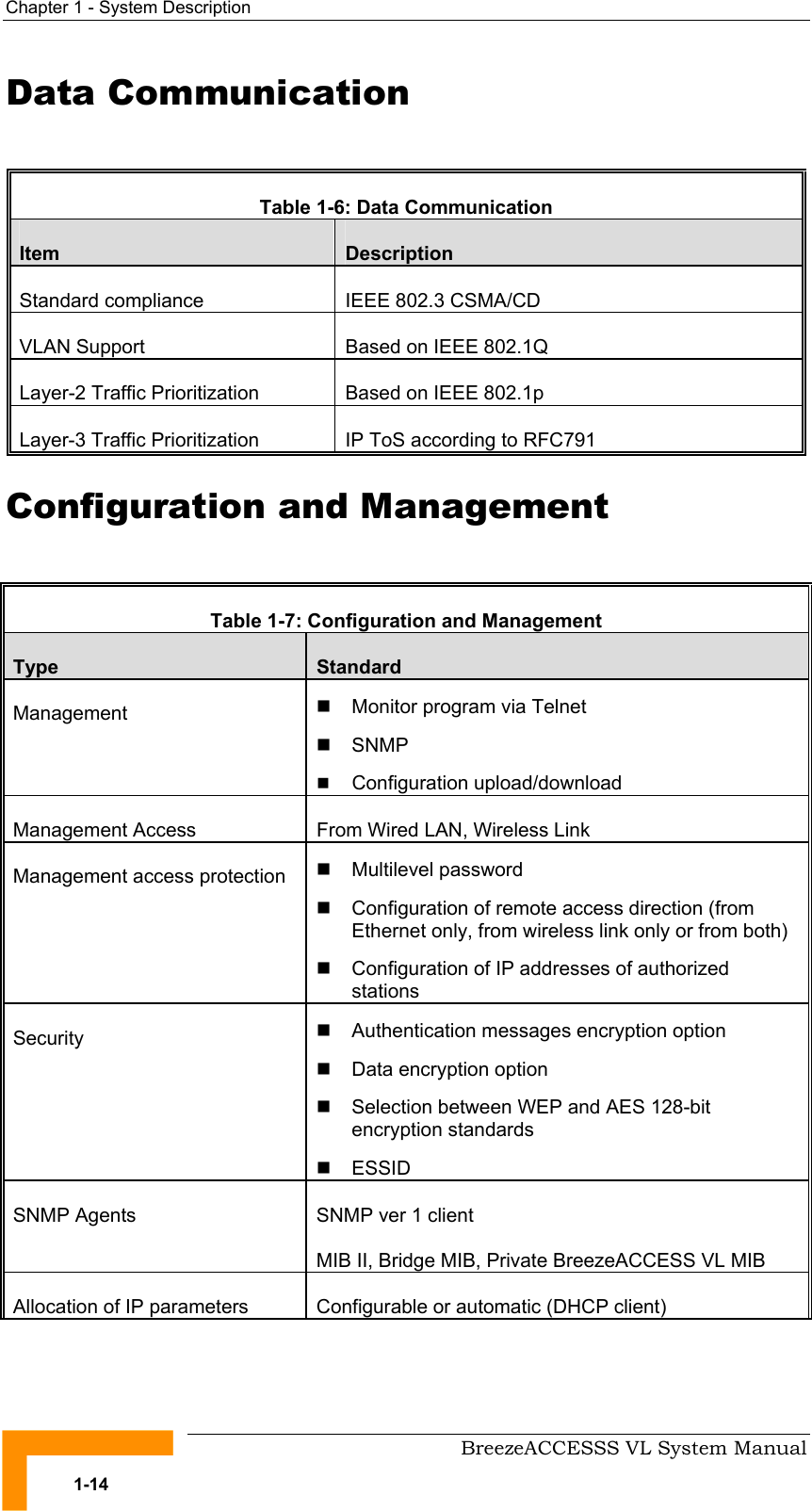
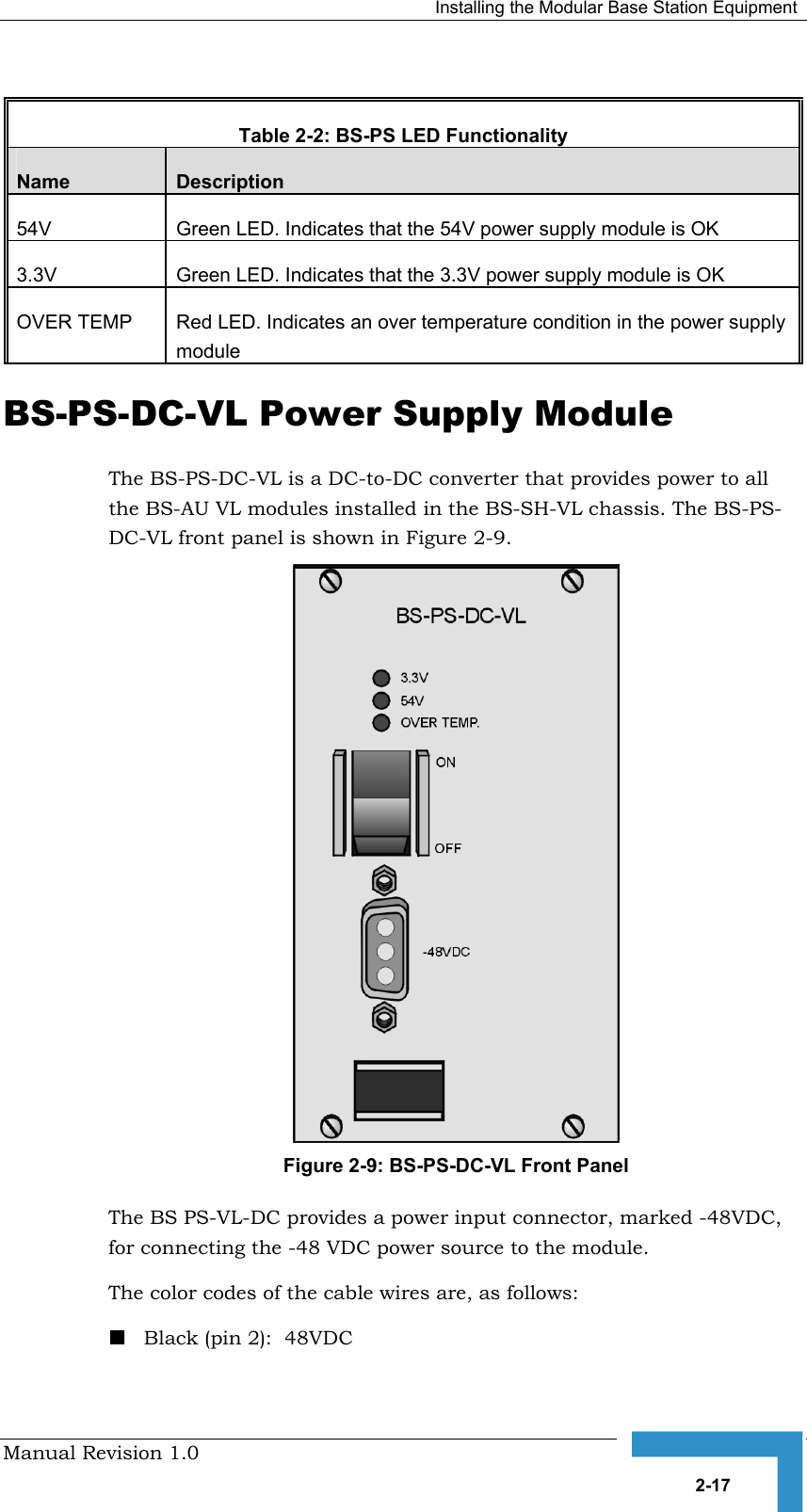
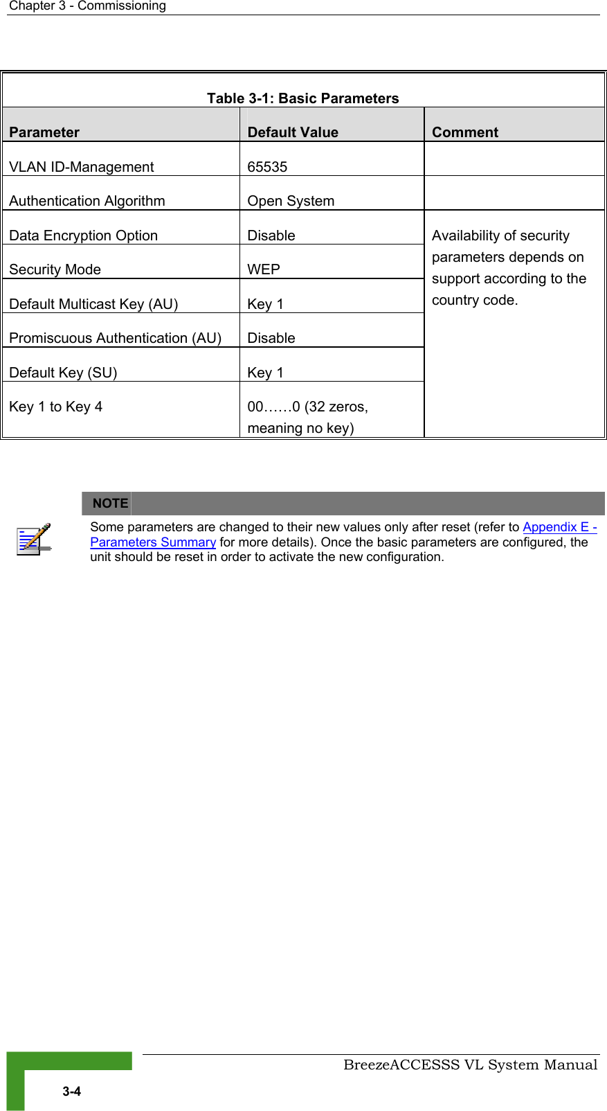
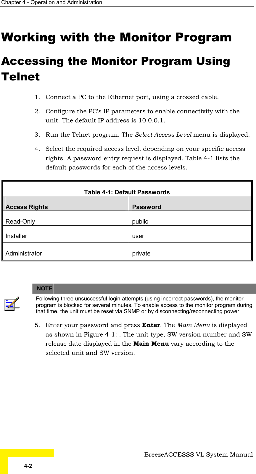
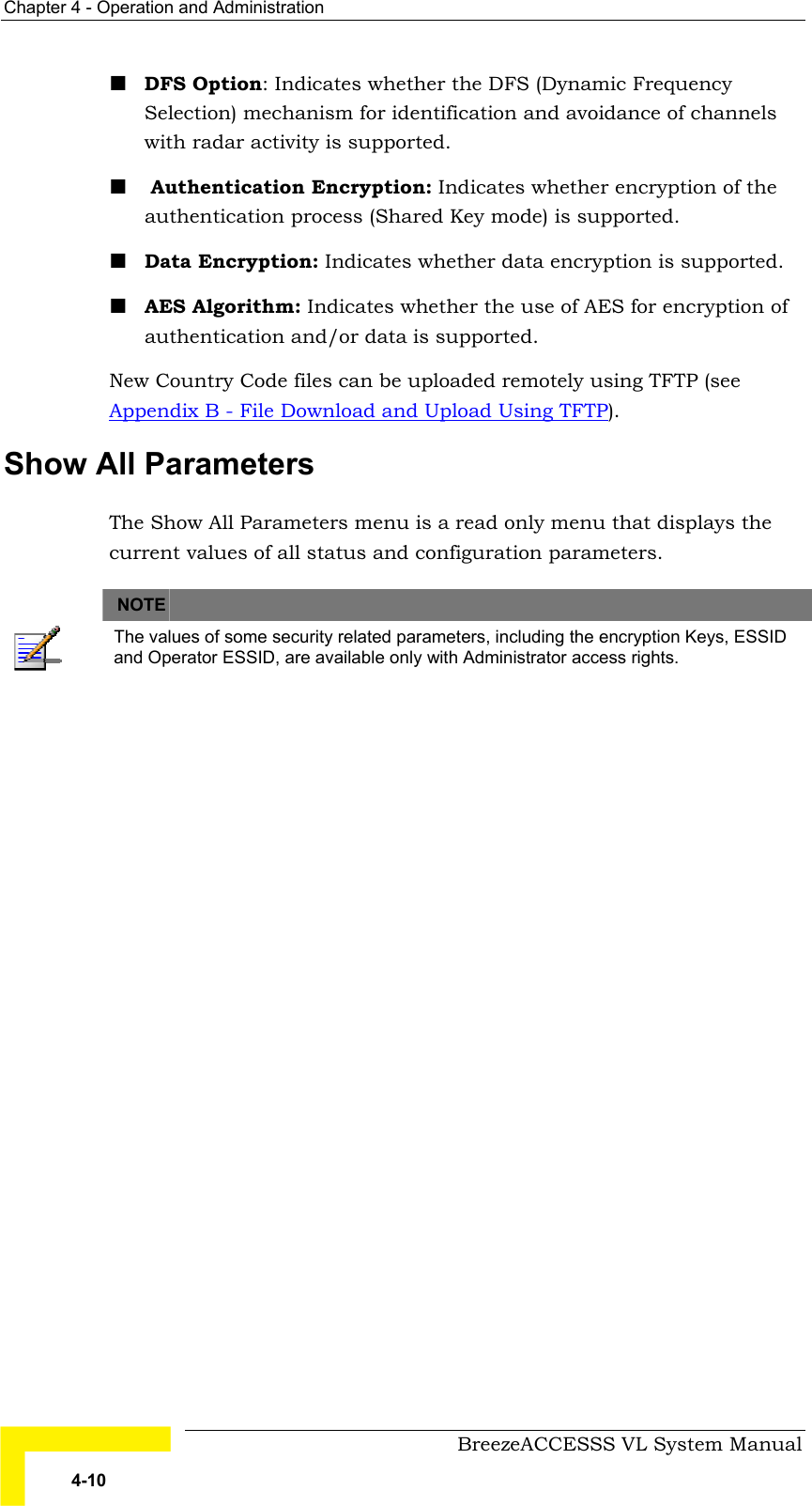
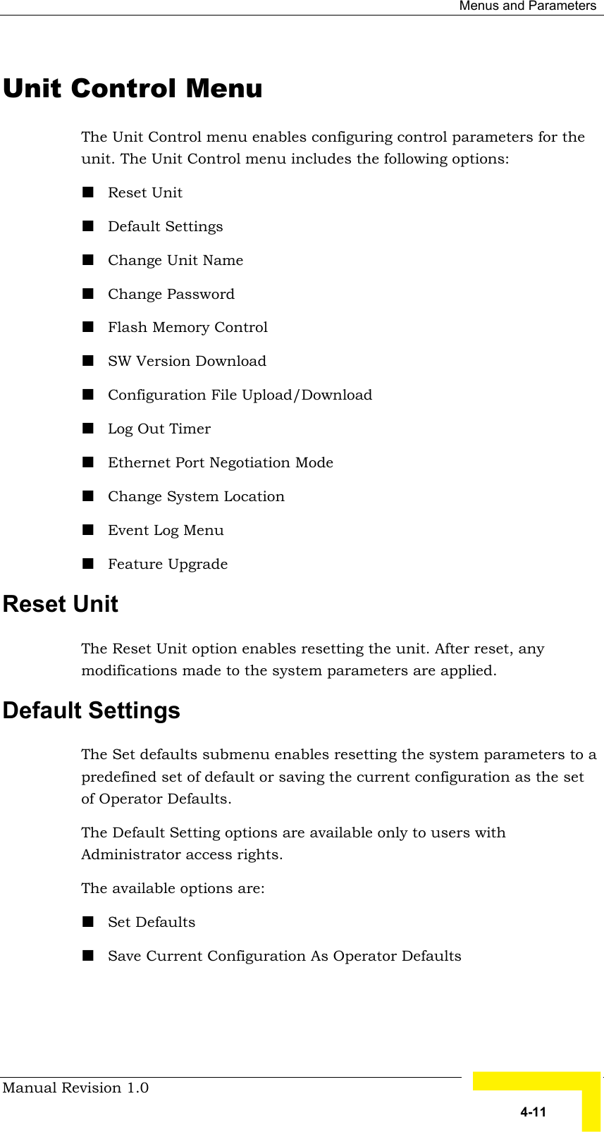
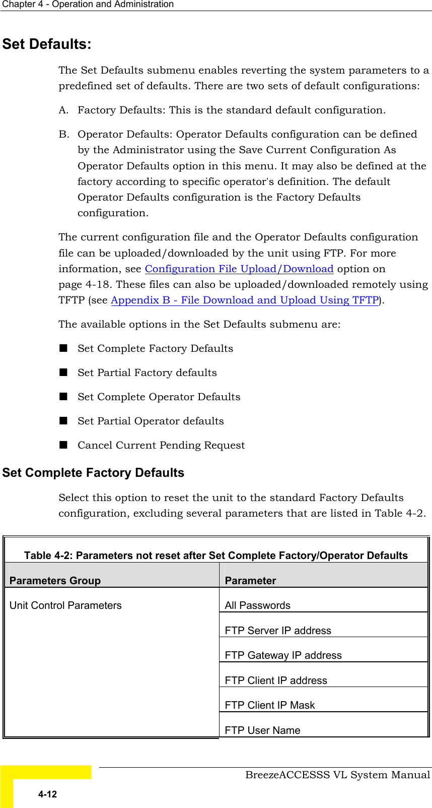
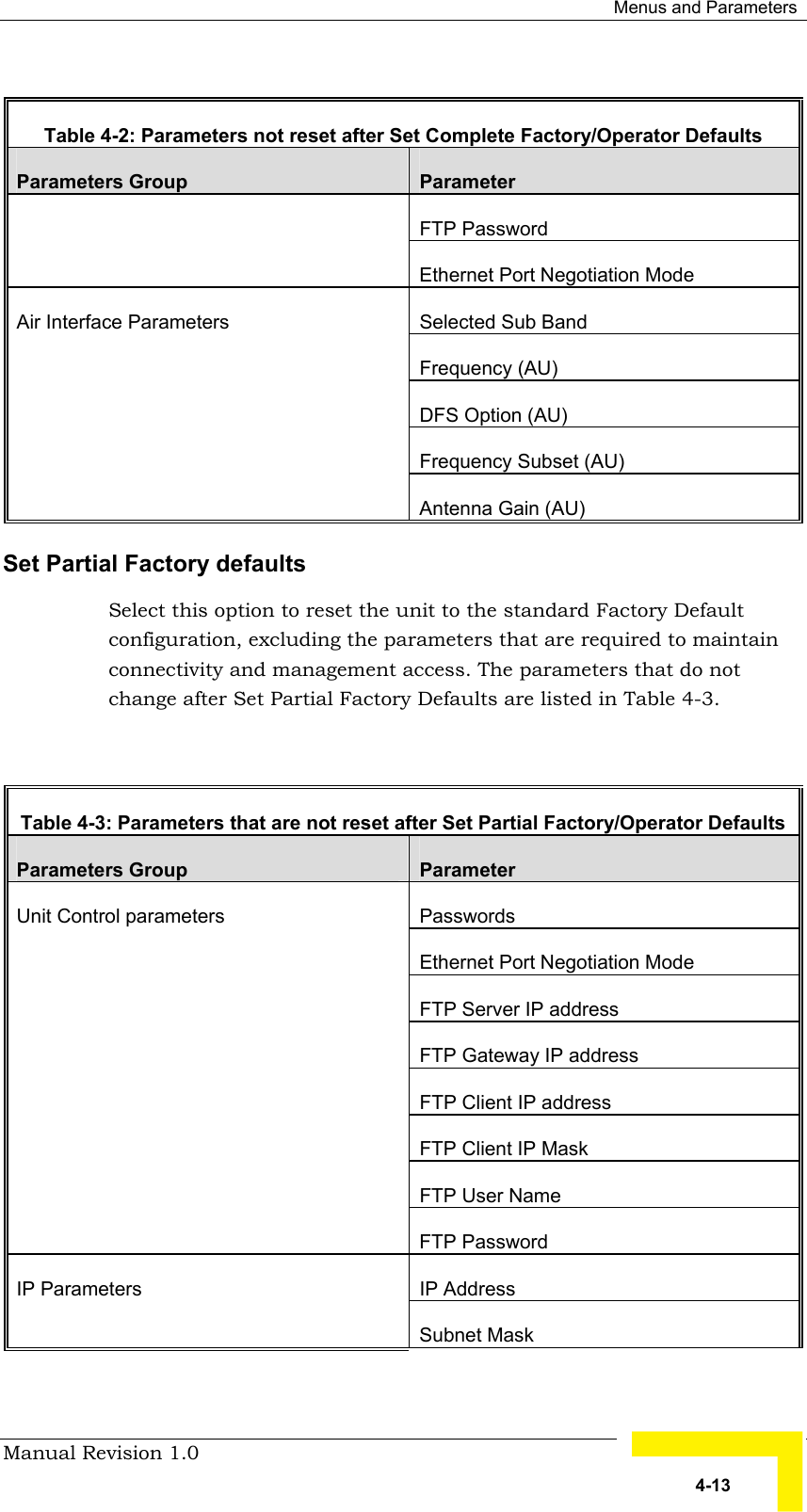
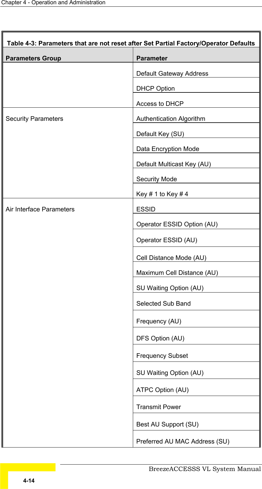
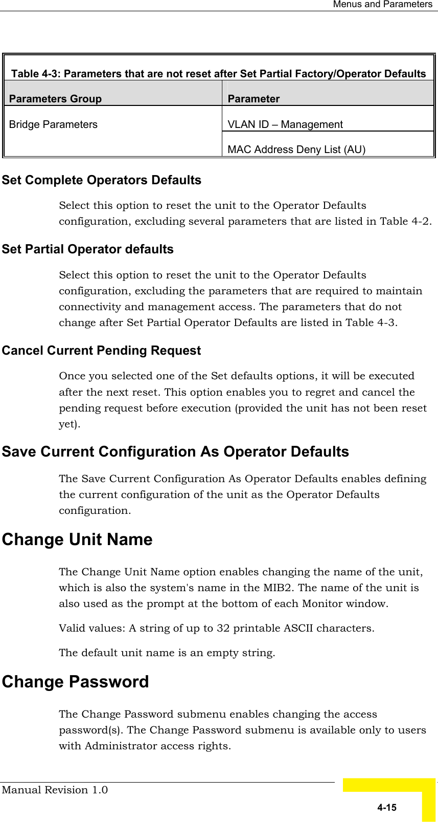
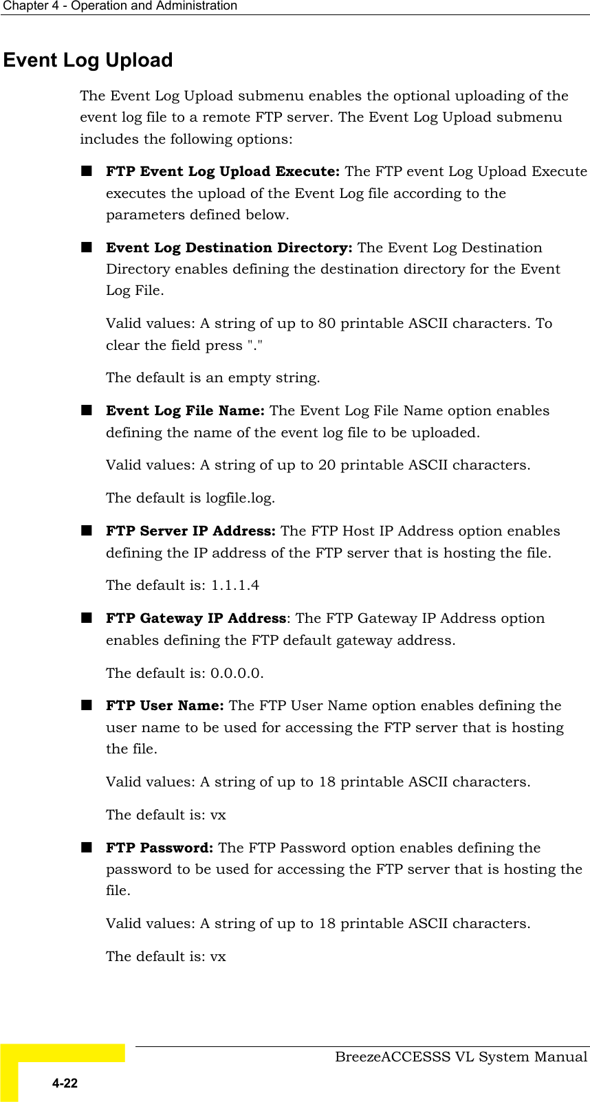
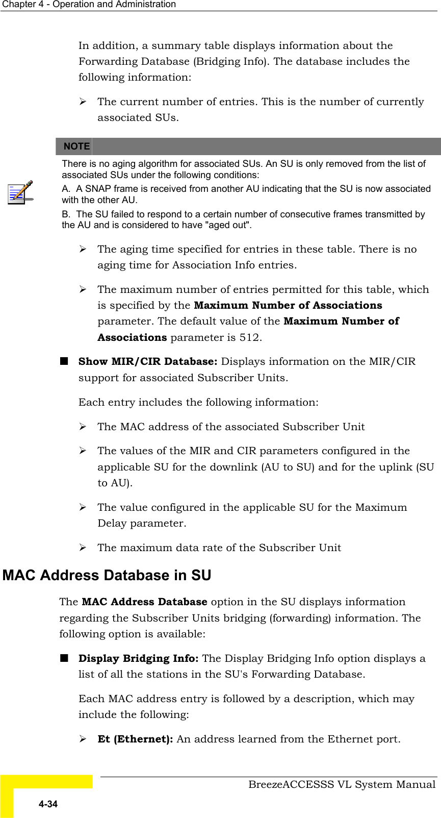
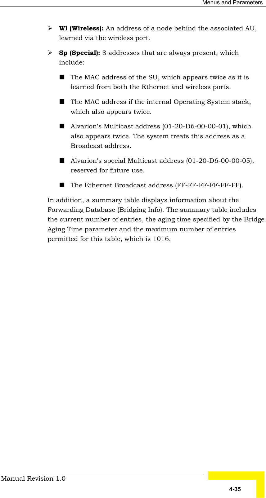
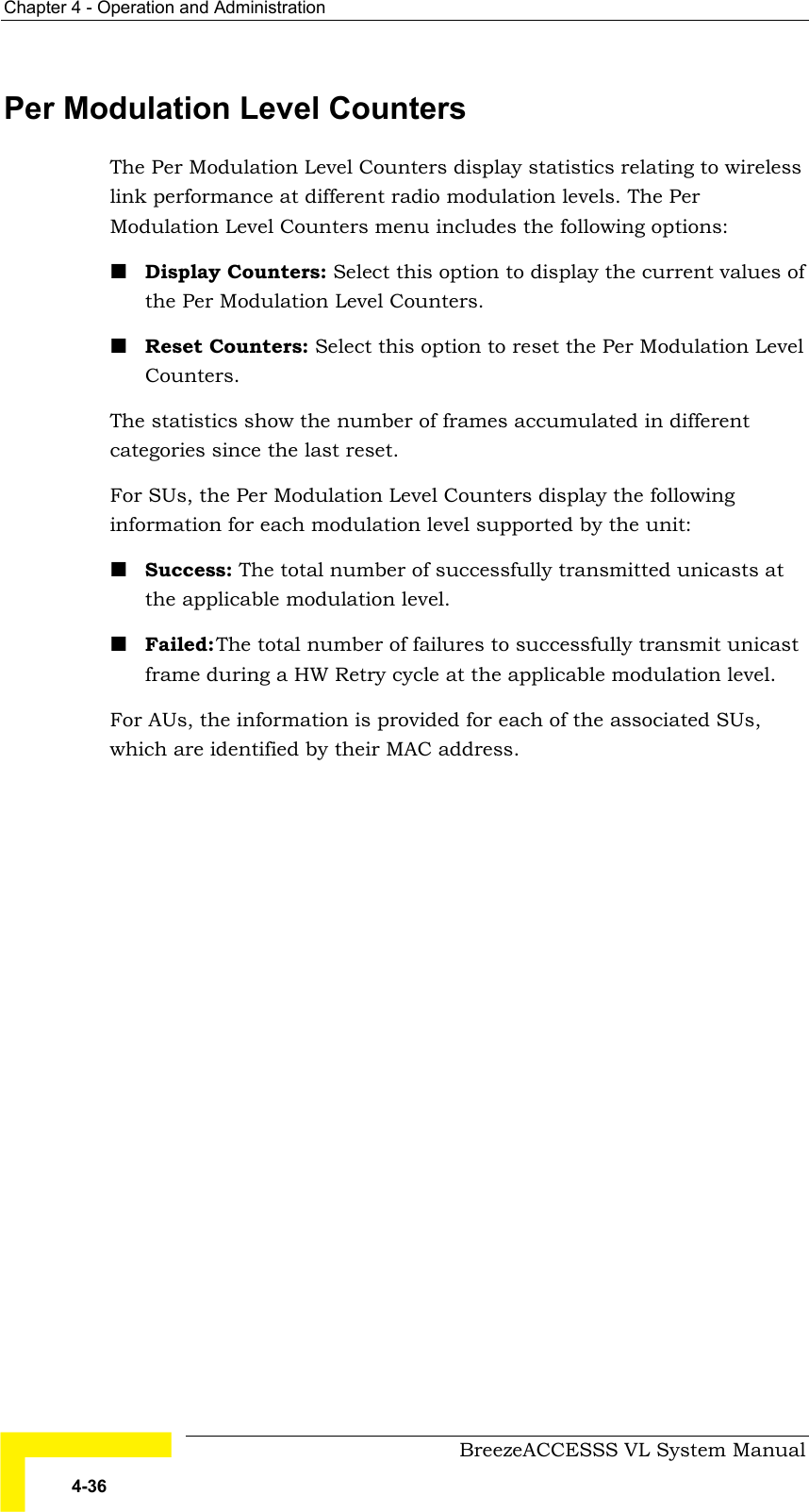
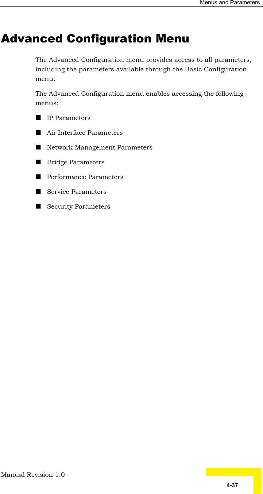
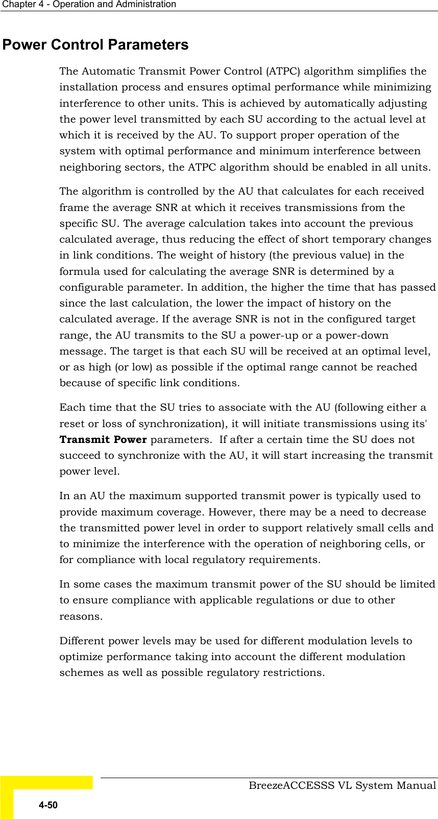
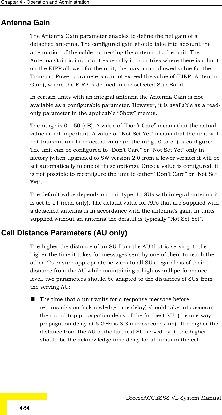
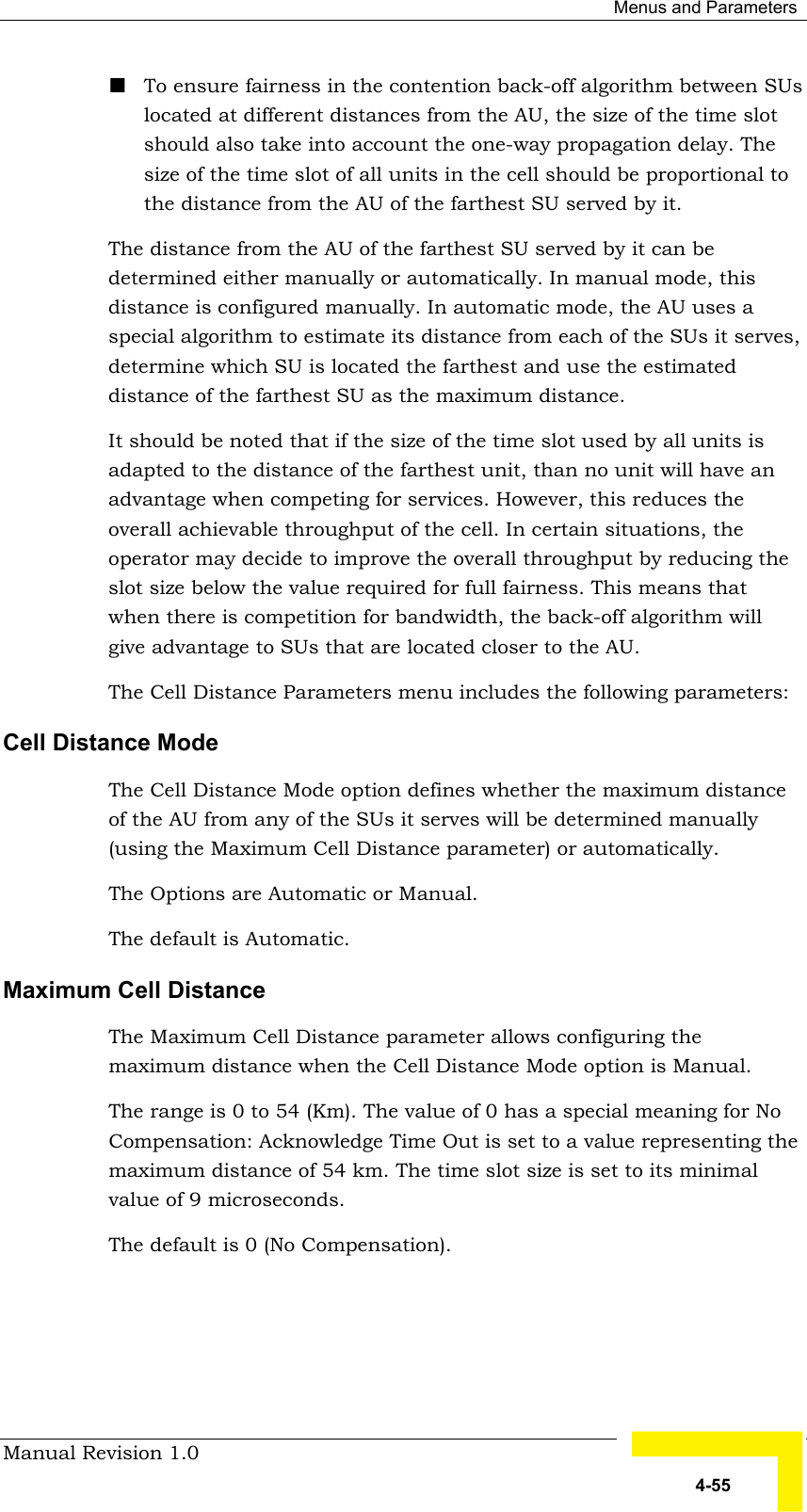
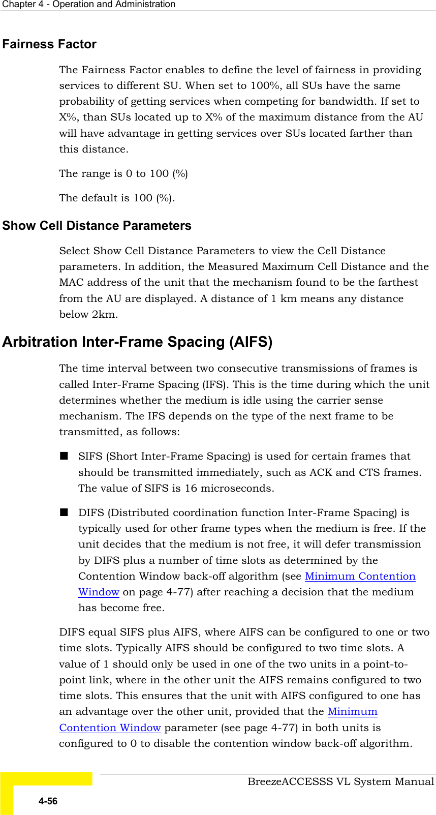
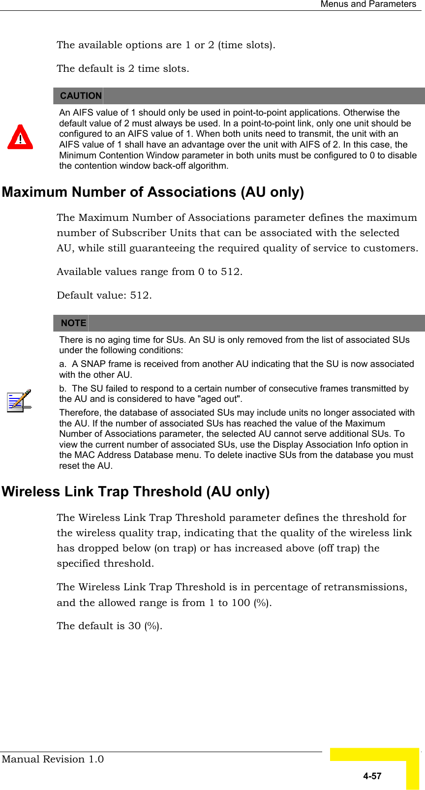
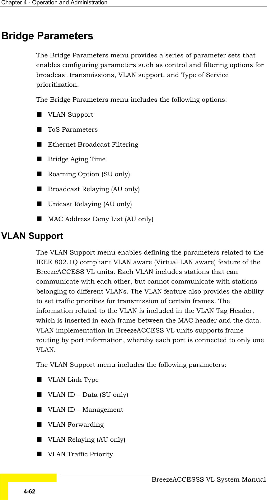
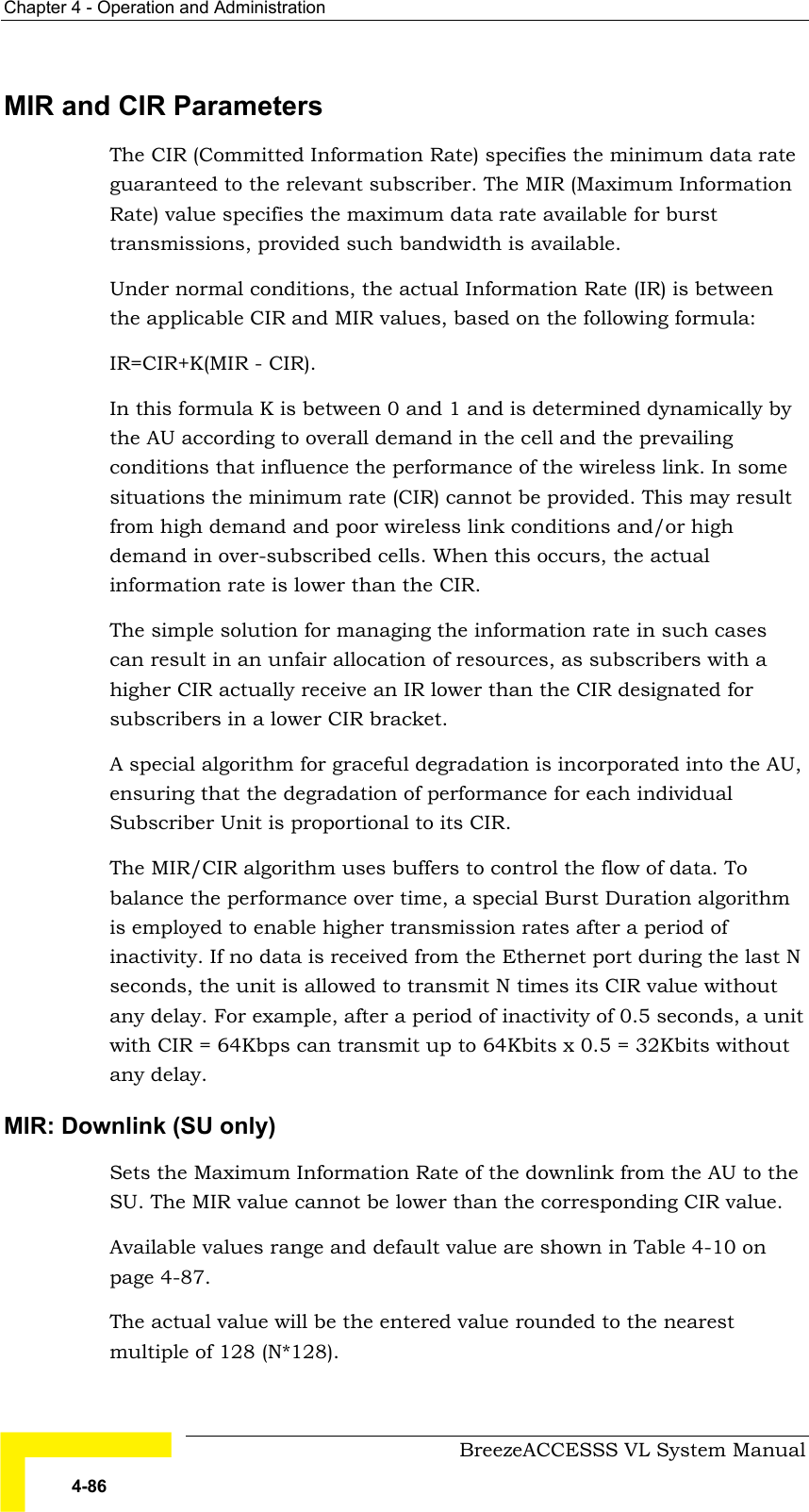
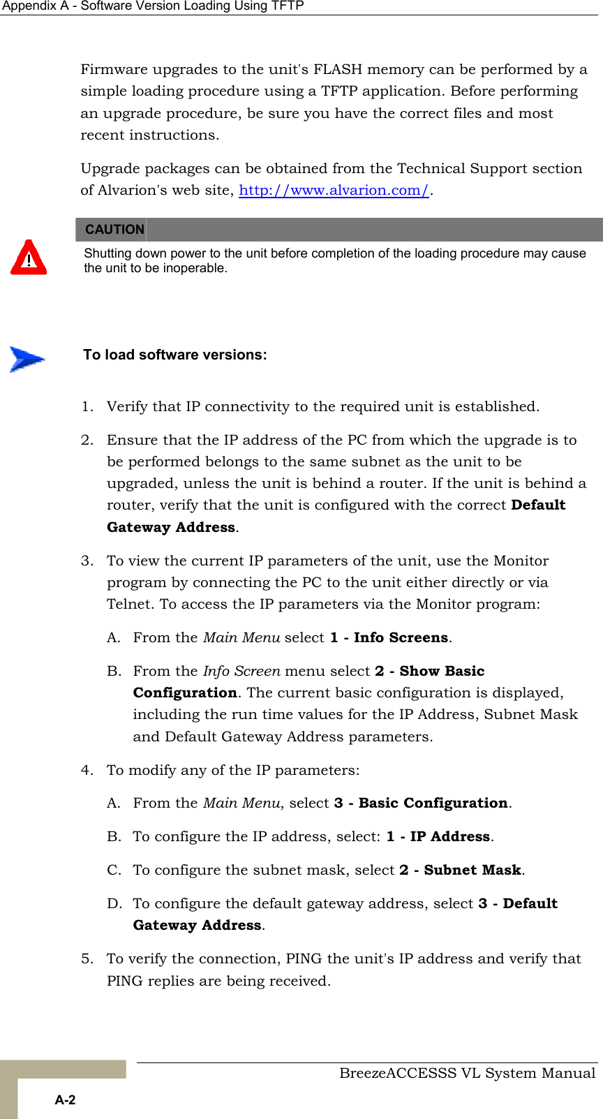
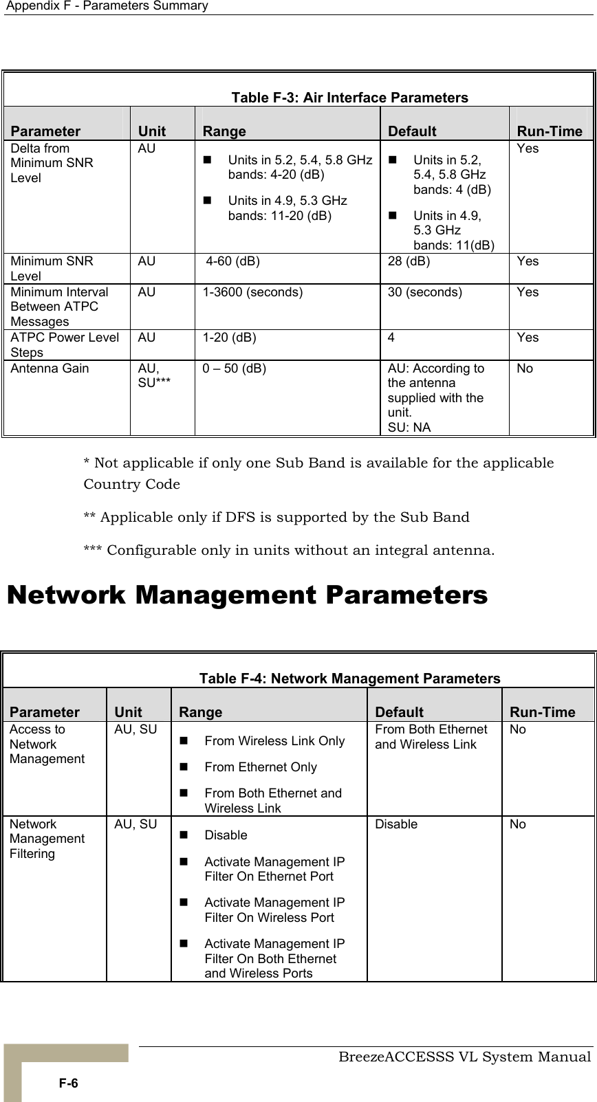
![Menus and Parameters Manual Revision 1.0 A-3 6. Use the TFTP utility, with the following syntax, to perform the upgrade: tftp -i hostaddress put sourcefile [destinationfile] where -i is for binary mode and hostaddress is the IP address of the unit to be upgraded. put causes the PC client to send a file to the hostaddress. 7. The original sourcefile name of SW files supplied by Alvarion is in the structure uX_Y_Z.bz, where u is the unit type (a for AU, s for SU) and X.Y.Z is the version number. 8. destinationfile is the name of the file to be loaded. Use the SNMP write community <SnmpWriteCommunity>.bz to define the destination filename. The default SNMP write community is private. For example, to load the upgrade file a1_0_6.bz to an AU whose IP address is 206.25.63.65: tftp -i 206.25.63.65 put a1_0_6.bz private.bz 9. When the loading is complete, the following message is displayed, indicating completion of the TFTP process: Download operation has been completed successfully 10. The unit decompresses the loaded file and checks the integrity of the new version. The new version replaces the previous shadow version only after verification. If verification tests fail, the loaded version will be rejected. Among other things that are tested, the unit will reject a file if either the file name or the version number matches the current Main versions. The unit will also reject a file designated for a different unit type, e.g. an AU upgrade file with the prefix a in the original file name will not be accepted by SUs. 11. The FLASH memory can store two software versions. One version is called Current and the second version is called Shadow. The new version is loaded into the Shadow (backup) FLASH memory. To check that the new firmware was properly downloaded and verified, view the firmware versions stored in the FLASH, as follows: A. From the Main Menu, select 2 - Unit Control. B. From the Unit Control menu, select 5 - Flash Memory Control. C. From the Flash Memory Control menu, select S - Show Flash Versions. The following information is displayed:](https://usermanual.wiki/Alvarion-Technologies/VL-53.User-Manual/User-Guide-505478-Page-177.png)