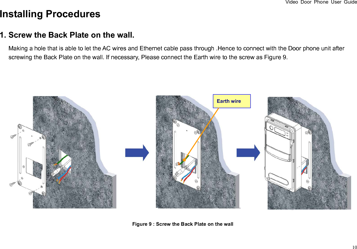
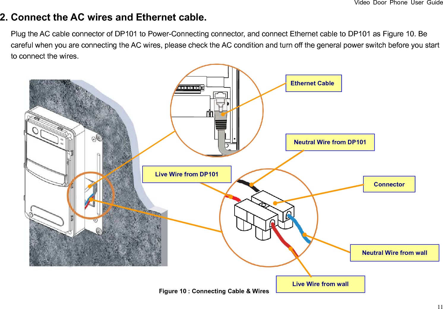
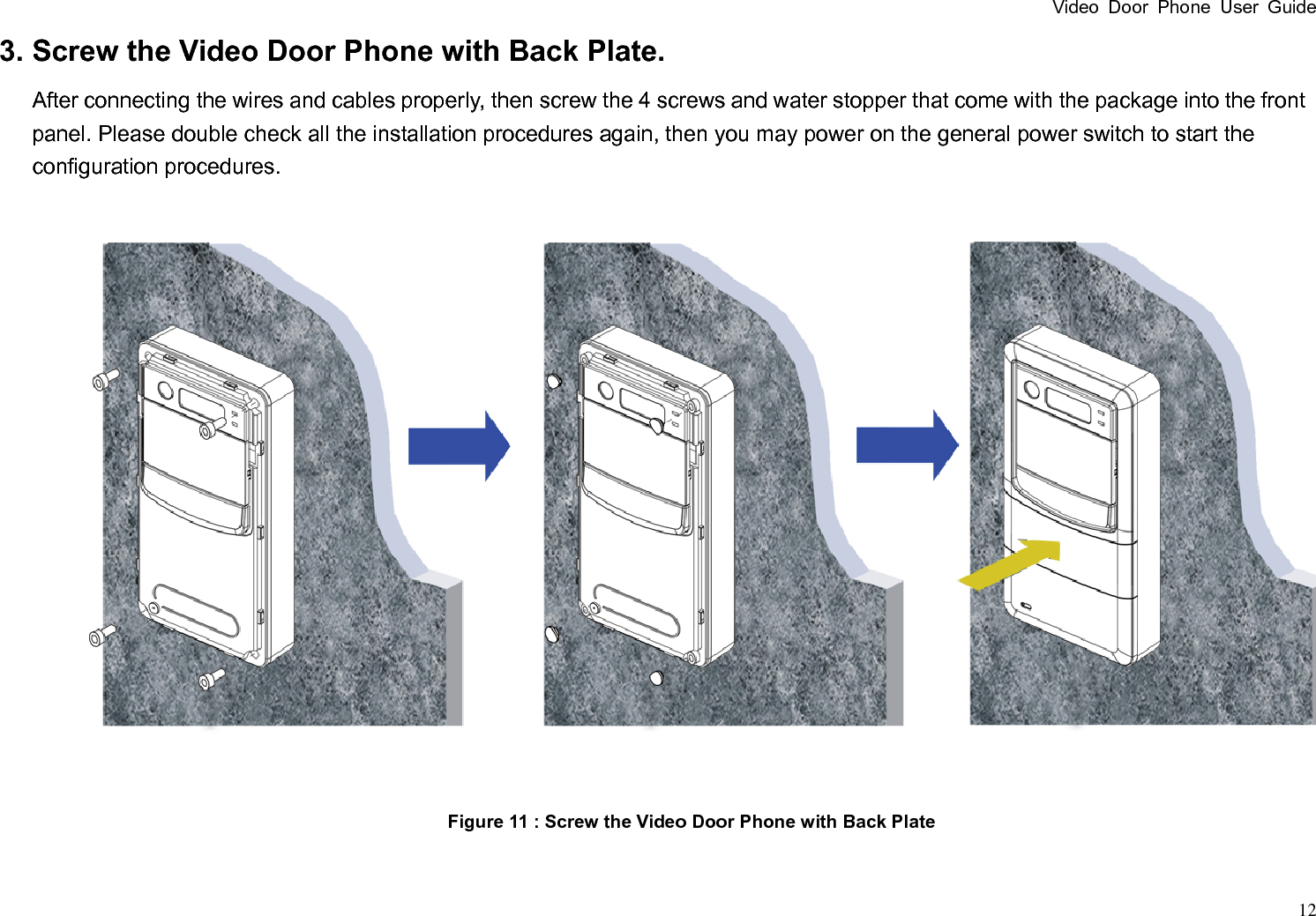
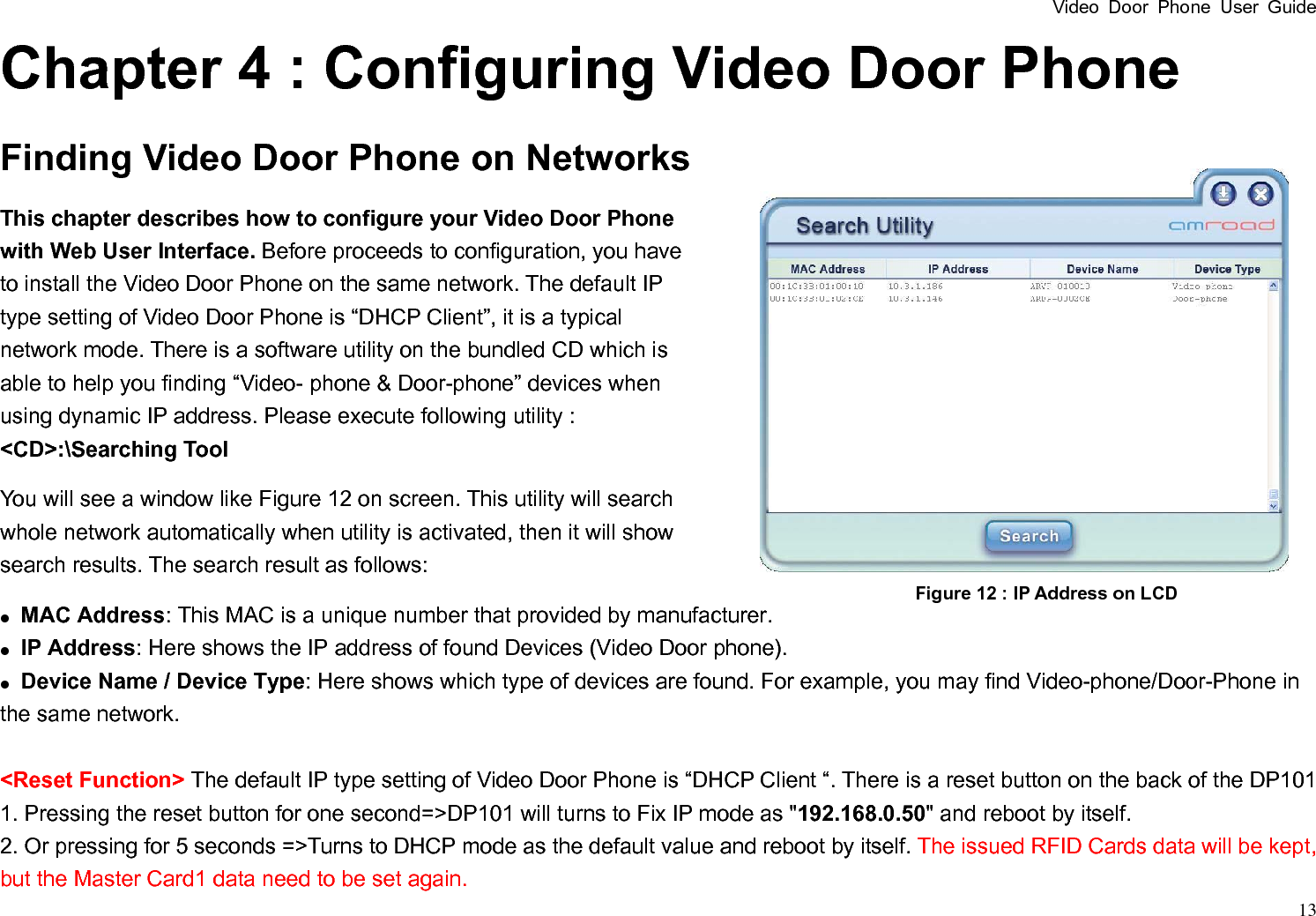
AmRoad Technology ARDP101R Video Door Phone User Manual

AmRoad Technology Inc. Video Door Phone

user manual

Video Door Phone User Guide  1 VIDEO DOOR PHONE USER GUIDE Version: 1.00 Issued Date: 12/10/2009 For Models:    DP101/DP101R/DP101RT/EP101/EP101T (Single Unit)
Contents Chapter 1 :    Introduction  1 Welcome  1 General Application of Door Entry System  2 Use of SIP  4 Chapter 2 :    Knowing Video Door Phone  5 Package Contents  5 Front Panel  6 Rear Panel  7 Dimensions  8 Chapter 3 :    Installing Video Door Phone  9 Suggested Installation Positions  9 Lighting Conditions  9 Installing Procedures  10 1. Screw the Back Plate on the wall.  10 2. Connect the AC wires and Ethernet cable.  11 3. Screw the Video Door Phone with Back Plate.  12 Chapter 4 :    Configuring Video Door Phone  13 Finding Video Door Phone on Networks  13 Entering Web User Interface  14 System - Basic Settings  15 System – Network Settings  16 System - Login ID  17 System - Reboot  17 Phone Settings – Video  18 Phone Settings – Audio  19
Video Door Phone User Guide  1 SIP Services  21 Entrance Settings – Extension  22 Entrance Settings – GPIO  23 Upgrade  26 Configurations  27 Chapter 5 :    Using Video Door Phone  28 Making Calls From Video Door Phone  28 Answering Calls on IP Video Phone  28 Open the Door (Optional function)  28 Chapter 6 :    Applications  30 Functions Performed by the Devices  30 Functions Performed by the GPIO Devices  31 Functions Performed by the IP-PBX  38 Appendix A :    Regulatory Information  39 CE DECLARATION OF CONFORMITY (EUROPE)  40
Video Door Phone User Guide  1 Chapter 1 : Introduction Welcome Thank you for choosing this Video Door Phone. This device is designed to co-work with IP Video Phone to compose a SIP based door entry system. Beside taking advantages of IP technologies, this system also can fully utilize the SIP protocol to link to your SIP VoIP services. Another words, this system is not only performing as an Intercom system, but also work with your Telecom system.  This product provides many extraordinary features:   z Talk to visitors with real time video and voice on IP Video Phone or Softphone on PC. z Optional RFID card reader with embedded RFID card database and entrance log system(DP101R/DP101RT).  z Support SIP (Session Initiation Protocol) VoIP services, it is able to forward visitor calls to your mobile phone or office phone. z Support H.263 and MPEG-4 video formats.   z Support G.711 and G.729 audio formats.   z Build-in wide angle lens and white light-compensator.   z Build-in speaker and microphone.   z Water and dust resistance capabilities (IP53 (DP101RT/EP101T) and IP55 ).   z Friendly web user interface for configuration and management. Please read this user guide carefully before installing device. Please contact your dealers or system integrators if you have questions.
Video Door Phone User Guide  2 Figure 1 : Single Unit Application General Application of Door Entry System There are two major models of Video Door Phone: DP101 series, single unit model. They are applied on different conditions. Please see following descriptions: Single Unit Application DP101 series is designed for units of apartment or single house. Please see Figure 1.  Using a home IP PBX to connect all SIP based devices.  Communicate with each devoice simply with extension numbers.    Connect to SIP VoIP services via Internet.   Community Application DP100 is designed for building, apartment or community. Please see Figure 2  Connect each house or apartment with a large IP PBX.    Residents can check visitors, monitor public areas or call each others with extension numbers.    Connect to SIP VoIP services via Internet.
Video Door Phone User Guide  3                    Figure 2 : Community Application
Video Door Phone User Guide  4 Use of SIP SIP, initial of Session-Initiation-Protocol, it is an application-layer control (signaling) protocol for creating, modifying, and terminating sessions with one or more participants. These sessions include Internet telephone calls, multimedia distribution, and multimedia conferences. Simply say, SIP is a most commonly used protocol that been used to interconnect SIP Enabled PBXes and/or SIP User Agents to each other to establish voice and video sessions between each other over an IP Network.   There are few typical applications of SIP products, please refer to Figure 3:  Make a video phone call from Video Phone A to Video Phone B.  Make a video phone call from softphone on notebook to Video Phone A or Video Phone B.  View SIP Camera video from Video Phone A or Video Phone B.  View SIP Camera video from softphone on your computer.       Figure 3 : General SIP Application
Video Door Phone User Guide  5 Chapter 2 : Knowing Video Door Phone Package Contents The following items are included in your SIP camera package. Check this list before installation to ensure that you have received all items. 1. Front Panel 2. Video Door Phone Unit 3. Back Plate 4. Screw Pack (4 pieces of M4 x 10mm) 5. Wrench 6. Water Stopper (4 pieces of silicon rubber) 7. Screw for Earth Wire 8. Wall mounted screw pack 9. Terminal Connecter 10. Connecter for Power Wire 11. Tool for removing the Front Panel from   Video Door Phone Unit 12. Utility CD Please contact your dealer immediately if items are missing. Figure 4 : Package Contents
Video Door Phone User Guide  6 Front Panel        Lens ModuleIR LEDLED Speaker Door BellMicrophoneFigure 5 : Front Panel
Video Door Phone User Guide  7 Rear Panel  Figure 6 : Rear Panel and Connectors Figure 6 : Rear Panel and Connectors Terminal ConnectorPack 1 Ethernet RJ45 Connector AC Cable of DP101 Reset Button Alarm Sensor
Video Door Phone User Guide  8 Dimensions Figure 7 : Dimensions 40 mm 120 mm 230 mm
Video Door Phone User Guide  9 Chapter 3 : Installing Video Door Phone Suggested Installation Positions Due to the view angle of the camera is limited, therefore the installation position for Video Door Phone is crucial. In order to get a better view, the view angle of this door phone should be around 85. Also the height of the lens position is suggested between 155cm to 160cm according to building conditions. For more details please refer to Figure 8.  Lighting Conditions In order to get better visual quality, this product requires external lighting auxiliary at night or lower light condition. Please refer to Page 29. The Lens of this device is able to see IR (Infra-Red) light, therefore you may also implement with an IR light. IR light only delivers black & white image, and the objects looks odd in some conditions. Please see the spotlight example on Figure 8.     Figure 8 : Installation Example
Video Door Phone User Guide  10 Installing Procedures 1. Screw the Back Plate on the wall. Making a hole that is able to let the AC wires and Ethernet cable pass through .Hence to connect with the Door phone unit after screwing the Back Plate on the wall. If necessary, Please connect the Earth wire to the screw as Figure 9.    Figure 9 : Screw the Back Plate on the wall Earth wire
Video Door Phone User Guide  11 2. Connect the AC wires and Ethernet cable. Plug the AC cable connector of DP101 to Power-Connecting connector, and connect Ethernet cable to DP101 as Figure 10. Be careful when you are connecting the AC wires, please check the AC condition and turn off the general power switch before you start to connect the wires.      Ethernet Cable Figure 10 : Connecting Cable & Wires Neutral Wire from DP101 Connector Live Wire from DP101 Neutral Wire from wall Live Wire from wall
Video Door Phone User Guide  12 3. Screw the Video Door Phone with Back Plate. After connecting the wires and cables properly, then screw the 4 screws and water stopper that come with the package into the front panel. Please double check all the installation procedures again, then you may power on the general power switch to start the configuration procedures.                 Figure 11 : Screw the Video Door Phone with Back Plate
Video Door Phone User Guide  13 Chapter 4 : Configuring Video Door Phone Finding Video Door Phone on Networks This chapter describes how to configure your Video Door Phone with Web User Interface. Before proceeds to configuration, you have to install the Video Door Phone on the same network. The default IP type setting of Video Door Phone is “DHCP Client”, it is a typical network mode. There is a software utility on the bundled CD which is able to help you finding “Video- phone & Door-phone” devices when using dynamic IP address. Please execute following utility :   <CD>:\Searching Tool You will see a window like Figure 12 on screen. This utility will search whole network automatically when utility is activated, then it will show search results. The search result as follows: z  MAC Address: This MAC is a unique number that provided by manufacturer. z  IP Address: Here shows the IP address of found Devices (Video Door phone). z  Device Name / Device Type: Here shows which type of devices are found. For example, you may find Video-phone/Door-Phone in the same network.  <Reset Function> The default IP type setting of Video Door Phone is “DHCP Client “. There is a reset button on the back of the DP101 1. Pressing the reset button for one second=>DP101 will turns to Fix IP mode as "192.168.0.50" and reboot by itself. 2. Or pressing for 5 seconds =>Turns to DHCP mode as the default value and reboot by itself. The issued RFID Cards data will be kept, but the Master Card1 data need to be set again.   Figure 12 : IP Address on LCD
Video Door Phone User Guide  14 Entering Web User Interface Input the IP address of this product on your browser, then you will see home page of the Video Door Phone like Figure 13.   Web UI is protected by Login ID and Password. Press the “Login” button, then you will see 2 input fields: Login ID and Password. Please key in the correct ID and password, and then press second “Login” button to enter Web UI. The default ID and password are: Login ID: admin Password: admin  Figure 13 : Login Web UI
Video Door Phone User Guide  15 System - Basic Settings Device ID – This ID is a unique number that assigned by manufacturer. Device Name – The field allows user to give a specified name for identification such as “Smith Family”. Date & Time – Here shows date and time set on this phone. Set New Date & Time – These fields allow user to set correct date and time according to the local standard. You may synchronize phone time to match your PC by press “Sync with PC” button or save changed date and time. Time Zone – Here allows you to select preferred time zone to fit your location. You can enable the “Daylight-Saving” feature if needed.   Network Time Protocol – Enable this protocol allows the system to calibrate the time with NTP server through Internet.   NTP Server Address – You may use your preferred NTP server by input new address here. Calibration Schedule – You may select when that you wish to do this NTP calibration. Auxiliary Light – This feature allows you to control internal door bell button and external lighting device via DO1(Digit Output 1). z Service : You may enable or disable this function. z Control Status : You can select turn on or turn off the external light when timer is started. z Start Time : You may set start time here. z End Time : You may set end time here. z Device Location : The field allows user to give a device location for identification such as “West Outside light”. Figure 14 : System Basic Settings
Video Door Phone User Guide  16 System – Network Settings MAC Address – This is a quasi-unique identifier attached to most network adapters. IP Type – You may select preferred IP type here. There are two options: DHCP Client and Fixed IP Address. The default value is DHCP Client. If you select Fixed IP Address, you have to input IP address, Subnet Mask, Default Gateway, Primary DNS and Secondary DNS data in following fields. DNS Server Address – You may fill in the Primary DNS and Secondary DNS server address in these fields.    Figure 15 : System Network Settings
Video Door Phone User Guide  17 System - Login ID You may change login ID and password of this Web UI here. There are 3 items: Login ID – Input new ID here.   Password – Input new password here. Confirm Password – Input the new password again here to make sure the inputs are correct.   After filling in preferred data, you may press the “Save” button to save new data.    The default is ID and password: Login ID : admin Password : admin.  System - Reboot You may reboot this phone remotely if needed. Press “Reboot” button to start this action. After confirm rebooting, Web UI will go back to the home page, but the phone may take 60 seconds to go back on line. So you have to wait for at least 90 seconds to login again.     Figure 16 : System Login ID Settings Figure 17 : System Reboot
Video Door Phone User Guide  18 Phone Settings – Video You may set change the video settings in this page. Bandwidth –You may select preferred bandwidth for video and audio streaming. There are 5 options: 128Kbps, 256Kbps, 384Kbps, 512Kbps and 768Kbps. Please check which bandwidth is suitable for you with your service provider. Default setting is 384Kbps. Quality –This item allows you to select preferred video quality. There are 5 options: Excellent, Good, Average, Acceptable and Low. Please note that better quality creates higher bit-rate and requires larger bandwidth. You may see blocky video if you select better quality without enough bandwidth. Default setting is Average. Codec Priority –You may select priority of video codec here: H.263 – will authenticate H.263 first. RTP Port – This item allows you to set a range of port numbers for RTP ports here. There are 2 fields in this item: Start Port Number and Range. Total available ports are from 1024 to 65531, you may select a starting port number and set a range from that port. The default value of Start Port Number is 9000, range is 100. Power Frequency – You may select the power frequency according to your local power specifications. Wrong power frequency may cause the video flicking abnormally. CMOS Static Brightness – This item allows you to adjust the brightness of CMOS according the lighting environment of the installed location. There are 10 levels of value in this item. Lower value makes the video brighter. CMOS Color Balance – This item allows you to adjust the color conditions. Since the Lens of this product is able to take Infra-Red light, it may affect the color of video. You may select a suitable condition from: Fluorescent Light, Yellow Lamps and Orange Lamps.   Figure 18 : Video Settings
Video Door Phone User Guide  19 z Fluorescent Light – This condition is suited for white lighting environment such as office.   z Yellow Lamps – This condition is suited for indoor yellow bulb environment. It is more like sunny daylight in outdoor. z Orange Lamps – This condition is suited for indoor orange color or more red color environments. It is more like sunset or dawn   in outdoor. CMOS Luma detection –You may enable or disable the function of CMOS Luma detection that will turn on IR LED according to the lighting environment of the installed location. The default value is suitable for most of the environment. Please do not change them if you are not familiar with them. Furthermore, if no value is suitable for your environment , please disable the function and turn on/off the IR LED by press ‘5’ toggling. YUV- Ymax(0~255) – You may set the condition to turn off IR LED automatically. The recommend value is 80(preferred),70 or 60. YUV- Ymin(0~255) – You may set the condition to turn on IR LED automatically. The recommend value is 40(preferred),30 or 20.  <IMPORTANT>: Please note, “turn on/off IR LED” and “adjust the brightness of CMOS” via Videophone prior to the “automatic CMOS Luma detection” function. DP101 can’t get the correct value of the CMOS brightness in some environment, please adjust the brightness value via the Videophone in conversation state, or turn on/off IR LED by yourself.    Phone Settings – Audio You may set change the audio settings in this page. Codec Priority – You may select priority of audio codec here: G711/G729 – will authenticate G711 first, then G729. G711/G729 – will authenticate G729 first, then G711.   VAD – You may enable or disable Voice-Active-Detection function here. This phone will detect background noise and send silence  Figure 19 : Audio Settings
Video Door Phone User Guide  20 packet to the other end if this feature is enabled.   CNG – You may enable or disable Comfortable-Noise-Generate function here. This phone will generate background noise when receiving silence packet from the other end if this feature is enabled.     AEC Scene Setting – You may select the AEC(Acoustic Echo Control) scene according the environment of the installed location. General option conditions are “Open Space”, ”Semi-open Space”, ”Corridor” or “User Define”. The “User Define” is not recommended option. When you select “User Define”, the advanced setting will be displayed.   Microphone Volume –This item allows you to adjust the Volume of Microphone according the environment of the installed location. There are 10 levels of value in this item. Default setting is 3. Speaker Volume –This item allows you to adjust the Volume of Speaker according the environment of the installed location. There are 10 levels of value in this item. Default setting is 5.
Video Door Phone User Guide  21 SIP Services You may setup advanced SIP service parameters in this page: Authentication z Display Name – This name will show on the IP phone of called parties. You may fill in the preferred name here. ”Doorphone” is preferred.  z User Number – You may fill in the phone number here, normally it is provided by service provider. To work with IP PBX, you may fill in extension number here. z Account ID –You may fill in your account name of SIP service here. z Account Password – You may fill in the password of your SIP service account here. SIP Proxy Server z Service – You may enable or disable to register the SIP Proxy Server. (only Enable available )   z IP Address – You may fill in the IP address of SIP Proxy Server in this field. SIP Registrar Server z IP Address – You may fill in the IP address of SIP Registrar Server here. z Registrar Expire Time – Here you can input expire time of SIP Registrar Server. The correct expire time shall provide by your service provider. Default time is 3600 seconds. Protocol – You may select network protocol of the SIP service here. There are 2 options: UDP and TCP. Default setting is UDP. Figure 20 : SIP Services Settings
Video Door Phone User Guide  22 Hold Version – You may select the version of the SIP Hold service here. There are 2 options: RFC3264/RFC2543. Default is RFC3264. Session Timer – You can set the session timer here. The range is from 0 to 1800 seconds. Default is 0 second. Media Timer – You can set the no continue media string timer here. The DP101 will discard the connection when the condition is happened. The range is from 0 to 180 seconds. Default is 5 seconds. No Answer Timer – You can select the disconnection timer when no answer the Doorphone. There are 4 options: 15,30,45 or 60 seconds. Default is 15 seconds. Entrance Settings – Extension You may configure call services in this page: Called Party Extension Number – You may fill out the extension number assigned from IP PBX. It will dial to the called party extension number when the Door Bell button is pressed. Internal Alarm, Alarm will be triggered while stealing –You may enable or disable the “Stolen Prevention” function. Please disable this function when the devices are not ready or during the repairing. This function should be enabled all the time. The default setting is “disable”.  z Service –You may enable or disable the function of “Alarm will be triggered while stealing”. z Time for Alert (alarm duration) – You can select the 3mins / Always for notifying when the internal alarm is triggered.   z Notice Number via Message (SIP) –You may fill in the Video phone number here, it will inform the Video Phone when the Figure 21 : Extension Number
Video Door Phone User Guide  23 internal alarm is triggered.   z Notice Number via Message (IP:Port) –You may fill in the IP and port for the PC here, can also report to PC.   External Alarm (connect with DO4) –Where the external alarm device is connected to the DO4 (Pin : Digit Output 4 ). You may enable or disable the voltage polarity in the auxiliary DO4. The function can be triggered by the following trigger points. Please refer to chapter 6.   z Service –You may enable or disable the function. z Door Bell –The action of pressing the door bell on DP101 can be set as a trigger point.   z Trigger By Digit Input 3 – You can set the “Digit Input 3(DI3)” as a trigger point. You may select the voltage polarity “From High to Low” or “From Low to High” for triggering. z Ethernet – Some trusted Ethernets can be set up as a trigger point. Please contact with the provider when you need more information. z Device Location : The field allows user to give a device location for identification such as “1st Floor West”.  <IMPORTANT>: Please note, all the connection of GPIO MUST be careful. Especially the default polar voltage of hardware (digit output pins) is high. Please select and set the related electric circuit to meet the hardware initial voltage.     Entrance Settings – GPIO You may configure GPIO in this page: Auxiliary Digit Output 2 – Where some external device is (devices are) connected to the DO2(Pin : Digit Output 2). You may enable or disable the voltage polarity changeable in the auxiliary DO2. The function can be triggered by the following ways. Please refer to chapter 6. Figure 22 : GPIO setting
Video Door Phone User Guide  24  z Function Name –You may fill out the function for memo. z Trigger By Digit Input 1 – You can set the “Digit Input 1(DI1)” as a trigger point. You may select the voltage polarity “From High to Low” or “From Low to High” for triggering. z Trigger By Digit Input 2 – You can set the “Digit Input 2(DI2)” as a trigger point. You may select the voltage polar “From High to Low” or “From Low to High” for triggering. z Ethernet – Some trusted Ethernets can be set up as a trigger point. Please contact with the provider when you need more information. z Reporting By Calling Extension Number –You may enable or disable the internal alarm function here. The internal alarm will also call out to the Video Phone when the Digit Output 2 is triggered. And the Video Phone will get the announcement when it answers the call. Where the “call out“ number is same as the “Called Party Extension Number” in WEB “Entrance Settings – Extension” page. z Time for Alert (Alarm duration) – You can select 3mins / Always for the duration when the DO2 function is triggered.   z Notice Number via Message (SIP) –You may fill in the extension number here, it will send SIP Message to the extension when the internal alarm is triggered.   z Notice Number via Message (IP :Port) –You may fill in the IP and port for the PC here, It will report to PC when the internal alarm is triggered z Device Location : The field allows user to clarify the device location for indication such as “1st Floor West”.  <IMPORTANT>: Please note, all the connection of GPIO MUST be careful. Especially the default polar voltage of hardware (digit output pins) is high. Please select and set the related electric circuit to meet the hardware initial voltage.
Video Door Phone User Guide  25 Entrance Settings –RFID   You may get the related RFID information and delete the issued RFID Cards here. Master Card1 – The master card can issue new cards for the new residents. When the field is null, you may scan a new RFID Card, it can be set as Master Card1. Master Card2 – The master card can issue new cards for the new residents. The Master Card2 can be issued by the Amroad’s software. Add User Function by Master Card – To allow the master card can issue new cards for the new residents. Numbers of RFID Card User – The numbers of RFID cards are issued. Export CSV File – The list of issued RFID cards can be exported here. Erase ALL RFID Cards Function – To delete the issued RFID cards can be executed here. When the function is set “Enable”, to erase individual RFID icon will appear as : Erase RFID Number – Then you may input the specific issued RFID card to delete. Figure 24 : RFID
Video Door Phone User Guide  26  Upgrade This section allows you to upgrade firmware of DP101 through network. There are 2 items in this page:   Software Version - Shows current firmware version number. Select Target File - You may press “Browse” button to locate the new firmware that you wish to upgrade. After select the new firmware, you can press “Upgrade” button to start the upgrading process. You will see progress bar showing the upgrade status. <IMPORTANT>: Please note, DO NOT turn off or disconnect the power when the process is still going on, you may cause unrecoverable damage to this Door phone. Continuous orange light will indicate the upgrade procedure still carry on. Figure 23 : Upgrade
Video Door Phone User Guide  27 Configurations This section allows you to backup / restore the configure file. There are 2 items in this page:   Export File –   Backup the configure setting to your external storage. See Fig.24 Import File –   Restore the configure setting from the backup file. See Fig.25.     Figure 24 : Export File Figure 25 : Import File
Video Door Phone User Guide  28 Chapter 5 : Using Video Door Phone Making Calls From Video Door Phone Using the Video Door Phone is quite simple. You will see “Door bell” on the front side .   Press “Door Bell” to make a call.   If there is no one answering this call, the bell sounds (Ding-Dong) will continuously ring until caller cancel this call by pressing again or the call will be disconnected automatically after 15 seconds. (The time out can be set at Web for 15 ,30 , 45 and 60 seconds). Answering Calls on IP Video Phone To answer the call from Video Door Phone on IP Video Phone is same as normal call. You may answer with following ways: z Pick up the handset. z Press the SPEAKER button. z Press “Answer” soft-function key.  Open the Door (Optional function) You may press the “#” key of Video phone to open the door with electronic door lock during answering the call, but should add an extender relay board to connect with Electronic-door-lock. Please refer to Application chapter (Controller Function).   Figure 26 : Door Bell
Video Door Phone User Guide  29 DP101 RFID Card Usage Residents scan RFID card on the reader. DP101R will verify the database to determine whether drive the Digit Output 3. Issue RFID Master Card First Time Without any cabling, just scan RFID card on the DP101R reader when the DP101R device 1st time on-line. The RFID card will be seen as Master Card1.     Upgrade new cards with Master Card : Scan Master Card on DP101R First. Then Scan New RFID Card on DP101R, DP101R Will Store New ID Into Database.
Video Door Phone User Guide  30  Chapter 6 : Applications   Functions Performed by the Devices Stolen prevention Web UI of reporting system set up -Able to set on/off this reporting function -When the reporting function is triggered, other external devices (Digit Output 4) can be triggered to call the police and notify the Videophone (Notice) as well  Functional description -There are more than one way to receive the messages besides the alarm, for instance if the Notice connected to SIP or IP is selected, the messages will be delivered to video phone or external devices correspondingly via TCP/IP Socket.   -(Optional) If the Digit Output 4 is selected, the voltage change status will be transmitted.  Wiring set up (Optional) Please refer to page35 for wiring set up details. Lighting condition Function Scene scenario − When the image is too dark on the videophone display due to the low light situation. Please refer the following step to access IR LED module : - Pressing “5”on Videophone to turn on the IR LED module, press again to turn it off.
Video Door Phone User Guide  31 Functions Performed by the GPIO Devices Lighting condition Function Scene scenario − When the image is too dark on the videophone’s display due to the low light situationPlease refer the following steps: (1) IR LED module − Pressing “5”on Videophone to turn on the IR LED module, press again to turn it off.   On the IR LED mode, the feature of the face can be recognized with black and white image (2) External lighting Source − If an external lighting sources is installed (DO1), pressing “0” on videophone to turn on the (DO1) external lighting source (two sounds of assign ringtone will indicate turn on status), pressing “0” again to turn off the extra light source (one sound of assign ringtone will indicate turn off), can improve the face feature dramatically. (3) Timer Control − When the set time will automatically turn on the external light source. To set up an external light source on web UI (DO1) − Able to turn on /off an external light source function -When this function be triggered, Digit Output 1 will transmit the Polar Reverse. -Or to trigger other devices via Ethernet Functional description − Start up the timer, The voltage status will be transmitted in order to start/end the external light source function -In any time by pressing “0” on the Videophone while calling/answering in order to turn on/off an external light source devices Figure 27 : Auxiliary Light Setting
Video Door Phone User Guide  32  Wiring set up To trigger SSR (Solid State Relay) with the internal power supply to turn on          Burglar prevention Function Scene scenario − Able to set on the setting (DI4) or set off the bugler alarm at home   (1) Normal Close Various sensors are installed at home such as burglar prevention detected sensor (DI1/DI2 is connected with magnetic switches, glass vibration sensor, PIR …).    The burglar prevention function can be turn on/off by DI4. Normally, burglar prevention function will not be turn on while people at home until ready to sleep. The alarm with high pitch frequency will be triggered by DO2 in order to warning the burglar and to report to host by calling with the pre-setting phone number if the any DI1/DI2 has changed the voltage status. (2) Normal Open While using smoke /gas detection sensor and emergency button for safety, the safety mode function should be on all the time if there is any false/error reporting situation occurs, the alarm can be set off by DI4 Figure 28 : Auxiliary Light Wiring
Video Door Phone User Guide  33  Normal close situation can be use with the burglar prevention scenario Web UI of buglar prevention (DO2) - Able to turn on/off this function - When the function is triggered, Digit Output 2 will transmit the Polar Reverse - When the function is triggered other devices can be triggered via  (1) Ethernet (2) Videophone (Notice)  (3)  Can set up the emergency number , there are different internal alarm output indication   (4)  Internal speaker alarm  Wiring set up (DI1/DI2 Wiring set up) Figure 29 : Burglar Prevention Setting Figure 30 : Burglar Alarm Wiring
Video Door Phone User Guide  34          Controller Function Scene scenario − To provide a DO2 that can connect to the Digital input of other controller (e.g. Alarm or Door Access controller).  Functional description − During talking, you may press “#” key of Video phone to trigger DO2.Polar reverse will be activated for 5 seconds to access the controller.      Wiring set up Please refer to Fig. 30. Use the controller or SSR (Solid State Relay) to have further applications. Figure 31 : Burglar Device Wiring Figure 32 : Burglar Device Wiring
Video Door Phone User Guide  35 Care Unit Function Scene scenario − The patient can ask the help from the nurses by pressing the door bell button in the care unit .While the meantime the DO4 will receive the turn on signal, if there is a external emergency light on the entrance of the unit in order to notify nurses around.   To turn off the emergency light by set off the DO4 via DI4. If the nurses are not able to be in the care unit immediately then the nurses can answer the phone first to see the situation of the patient before some one reach them. The light and the urgent light on the videophone will not be turning off until someone notice. The restart DI4 to turn off the light and other functions  Web UI setting (DO4) − DI3 is selected in the DO4 or select “Door Bell" function − Digit Output 4 will transmit the Polar Reverse according from setting to notify the external warning light Functional description − To trigger DO4 to call the intercom in the nurse station   1.    By pressing the button of the intercom to call the nurses     2.    Pressing DI3 (emergency button) − To set up/off DI4 or disable the function of the external warning light     Figure 33 : Care Unit Function Setting
Video Door Phone User Guide  36 Wiring set up           Figure 34 : Emergency Button Wiring Figure 35 : External Alarm Wiring
Video Door Phone User Guide  37 Hearing-Impaired Function Scene scenario When a visitor presses the door bell on the DP101, the corresponding pre-set video phone will start to ring and in the meantime the warning light will be turn on to notify the people having the hearting problem. Then they can verify the identity on the screen before they unlock the door. Web UI of Led light set up (DO4)   - The “Door Bell " in DO4 is selected - Digit Output 4 will transmit the Polar Reverse according form setting, in order to activate the LED light    Functional description -  To trigger (DO4): Pressing the button on the intercom to call the pre-set video phone -  To set on/off DI4 or to disable this function  Wiring set up  Figure 37 : External Alarm Wiring Figure 36 : Impaired Function Setting
Video Door Phone User Guide  38 Functions Performed by the IP-PBX Simultaneous Ring –The Distribution Policy is set to Ring All. e.g. When a visitor calls the group call (say extension 500), group members (say extensions 155, 157, and 166) will all ring simultaneously.  Call Forwarding – Enter a number to which incoming calls are forwarded when not answered. The number could be an extension or a PSTN number with appropriate outbound prefix.  E-Mail/Voicemail Notification – IP PBX has a built-in voice mail subsystem with a sophisticated IVR menu. A call to an extension no answer could be configured to enter voice mail recording procedure. After leaving a message, a notification e-mail will be sent to the user owns the extension with or without the message in the form of an attached WAV file.  Figure 38 : Voicemail Notification Setting
Video Door Phone User Guide  39 Appendix A : Regulatory Information FCC STATEMENT This product has been tested and complies with the specifications for a Class B digital device, pursuant to Part 15 of the FCC Rules. These limits are designed to provide reasonable protection against harmful interference in a residential installation. This equipment generates, uses, and can radiate radio frequency energy and, if not installed and used according to the instructions, may cause harmful interference to radio communications. However, there is no guarantee that interference will not occur in a particular installation. If this equipment does cause harmful interference to radio or television reception, which is found by turning the equipment off and on, the user is encouraged to try to correct the interference by one or more of the following measures: z  Reorient or relocate the receiving antenna z  Increase the separation between the equipment or devices z  Connect the equipment to an outlet other than the receiver's z  Consult a dealer or an experienced radio/TV technician for assistance  FCC Radiation Exposure Statement This equipment complies with FCC radiation exposure limits set forth for an uncontrolled environment. This equipment should be installed and operated with minimum distance 20cm between the radiator and your body.  “Changes or modifications are not expressly approved by the manufacturer could void the user's authority to operate the equipment.”
Video Door Phone User Guide  40 CE DECLARATION OF CONFORMITY (EUROPE) Manufacturer declares that this product conforms to the specifications listed below, following the provisions of the European R&TTE directive 1999/5/EC: z  EN 301 489-1, 301 489-17 General EMC requirements for Radio equipment. z  EN 609 50 Safety z  EN 300-328-1, EN 300-328-2 Technical requirements for Radio equipment. Caution: This equipment is intended to be used in all EU and EFTA countries. Outdoor use may be restricted to certain frequencies and/or may require a license for operation. Contact local Authority for procedure to follow. Note: Combinations of power levels and antennas resulting in a radiated power level of above 100 mW equivalent isotropic radiated power (EIRP) are considered as not compliant with the above mentioned directive and are not allowed for use within the European community and countries that have adopted the European R&TTE directive 1999/5/EC.

Navigation menu