AmRoad Technology ARDP3010 Video door phone User Manual DP3010R SI MANUAL 2012 0117
AmRoad Technology Inc. Video door phone DP3010R SI MANUAL 2012 0117
Users Manual

COPYRIGHT
Copyright
© 2011 Amroad Technology Inc.
All Rights Reserved. No part of this publication may be reproduced, transmitted, transcribed, stored in a retrieval system or translated into
any language in any form or by any means without the express written permission of Amroad Technology Inc. To obtain consent, write to the
attention of Amroad Technology Inc.
Document No. DP3010R 2011-1125
www.amroad.com.tw
DISCLAIMER
Amroad reserves the right to change product specification without prior notice.
Changes may be made to the information in this publication without obligation to notify. Amroad shall not be liable for technical or editorial
errors contained herein.
TRADE MARKS
Amroad logo is copyright of Amroad Technology Inc. All other products, services or trade marks mentioned in this document are the
property of their respective owners, companies or organizations.
CONTENTS
i
Contents
Copyright .........................................................................................................................................................................2
Contents ...........................................................................................................................................................................i
CHAPTER 1: INTRODUCTION ...........................................................................................................................................1
Welcome ..........................................................................................................................................................................1
General Application of Door Entry System.........................................................................................................................3
Use of SIP .........................................................................................................................................................................5
CHAPTER 2 : KNOWING VIDEO DOOR PHONE ....................................................................................................................7
Package Contents .............................................................................................................................................................7
Front Panel .......................................................................................................................................................................9
Rear Panel & Side View....................................................................................................................................................10
Dimensions .................................................................................................................................................................... 11
CHAPTER 3 : INSTALLING VIDEO DOOR PHONE.................................................................................................................13
Suggested Installation Position .......................................................................................................................................13
Lighting Condition ..........................................................................................................................................................13
Installing Procedures.......................................................................................................................................................14
1. Wall Hole Drilling......................................................................................................................................................................14
2. Installing Wall Mounting Box (Flush Mount)............................................................................................................................15
3. Wire and Cable Connection.......................................................................................................................................................18
GPIO (General Purpose Input/Output) & Relay Control ...................................................................................................................19
Connecting to Ground Wire.............................................................................................................................................................20
Fasten Rear Cover and Waterproof Mat...........................................................................................................................................21
CONTENTS
ii
4. Installing DP3010R...................................................................................................................................................................22
Lock DP3010R on the Wall...............................................................................................................................................................23
CHAPTER 4 : USES OF THE DOOR PANEL..........................................................................................................................25
Access the Building or Community ..................................................................................................................................25
Basic and Important Operation .......................................................................................................................................26
System Boot ...................................................................................................................................................................27
DESCRIPTION ...................................................................................................................................................................................27
SCREEN............................................................................................................................................................................................27
System Boot-Up ................................................................................................................................................................................27
Home Screen.....................................................................................................................................................................................28
LCD Screens for Visitor and Resident Operation ...............................................................................................................29
TABLE ..............................................................................................................................................................................................29
DESCRIPTION ...................................................................................................................................................................................29
SCREEN............................................................................................................................................................................................29
Password Entry Screen.......................................................................................................................................................................29
Password Entry Screen.......................................................................................................................................................................29
RFID Entry Screen..............................................................................................................................................................................30
Number Entry Screen.........................................................................................................................................................................32
Security Connection Screen ................................................................................................................................................................34
System Out OF ORDER ...................................................................................................................................................37
Out Of Order ....................................................................................................................................................................................37
System Management Screens..........................................................................................................................................38
System Management Screen ..............................................................................................................................................................38
IP Address Display Screen...................................................................................................................................................................39
Device Restart Screen ........................................................................................................................................................................39
Switch to Static IP .............................................................................................................................................................................40
CONTENTS
Have Your Own Home Screen via Web UI..........................................................................................................................41
DESCRIPTION ...................................................................................................................................................................................41
SCREEN............................................................................................................................................................................................41
Format of Home Screen .....................................................................................................................................................................41
Number Entry Screen....................................................................................................................................................42
DP3010R RFID Card Usage...............................................................................................................................................43
Issue Master RFID Card First Time.......................................................................................................................................................43
Issue a New Card with Master Card:....................................................................................................................................................43
CHAPTER 5 : CONFIGURING VIDEO DOOR PHONE .............................................................................................................45
Finding Video Door Phone on Networks ...........................................................................................................................45
Entering Web User Interface............................................................................................................................................46
System - Basic Settings ...................................................................................................................................................48
System – Network Settings ................................................................................................................................................................50
System - Login Name .....................................................................................................................................................................51
System Login Name...........................................................................................................................................................................51
System Reboot..................................................................................................................................................................................51
Streaming Settings – Video ................................................................................................................................................................52
Streaming Settings – Audio ...............................................................................................................................................................54
SIP Settings.....................................................................................................................................................................55
Entrance Settings – Extensions .....................................................................................................................................58
Entrance Settings – GPIO ................................................................................................................................................62
Entrance Settings –RFID..................................................................................................................................................64
Upgrade –Update............................................................................................................................................................66
Configurations................................................................................................................................................................68
APS ................................................................................................................................................................................71
CONTENTS
iv
Functions Performed by the IP-PBX (Compatible with Amroad IP-PBX) .............................................................................72
APPENDIX A : APPLICATION .........................................................................................................................................75
Electronic Lock..................................................................................................................................................................................75
Electronic Bolt ..................................................................................................................................................................................75
Electronic Strike ................................................................................................................................................................................77
Example of the wiring for Electronic Lock with Open Door Button.........................................................................................................78
Diagram of the wiring for Electronic Lock with Open Door Button ........................................................................................................79
APPENDIX B : REGULATORY INFORMATION .....................................................................................................................81
FCC STATEMENT ...............................................................................................................................................................................81
FCC Radiation Exposure Statement ....................................................................................................................................................81
CE DECLARATION OF CONFORMITY (EUROPE) ...............................................................................................................82
DP3010R VIDEO DOOR PHONE
1
Chapter 1: Introduction
Welcome
Thank you for choosing this Video Door Phone. This device is designed to work as Video Door Phone of large building or
community to form a SIP-based door entry system. Besides taking advantages of IP technologies, this device links to other SIP
devices. It will work with most IP PBX systems supporting audio and video, and it can be configured via a web interface.
This product contains following main features:
Talk to visitors with real time video and voice on IP Video Phone or Video Indoor Station
SIP 2.0 (RFC3261) Compliant
Support H.263 video format.
Support G.711 audio formats.
4.3” TFT LCD Screen (Sunlight Readable)
RFID card reader (ISO14443A/13.56MHz (MIFARE Standard) with embedded RFID card database
Support Peer-to-Peer Mode
Key in address number to access resident
Build-in wide angle lens and white LED light-compensator.
Build-in speaker and microphone.
Water and dust resistance capabilities (IP55).
Scan RFID card or Enter password to open the door
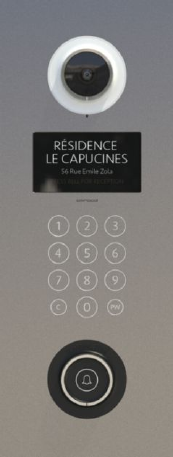
Figure 1: DP3010R

MANUAL FOR SYSTEM INTEGRATOR
2
Support PoE (Power over Ethernet, 802.3af) module (External power supply AC 48V)
Web user interface for configuration and management.
NOTE: The Max Power Consumption of DP3010R is 24W (DC 12V/2A).
Please read this user guide before installing the device. Please contact your dealers or system integrators if you have questions.
DP3010R VIDEO DOOR PHONE
3
General Application of Door Entry System
There are two major series of Video Door
Phone: community series and single unit
series. They are applied on different
conditions. Please see following
descriptions:
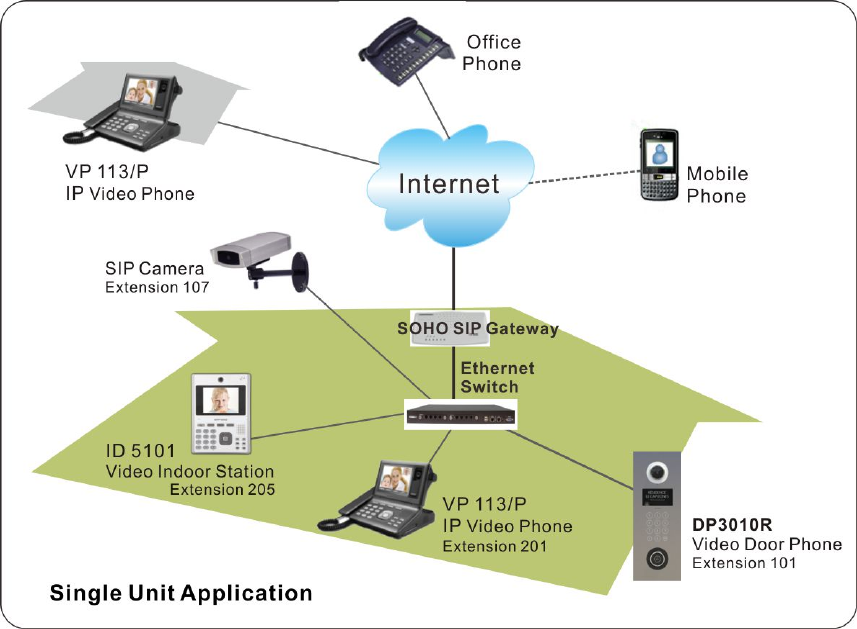
Single Unit Application
Single unit series is designed for units of
apartment or single house. Please see Figure
2 for reference.
Using a home IP PBX to connect all
SIP-based devices.
Communicate with each device simply
with extension numbers.
Connect to SIP VoIP services via Internet.
Figure 2: Single Unit Application
MANUAL FOR SYSTEM INTEGRATOR
4
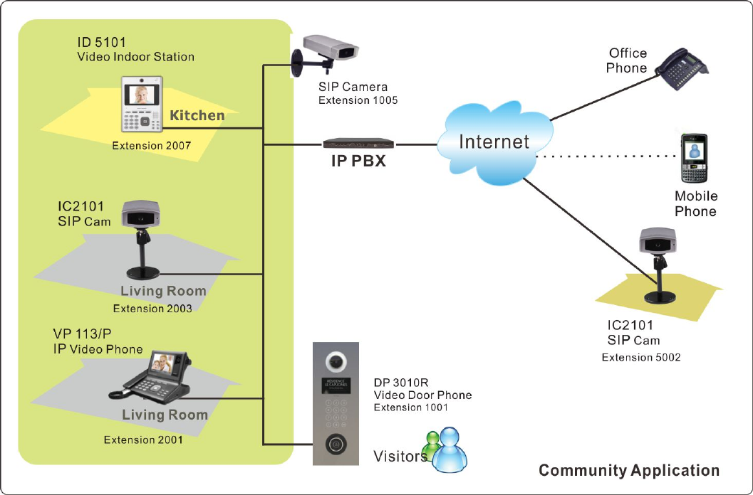
Community Application
Community series is
designed for building,
apartment or
community. Please
contact with your local
dealer about Amroad
DP3010R, and DP100.
Connect each house or
apartment with a
large IP PBX.
Inhabitants can check
visitors with VP113/P,
ID5101, monitor public
areas or call each
others with extension
numbers.
Connect to SIP VoIP services via Internet.
Figure 3: Community Application
DP3010R VIDEO DOOR PHONE
5
Use of SIP
SIP, initial of Session-Initiation-Protocol, it is an application-layer control (signaling) protocol for creating, modifying, and
terminating sessions with
one or more participants.
These sessions include
Internet telephone calls,
multimedia distribution, and
multimedia conferences. In
short, SIP is a most
commonly used protocol
that has been used to
interconnect SIP Enabled
PBXs and/or SIP User Agents
to each other to establish
voice and video sessions
between SIP based devices
over IP Network.
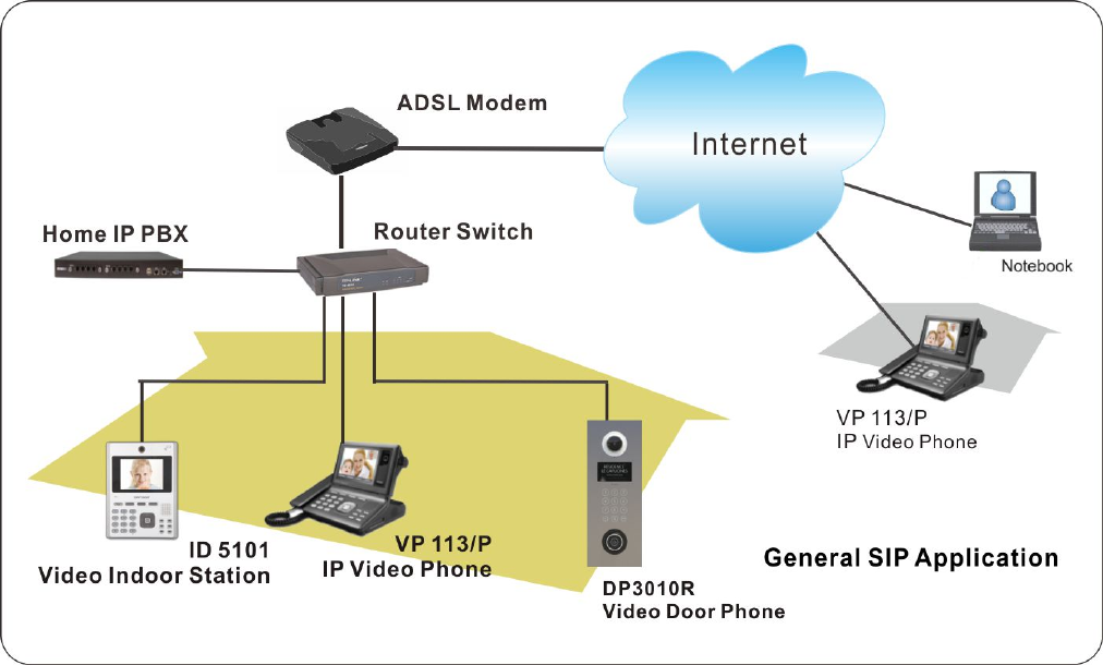
There are few typical applications of SIP products, please refer to Figure 4:
Ring the Door Bell from Video Door Phone (DP3010R) to IP Video Phone (VP113/P)/Video Indoor Station (ID5101)/IPC
Softphone
Figure 4: General SIP Application
MANUAL FOR SYSTEM INTEGRATOR
6
Make a DP3010R live-video view phone call from IPC Softphone /IP Video Phone / Video Indoor station.
Make a video phone call from ID5101 Video Indoor Station to VP113 IP video phone.
View video from softphone on your computer.
DP3010R VIDEO DOOR PHONE
7
Chapter 2 : Knowing Video Door Phone
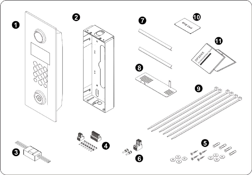
Package Contents
The following items are included in your Video Door Phone package. Check this list before installation to ensure that you
have received all items.
1. Video Door Phone Unit (with protective
cover)
2. Wall Mounting Box (including L-IRON)
3. Relay Board
4. 5-pin Terminal block + 2-pin Terminal
block + Cord End Terminal (7 pieces)
5. Wall Mounted Screw Pack
6. 2-pin Terminal block + Cord End Terminal
(2 pieces)
7. Hang Rod x2
8. Fixing Tool
9. Cable Ties x6
10. Master RFID Card
11. Quick Installation Guide & Quick Start
Guide (English and Chinese)
Figure 5: Package Contents
MANUAL FOR SYSTEM INTEGRATOR
8
Please contact your dealer immediately if any item(s) is missing.
DP3010R VIDEO DOOR PHONE
9
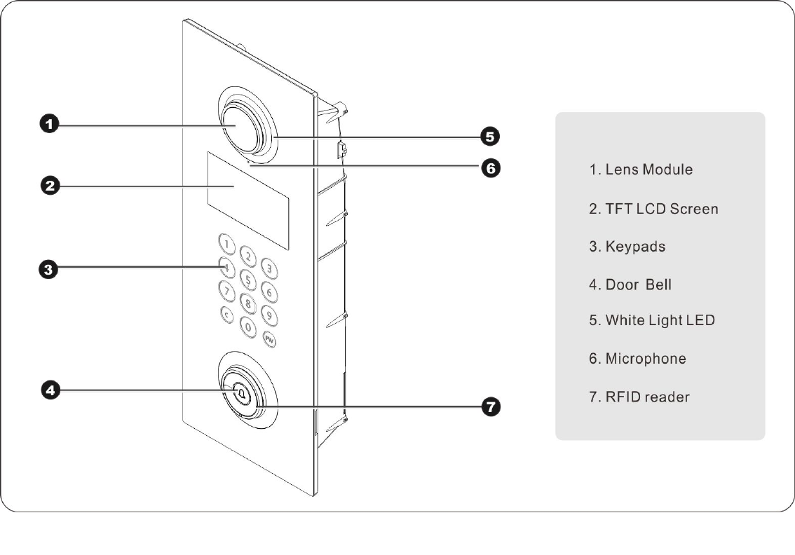
Front Panel
Figure 6: Front Panel
MANUAL FOR SYSTEM INTEGRATOR
10
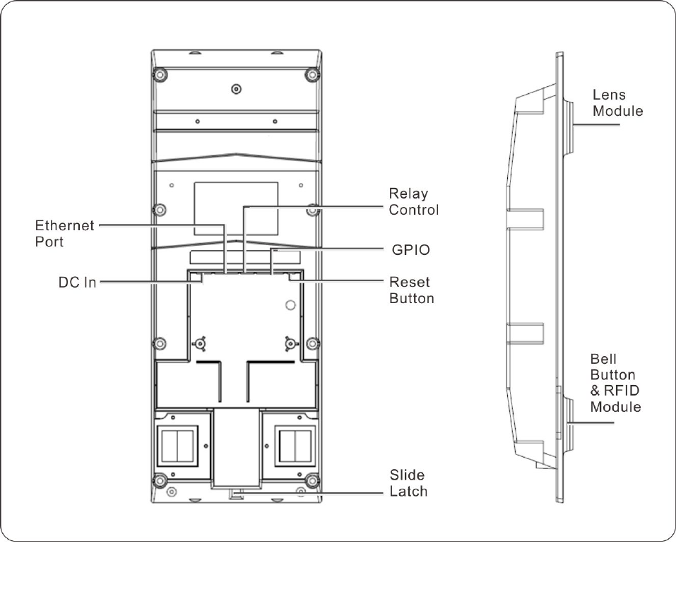
Rear Panel & Side View
Figure 7: Rear Panel & Side View
DP3010R VIDEO DOOR PHONE
11
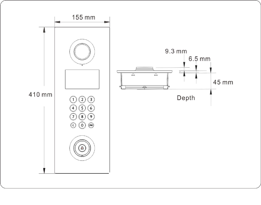
Dimensions
Figure 8: Dimensions
MANUAL FOR SYSTEM INTEGRATOR
12
DP3010R VIDEO DOOR PHONE
13
Chapter 3 : Installing Video Door Phone
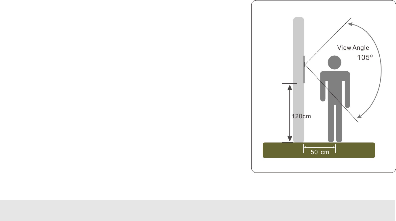
Suggested Installation Position
The view angle of the lens module is limited, so the installation position for Video
Door Phone is crucial. The video door phone comes with a wall mounting box. In
order to get a better view and the view angle of this door phone is around 105o,
the height of the bottom of the wall mounting box is suggested about 120 cm
(please refer to the diagram on next page) far away from the ground according to
building conditions. Please also refer to Figure 9.
Lighting Condition
In order to get better visual quality, this product provides WL (white light) LED
for lighting at night or lower light condition. The Lens of this device is able to see
WL (White Light) LED light. In order to get a better view, the view angle of this
door phone should be less than 105o. (Also the height of the lens position is
suggested at the distance of 155 cm according to building conditions.)
WARNING: Avoid eyes exposure to the beam of the WL (White Light) LED for a long time,
or it may cause discomfort to your eyes.
Figure 9: Suggested Installation Position
MANUAL FOR SYSTEM INTEGRATOR
14
Installing Procedures
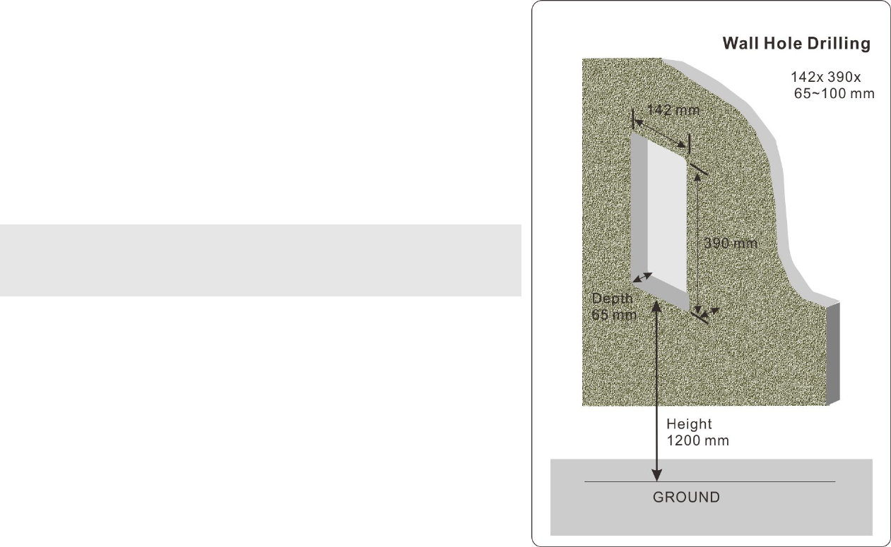
1. Wall Hole Drilling
Drill a rectangular hole the size of 142mmx 390mm on the wall with its
depth 65~100mm. And, it is suggested that the depth should be 65mm
for DP3010R installation. At the same time, the bottom of the
rectangular hole is at a distance of 1200mm (120cm) above the ground.
NOTE: Reserve the space for junction wiring in the wall.
The junction wiring are for Ethernet cable, DC power, Ground
wire, and Relay control.
Figure 10: Wall Hole Drilling
DP3010R VIDEO DOOR PHONE
15
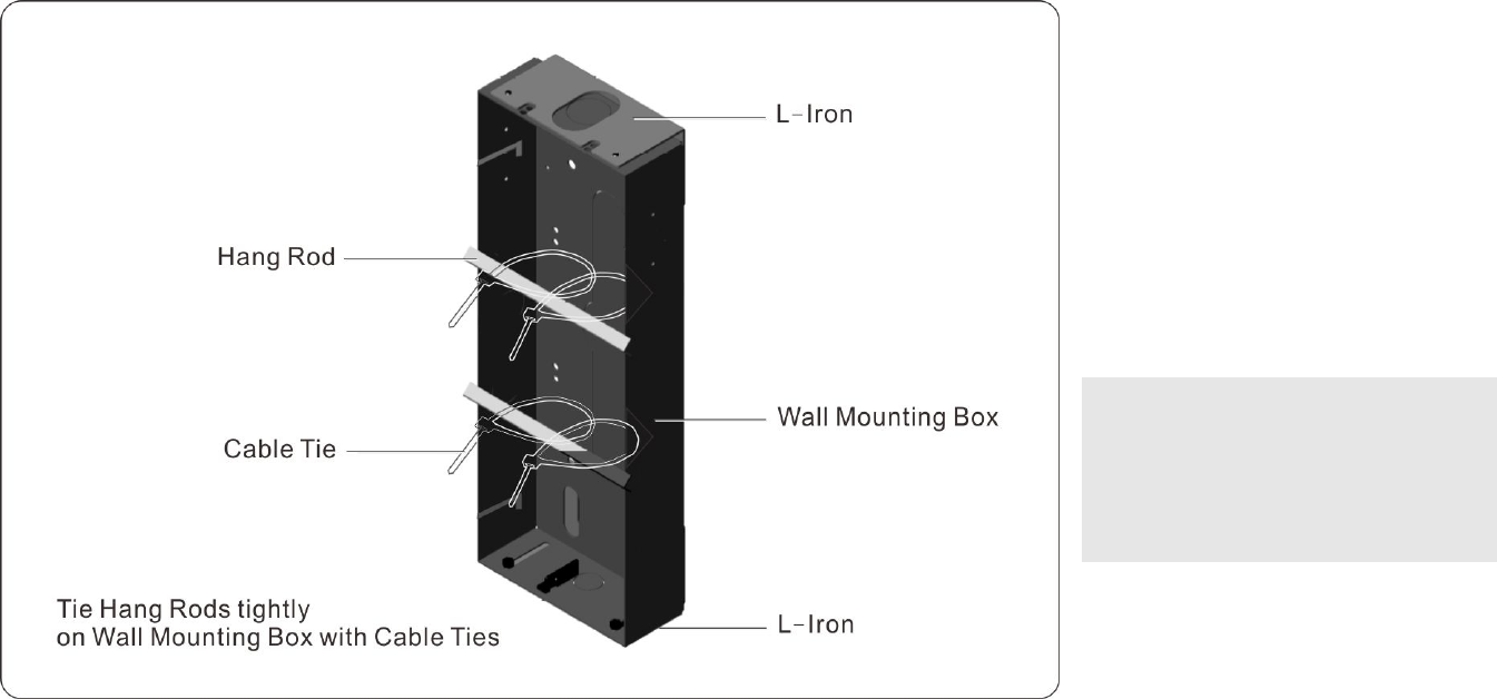
2. Installing Wall Mounting Box (Flush Mount)
Before installing DP3010R on the wall, Wall Mounting Box should be first mounted on the wall. The following diagram shows the
main components and tooling of the wall mounting box of DP3010R.
The procedure for installing wall mounting box is described in details. Take out the main unit and parts from package contents.
Please follow the steps below to installing wall mounting box:
Figure 11: Tie Hang Rods tightly on Wall
Mounting Box with Cable Ties
NOTE:
Hang Rod is used to keep Wall
Mounting Box parallel to the
surface of the wall.
MANUAL FOR SYSTEM INTEGRATOR
16
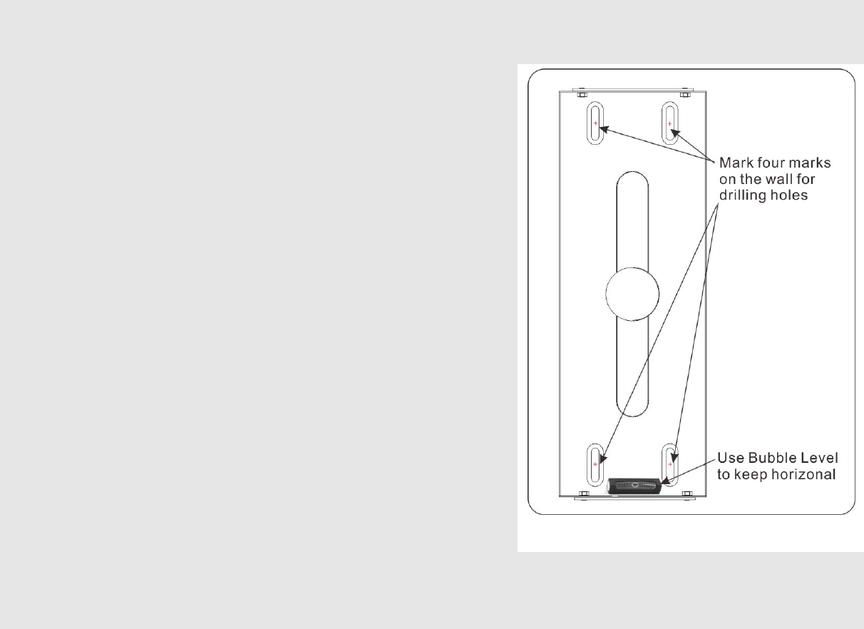
Step 1 Put wall mounting box into wall hole, place a spirit level (bubble level) on the wall mounting box, mark the
four on the wall for drilling holes.
Step 2 Drill four holes for wall screw anchors.
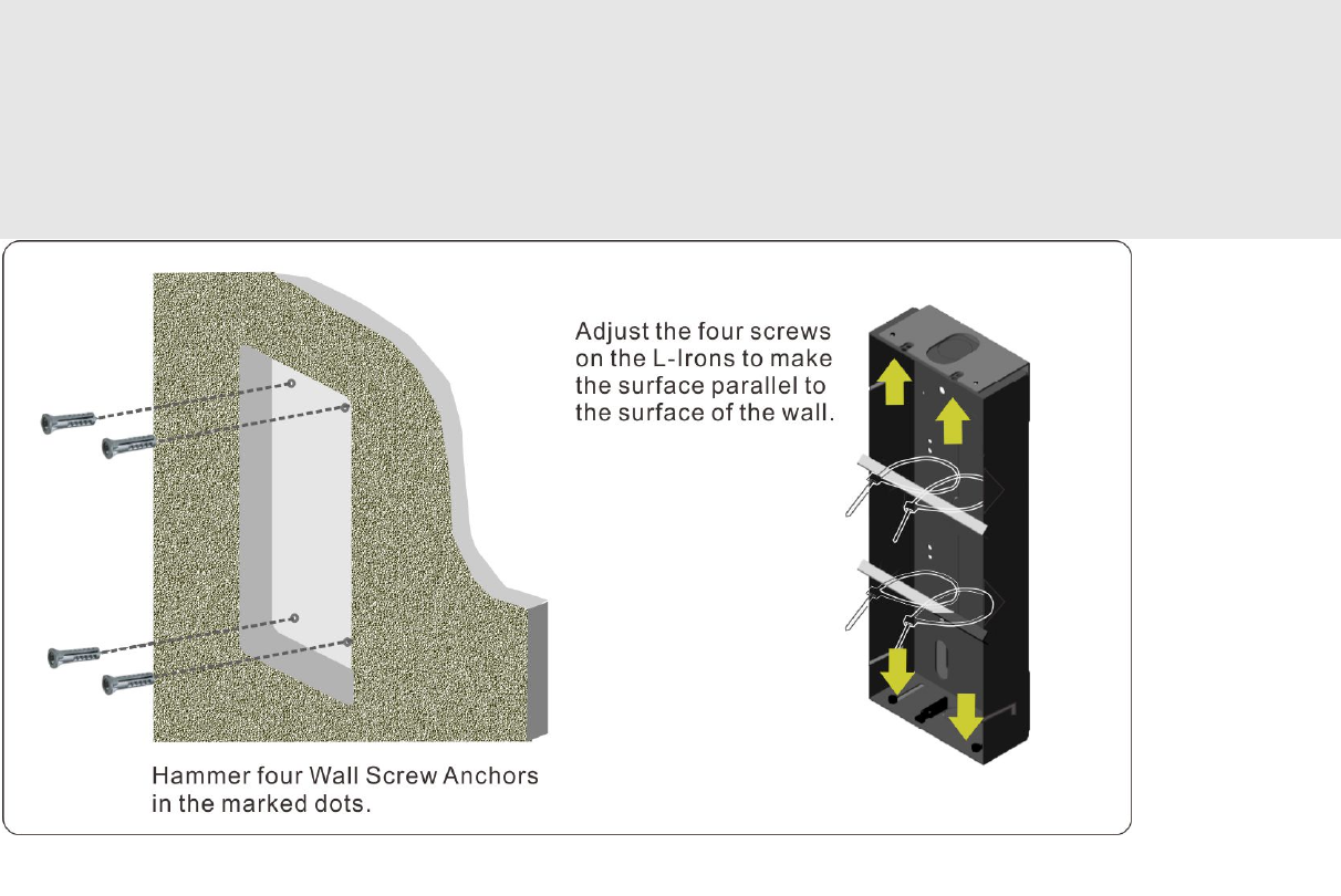
Step 3 Hammer four wall screw anchors into the drilled holes
(Refer to the figure on next page).
Step 4 Remove L-Iron from wall mounting box by loosing screws.
Step 5 Secure four screws and washers to secure the wall
mounting box and secure four screws on L-Irons.
Step 6 Tie four cable ties on the wall mounting box. (Refer to the
diagram on previous page).
Step 7 Again put wall mounting box into wall hole, secure wall
mounting box with L-Irons by securing four screws.
Step 8 Put Hang Rod in the cable ties, tie Hang Rods tightly on
Wall Mounting Box to keep wall mounting box parallel to
the surface of the wall.
Step 9 Again place a spirit level (bubble level) on the wall mounting box, Fasten L-Irons on the wall.
Step 10 Fasten screws to fasten wall mounting box with L-Irons.
Figure 12: Four Marks and Bubble Level
DP3010R VIDEO DOOR PHONE
17
Step 11 Remove Hang Rod and cable ties.
Step 12 Wire and cable connection
Step 13 Install DP3010R Main Unit
Step 14 Lock DP3010 on the wall.
Figure 13: Hammer Wall Screw Anchor and Move slightly the screws on the L-Irons to make the surfaces parallel.
MANUAL FOR SYSTEM INTEGRATOR
18
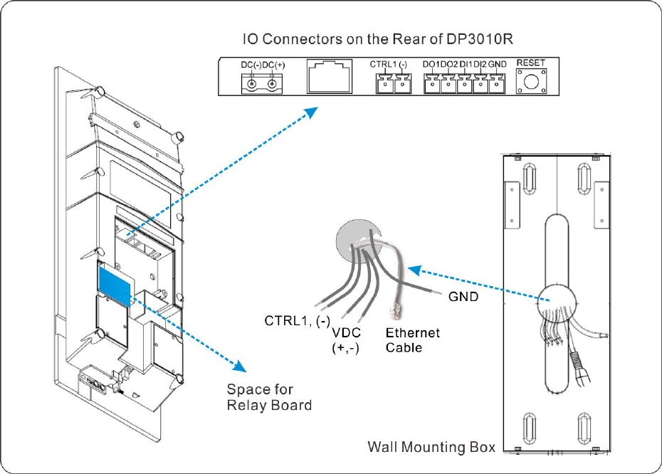
3. Wire and Cable Connection
In the center of the wall mounting box, wire and cable go through the wall and are mainly used for power, network connection,
and relay control. There are IO connectors on the rear side of the DP3010R. They are DC power, Ethernet port (RJ-45 connector),
and GPIO wire.
Figure 14: Wire and Cable from the wall
and going through the center of the Wall
Mounting Box
DP3010R VIDEO DOOR PHONE
19
Figure 15: IO Connectors on the Rear Side of the DP3010R
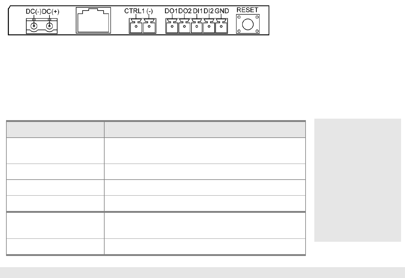
GPIO (General Purpose Input/Output) & Relay Control
The following table explains input and out put pins of GPIO and Relay Control.
Port definition Description
DI1 (Digital Input port 1) DI1 is used for is used for detecting whether the door is closed
or not. (Or, it is used for PIR.)
DI2 (Digital Input port 2) DI2 is used to connect to indoor “Open Door” button.
DO1 (Digital Output port 1) DO1 is used for external lighting.
DO2 (Digital Output port 2) (Reserved)
CTRL 1 Connect to CTRL 1 on Relay Board to control Electronic Door
Lock.
(-) (GND) Connect to GND
NOTE: 2. For more detailed information, please refer to Appendix A. IO Circuit Application.
NOTE: 1. Pressing RESET
button for about 6
seconds for the device
to restore to its original
factory default.
System will clear all RFID
log, Configuration, and
Number Entry Screen
data.
The network connection
mode of the device will
become DHCP mode.
MANUAL FOR SYSTEM INTEGRATOR
20
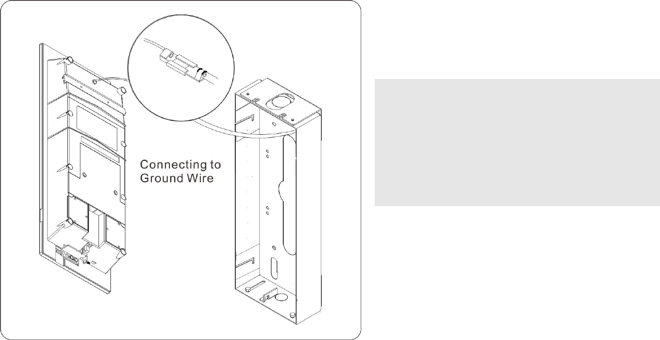
Connecting to Ground Wire
To prevent power surge and lighting strike from damaging DP3010R, wall mounting box should be connected to the ground wire
(earth wire) of the building. Connect the screw (for earth wire) of wall mounting box to ground wire of the building and fasten them.
NOTE:
To prevent power surge and lighting strike from
damaging DP3010R, wall mounting box should be
connected to the ground wire (earth wire) of the
building, and power switching in public area for
DP3010R should also be connected to the ground
wire (earth wire).
Figure 16: Connecting to Ground Wire
DP3010R VIDEO DOOR PHONE
21
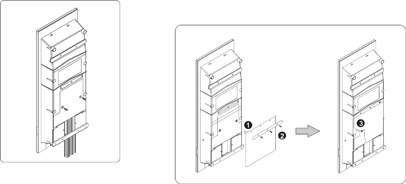
Fasten Rear Cover and Waterproof Mat
The following steps show how to install Waterproof
Mat:
1. Tear off adhesive tape on the upper end of the waterproof mat.
2. Fasten waterproof mat and bracket by screwing 3 screws.
3. Tear off adhesive tape on the center of the waterproof mat and attach adhesive side to rear cover smoothly.
After cable and wire connection are completed, Rear Cover needs to be put back and
fastened by screwing 2 screws.
Figure 17: Put Back Rear Cover
Figure 18: Install Waterproof Mat
MANUAL FOR SYSTEM INTEGRATOR
22
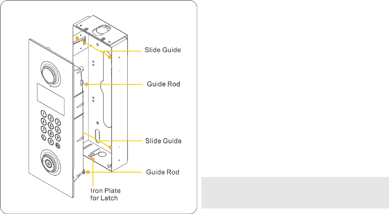
4. Installing DP3010R
Now DP3010R is ready to be installed on wall mounting box.
Please follow the steps below to install DP3010R onto wall
mounting box to complete installation.
1. Make sure that the latch on the rear side is at the right
position and would not bump into Iron Plate for Latch.
2. Carefully lift up the DP3010R Main Unit and align it to wall
mounting box.
3. Smoothly let upper Guide Rod and lower Guide Rod slide
into both Slide Guide and firmly push DP3010R Main Unit
toward the wall.
4. Push down DP3010R Main Unit and secure it on the wall.
NOTE: The protective cover on the DP3010R should not be removed
during DP3010R installation. Do not remove the protective cover
until new residents move in the house.
Figure 19: Install DP3010R Main Unit onto Wall Mounting Box
DP3010R VIDEO DOOR PHONE
23
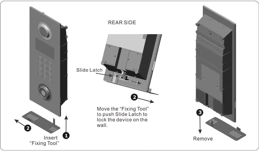
Lock DP3010R on the Wall
Please follow the steps
below to lock DP3010R
main unit onto wall
mounting box to
complete installation.
1. Use “Fixing Tool”
and insert it in the
gap between
DP3010R main unit
and wall mounting
box.
2. Move the “Fixing
Tool” to push Slide
Latch to lock the
DP3010R main unit
on wall mounting
box.
3. Remove “Fixing Tool”.
Figure 20: Install DP3010R Main Unit onto Wall Mounting Box
MANUAL FOR SYSTEM INTEGRATOR
24
DP3010R VIDEO DOOR PHONE
25
Chapter 4 : Uses of the Door Panel
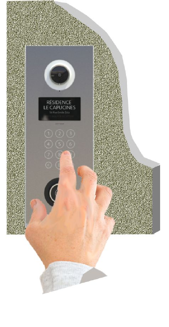
Access the Building or Community
A visitor can connect to a specific apartment by typing a part of the resident’s address. A visitor
can also directly connect with the security guard of the building by pressing the door bell button.
A resident can access the building or community by typing a password. (The password is
provided by the community management to each tenant). A resident can open door by scanning
an RFID card.
We conclude that there are 4 ways to access the building or community via DP3010R:
Connect an Apartment by Typing Resident’s Address
Connect the Security of the Building by pressing Door Bell Button
Enter Password to Open the Door
Scan a RFID card to Open the Door
Figure 21: Use of the Door Panel
MANUAL FOR SYSTEM INTEGRATOR
26
Basic and Important Operation
Figure 22: Basic and Important Operation of DP3010R
DP3010R VIDEO DOOR PHONE
27
System Boot
DESCRIPTION SCREEN
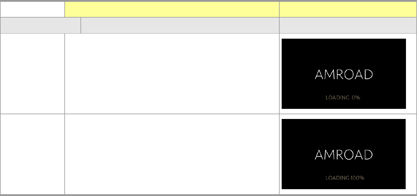
System Boot-Up
When system is being initialized, a percentage will be displayed for
the management staff and for explaining that system is running.
The time for System Boot-Up is around 40 seconds. When the
System Boot-Up is completed, “Home screen” appears.
0%->20%->40%->60%->80%->100%->Home Screen
MANUAL FOR SYSTEM INTEGRATOR
28
DESCRIPTION SCREEN
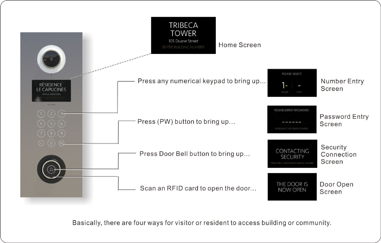
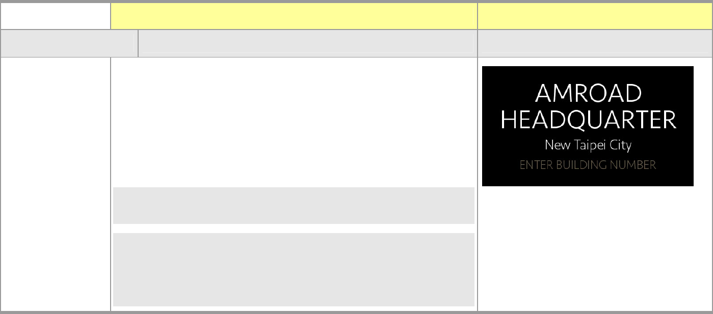
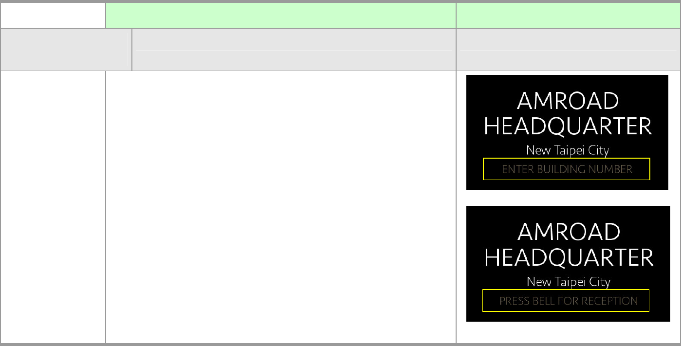
Home Screen
The Home Screen of the DP3010R may be the picture of your
community or text image.
The information block will display the text “ENTER BUILDING
NUMBER” and “PRESS BELL FOR RECEPTION” in turn on the lower
part of the Home Screen.
NOTE: 1. By default, the language is English. You can select English or
Traditional Chinese on Basic page of System unit in Chapter 5.
NOTE: 2. To upload your Home Page image onto DP3010R, you can
upload the image through WEB UI. (Please refer to Home Page
Image function on Config page of Upgrade Unit Configuration in
Ch5.)
Text Image
DP3010R VIDEO DOOR PHONE
29
LCD Screens for Visitor and Resident Operation
TABLE DESCRIPTION SCREEN
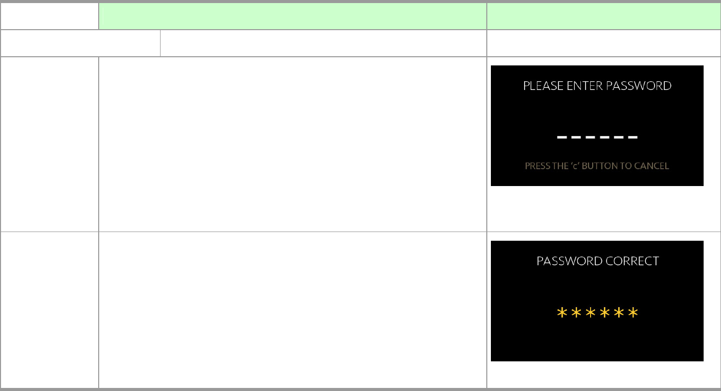
Password Entry Screen
Password
Entry Screen
On Home Screen, if the (PW) button is pressed, the Password Entry
Screen will appear for resident to enter his own password to open the
door.
NOTE 1: This Password function needs to work with Amroad ICMS
(Intelligent Community Management Server).
NOTE 2: Password Entering Screen can be Disabled or Enabled through
WEB UI.
Password Correct
If the user has input 6 digits correctly, when he presses the last correct
button the starts will become all yellow.
The system will open the door and present the Door Open Screen.
MANUAL FOR SYSTEM INTEGRATOR
30
TABLE DESCRIPTION SCREEN
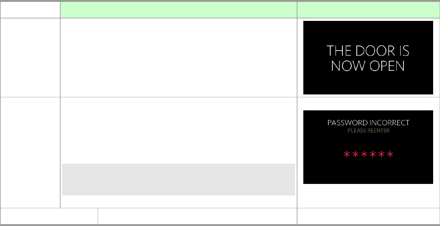
System will open Electronic Door Lock (open door), and “THE DOOR IS
NOW OPEN” is displayed on the Screen.
Password Incorrect
If the user has input 6 digits and one of them is not correct, when he
presses the last button the stars will become all red.
The screen will return to Password Entry Screen.
NOTE: While inputting password, you can press (C) button to delete
wrong digit that you have just input. Or press (PW) button to
delete all digits that you have input.
RFID Entry Screen
DP3010R VIDEO DOOR PHONE
31
TABLE DESCRIPTION SCREEN
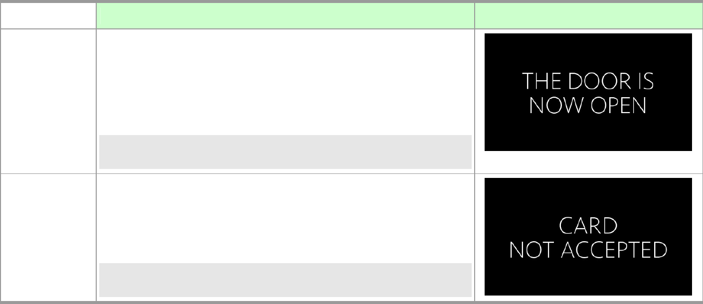
Card Accepted
Scan an authorized RFID card on SCANNING ZONE. If the system accepts
the card, the screen will appear “THE DOOR IS NOW OPEN” and the
system will open the door.
NOTE: There will be the sound of “Bi! Bi!” from speaker if the system
accepts the card.
Card Not Accepted
If the card is not accepted, the screen will appear “CARD NOT
ACCEPTED.”
NOTE: There will be the sound of “Bi! Bo!” from speaker if the system
does not accept the card.
MANUAL FOR SYSTEM INTEGRATOR
32
TABLE DESCRIPTION SCREEN
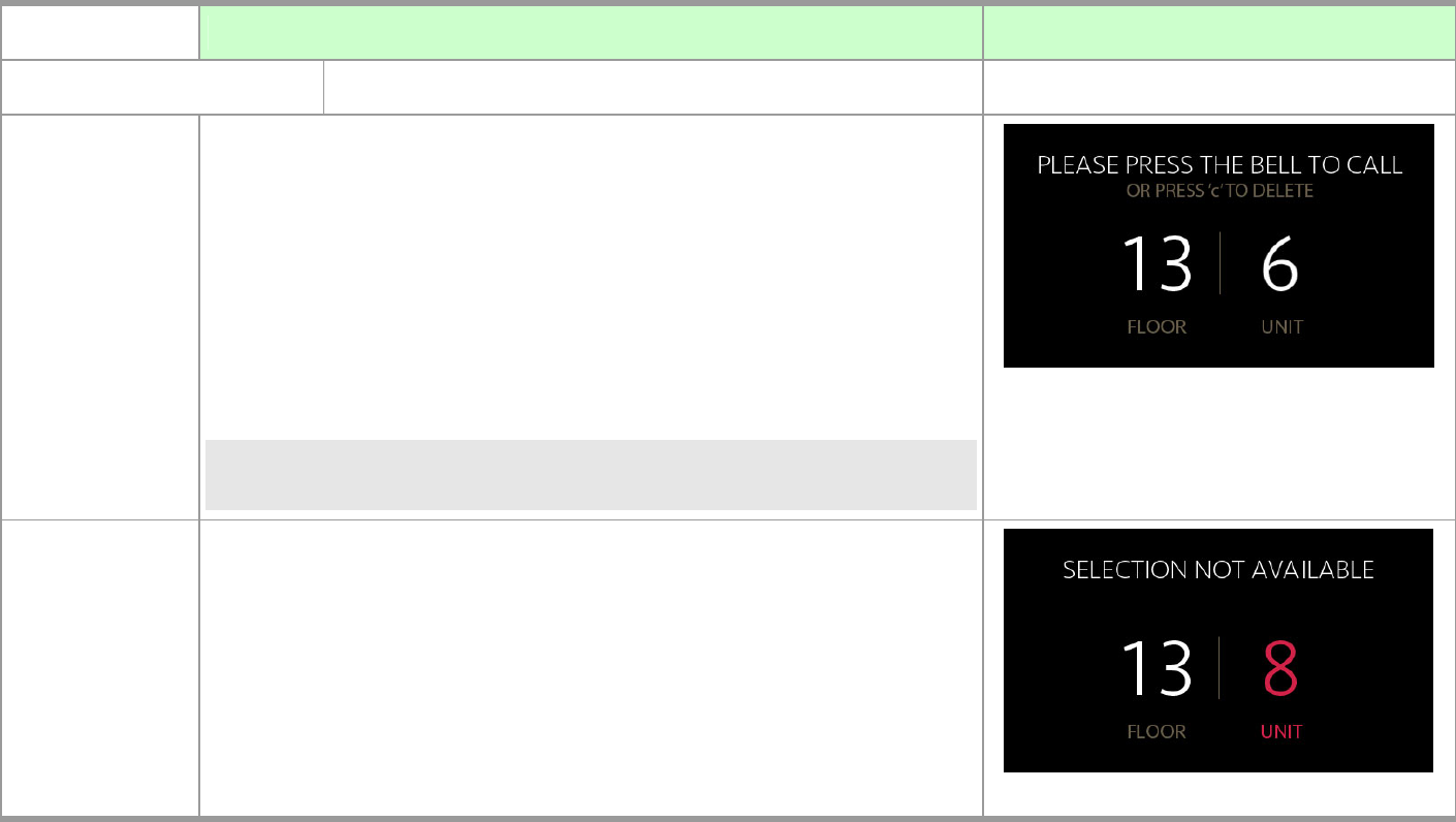
Number Entry Screen
1. Enter Address Number
On Home Screen, if any of the numerical keypads is pressed, the Number
Entry Screen will appear for visitors to enter address number to connect
a specific apartment.
“C” Button
Pressing the “C” button will delete the last entered digit in the field.
After deleting the last digit, the screen will return back to the Home
Screen.
NOTE: Press “C” button for 2 seconds to delete all digits that you have
inputs on the screen.
Error Notice (Not Available)
The number (digit) will become red number when you type in FLOOR or
UNIT number that does not exist in the building. And, System will
automatically delete the error digit.
DP3010R VIDEO DOOR PHONE
33
TABLE DESCRIPTION SCREEN
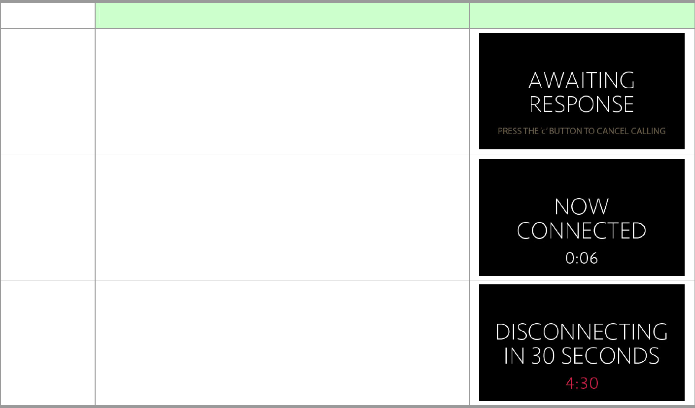
2. Pressing Door Bell
After completing address number, visitor can press Door Bell Button to
enter the address number to connect desired apartment.
Text “AWAITING RESPONSE” will be displayed on the screen. Please wait
for system to connect to your desired apartment.
3.Connection (on Conversation)
When the Video Door Phone DP3010R is connected, the screen shows as
right picture “Now Connected “.
The time will appear on screen for first 6 seconds, and the time
disappears until 4:30. It appears again.
Each conversation can last maximum 5 minutes (300 seconds).
After 4:30, the LCD screen will prompt user “DISCONNECTING IN 30
SECONDS”. The talking time will be ended within 30 seconds.
MANUAL FOR SYSTEM INTEGRATOR
34
TABLE DESCRIPTION SCREEN
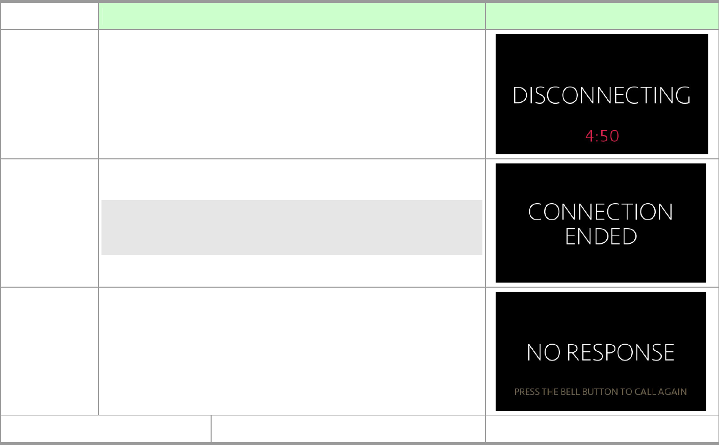
At 4:50, the conversation (Connection) is going to be ended.
4.Connection Ended
NOTE: While DP3010R is connected, you can press “#” button on you IP
Video phone/Video Indoor Station to open door. “THE DOOR IS
NOW OPENED” screen will be displayed.
Nobody Answers Phone Call
If nobody answers the phone call after a period of time, “NO RESPONSE”
screen will be displayed. You may press Door Bell button again to call
again. For the second time nobody answers the phone call, the screen
will turn to Home Screen.
Security Connection Screen
DP3010R VIDEO DOOR PHONE
35
TABLE DESCRIPTION SCREEN
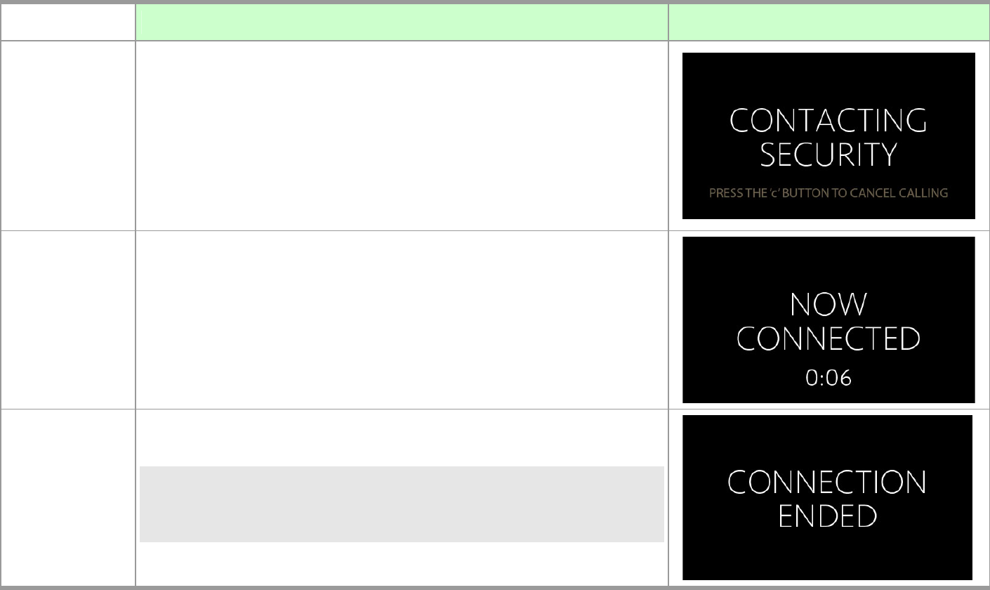
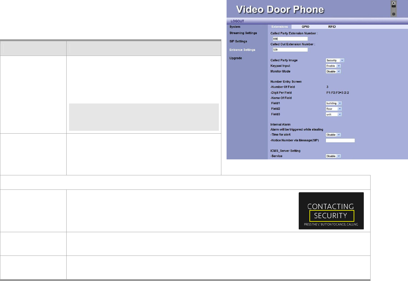
Pressing Door Bell Button
On Home Screen, if the Door Bell Button is pressed, the screen will
appear “CONTACTING SECURITY” and allow visitor(s) to directly connect
Security Management of the building (or the community).
Connection (on Conversation)
When the Video Door Phone DP3010R is connected, the screen shows as
right picture “Now Connected “.
The time will appear on screen for first 6 seconds, and the time
disappears until 4:30. It appears again.
Connection Ended
NOTE: While DP3010R is connected, you can press “#” button on you IP
Video phone/Video Indoor Station to open door. “THE DOOR IS
NOW OPENED” screen will be displayed.
MANUAL FOR SYSTEM INTEGRATOR
36
TABLE DESCRIPTION SCREEN
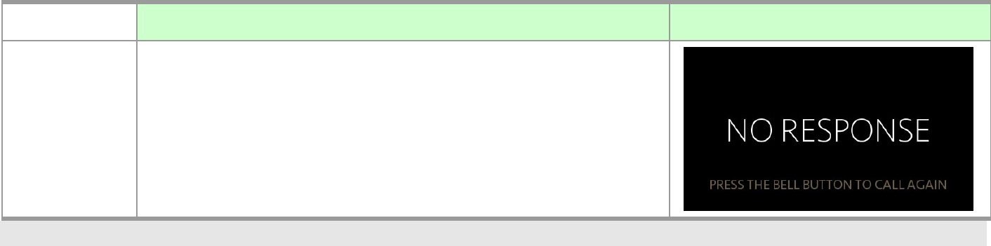
Nobody Answers Phone Call
If nobody answers the phone call after a period of time, “NO RESPONSE”
screen will be displayed. You may press Door Bell button again to call
again. For the second time nobody answers the phone call, the screen
will turn to Home Screen.
NOTE: Each conversation can last maximum 5 minutes (300 seconds).

DP3010R VIDEO DOOR PHONE
37
System Out OF ORDER
Out Of Order
The system will display different “Out Of Order” messages to help the
building management staff to identify the cause of the problem.
The message may includes:
Device Malfunction
Network Connection Has Been Lost
Error Retrieving IP Address
SIP Registration Failure
MANUAL FOR SYSTEM INTEGRATOR
38
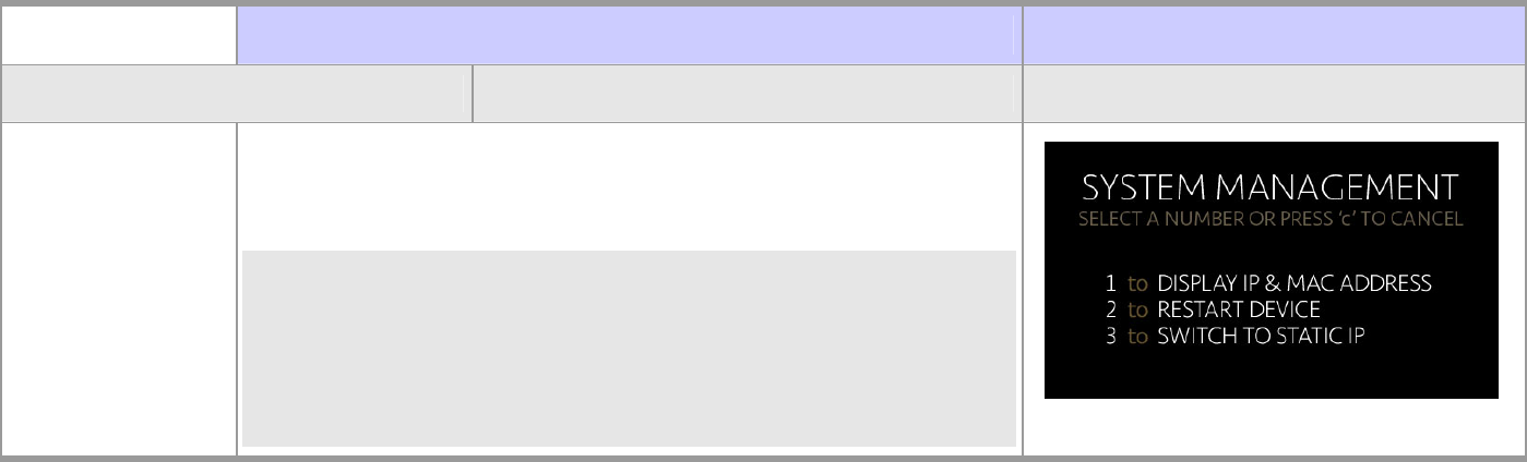
System Management Screens
To bring up System Management Screen, building management (or community management) press and hold (PW) button on
Home Screen for 10 seconds.
There are four functions included in the System Management Screen:
1. to Display IP & MAC Address
2. to Reset Device
3. to Switch to Static IP
4. Enable Alarm Sensor (Hidden Feature)
DESCRIPTION SCREEN
System Management Screen
To bring up System Management Screen, just press and hold (PW)
button for 10 seconds.
NOTE: 1. Press numerical keypad 1, 2, or 3 to bring up further
management screen. Or, you can press keypad 4 to enable
Alarm Sensor (Hidden feature without display screen.)
2. By default, Alarm Sensor is disabled. You need to enter
System Management Screen to enable it by pressing keypad 4.
DP3010R VIDEO DOOR PHONE
39
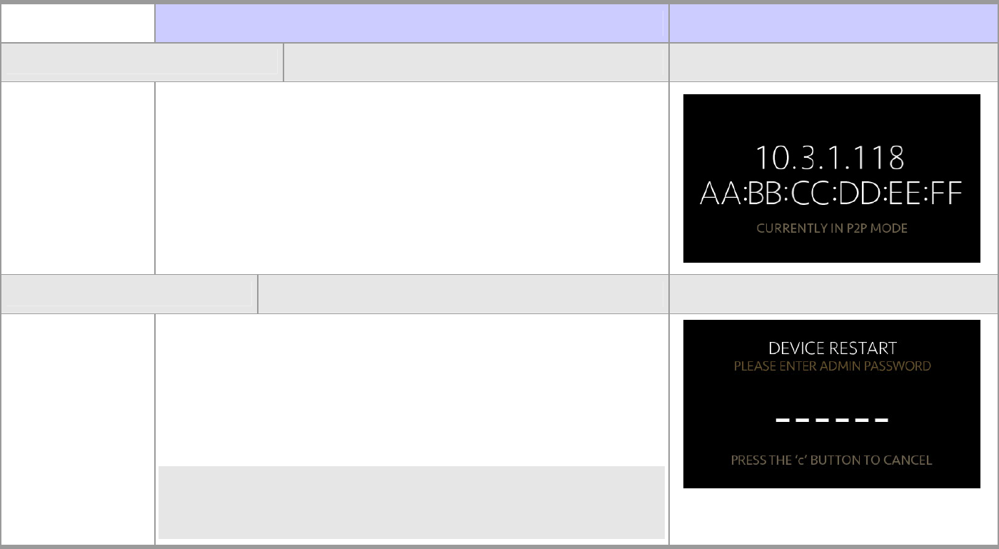
DESCRIPTION SCREEN
IP Address Display Screen
From System Management Screen, press numerical keypad 1 will
bring up Display IP Address screen.
Device Restart Screen
From System Management Screen, press numerical keypad 2 will
bring up Device Restart Password screen.
Enter 6-digital admin password to restart DP3010R or press (C)
button to exit.
NOTE: The default password is 123456.
You may change the password on Upgrade page of Upgrade
Unit in Ch5.
MANUAL FOR SYSTEM INTEGRATOR
40
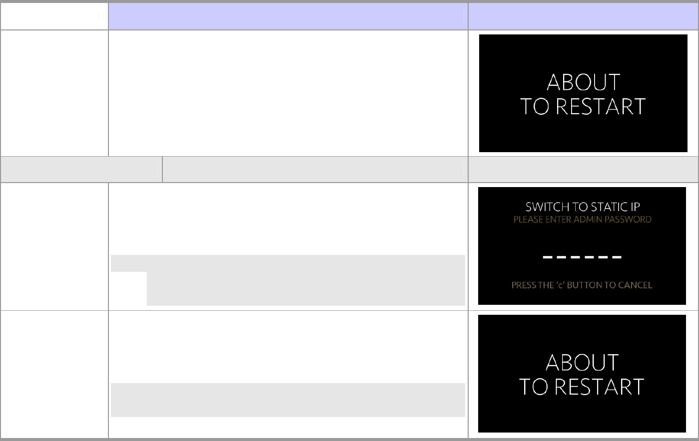
DESCRIPTION SCREEN
After you have entered 6-digital correct password. The system is
ready to reset DP3010R.
Switch to Static IP
From System Management Screen, press numerical keypad 3 will
bring up SWITCH TO STATIC IP Password screen.
Enter 6-digital admin password to switch to static IP (192.168.0.50)
or press (C) button to exit.
NOTE: The default password is 123456.
You may change the password on Upgrade page of Upgrade
Unit in Ch5.
After you have entered 6-digital correct password. This screen will be
displayed when system is ready to restart.
NOTE: After restarting the device, the Home screen remains the
same, but the IP address is changed to Static IP.
DP3010R VIDEO DOOR PHONE
41
Have Your Own Home Screen via Web UI
DESCRIPTION SCREEN
Format of Home
Screen
The Home Screen of the DP3010R may be the picture of your
community or text image.
To have your own Home Screen, please prepare an image in the size
of 480x272 pixels and format of JPG. (It is suggested that black
background would have better visual effect.) The name of the file
should be IMG_480x272_background.jpg.
To upload Home Page image onto DP3010R, you can upload the
image through WEB UI. (Please refer to Home Page Image function
on Config page of Configuration in Ch5.)
The information block will display the text “ENTER BUILDING
NUMBER” and “PRESS BELL FOR RECEPTION” in turn on the lower
part of the Home Screen with the size of 480x84 pixels.
MANUAL FOR SYSTEM INTEGRATOR
42
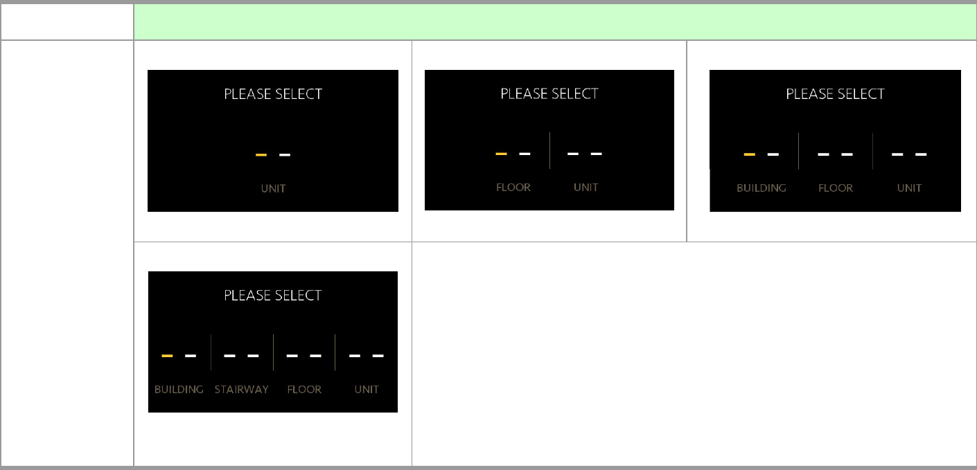
Number Entry Screen
4 Types of Number Entry Screen
Type 1. Single Field
(Max. 4 digits)
Type 2. Two Fields
(Max. 2 digits, 2 digits)
Type 3. Three Fields
(Max. 3 digits, 2 digits, 2 digits)
Type 4. Four Fields
(Max. 2 digits, 2 digits, 2 digits, 2 digits)
There are four types of Number Entry Screens (Number Entry Screen type is configured
through Web User Interface).
For more information on how to configure Number Entry Screen, please refer to
Sample item on Configuration page of Update unit in Chapter 5.
DP3010R VIDEO DOOR PHONE
43
DP3010R RFID Card Usage
Residents scan RFID card on the SCANNING ZONE. DP3010R will verify the database to determine whether to Open door or not.
Issue Master RFID Card First Time
Without any cabling, just scan RFID card on the DP3010R SCANNING ZONE when the DP3010R device 1st time on-line. The RFID card
will be used as Master Card1.
NOTE: 1. Before using Master RFID Card, you need to enable Add User Function by Master Card on RFID page of Entrance Setting unit
of WEB UI (User Interface) in CH5.
2. The Master Card is used for issuing new card,
and it can NOT be used for opening door.
If you scan another RFID card instead of Master Card
on DP3010R SCANNING ZONE for the first time, the
first-time scanned RFID card will become RFID
Master Card.
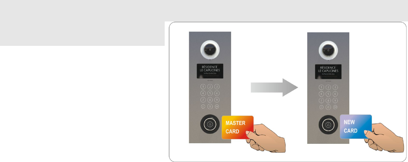
Issue a New Card with Master Card:
Scan Master Card on DP3010R First.
Within 10 seconds, scan new RFID card on DP3010R,
DP3010R will store new Card number Into Database.
The new RFID card is authorized and can be used to
scan on RFID SCANNING ZONE and open door. Figure 23: Issue a New RFID Card
MANUAL FOR SYSTEM INTEGRATOR
44
DP3010R VIDEO DOOR PHONE
45
Chapter 5 : Configuring Video Door Phone
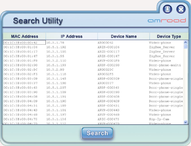
Finding Video Door Phone on Networks
The default connection type setting of the Video Door Phone is
“DHCP Client”, it is a typical network mode. There is a software
utility provided by your local distributor or local dealer which is able
to help you to find your Video Door Phone when using dynamic IP
address. Please execute following utility:
AmRoad Search Tool.exe
You will see a window pop up on screen. This utility will search whole
network segment automatically when utility is activated, then it will
show search results. You may press the “Search” button to search
again. The search result includes following elements:
MAC Address: This MAC is a unique number that provided by manufacturer.
IP Address: Here shows the IP address of found Devices (Video Door phone).
Device Name / Device Type: Here shows which type of devices are found. For example, you may find Video Door Phone/ IP
Video Phone in the same network.
Figure 24: Search Tool- Search Utility

MANUAL FOR SYSTEM INTEGRATOR
46
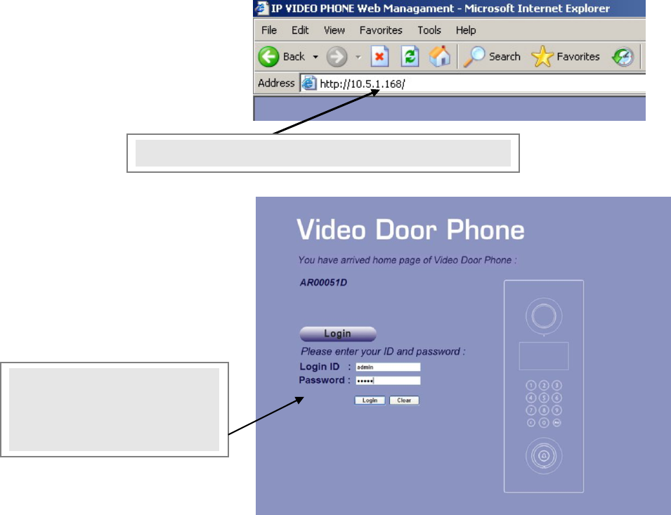
Entering Web User Interface
Input the IP address of this product on your browser, then you will see home page of the Video Door Phone appearing.
Web UI is protected by Login ID and Password. Press the “Login” button, then you will see input fields: Login ID and Password.
Please key in the correct ID and password, and then press second “Login” button to enter Web UI. The default ID and password are:
Login ID: admin
Password: admin
NOTE:1. While configuring WEB UI (User Interface), please do not operate this product so as to prevent this product being out of
order.
2. Do not input special symbols “, \, and & in the fields on the WEB UI. Otherwise, you will fail to save your setting
normally.
3. After configuring some Web pages and pressing “SAVE” button, you need to wait a little longer for system to save the
configuration.
DP3010R VIDEO DOOR PHONE
47
This chapter describes how to configure yourDP3010R with Web User
Interface. It contains advanced settings that may help you to solve
certain compatibility issues with your services. This UI also provide
remote management capability to service provider.
There are 5 units and total 13 pages:
System
Basic
Network
Login Name
Reboot
Streaming Settings
Video
Audio
SIP Settings
Entrance Settings
Extension
GPIO
RFID
Upgrade
Upgrade
Config
APS
2. The default ID and
password for system login
are “admin” and “admin”.
1. Input IP address of your DP3010R
Figure 25: IP address and Login
MANUAL FOR SYSTEM INTEGRATOR
48
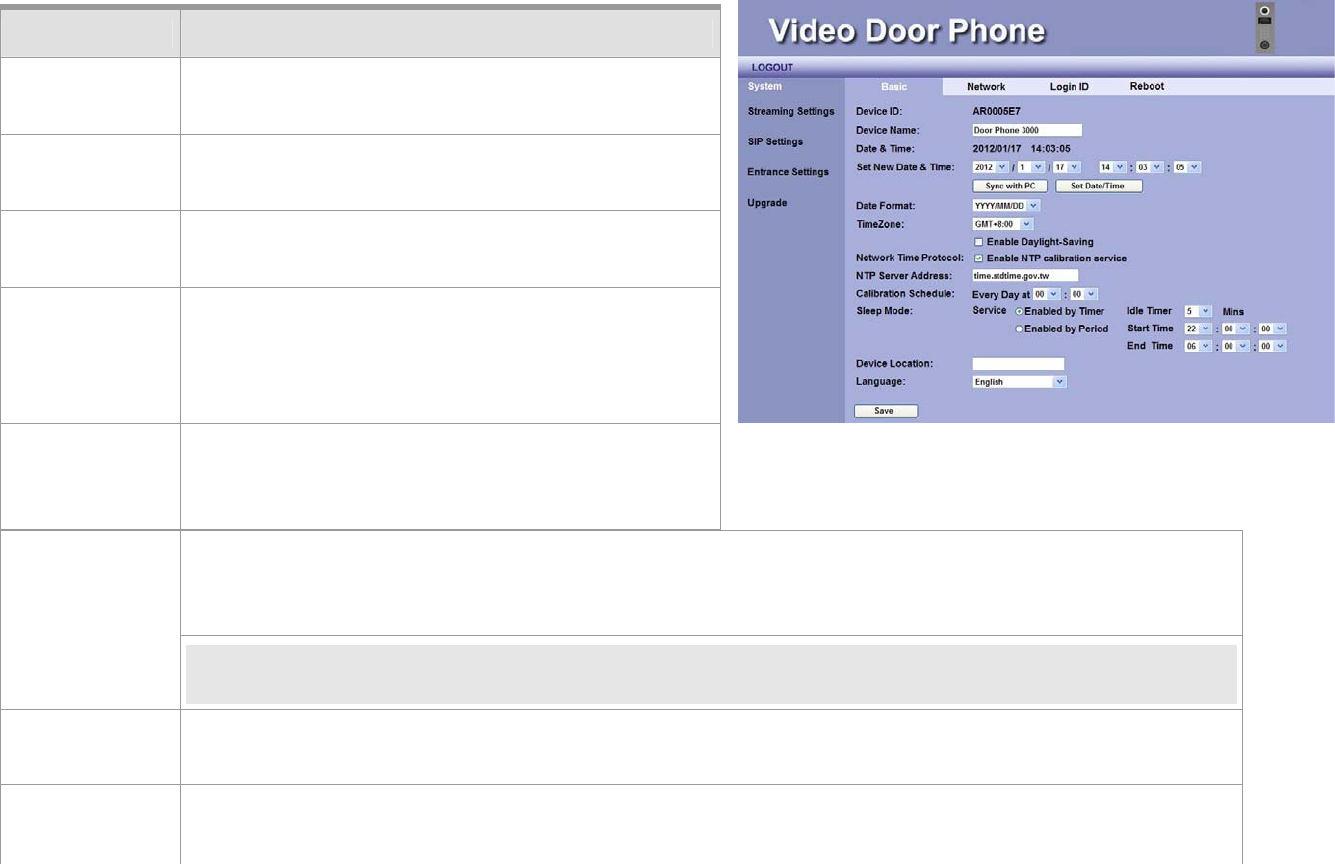
System - Basic Settings
This field allows you to select your time zone to fit your location. You can enable the Daylight-Saving
feature if needed.
Time Zone
NOTE: Daylight Saving Time is a way of getting more light out of the day by advancing clocks by one
hour during the summer.
Network Time
Protocol
Enable NTP Calibration service to allow the system to calibrate the time with NTP server through
Internet.
NTP Server
Address
You may use your preferred NTP server by input new address here.
Item Description
Device ID This ID is a unique number that assigned by
manufacturer.
Device Name The field allows user to give a specified name for
identification such as “Door Phone 3010R”.
Date & Time Here shows date and time set on this video door
phone.
Set New Time
and Date
These fields allow user to set correct date and time
according to the local–standard. You may
synchronize phone time to match your PC by
pressing “Sync with PC” button.
Date Format You can select preferred date format at this field.
There are 2 formats available: YYYY/MM/DD, and
MM/DD/YYYY.
Figure 26: System - Basic Settings
DP3010R VIDEO DOOR PHONE
49
Calibration
Schedule
You may select the time that you wish to do this NTP calibration.
Sleep Mode This feature lets you set the time period of lighting in order to save energy and protect your LCD
screen.
Service: Enabled by Timer or Enable by Period.
Enabled by Timer: You can select idle timer 5, 10, 30, 60 Mins.
Enabled by Period: Start Time: Select starting time of lighting.
End time: Select ending time of lighting.
NOTE: While setting Start Time and End Time, Start Time should be earlier than End Time.
Device
Location
The field allows user to give a device location for identification such as “East Building”.
Language Select the language “English” or “Traditional Chinese” to be displayed on your DP3010R LCD GUI.
NOTE: The language displayed on LCD Screen can be selected and changed by selecting “English” or
“Traditional Chinese”
Save Click this button to save your setting.
MANUAL FOR SYSTEM INTEGRATOR
50
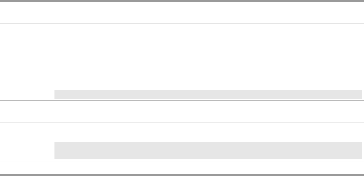
System – Network Settings
Item Description
MAC Address This is a quasi-unique identifier attached to most
network adapters.
IP Type
The default value is DHCP Client.
There are three options: DHCP Client, Static IP and PPPoE.
A. DHCP Client: The system will automatically
assign you an IP address.
B. PPPoE: This allows you to set Internet
connection with User Name and Password.
NOTE:For PPPoE connection mode, we suggest
that bandwidth-128kbps would have better
video quality.
C. Static IP: you have to input IP address, Subnet Mask, Default Gateway, Primary DNS and Secondary
DNS data.
DHCP VendorClassID will fill in “ARTE_VDPH”. (Engineering using).
Save Click this button to save your setting.
Figure 27: Network Settings
DP3010R VIDEO DOOR PHONE
51
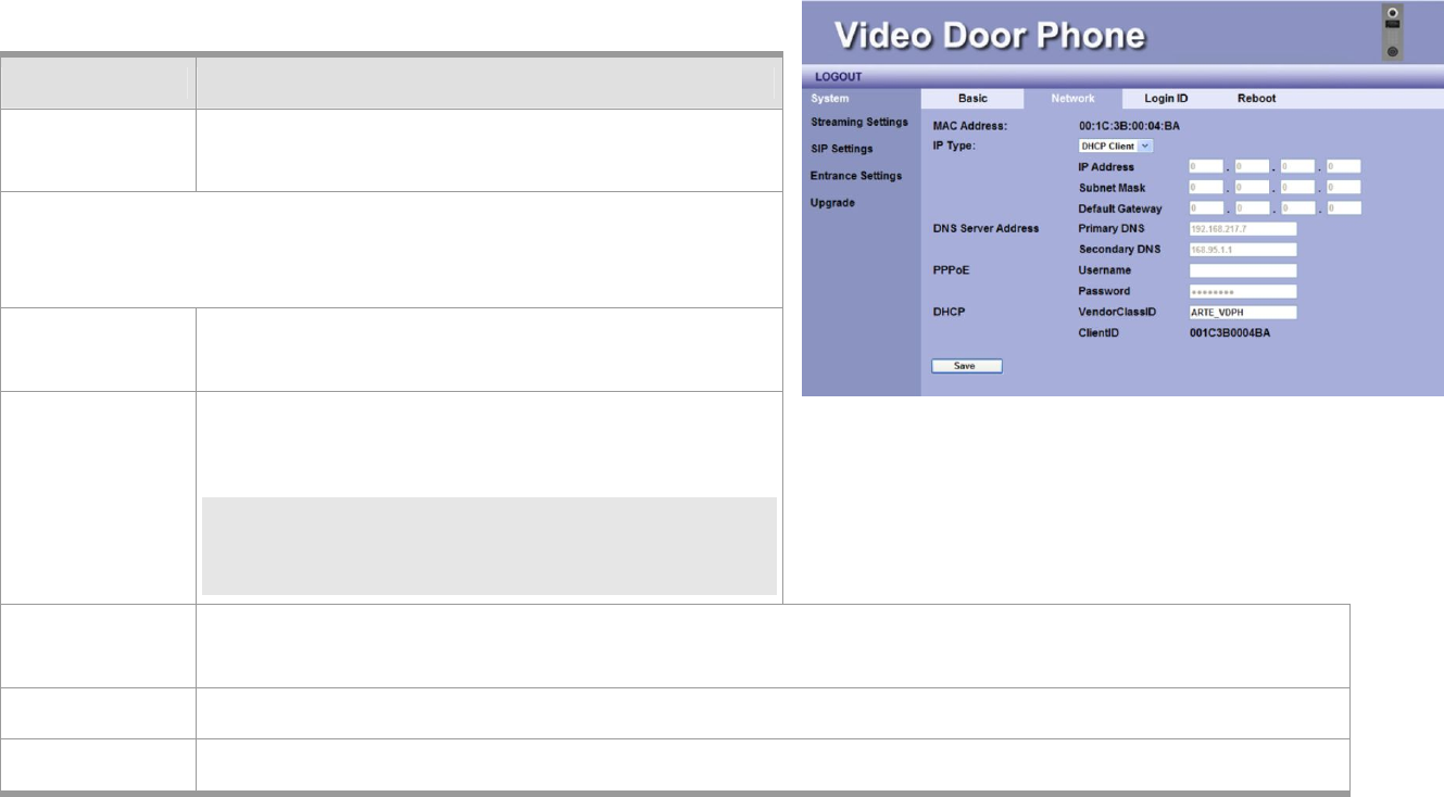
System - Login Name
System Login Name
The default ID and password for system login are admin and admin.
User may change his Login ID and Password on the webpage by entering
new Login ID and Password.
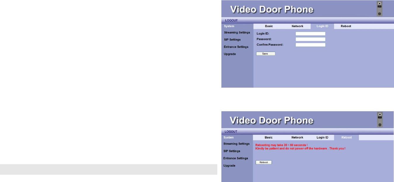
System Reboot
When user needs to reboot DP3010R remotely, just click “Reboot”
button on this webpage to start this action. After confirm rebooting,
Web User Interface will back to the home page, but the video door
phone may take 30~60 seconds to restart its system.
NOTE: DO NOT operate the DP3010R while system is rebooted (reset).
Figure 28: Login ID
Figure 29: Reboot
MANUAL FOR SYSTEM INTEGRATOR
52
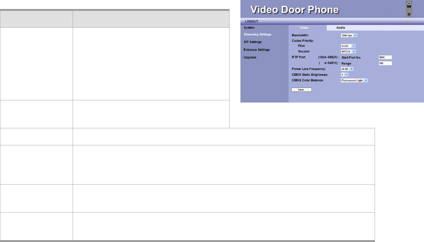
Streaming Settings – Video
You may set change the video settings in this page.
Item Description
Bandwidth You may select preferred bandwidth for video
and audio streaming. There are 4 options:
128Kbps, 256Kbps, 384Kbps, and 512Kbps.
Please check which bandwidth is suitable for
you with your service provider.
Default setting is 256Kbps.
Codec Priority– First – You may select the Video streaming
priority - H.263
Second –You may select the Video streaming priority - H.263, or Disable.
RTP Port This field allows you to set a range of port numbers for RTP ports. Start Port Number. Total
available ports are from 1024 to 65531. You may select a start port number.
The default value of Start Port Number is 9000.
You may select a start port number and set a range from that port. The range is between 4
and 64511. The default value of range is 100.
Power Line
Frequency
You may select the power frequency according to your local power specifications. Wrong
power frequency may cause the video flicking abnormally. Default setting is 60Hz.
Figure 30: Video Setting
DP3010R VIDEO DOOR PHONE
53
NOTE: If DP3010R can’t get the correct value of the CMOS brightness in some environment, please adjust the brightness value
via the Videophone by pressing “2”(brighter) or “8”(darker) in conversation state, or pressing “5” to turn on/off WL LED
by yourself.
CMOS Static
Brightness
This item allows you to adjust the brightness of CMOS according to the lighting environment
of the installed location. Higher value makes the video brighter.
CMOS Color
Balance
This item allows you to adjust the color of video. Select according to the lighting
environment: Fluorescent Light, Yellow Lamps and Orange Lamps.
NOTE:
Fluorescent Light – This condition is suited for white lighting environment.
Yellow Lamps – This condition is suited for indoor yellow bulb environment.
Orange Lamps – This condition is suited for indoor orange color or more red color
environments.
Save Click this button to save your setting.
MANUAL FOR SYSTEM INTEGRATOR
54
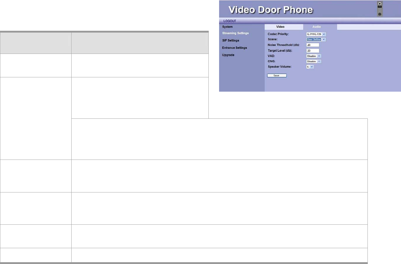
Streaming Settings – Audio
ITEM Description
Code Priority You may select the Audio streaming
priority – G.711.
Select Disable, Enable or User Define.
When “User Define” is selected, the
following two items appears:
Scene
Noise Threshold (db): Default: -40. The voice intensity that is lower than the value (-40db)
will be neglected. (Acceptable value -40~-52)
Target Level (db): Default: -23 The voice intensity that is around normal intensity will
be processed to be the value (-23db). (Acceptable value -20~-32)
VAD You may enable or disable Voice-Active-Detection function here. The DP3010R will detect
background noise and send silence packet to the other end if this feature is enabled. This
allows called party to hear better audio quality.
CNG You may enable or disable Comfortable-Noise-Generate function here. The DP3010R will
generate background noise when receiving silence packet from the other end if this feature is
enabled. This allows called party to hear better audio quality.
Speaker
Volume
This item allows you to select volume of speaker. There are 10 levels, 0 ~ 9.
Save Click this button to save your setting.
Figure 31: Audio Setting
DP3010R VIDEO DOOR PHONE
55
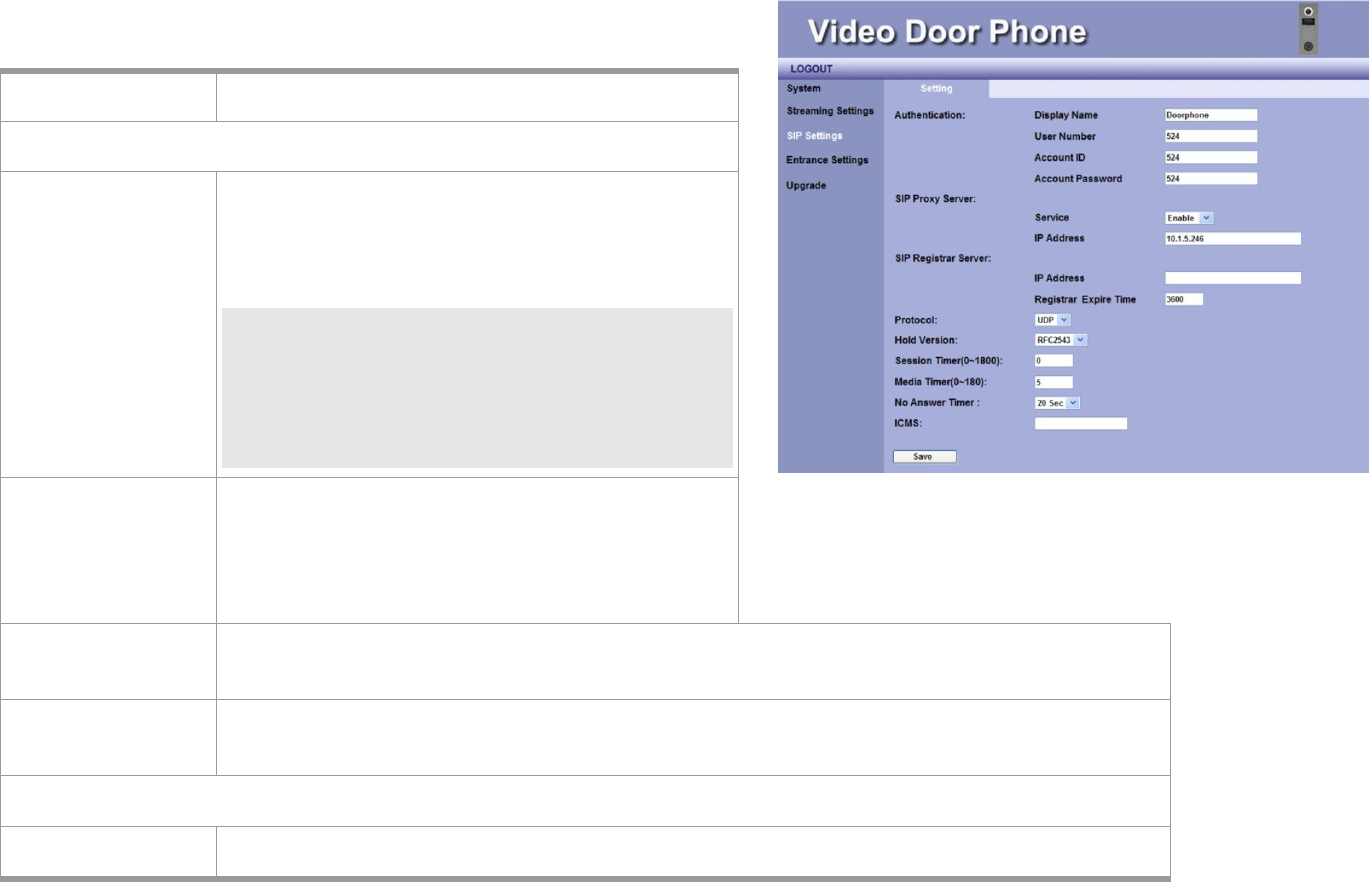
SIP Settings
You may setup advanced SIP service parameters in this page:
Item Description
Authentication
Display Name This name will show on the IP phones of called
parties. You can fill in the preferred name here.
For example, Doorphone
NOTE: Please enter Doorphone in the field of
Display Name. When Door Bell is
pressed, there will be “Preview” function
and “Ding-Dong” sound on Amroad IP
Video Phone/Video Indoor Station.
User Number You may fill in the phone number here, normally
it is provided by service provider. To work with IP
PBX, you may fill in extension number.
For example, 524
Account ID You may fill in your account name of SIP service in this field. For example, 524
Account Password You may fill in the password of your SIP service account. For example, 524
SIP Proxy Server
Service You may select “Enable” or “Disable” the SIP Proxy Server in the dropdown menu.
Figure 32: SIP Settings

MANUAL FOR SYSTEM INTEGRATOR
56
NOTE: For Peer-to-Peer mode, both devices (DP3010R and remote device) need to select
Disable in the dropdown menu. And, fill in each other’s IP address.
IP Address You may fill in the IP address of SIP Proxy Server in this field.
NOTE: For Peer-to-Peer mode, user needs to input IP address of the Remote device.
SIP Registrar Server
ITEM Description
IP Address You may fill in the IP address of SIP Registrar Server here.
Registration
Expire Time
Set the time for SIP registration authorization
The default is 3600 seconds.
Protocol You may select network communication protocol of the SIP service here. There are 2
options: UDP and TCP.
NOTE: Default setting is UDP protocol.
Session Timer
(0~1800)
You can set the session timer here. The range is from 0 to 1800 seconds.
Default is 0 second.
Media Timer
(0~180)
This setting allows your video door phone to force release automatically a conversational
call when your phone doesn't receive any media packets from the remote side during a
period of time.
NOTE: If you want to disable this feature, please fill in "0" sec.
No Answer Timer When visitor presses the door bell and no one answer the call, the DP3010R will wait for a
time period before “No Response” screen is displayed. You may select the time period-
20sec, 30sec, 45sec, or 60sec. Default is 20 seconds.

DP3010R VIDEO DOOR PHONE
57
NOTE: 1. The setting should be based on your IP PBX.
ICMS Input the IP address of ICMS. This function is customized and it allows DP3010R to send
pictures of visitors to ICMS.
Save Click this button to save your setting.
MANUAL FOR SYSTEM INTEGRATOR
58
Entrance Settings – Extensions
You may configure call services in this page:
ITEM DESCRIPTION
Called Party
Extension
Number
Fill in the extension number. When Door Bell
button is pressed, the device will dial to the
extension number. (The extension number or
group that is assigned by IP PBX.)
NOTE: In the Peer-to-Peer mode, you need fill
in the complete extension number and
IP address. e.g. 102@10.3.1.128
Called Out
Extension
Number
Fill in the extension number. When ALARM is
occurred, the device will dial to the called party
extension number. (The extension number or
group that is assigned by IP PBX.)
Called Party
Image
There are three options: Security, Reception, and Concierge.
The selected item will be displayed on the LED screen when the door
bell is pressed. The default is Security.
Keypad Input This item allows you to enable/disable Keypad Input Function by selecting Enable/Disable in
the drop-down menu.
Monitor Mode Select Enable/Disable Monitor Mode.
If Monitor Mode is enabled, resident can dial the extension number of the DP3010R to view
Figure 33: Extensions

DP3010R VIDEO DOOR PHONE
59
live outdoor video without changing LCD screen.
Number Entry Screen
Number Of Field This field shows the number of fields (columns) on DP3010R LCD Number Entry Screen.
Digit Per Field It displays the number of digits on each field (column) on DP3010R LCD Number Entry
Screen.
Name Of Field These allow you to select the name (Building, Stairway, Floor, or Unit) for individual Field
1~4. The result will be shown on DP3010R LCD Number Entry Screen.
Internal Alarm
Alarm will be
triggered while
stealing
This is a “Burglarproof” function.
Please disable this function when the device is not ready or during the device is repaired.
Time for Alert You can enable or disable the function of “Alarm will be triggered while stealing”.
Select Disable/3 Min/Always for the time period of alarm sound when the alarm is
triggered.
Notice Number via
Message (SIP)
You may fill in the Video phone number here. The device will inform the Video Phone when
the internal alarm is triggered.
ICMS_ Server Setting
Amroad ICMS (Intelligent Community Management Server)
Service You can enable or disable the function of ICMS_ Server Setting.
Notice ICMS IP Enter the IP address of ICMS Server.
ICMS will receive the message when Internal Alarm is triggered.
Notice ICMS Port Enter the port number of ICMS Server. The default Port Number is 7778.
ICMS will receive the message when Internal Alarm is triggered.

MANUAL FOR SYSTEM INTEGRATOR
60
Email Setting
DP3010R will take a picture after someone entering password, scanning RFID card, or nobody answering the Video
Door Phone DP3010R. You can disable or enable the following three items for system to send email with picture.
Trigger By Password After someone enters password, DP3010R will take a picture.
You can enable/disable the function for system to send email with picture.
Trigger By RFID After someone scans RFID card, DP3010R will take a picture.
You can enable/disable the function for system to send email with picture.
Trigger By No Answer Nobody answers the DP3010R for a specific time period, DP3010R will take a picture.
You can enable/disable the function for system to send email with picture.
System sending Email needs the related SMTP setting. SMTP is a relatively simple, text-based protocol. Input the
valid account number and password for the SMTP.
SMTP server Host name or IP address of the SMTP server for notification. e.g. smtp.gmail.com
SMTP port To specify the port of the SMTP server. If the field is empty, the default value is 25. The
“smtp.gmail.com” port is 587.
SMTP server Account Input SMTP server Account.
NOTE: Just enter the local-part of the email address (ex, John123), and you don’t need to
enter the domain name (ex, @gmail.com)
SMTP server
Password
Input SMTP server Password.
TLS Set enable/disable for mail transmission that “Confirms Client to the Server identity”
action is needed or not. TLS (Transport Layer Security) is a network protocol that ensures

DP3010R VIDEO DOOR PHONE
61
privacy between email servers on communicating applications.
Mail To Input e-mail address which you want to send to.
Save Click this button to save your setting.
MANUAL FOR SYSTEM INTEGRATOR
62
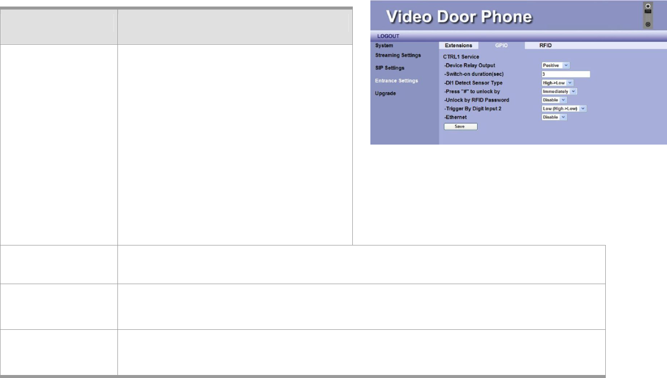
Entrance Settings – GPIO
You may configure GPIO in this page:
ITEM Description
CTRL 1 Service CTRL 1 Service is used to control the CTRL 1
of Relay Board, and then connects to
“Electronic Door Lock”.
The function can be triggered by the
following ways.
A. Using Registered RFID Card
B. During conversation, you may press “#”
keypad to open door.
C. Press the button that connects to “Digit
Input 2(DI2)” (Also refer to the description
below)
Device Relay
Output
You can select Positive/Negative to connect to Positive/Negative- triggered Electronic Door
Lock.
Switch-on duration
(sec)
This item lets you set the time (seconds) for Relay Board (DO2) to open “Electronic Door
Lock”. The default is 3 seconds.
DI1 Detect Sensor
Type
There are two options: “High->Low”, and “Low->High”.
You can select the voltage polar of digital input “High->Low” or “Low->High” for triggering.
Figure 34: GPIO
DP3010R VIDEO DOOR PHONE
63
Press “#” to unlock
by
You can select the timer “Immediately”, ”One Second”, or ”Two Second”.
Press the “#” key from IP Video Phone/Video Indoor Station to open “Electronic Door Lock”
during answering the call.
Unlock by RFID
Password
There are two options:
Disable: Disable the function of using RFID Password to open Electronic Door Lock.
RFID Password: Enter RFID password to open “Electronic Door Lock”.
Trigger By Digit
Input 2
You can set the “Digit Input 2(DI2)” as a trigger point. You may select the voltage polar “Low
(High->Low)”to “High (Low->High), or “Disable” for triggering.
NOTE: The DI2 (Digit Input 2) is used to connect Door Open Button.
It depends on the types (open, short circuit) of Door Open Button to select “Low
(High->Low)”or “High (Low->High).
Ethernet Some trusted Ethernets can be set up as a trigger point. Please contact with the provider
when you need more information. Or, you may disable this function.
Save Click this button to save your setting.
NOTE: Be careful with the wires connection of GPIO, especially the default polar voltage of hardware (digit output pins) is
high. Please select and set the related Electronic circuit to meet the hardware initial voltage.
MANUAL FOR SYSTEM INTEGRATOR
64
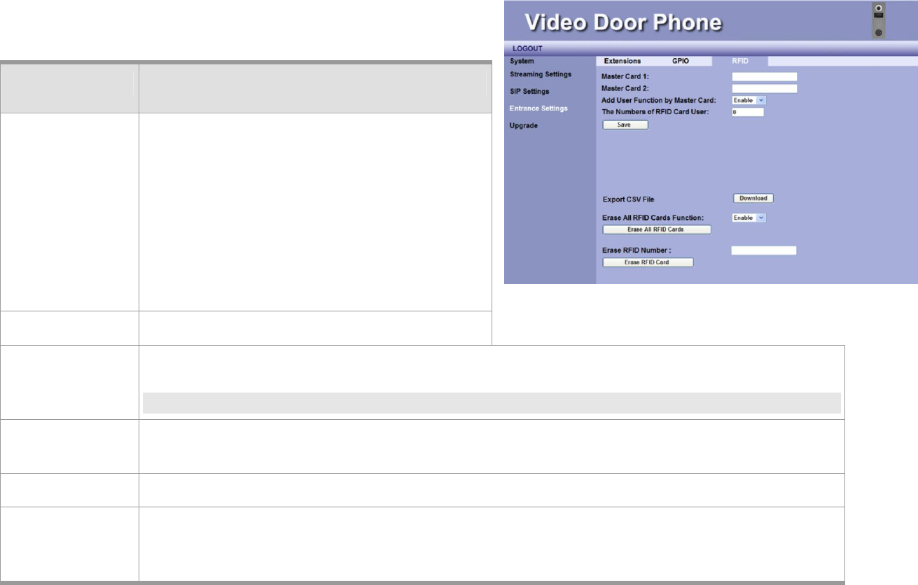
Entrance Settings –RFID
You can get the related RFID information and delete the issued RFID
Cards here.
ITEM DESCRIPTION
Master Card1 This field will display the card number of the
Master Card. By default, this field is null.
This master card can issue new cards for the
new tenants.
By factory default, this field is null, you can
scan a new RFID Card, and it can be set as
Master Card.
Master Card2 (Reserved)
Adds User
Function by
Master Card
This item is to select Enable/Disable the master card for issuing new tenants.
NOTE: If “Disable” is selected, user is unable to issue new card.
The Numbers of
RFID Card User
This field is used to display the number of RFID cards is issued currently.
Save Click this button to save your setting.
Export CSV File Click Download button to export CSV file to open or save the file Card_No.csv on your
computer. All issued RFID cards from this Video Door Phone will be listed in the CSV file.
Figure 35: RFID

DP3010R VIDEO DOOR PHONE
65
Erase ALL RFID
Cards Function
This item is used to delete all RFID Card numbers.
When “Enable” is selected, it allows user to erase all RFID card numbers or specific RFID card
number. Press Erase ALL RFID Cards to delete all RFID Card numbers.
Erase RFID
Number
You can input the specific issued RFID card number in the field and press Erase RFID Card to
delete it.
NOTE: The method for issuing new cards:
A brand new card can be issued by scanning following the Master Card1 scanning during valid timer (10 seconds).
MANUAL FOR SYSTEM INTEGRATOR
66
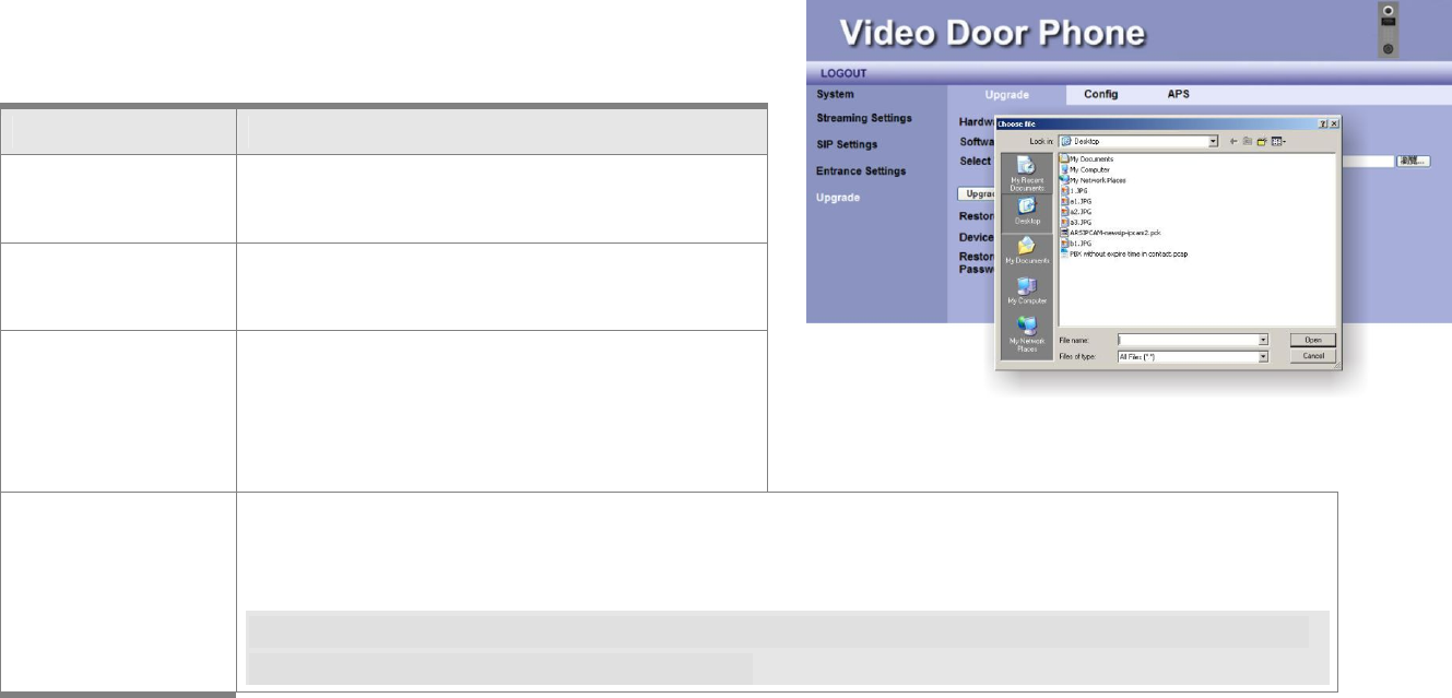
Upgrade –Upgrade
This section allows you to upgrade firmware of DP3010R through
network.
ITEM DESCRIPTION
Hardware Version This field shows hardware version number.
Software Version This field shows current firmware version
number.
Select Target File You may press Browser button to pop up a
File dialog box to select the location of the
new firmware that you wish to upgrade.
Upgrade After select the new firmware, you can press Upgrade button to start the upgrading. You will see
progress bar showing the upgrade status.
WARNING: DO NOT turn off or disconnect the Ethernet cable during upgrade, for it may cause
serious damage to this device.
Figure 36: Upgrade

DP3010R VIDEO DOOR PHONE
67
Restore Factory
Default
Press the Restore Default button and wait for system to restore its original factory default
setting.
NOTE: If DP3010R restores to its original factory default setting, you will lose previous setting,
Number Entry Screen (CSV File) data and RFID log, etc.
But the Home Page Image will remain.
Device Res tart
Password
This field is used to set password protection for DP3010R Device Reset.
Default Password is 123456.
Switch to Static
IP Password
This field is used to set password protection for device switching to Static IP
(192.168.0.50). Default Password is 123456.
MANUAL FOR SYSTEM INTEGRATOR
68
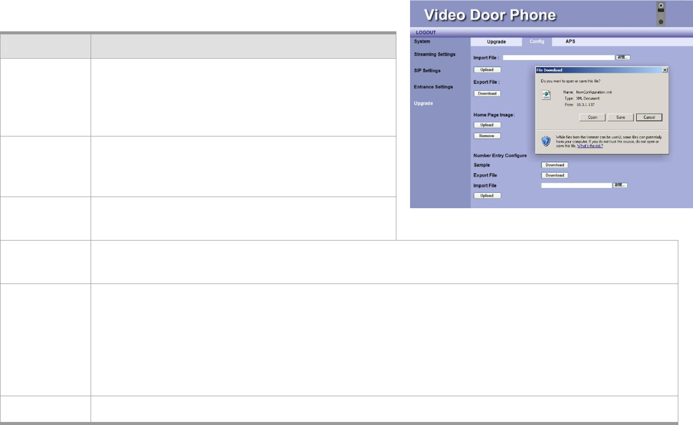
Configurations
Item Description
Import File User may press Browse button to select the location of
the configuration file to import, which you may
previously save to a local directory through the Export
File option.
Upload After selecting the configuration file, you can press
Upload button to start the importing.
Export File You can also use Export File to back up DP3010R settings
on your computer.
Download Press Download button to export, and you are prompted to click “Open” or “Save” for NewConfiguration.xml.
If you click Save, the configuration file will be saved into a local directory.
Home Page
Image
This item is used to upload your DP3010R LCD Home Page Image.
To upload image for LCD Home Screen, please prepare the image in the size of 480x272 pixels and format of
JPG. And, the name of the file should be IMG_480x272_background.jpg.
And, the file size should be less than 100KB.
Upload After selecting the LCD Home Page Image file, you can press Upload button to start the importing.
Figure 37: Configuration
DP3010R VIDEO DOOR PHONE
69
Remove Press Remove button to delete the image.
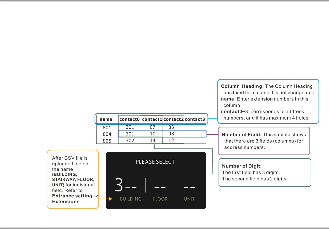
Number Entry Configure
Sample
The Sample allows you to download an example file of four Number Entry Screens including one, two, three,
and four columns address number.
Before you download the sample for reference, let us introduce the CSV format for our Number Entry
Configuration.

MANUAL FOR SYSTEM INTEGRATOR
70
Press Download to open or save the file. The downloaded file illustrates the examples of establishing address
number in one/two/three/four columns in the format of CSV.
Establish all address numbers into the CSV file and import the file from the Import field.
NOTE: You may use Microsoft Office Excel (*.xls) to establish the file and saved as *.csv efficiently. Then, we
suggest that you use WordPad (text editor) to modify the content. For example, “37, 7, 12,” should be
modified as “37, 07, 12,”, and save the CSV file.
Export File Press Download button to export current LCD Number Entry Configuration file to your computer.
The file name of the exported file is contact.csv.
Import File Press Upload button to import your Number Entry Configuration file for LCD Number Entry Screen.
NOTE: If you use Notepad to edit the contact.csv file and find it fails to upload, please use WordPad to edit
the file, save it as contact..csv, and upload it.
DP3010R VIDEO DOOR PHONE
71
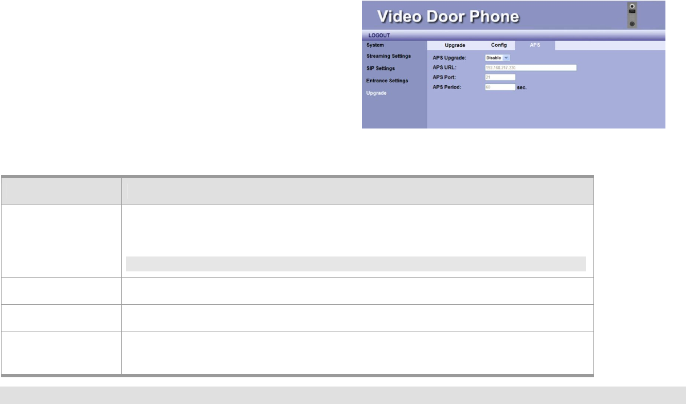
APS
This webpage allows manufacturing factory to perform
management function through APS (Auto Provision Server).
Item Description
APS Upgrade Allow user to Enable/Disable the function.
APS: Auto-Provision Server.
NOTE: The configuration is executed by manufacturing factory.
APS URL IP address of APS server
APS Port A port number that the phone uses to interact with APS server. Default is 21.
APS Period A length of time that the DP3010R sends the upgrade request to APS server periodically.
Default is 60 sec.
NOTE: It is suggested that only professional personnel is allowed to configure this webpage.
Figure 38: APS
MANUAL FOR SYSTEM INTEGRATOR
72
Functions Performed by the IP-PBX (Compatible with Amroad IP-PBX)
Simultaneous Ring –The Distribution Policy is set to Ring All. e.g. When a visitor calls the group call (say extension 500), group
members (say extensions 155, 157, and 166) will all ring simultaneously.
Call Forwarding – Enter a number to which incoming calls are forwarded
when unanswered. The number could be an extension or a PSTN number
with appropriate outbound prefix.
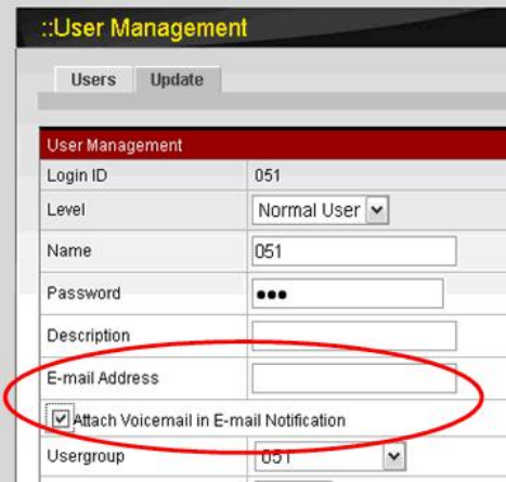
E-Mail/Voicemail Notification – IP PBX has a built-in voice mail subsystem
with a sophisticated IVR menu. A call to an extension unanswered could be
configured to enter voice mail recording procedure. After leaving a message,
a notification e-mail will be sent to the user owns the extension with or
without the message in the form of an attached WAV file.
Figure 39: Voicemail Notification Setting
DP3010R VIDEO DOOR PHONE
73
DP3010R VIDEO DOOR PHONE
75
Appendix A : Application
Electronic Lock
The DP3010R can connect with various Electronic locks, including Electronic Strikes, Electronic Bolts and Electromagnetic locks.
Wiring Connection and Web Page Setup
There are two types of Electronic door lock
applications as below. One is Electronic Bolt,
and the other is Electronic Strike. For more
Electronic locks, please follow the similar
method for connection.
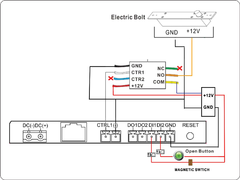
Electronic Bolt
Electronic Bolt
The Electronic Bolt is closed
when +12 V is supplied.
The Electronic Bolt is opened
when +12V is not supplied.
This function can let you not only press the
pound key to open the door when the Video
Door Phone is ringing but open the door with the Open Button directly.
MANUAL FOR SYSTEM INTEGRATOR
76
DI2: Trigger Default Low (High ->Low) When the Open Button is pressed, the door will be opened.
DI1: Trigger Default High-> Low MS (Magnetic Switch) is open, which means door is not closed well.
NOTE: MS (Magnetic Switch) is used to detect whether the door is closed or not, and the 1K Resistance is used to
protect your device.
When the wire connection is completed, we
need to select the “Positive” for Electronic Bolt
on the GPIO page of Entrance Setting on
DP3010R WEB User Interface.
DP3010R VIDEO DOOR PHONE
77
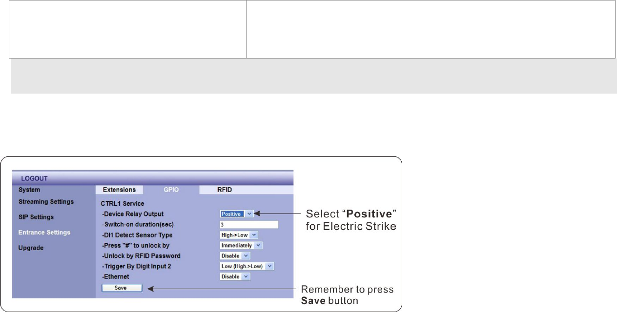
Electronic Strike
Electronic Strike with Open Button
The Electronic Strike is opened
when +12 V is supplied.
The Electronic Strike is closed
when +12V is not supplied.
This function lets you not only press the pound
key to open the door when the Video Door Phone
is ringing but open the door with the Open
Button directly.
When the wire connection is completed, we need
to select the “Negative” for Electronic Strike on
the GPIO page of Entrance Setting on DP3010R
WEB User Interface.
MANUAL FOR SYSTEM INTEGRATOR
78
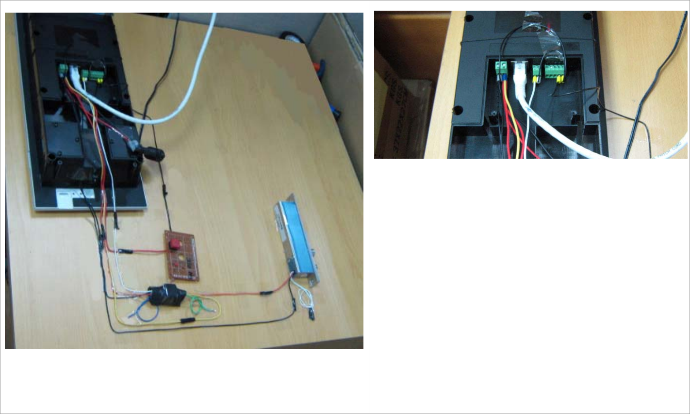
Example of the wiring for Electronic Lock with Open Door Button
Here we show an example of the wiring for Electronic Lock
with Open Door Button. In addition to Electronic Lock and
Open Door Button, we use wires, Relay Board, Core End
Terminal, 2-pin and 5-pin Terminal Block to build circuit.
It’s necessary to connect with Ethernet cable and external
DC power. Also, you need to configure WEB UI as previous
section mentions.
If all above steps are correct, you can press Door Open
Button to trigger the Electronic Lock (open door).
For more detailed information, please refer to next page.
DP3010R VIDEO DOOR PHONE
79
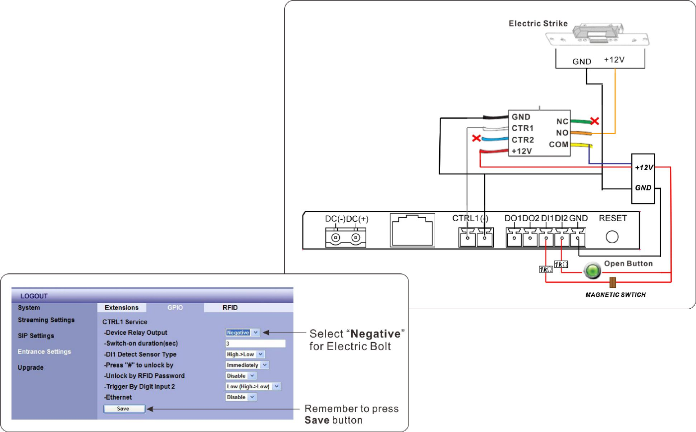
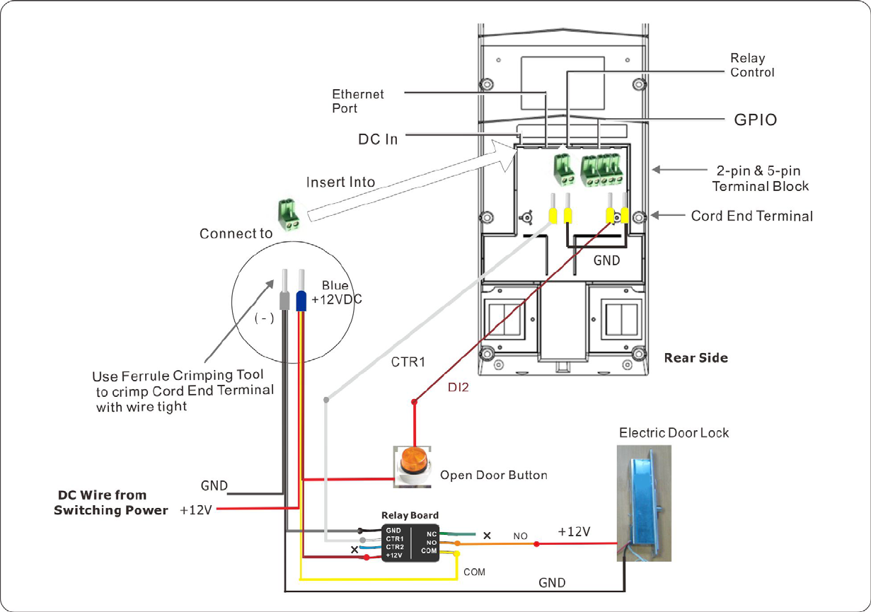
Diagram of the wiring for Electronic Lock with Open Door Button
MANUAL FOR SYSTEM INTEGRATOR
80
Both Electronic Bolt and Electronic Strike would have the same wire connection to connect to DP3010R and Open Door Button.
However, the difference for Electronic Bolt and Electronic Strike is in WEB UI configuration. Please refer to following settings.
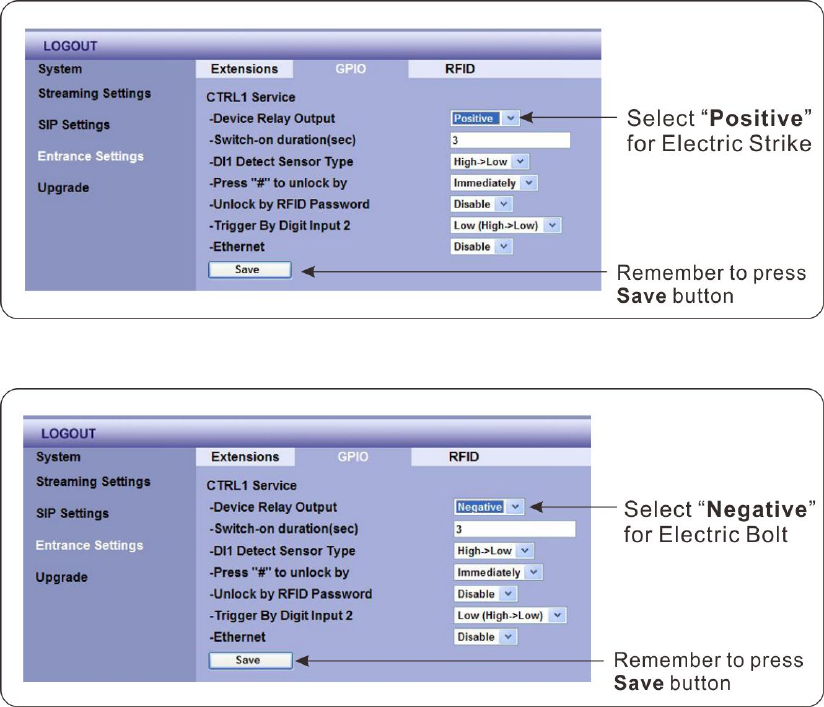
Configure WEB UI for Electronic Bolt
Configure WEB UI for Electronic Strike
When the wire connection is completed, we
need to select the “Positive” for Electronic Bolt
on the GPIO page of Entrance Setting on
DP3010R WEB User Interface.
When the wire connection is completed, we need
to select the “Negative” for Electronic Strike on
the GPIO page of Entrance Setting on DP3010R
WEB User Interface.
82
CE DECLARATION OF CONFORMITY (EUROPE)
Manufacturer declares that this product conforms to the specifications listed below, following the provisions of the European
R&TTE directive 1999/5/EC:
EN 301 489-1, 301 489-17 General EMC requirements for Radio equipment
EN 609 50 Safety
EN 300-328-1, EN 300-328-2 Technical requirements for Radio equipment
Caution: This equipment is intended to be used in all EU and EFTA countries. Outdoor use may be restricted to certain
frequencies and/or may require a license for operation. Contact local Authority for procedure to follow.
Note: Combinations of power levels and antennas resulting in a radiated power level of above 100 mW equivalent isotropic
radiated power (EIRP) are considered as not compliant with the above mentioned directive and are not allowed for use within
the European community and countries that have adopted the European R&TTE directive 1999/5/EC.