Ambient Systems GW3000 2.4GHz RFID Gateway User Manual
Ambient Systems B.V. 2.4GHz RFID Gateway
User Manual
User Manual
3000 SERIES 3rd GENERATION ACTIVE RFID
User Manual
3r d G e n e r a t i o n A c t i v e R F I D
Ambient Systems B.V.
Colosseum 15D ● 7521 PV Enschede ● the Netherlands
tel:(+ 31) (0)88 AMBIENT (+31 88 2624368 ) ● fax: (+31) (0)88 2624399
KvK: 08122911 ● VAT NL: 812976253B1 ● www.ambient-systems.net
1/73 Ambient Systems B.V.

User Manual
3000 SERIES 3rd GENERATION ACTIVE RFID
1 Table of Contents
1 Preface.......................................................................4
1.1 What is 3rd Generation Active RFID?..........4
1.2 What is Ambient Studio?...............................4
1.3 3000 Series Features........................................4
1.4 Conventions.....................................................5
1.5 Definitions........................................................5
1.6 Further Information........................................6
2 Introduction.............................................................7
2.1 About This Manual.........................................7
2.2 Related Documentation..................................7
3 Product Overview...................................................8
3.1 System Requirements.....................................9
3.2 Compliance(s)..................................................9
3.3 Hardware Overview and Specifications....11
4 Ambient Network.................................................16
4.1 Nodes..............................................................16
4.2 Network Layout............................................16
5 Installation.............................................................18
5.1 Before you Begin...........................................18
5.2 Wireless Considerations...............................18
5.3 Getting Started: Ambient Studio.................19
5.4 Getting Started: Nodes.................................20
6 Configuration........................................................26
6.1 Connecting to the Serial Device..................26
6.2 Set date and time...........................................29
6.3 Deployment....................................................29
6.4 Enabling built-in backup batteries..............31
6.5 localization.....................................................31
6.6 DNCP..............................................................37
6.7 Security...........................................................37
6.8 Temperature monitoring..............................37
6.9 Logging and flushing...................................41
6.10 Coexisting Networks..................................43
7 Deployment...........................................................45
7.1 Preparations...................................................45
7.2 Deployment Planning...................................46
7.3 Deployment Execution.................................50
7.4 A Few More Pointers....................................52
8 Example Deployments.........................................54
8.1 Example: Office Building.............................54
8.2 Example: Warehouse....................................54
9 Firmware Upgrades..............................................58
9.1 Gateway..........................................................58
9.2 MicroRouter...................................................59
9.3 SmartPoint......................................................60
9.4 Remarks..........................................................61
10 Troubleshooting..................................................62
10.1 Troubleshooting the serial connection.....62
11 Appendices...........................................................63
11.1 Appendix A: WSN Basics..........................63
11.2 Appendix B: Networking Basics...............66
11.3 Appendix C: Technical Specifications......69
11.4 Appendix D: Technical Support...............70
11.5 Appendix E: Warranty & Disclaimer.......71
11.6 Appendix F: Recycling...............................72
11.7 Appendix G: Registration..........................72
11.8 Appendix H: Manual Revisions................73
2/73 Ambient Systems B.V.

User Manual
3000 SERIES 3rd GENERATION ACTIVE RFID
3/73 Ambient Systems B.V.

User Manual
3000 SERIES 3rd GENERATION ACTIVE RFID
1 Preface
1.1 What is 3rd Generation Active RFID?
First there was conventional active RFID where a battery in the tag permits it to initiate a signal, give
longer range, manage a sensor or otherwise improve on the capability of a passive RFID tag. Second
generation active RFID is the Real Time Locating System (RTLS) where people or things are located
almost continuously from 30-300 meters away, usually by using many emitters. The third generation
of active RFID build on the power of mesh networking – also known as Wireless Sensor Networks
(WSN) – that provide better scalability, self-healing functionalities, increased capabilities and are
affordable. The third generation of active RFID tags combine all functionalities of previous active
RFID systems, identification and localization, and add to it with sensor extensions, file systems, and
so forth.
Ambient Systems, with its 3000 Series product line, provides 3rd Generation Active RFID products
that combine check, track, and trace functionalities:
•Check – Monitor the status of objects using e.g. temperature sensors
•Track – Locate your objects using RTLS functionality
•Trace – Maintain history of your objects using e.g. temperature logs and consignment notes.
The 3000 Series 3rd Generation Active RFID products are based on Ambient Wireless Sensor Network
(WSN) technology and communicate using IEEE PHY 802.15.4 at a frequency of 2.4 GHz.
1.2 What is Ambient Studio?
Ambient Studio 3000 is PC software that is used in conjunction with the 3000 Series 3rd Generation
Active RFID. Ambient Studio is used for deployment and configuration of a 3000 Series network,
data collection and data dissemination. It builds on the Ambient Device Driver Interface (DDI). DDI
allows addressing all nodes in your network as well as their resources in a uniform manner. Ambient
Studio also provides tools for e.g. remotely upgrading your infrastructure, managing the Remote
File System, and so forth.
The 3000-Series network products can operate standalone or use Ambient Studio as an intermediate.
1.3 3000 Series Features
●Easy to install 3rd Generate Active RFID
●Conforms to IEEE 802.15.4 PHY
●Benefits from the power of Wireless Mesh Networking
○Multi-hop
○Self-configuring
○Self-healing
●SmartPoints can be used to check, track and trace assets
○Built-in Temperature Sensor
○Built-in RTLS 3D Location Engine
4/73 Ambient Systems B.V.

User Manual
3000 SERIES 3rd GENERATION ACTIVE RFID
○Typical battery life of >3 years1
○User-configurable temperature & positioning intervals
○User-configurable security features
○User-configurable sleep modes
○User-configurable alerts
○Dynamic Event Reporting
■Temperature Alerts
■Low Battery Alerts
○Single screw Mounting
○SensIO Connector
■SPI
■I2C
■1-Wire®2
1.4 Conventions
This user manual uses the following typographical conventions to mark certain portions of text: new
terms, foreign phrases, and other important passages are emphasized in italics.
Everything that represents input or output of the computer, in particular commands, program code,
and screen output, is shown in a mono-spaced font (example) and separated by borders. Within
such passages, italics (example) indicate place-holders; you must insert an actual value instead of
the place-holder. On occasion, parts of program code are emphasized in bold face (example), if they
have been added or changed since the preceding example.
Important comments or reminders are indicated in bold and separated by borders, as follows:
Example
An administrator is generally a person who is in charge of installing and running Ambient Studio. A
user could be anyone who is using, or wants to use, any part of the Ambient Studio system. These
terms should not be interpreted too narrowly; this user manual does not have fixed presumptions
about system administration procedures.
1.5 Definitions
S h o r t - h a n d D e s c r i p t i o n
AGW Auxiliary Gateway
AS Ambient Studio
DDI Device Driver Interface
DDIP DDI Processor (a processor capable of interpreting DDI)
1 Depending on configuration, battery condition, network setup and environmental conditions. Default configuration for this setup
is sampling, logging and transmitting the temperature sensor every 5 minutes, localization once per hour.
2 1-Wire® is a registered trademark of Dallas Semiconductor Corporation
5/73 Ambient Systems B.V.
User Manual
3000 SERIES 3rd GENERATION ACTIVE RFID
DNCP Dynamic Node Configuration Protocol
GUI Graphical User Interface
GW Gateway
MGW Master Gateway
MR MicroRouter
OTA Over-the-air
PA Power Amplifier
RF Radio Frequency
RR Rapid Reader
RTLS Real-Time Location System
SP SmartPoint
SPI Serial Peripheral Interface
SPP Serial Port Protocol
WSN Wireless Sensor Network
1.6 Further Information
Besides the documentation, that is, this user manual, there are other resources about Ambient
Studio:
•FAQ – The FAQ list contains continuously updated answers to frequently asked questions.
•Web Site – The Ambient Systems support web site carries details on the latest release and other
information to make your work or play with Ambient Studio more productive.
6/73 Ambient Systems B.V.
User Manual
3000 SERIES 3rd GENERATION ACTIVE RFID
2 Introduction
This Ambient Systems 3000-Series User Manual describes how to use Ambient Systems products.
This manual covers the complete 3000-Series product range and includes Gateways, MicroRouters
and SmartPoints.
The 3000-Series network products can operate stand-alone. Ambient Studio can be used for
deployment, configuration and maintenance of the network. Please read the Ambient Studio user
manual on how to install and use Ambient Studio, see “Ambient Studio User Manual”.
The 3000 Series products are based on Ambient Wireless Sensor Network (WSN) technology and
communicate using IEEE 802.15.4 at a frequency of 2.4 GHz.
2.1 About This Manual
This manual provides practical information for installing 3rd Generation Active RFID systems using
Ambient products. The manual provides an overview of the 3000 Series product range, a short
theoretical background on WSN technology and detailed information on how to install each product
of the 3000 Series.
2.2 Related Documentation
D o c u m e n t D e s c r i p t i o n
Data Sheet:
GW3000
Contains detailed information about the 3000-Series
Gateway.
Data Sheet:
MR3000
Contains detailed information about the 3000-Series
MicroRouter.
Data Sheet:
SP3000
Any of the data sheets of 3000-Series SmartPoints, such as
the SP3000
White Paper:
Ambient 3000 Series Network
This white paper explains in detail how the Ambient 3000-
Series network works. It provides information that is
useful when installing a network.
White Paper:
Ambient 3000 Series Localization
This white paper explains in detail how the Ambient 3000-
Series localization mechanism works. It provides detailed
information that is useful when installing a localization-
enabled network.
User Manual:
3000 Series 3rd Generation Active RFID
Contains detailed information about installing, deploying
and configuring 3000 Series network products.
Specification:
Serial Port Protocol
This specification describes the underlying serial line
protocol that Gateways use to communicate over RS232
Specification:
Device Driver Interface
This specification describes the Device Driver Interface
protocol and message encapsulation scheme that is used to
access resources on Ambient products and peripheral
devices attached to Ambient products.
Data sheets and white papers can be downloaded from our website (see www.ambient-
systems.net/partners), user manuals and specifications are provided with 3000 Series products upon
request (contact support@ambient-systems.net).
7/73 Ambient Systems B.V.

User Manual
3000 SERIES 3rd GENERATION ACTIVE RFID
3 Product Overview
The 3000-Series products provide a 3rd Generation Active RFID system based on Ambient wireless
multi-hop mesh network technology.
An Ambient network consists of GateWays (GW), MicroRouters (MR), and SmartPoints (SP). GWs
and MRs are normally powered by mains. They have a rechargeable back-up power supply that
takes over in case of a temporary power blackout. Battery warnings of such an event are given
immediately. SPs are fully battery-operated and – using typical settings – last for more than 5 years
(SP3000). Battery warnings are given well in advance of the eventual depletion of the battery. Upon
battery depletion SmartPoints can be returned to Ambient Systems for refurbishing or replaced with
new SmartPoints.
A GW connects to a peripheral device using a RS232 serial cable. Ambient Studio is a software
application that is used to monitor and configure the network using various Graphical User Interface
(GUI) components.
WARNING: Any modifications to the units, unless expressly approved by the party responsible for
compliance, could void the user's authority to operate the equipment.
E l e m e n t D e s c r i p t i o n
GateWay:
GW3000
The heart of the Ambient Network is the GW. It controls the network
configuration and provides an interface to the network for the outside world by
means of a RS232 serial communication port.
There needs to be at least 1 GW per network which is the Master Gateway; a
network cannot operate without one. Auxiliary Gateways1 can be used to
increase redundancy and network bandwidth.
MicroRouter:
MR3000
MRs build up the rest of the network infrastructure. A MR can join a network
when in range. As a part of the network it is able to receive and send data to
other nodes. If the MR has no direct connection to the GW its messages are
relayed by intermediate MRs.
Depending on the type of GW, up to 255 MRs can join a single network.
SmartPoint:
SP3000
SPs are battery-operated Active RFID tags. SPs have one or more sensors
attached which allows it to monitor environmental parameters. The SP3000, for
example, has an on-board EN12830 compliant temperature sensor.
Using various configuration mechanisms, the behaviour of the SP can be
modified Over-the-Air (OTA). The beacon messages of the GWs and MRs
provide information which the SP uses to obtain a position estimate; as a result
a SP knows its own location.
1 Auxiliary Gateways are not yet commercially available
8/73 Ambient Systems B.V.

User Manual
3000 SERIES 3rd GENERATION ACTIVE RFID
Ambient Studio:
AS3000
Ambient Studio is PC software that is used to deploy, monitor, maintain and
configure the network. Using various GUI components every device in the
network and every resource of that device is wireless accessible.
Ambient Studio is also used to set up all the localization peripherals; once set
up, the network operates standalone.
RapidReader:
Not yet
commercially
available
A RapidReader2 is a standalone device that is capable of creating a point-to-
point connection with an Ambient device, providing an improved bandwidth,
making it easier to configure and update devices.
3.1 System Requirements
3.1.1 3000 Series
P o w e r Mains power connections at locations where infrastructure
(Gateway and MicroRouters) need to be placed
C o n n e c t i v i t y RS232 SUB-D9 connection with 115200 baud and hardware flow
control enabled for communicating with the Gateway
3.1.2 Ambient Studio
O p e r a t i n g S y s t e m Windows XP® SP3 or Vista®
P r o c e s s o r 300 MHz or higher
M e m o r y 128 MB RAM or higher
S t o r a g e 500 MB available hard disk space (for logging purposes)
D i s p l a y 1024 x 600 or higher resolution video adapter and monitor
P e r i p h e r a l s •Keyboard
•Mouse or compatible pointing device
•1 or more RS232 serial ports OR
•1 or more USB port2
3.2 Compliance(s)
The SmartPoint SP3000, MicroRouter MR3000 and Gateway GW3000 are compliant with FCC part
15.247 and part 15B, IC RSS-210 and RSS GEN and have safety certification according to CB and
cCSAus. All three devices above are marked on the product or packaging label with the following
statements:
2 The RapidReader is not yet commercially available
2 If no COM port is available on your system, you can purchase a USB to serial converter at any electronics shop
9/73 Ambient Systems B.V.

User Manual
3000 SERIES 3rd GENERATION ACTIVE RFID
“This device complies with Part 15 of the FCC Rules. Operation is subject to the following two
conditions: (1) this device may not cause harmful interference, and (2) this device must accept any
interference received, including interference that may cause undesired operation.” This is described
in Part 15.19 (a)(3) and (5).”
“This Class B digital apparatus complies with Canadian ICES-003. Cet appareil numerique del la
classe B est conforme al norme NMB-003 du Canada.”
Note (applicable for all above devices): This equipment has been tested and found to comply with
the limits for a Class B digital device pursuant to Part 15 of the FCC Rules. These limits are designed
to provide reasonable protection against harmful interference in a residential installation. This
equipment generates, uses, and can radiate radio frequency energy and, if not installed and used in
accordance wit the instructions, may cause harmful interference to radio communications.
However, there is no guarantee that interference will not occur in a particular installation. If this
equipment does cause harmful interference to radio or television reception, which can be determined
by turning the equipment off and on, the user is encouraged to try and correct the interference by
one or more of the following measures:
-Reorient or relocate the receiving antenna.
-Increase the separation between the equipment and the receiver.
-Connect the equipment into an outlet on a circuit different from that to which the receiver is
connected.
-Consult the dealer or an experienced radio/TV technician for help.
Additionally compliances:
●EN12830 (Excluding GW3000)
●RoHS
A copy of the certificates can be obtained by sending an email to support@ambient-systems.net.
EN12830 (Class 1 accuracy, class D climatic environment, suitable for transportation)
10/73 Ambient Systems B.V.
User Manual
3000 SERIES 3rd GENERATION ACTIVE RFID
3.3 Hardware Overview and Specifications
This section provides an overview of the various hardware components that make up an Ambient
3000 Series network including a summary of the technical specifications of each device.
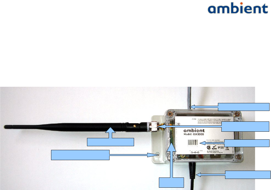
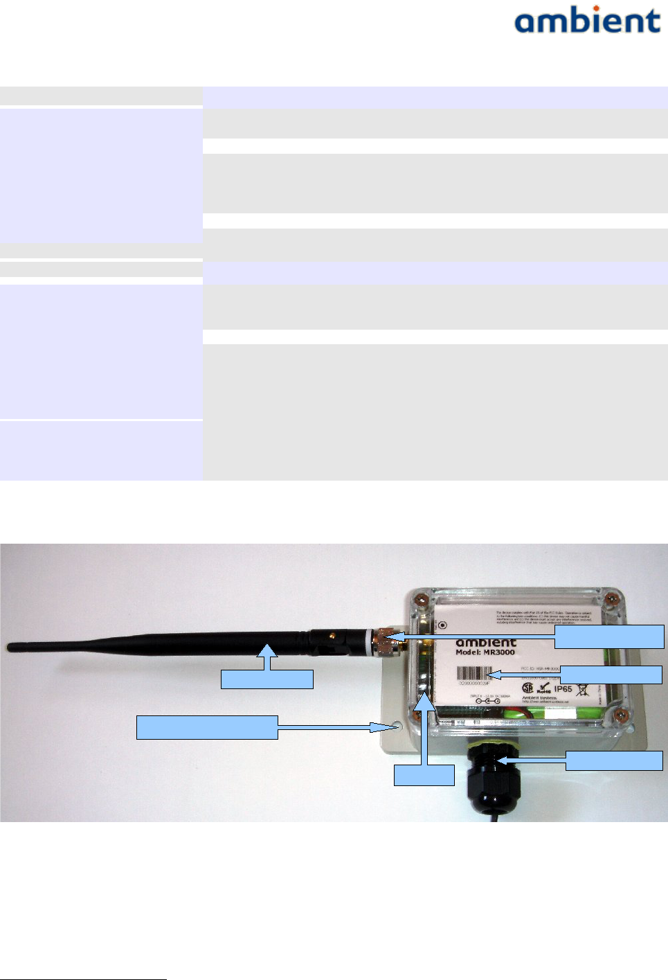
3.3.1 Gateway GW3000
Supplied Accessories:
●Swivel Antenna
○SubMinature version A Reverse Polarity Connector (RP-SMA)
●RS232 Serial Cable
○Registered Jack 11 (RJ11) to SUB9
●AC / DC Adapter (100-240VAC, 12VDC, max 500 mA), 60950-1 certified
11/73 Ambient Systems B.V.
SMA Connector
Screw Holes
ID & Barcode
DC Plug
LEDs
SMA Antenna
RJ11 Serial Plug
User Manual
3000 SERIES 3rd GENERATION ACTIVE RFID
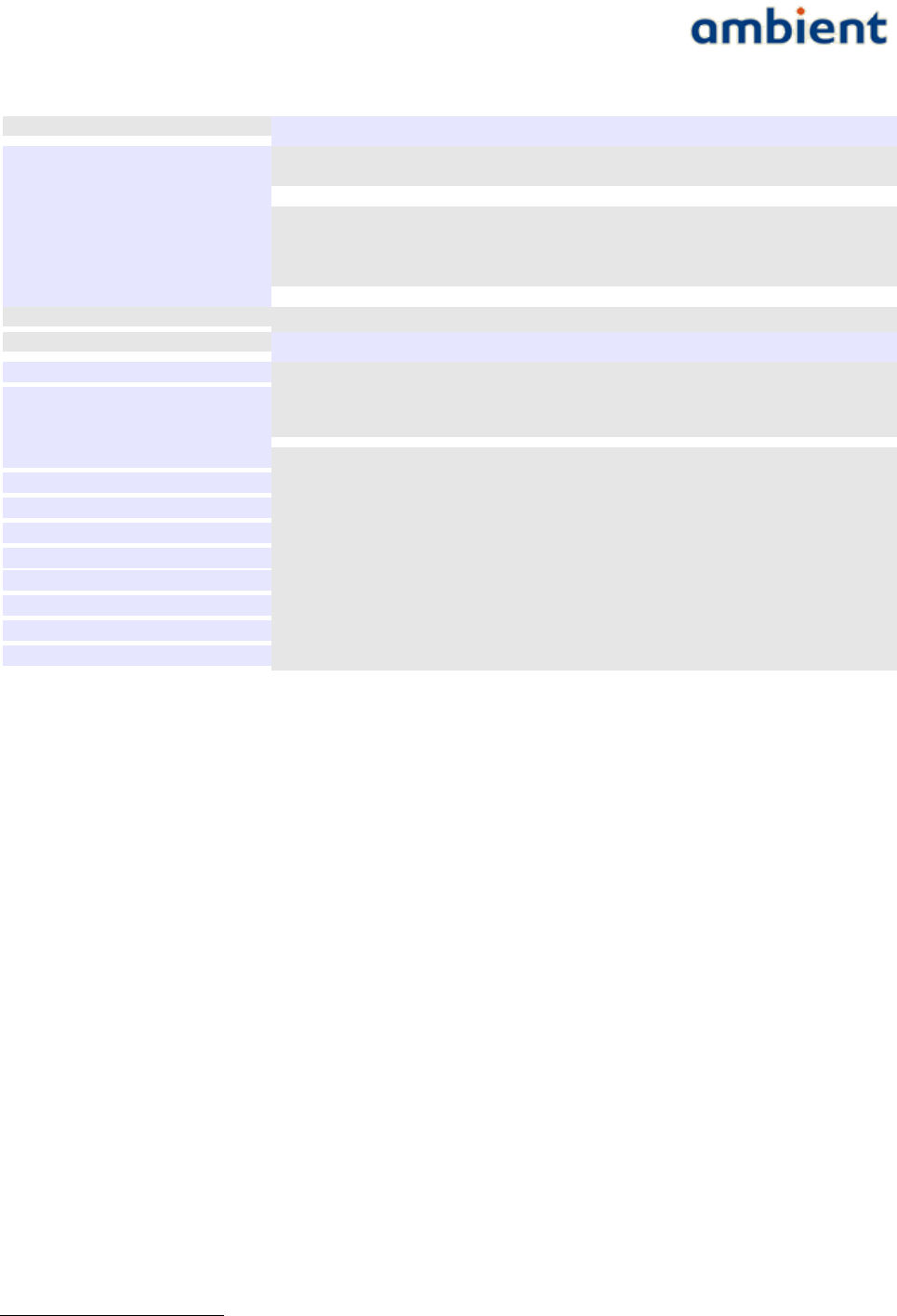
T e c h n i c a l S p e c i f i c a t i o n s
F r e q u e n c y R a n g e * 2.42 to 2.455 GHz, IEEE 802.15.4 PHY compliant
T X ( M a x i m u m r a d i a t e d
p o w e r ( E I R P ) )
TBD
R X s e n s i t i v i t y -103.6 dBm @ 1%PER
T y p i c a l R a n g e i n d o o r TBD
T y p i c a l R a n g e o u t d o o r TBD
T y p i c a l B a c k u p B a t t e r y
L i f e
5 days1
I n t e r f a c e RS232
P h y s i c a l S p e c i f i c a t i o n s
M o u n t i n g Enclosure with 4 screw mounting holes
D i m e n s i o n s ( H x W x D )
D i m e n s i o n s w i t h o u t
flanges (H x W x D)
50 x 68 x 131 mm (excluding antenna)
50 x 68 x 100 mm (excluding antenna)
W e i g h t 232 gr (excluding adapter)
C o l o u r Gray
P o w e r S o u r c e External, 6.0 – 12.6 V, 500 mA
B a c k u p B a t t e r y 3 x rechargeable AA Nickel Metal Hybrid
A n t e n n a External omni-directional swivel antenna (RP-SMA connector), see 3.3.3
O p e r a t i n g T e m p e r a t u r e -20˚C to +50˚C
S t o r a g e T e m p e r a t u r e -20˚C to +50˚C
I n g r e s s P r o t e c t i o n IP20
R o H S yes
*the radio frequency range is restricted to the above in accordance with FCC certification
3.3.2 MicroRouter MR3000
Supplied Accessories:
●Swivel Antenna
○SubMinature version A Reverse Polarity Connector (RP-SMA)
●AC / DC Adapter (100-240VAC, 12VDC, max 500 mA), 60950-1 certified
○For outdoors use, the AC/DC adapter needs to be outdoors rated
1 Typical reporting intervals, always in network, backup battery fully charged
12/73 Ambient Systems B.V.
SMA Connector
Screw Holes
ID & Barcode
DC Gland
LEDs
Antenna
User Manual
3000 SERIES 3rd GENERATION ACTIVE RFID
T e c h n i c a l S p e c i f i c a t i o n s
F r e q u e n c y R a n g e * 2.42 to 2.455 GHz, IEEE 802.15.4 PHY compliant
T X ( M a x i m u m r a d i a t e d
p o w e r ( E I R P ) )
TBD
R X s e n s i t i v i t y -103.6 dBm @ 1%PER
T y p i c a l R a n g e i n d o o r TBD
T y p i c a l R a n g e o u t d o o r TBD
T y p i c a l B a c k u p B a t t e r y
L i f e
5 days1
P h y s i c a l S p e c i f i c a t i o n s
M o u n t i n g Enclosure with 4 screw mounting holes
D i m e n s i o n s ( H x W x D )
D i m e n s i o n s w i t h o u t
f l a n g e s / g l a n d ( H x W x D )
50 x 97 x 131 mm (excluding antenna)
50 x 68 x 100 mm (excluding antenna)
W e i g h t 232 gr (excluding adapter)
C o l o u r Gray
P o w e r S o u r c e External, 6.0 – 12.6 V, 500 mA
B a c k u p B a t t e r y 3 x rechargeable AA Nickel Metal Hybrid
A n t e n n a External omni-directional swivel antenna (RP-SMA connector), see 3.3.3
O p e r a t i n g T e m p e r a t u r e -40˚C to +85˚C
S t o r a g e T e m p e r a t u r e -40˚C to +85˚C
I n g r e s s P r o t e c t i o n IP65
R o H S yes
*the radio frequency range is restricted to the above in accordance with FCC certification
3.3.3 Important note, GW3000 and MR3000 antennas
The GW3000 and MR3000 devices have been designed to operate with the antennas listed below,
and having a maximum gain of 5 dBi. Antennas not included in this list or having a gain greater than
5 dBi are strictly prohibited for use with this device. The required antenna impedance is 50 ohms.
●2.2dBi gain, swivel antenna – TLB-2400-900LD-2.2A
●5dBi gain, swivel antenna – TLB-2400-900LD-5A
To reduce potential radio interference to other users, the antenna type and its gain should be so
chosen that the equivalent isotropically radiated power (e.i.r.p.) is not more than that permitted for
successful communication.
WARNING: Any modifications to the units, unless expressly approved by the party responsible for
compliance, could void the user's authority to operate the equipment.
In order to comply with the RF Exposure requirements of Industry Canada and the FCC, a minimum
of 20cm separation distance must be maintained between the antenna of this device and all persons.
1 Typical reporting intervals, always in network, backup batteries fully charged
13/73 Ambient Systems B.V.
User Manual
3000 SERIES 3rd GENERATION ACTIVE RFID
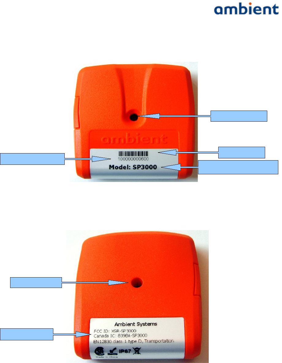
3.3.4 SmartPoint SP3000
FRONT
BACK
14/73 Ambient Systems B.V.
ID Barcode
Product Model Name
ID (hexadecimal)
Screw hole
Backside Label
Screw hole
User Manual
3000 SERIES 3rd GENERATION ACTIVE RFID
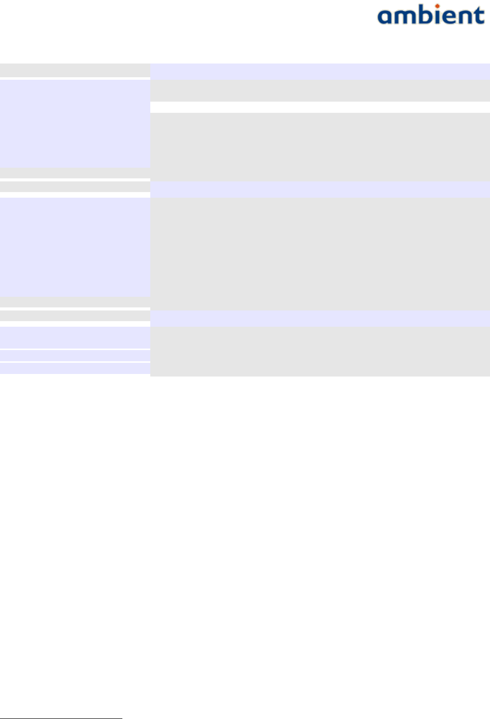
T e c h n i c a l S p e c i f i c a t i o n s
F r e q u e n c y R a n g e * 2.405 to 2.475 GHz, IEEE 802.15.4 PHY compliant
T X ( M a x i m u m r a d i a t e d
p o w e r ( E I R P ) )
+4.6dBm (including PCB antenna gain)
R X -85.0 dBm @ 1%PER
T y p i c a l R a n g e i n d o o r 25 m
T y p i c a l R a n g e o u t d o o r 50 m
T y p i c a l B a t t e r y L i f e 5 years1
T y p i c a l R e p o r t i n g R a t e 5 minutes (2 seconds – 18 hours)
P h y s i c a l S p e c i f i c a t i o n s
M o u n t i n g Single screw mounting hole
D i m e n s i o n s ( H x W x D ) 59.6 x 56.6 x 14.0 mm
W e i g h t 44 gr
C o l o u r Orange
B a t t e r y 2 x AAA Lithium Thionyl Chloride
A n t e n n a Integrated on PCB, Omni-directional
O p e r a t i n g T e m p e r a t u r e -40˚C to +85˚C
S t o r a g e T e m p e r a t u r e -40˚C to +85˚C
I n g r e s s P r o t e c t i o n IP67 (Dust tight, water tight)
T e m p e r a t u r e
T y p i c a l a c c u r a c y ±0.5˚C from -25˚C to +85˚C
±1.0˚C from -40˚C to +85˚C
R e s o l u t i o n 0.0625˚C
R o H S yes
*the radio frequency range is restricted to the above in accordance with FCC certification
1 Sample & send temperature every 5 minutes, always in network with multiple routers in range.
15/73 Ambient Systems B.V.
User Manual
3000 SERIES 3rd GENERATION ACTIVE RFID
4 Ambient Network
This section explains what an Ambient Network is and where it consists of.
4.1 Nodes
An Ambient Network consists of a number of so-called 'nodes'. A combination of these nodes are
used to build an Ambient Network. As mentioned before, there are three (3) types of nodes which
are the Master Gateway, the MicroRouter, and the SmartPoint. A Gateway is considered to be a
Master Gateway unless indicated otherwise.
The GW is connected using a RS232 serial cable to a peripheral device (e.g. a PC or a GPRS logger).
GWs and MRs build up a network by creating dynamic links with each other. These links adapt to
the current deployment set up and environmental changes. SPs only communicate periodically with
one of the infrastructure nodes – i.e. GWs and MRs – when they have data to send (e.g. temperature
reading, location information, etc.).
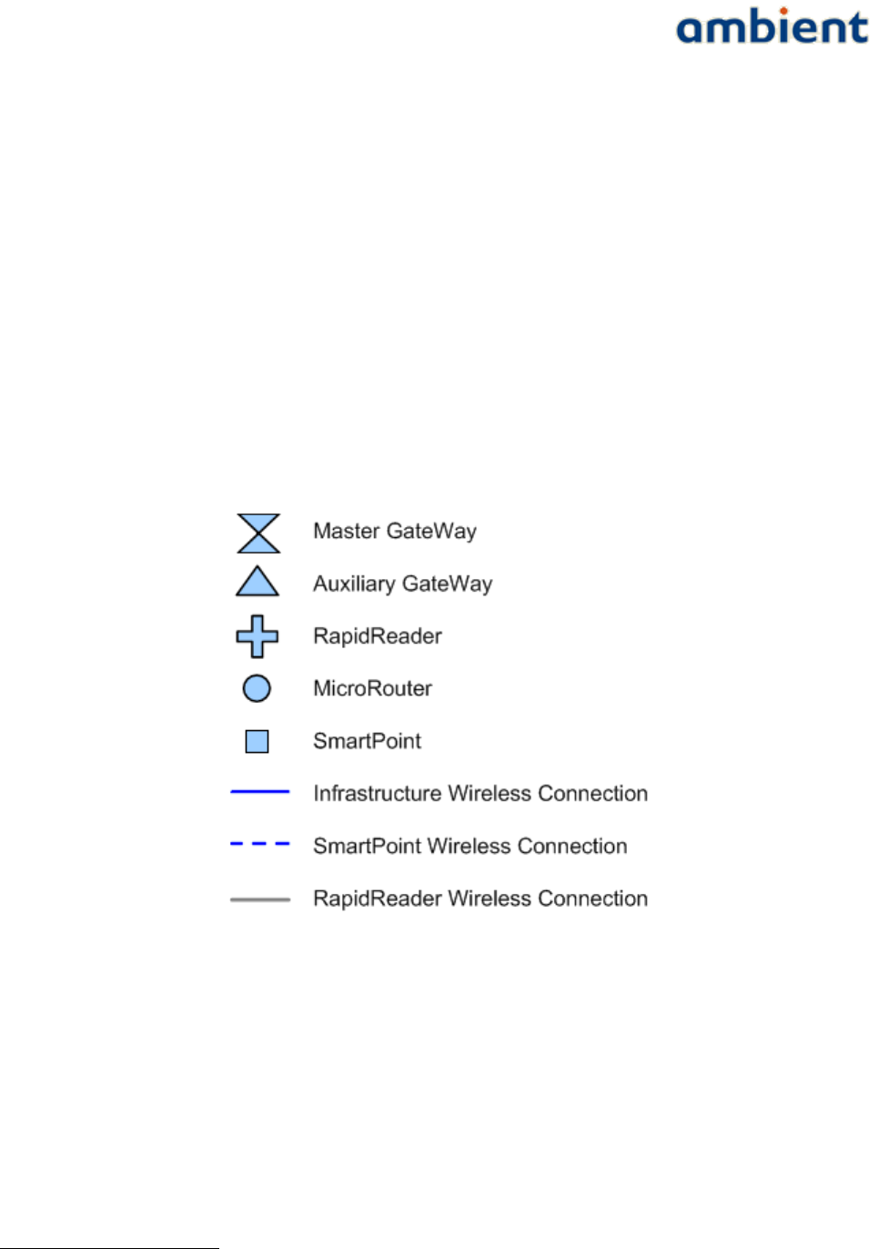
An overview of the symbols used for these nodes throughout this document is given in Illustration
11.
4.2 Network Layout
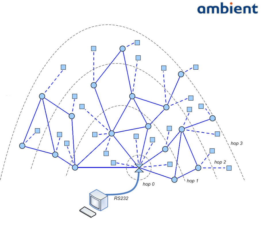
An example network layout is given in Illustration 2. The illustration shows a network with a GW,
MRs, and SPs. GWs and MRs maintain a permanent wireless connection with each other. In this way
they built up a backbone infrastructure.
The network is build up originating from the GW outward. SPs use short beacon messages that are
transmitted by both GWs and MRs to communicate with the infrastructure. These links are not
permanent but only exist only while the SP is communicating with the infrastructure.
1 The products Auxiliary Gateway and RapidReader will be released in 2009-2010. Auxiliary gateways can be used for load balancing
purposes in heavily loaded network. The RapidReader can be used to set-up a point to point connection to a device for faster
uploading/downloading files or configuration purposes.
16/73 Ambient Systems B.V.
Illustration 1: Overview of Ambient network
nodes
User Manual
3000 SERIES 3rd GENERATION ACTIVE RFID
As mentioned before, an Ambient network is a multi-hop network. Each GW and MR in the network
has a so-called hop count value. This value represents the number of times a message needs to be
forwarded by other MRs, to reach the GW.
Hop counts are measured from the GW. The GW has hop count 0. MRs in direct communication
range of the GW are on hop 1. MRs that are in range of a MR at hop 1 but are not in range with the
GW are on hop 2, and so forth. Maximum 15 hops are supported.
Eventually, the GW is connected to an PC or other device using an RS232 serial connection. The GW
thus provides the bridge between an Ambient network and your application.
17/73 Ambient Systems B.V.
Illustration 2: Example Ambient network layout with Hop Counts and Wired PC

User Manual
3000 SERIES 3rd GENERATION ACTIVE RFID
5 Installation
This section will guide you through the installation process. Placement of the GWs, MRs and SPs is
very important. The performance (range) of radio products is influenced by the objects which are
located between sender and receiver. This is explained in more detail in the next sections.
5.1 Before you Begin
Below is a list of items to consider before you begin the installation process. Ensure you have all the
equipment needed to perform an installation:
●PC or any other device running Windows XP or Windows Vista with a RS232 COM port
●Ambient Studio installation CD, or
●an Internet connection in order to download the installer from our website
●Gateway(s), MicroRouter(s), and SmartPoint(s)
(including AC/DC adaptors, SMA antennas, serial cables)
●Screws with a diameter of 5 mm and screwdriver to be used both for mounting the GW and
MRs
●Screws with a diameter of 4 mm and screwdriver to be used for mounting the SP
If your system does not have an RS232 COM port, you can purchase a USB to Serial converter which
is available at any regular electronics store.
5.2 Wireless Considerations
An Ambient network can be installed at basically any location. The network is built up solely on
wireless connections – with the exception of the GW and its serial connection – and mains.
Individual nodes can be added to the network from virtually anywhere within the operating range
of the individual nodes. Keep in mind, however, that the number, thickness and location of walls,
ceilings, or other objects that the wireless signals must pass through, may limit the range. Typical
ranges described in the data sheets vary depending on the types of materials and background Radio
Frequency (RF) noise in your home, business, warehouse, or any other place you are installing a
network. The key to maximizing wireless range is to follow these basic guidelines;
1. Keep the number of walls and ceilings between the different nodes (GW, MR, SP) to a
minimum – each wall or ceiling can reduce the range from a node. Position your devices so
that the number of walls or ceilings is minimized.
2. Be aware of the straight line between network nodes. A wall that is 0.5 meters (1.5 feet) thick
, at a 45-degree angle appears to be more than 1 meter (3 feet) thick. At a 2-degree angle it
looks over 14 meters (42 feet) thick! Position nodes so that the signal will travel straight
through a wall or ceiling (instead of an an angle) for better reception.
3. Building materials make a difference. A solid metal door or aluminium studs may have a
negative effect on range. Try to position nodes such that the signal passes through drywall
or open doorways. Material and objects such as glass, steel, metal, walls with insulation,
water (fish tanks), mirrors, file cabinets, brick, and concrete will degrade your wireless
signal considerably.
4. Keep your nodes away 1-2 meters (3-6 feet) from electrical devices or appliances that
18/73 Ambient Systems B.V.
User Manual
3000 SERIES 3rd GENERATION ACTIVE RFID
generate RF noise.
5. If you are using 2.4 GHz cordless phones, WLAN, or X-10 (wireless products such as ceiling
fans, lights, and home security systems), your wireless connection may degrade dramatically
or drop completely. Make sure your 2.4 GHz phone base is as far away from your wireless
nodes as possible. The base station transmits a signal even if the phone is not in use.
6. SPs have a shorter range than infrastructure nodes (GWs, MRs) due to the fact that they have
an integrated PCB antenna. When installing your infrastructure nodes, make sure you take
into account the fact that they are placed in such a fashion that they provide enough
coverage for SPs to communicate.
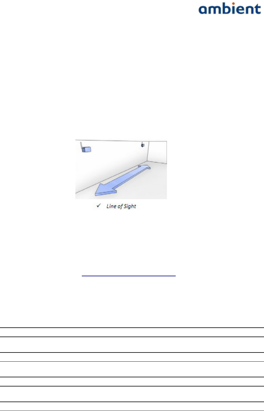
7. Mount the GW or MR in such way that the antenna is in vertical position. It points always to
the ceiling (or floor). This is depicted in Illustration 3.
More information regarding deployment can be found in the remaining chapters of this document.
5.3 Getting Started: Ambient Studio
Ambient Studio 3000 can be purchased from Ambient. The software can be downloaded from the
support section our website, at www.ambient-systems.net/partners. Make sure you download the
latest version of Ambient Studio. Use the 'Save As' option to store the installer file on your local hard
drive.
If you have older versions of Ambient Studio installed on your system, first uninstall those before
continuing with the new installation.
Once downloaded, go to:
Start -> Run
In the box that appears type:
C:\My Downloads\Ambient_Studio_3000_[X.YpZ].exe
where
C:\My Downloads
represents the location where you downloaded the installer to, and
[X.YpZ]
the version of the Ambient Studio installer.
19/73 Ambient Systems B.V.
Illustration 3: Correct antenna
orientation, vertical

User Manual
3000 SERIES 3rd GENERATION ACTIVE RFID
When the installer wizard appears, follow the on-screen instructions in order to install Ambient
Studio like you would with any other Windows software. During installation you can cancel the
process at any time by pressing 'Cancel'.
5.4 Getting Started: Nodes
5.4.1 Gateway GW3000
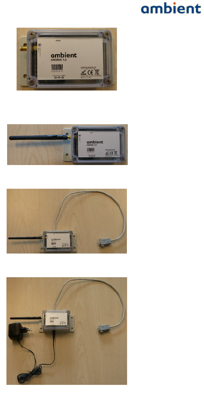
When installing a GW30001, first make sure that you have the right device, it should state GW3000
on the label, followed by a hardware version ID (see Illustration 4).
The GW3000 is installed in a few steps that are listed below;
1. Screw on the SMA antenna on the SMA connector (see Illustration 5)
NOTE: Do not turn on the GW30xx when the SMA antenna is not connected, it could
damage the device!
2. Push the RJ11 connector of the serial cable into the RJ11 socket (see Illustration 6).
NOTE: Make sure the RJ11 'clicks' in place to ensure that it is properly connected!
3. Connect the SUB9 connector of the serial cable to the COM port of your PC. Where possible,
use the screws of the serial connector to ensure it is tightly connected. The same applies
when you connect the GW to another peripheral device.
NOTE: Make sure the SUB9 connector is tightly connected, otherwise it may result in
packet errors over the serial line!
4. Push the jack of the AC/DC adapter in the AC/DC socket (see Illustration 7) and place the
adapter in a mains socket.
NOTE: If you do not push the jack fully in the socket, it might not be connected correctly!
NOTE: If you decide to use a different AC/DC adapter for the GW3000, it needs to be of
class 2-II with a cable length less than 3 meter, and with the correct specifications (DC
voltage & amperage, polarity and plug-size).
Mounting the GW is described in the deployment section of this user manual.
1 GW3000= GW3000, GW3120 or GW3250
20/73 Ambient Systems B.V.
User Manual
3000 SERIES 3rd GENERATION ACTIVE RFID
21/73 Ambient Systems B.V.
Illustration 4: GW3000 Installation preparation
Illustration 7: GW3000 Installation step 3
Illustration 5: GW3000 Installation step 1
Illustration 6: GW3000 Installation step 2

User Manual
3000 SERIES 3rd GENERATION ACTIVE RFID
5.4.2 MicroRouter MR3000
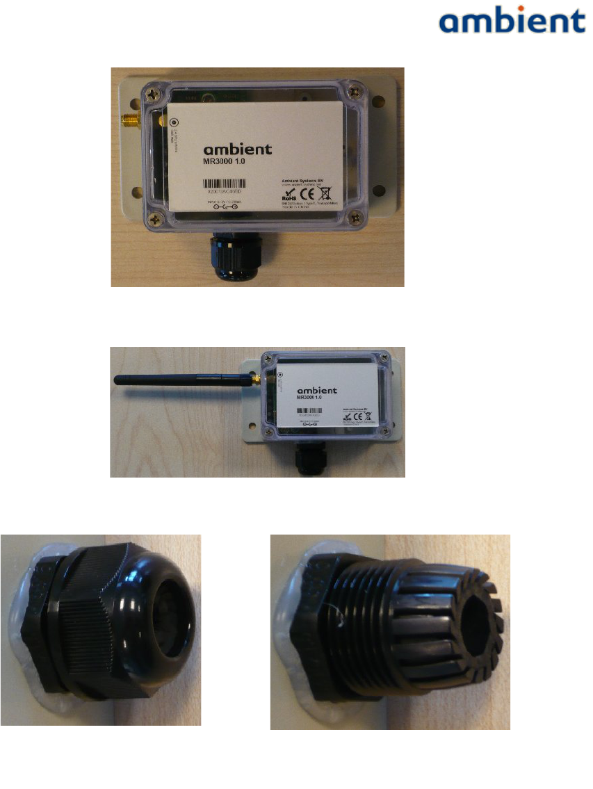
When installing an MR, first make sure that you have the right device, it should state MR3000 on the
label, followed by a hardware version ID (see Illustration 8).
The MR3000 is installed in a few steps that are listed below;
1. Screw on the SMA antenna on the SMA connector (see Illustration 9)
NOTE: Do not turn on the MR3000 when the SMA antenna is not connected, it could
damage the device!
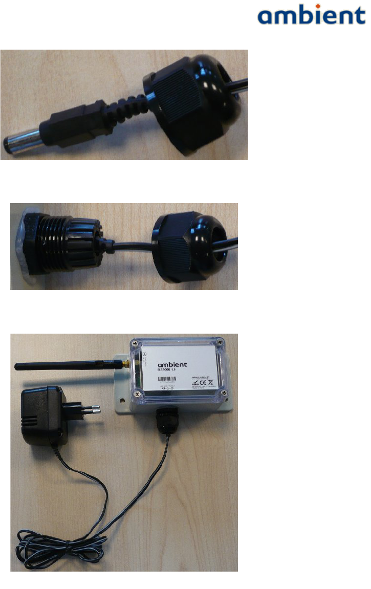
2. Remove the cap from the DC gland (see Illustration 10).
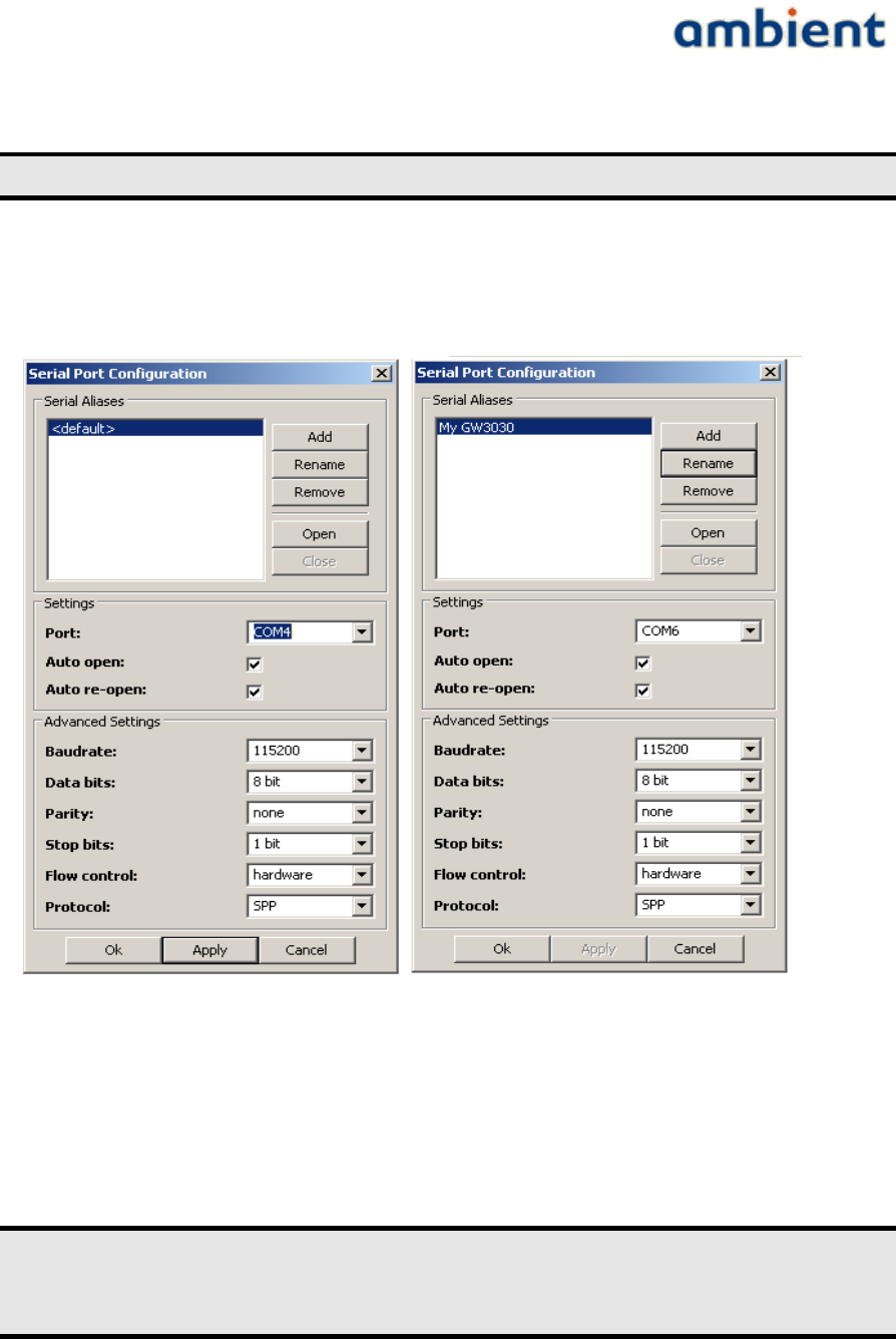
3. Push the DC jack of the adapter through the cap (see Illustration 11).
4. Push the DC jack through the DC gland until it fits tightly in its socket (see Illustration 12).
NOTE: The AC/DC gland opening may be a bit rigid when used for the first time, you can
carefully widen it to make jack go through easier.
NOTE: If you do not push the jack fully in the socket, it might not be connected correctly!
NOTE: Make sure the rubber ring on the inside of the gland stays in place, if it is not in
its right position it may result in the connector not being water tight!
NOTE: If you decide to use a different AC/DC adapter for the GW3000, it needs to be of
class 2-II with a cable length less than 3 meter, and with the correct specifications (DC
voltage & amperage, polarity and plug-size).
5. Screw the cap back on the gland (see Illustration 13).
NOTE: If you do not tightly screw on the cap of the gland, it may result in the connector
not being water tight!
6. Place the DC adapter in a mains socket.
Mounting the MR3000 is described in the deployment section of this user manual.
22/73 Ambient Systems B.V.
User Manual
3000 SERIES 3rd GENERATION ACTIVE RFID
23/73 Ambient Systems B.V.
Illustration 10: MR3000 Installation, step 2, left is gland with cap, right is
gland without cap
Illustration 8: MR3000 Installation, preparation
Illustration 9: MR3000 Installation, step 1
User Manual
3000 SERIES 3rd GENERATION ACTIVE RFID
24/73 Ambient Systems B.V.
Illustration 11: MR3000 Installation, step 3
Illustration 12: MR3000 Installation, step 4
Illustration 13: MR3000 Installation, step 5

User Manual
3000 SERIES 3rd GENERATION ACTIVE RFID
5.4.3 SmartPoint SP3000
The SP3000 does not require separate installation. It is 'always-on', meaning that when it wakes up
from its deep-sleep mode1 and it hears a network it will become a part of the network.
Please take into account that upon arrival, the SmartPoints are likely to be in a deep sleep mode to
save energy during transport. Once you have turned on your network, it can take up to two hours
for all SPs to awake2.
Mounting the SP is described in the deployment section of this user manual.
1 The deep-sleep mode is the default mode of the SmartPoint. In this mode it consumes as less energy as possible. Based on the
configuration of the various drivers, it wakes up to execute a task (like sampling the temperature driver). There are no other sleep
modes.
2 Assuming that no packets are missed.
25/73 Ambient Systems B.V.

User Manual
3000 SERIES 3rd GENERATION ACTIVE RFID
6 Configuration
This section discusses the configuration of the Ambient Systems 3000 series network through
Ambient Studio. Please, refer to Section 4.3 or Ambient Studio User Manual for installing Ambient
Studio. Throughout this section, we assume that Ambient Studio is successfully installed and is
running.
6.1 Connecting to the Serial Device
In order to have Ambient Studio communicate with your Series 3000 network, it is key to configure
the Serial Port. Typically, you only need to set the Serial Port options once. Below we describe how
to set the Serial Port configuration manually and how to check its settings.
6.1.1 Determine to which COM port your GW3000 is connected
First, we will determine to which COM port your GW3000 is connected. If you already know the
COM port, you can skip the remainder of Section 6.1.1 and go ahead to Section 6.1.2.
If your system does not have a serial port you can purchase e.g. a USB to RS232 converter from any
PC store. In case of a USB to RS232 converter, the USB driver (in Windows) will assign a COM
identifier to the serial port. You can ascertain this COM identifier by browsing to your device
manager. This is achieved using the following steps:
1. Select Windows Start Menu
2. Select 'Control Panel'. A new window will open up.
3. Select 'System'. A new dialogue will open up.
4. Select the 'Hardware' tab.
5. Select the button 'Device Manager'. A new dialogue will open up. The dialogue shows all
installed hardware components in a tree view.
6. Look for the entry 'Ports (COM & LPT) and expand it.
7. The expanded view will show you the list of COM ports installed, indicating some USB
remark as well, for example:
Prolific USB-to-Serial Comm Port (COM4)
8. You now know that your system has a COM4 installed and you can use this COM port in
Ambient Studio.
NOTE: In some cases Windows will immediately identify the USB-to-Serial
device without needing to install specific USB driver software, but some
USB-to-Serial converters can cause problems when incorrect drivers are
installed. Make sure you always use the recommended and latest drivers
available to prevent problems with your serial interface.
6.1.2 Setting Serial Port Configuration
Use the Serial Port Configuration dialogue in Ambient Studio to establish a connection between
26/73 Ambient Systems B.V.
User Manual
3000 SERIES 3rd GENERATION ACTIVE RFID
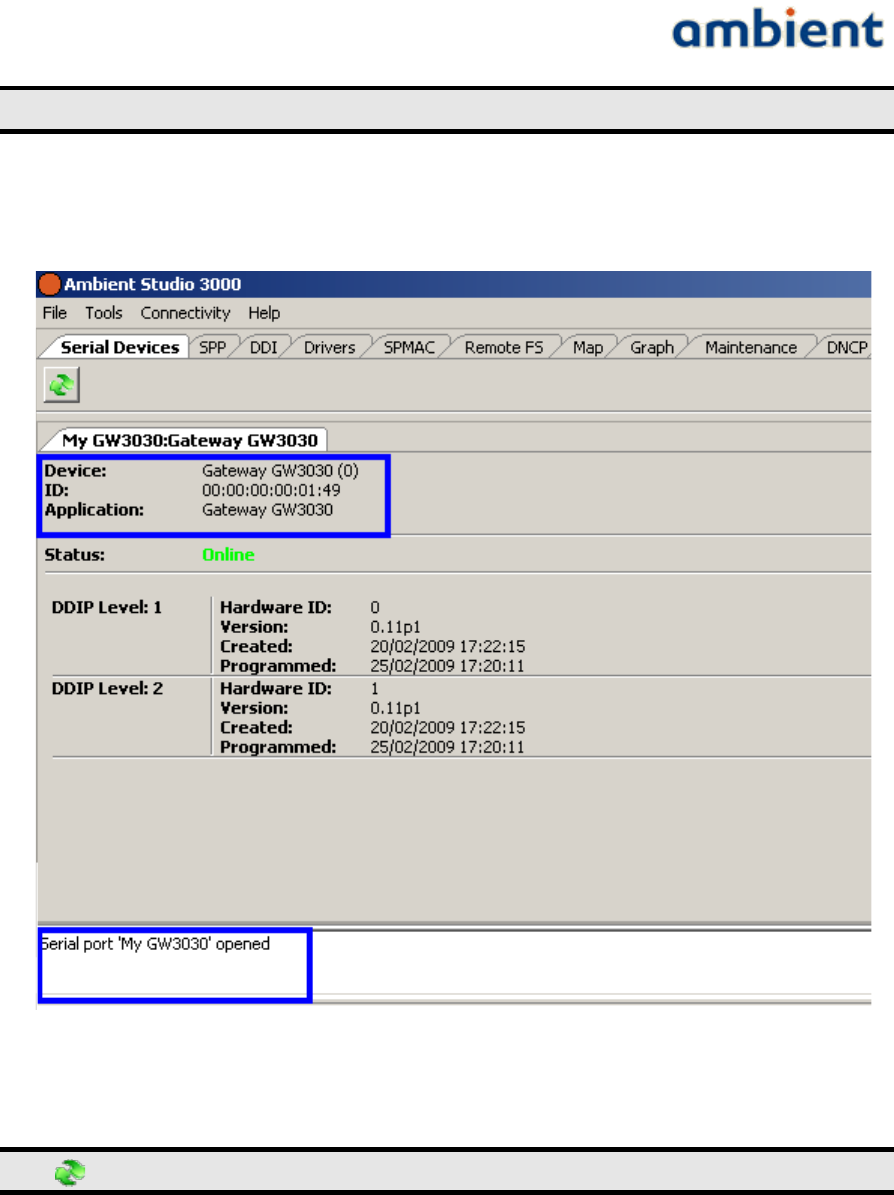
Ambient Studio and your network. The Serial Port Configuration dialogue is opened by clicking the
menu entry:
Connectivity Serial Port Configure.→ →
This dialogue can be used to add, remove and rename serial aliases, as well as open and close
individual aliases. For every serial alias specific settings can be set. Ambient Studio will
automatically fill in standard settings required to open a connection to a GW3000.
If you use Ambient Studio for the first time, it will automatically create a serial alias named
'<default>', that works on COM1, and attempt to open it. Using the buttons in the Serial Aliases
section, you can respectively add, rename, remove, open and close a serial alias.
In the 'Settings' section you can select the actual system Serial Port to connect to
and indicate whether the serial port should be automatically opened upon start
up (recommended). In the example, 'COM4' has been selected.
In the 'Advanced Settings' section, you can modify parameters of the serial port. Normally, you do
not need to change these. See Illustration 14.
27/73 Ambient Systems B.V.
Illustration 14: Serial port configuration
User Manual
3000 SERIES 3rd GENERATION ACTIVE RFID
For your convenience, you can rename '<default>' to e.g. 'My GW3000'.
Press 'OK' to apply your changes to the Serial Port configuration.
6.1.3 Checking the connection between Ambient Studio and your GW3000
The Serial Devices tab in Ambient Studio is used to display information of the currently connected
serial devices to your system.
Press the refresh button to show up-to-date information.
Ambient Studio successfully connected to your GW3000 if:
1.Check if Device reads “Gateway GW3000 (…)”, the ID displayed matches the ID of
your GW3000 and Application ID equals GW3000, GW3120 (or any other GateWay
type).
2.The status window shows “Serial port … opened” (you may need to scroll in the
status window, before you can read the message). Check if the message displays the
alias you entered in the Serial Port settings (Section 5.1.2).
28/73 Ambient Systems B.V.
Illustration 15: Serial tab, connected Gateway

User Manual
3000 SERIES 3rd GENERATION ACTIVE RFID
3.Status shows “Online“. This is illustrated in Illustration 15.
If the connection between Ambient Studio and the GW3000 is not successful, please check the
Troubleshooting section of this document.
6.2 Set date and time
All devices in the Series 3000 network have built-in clocks that keep track of the date and time. When
devices report for example temperature readings, timestamps are included with the temperature
samples. Even if SmartPoints leave the network, their internal clocks make sure that logged events or
sensor readings carry accurate time information.
You need to set the time and date once in the gateway device. The time and date information is
automatically propagated to other devices in the Series 3000 network.
To set the time and date:
1.Ensure that the PC running Ambient Studio has correct time and date.
2.Select the “Maintenance” tab in Ambient Studio.
3.Find your GW3000 in the device list. The type field of the device reads “Master gateway” and
it displays the ID of your GW3000. Select the device by left clicking on it.
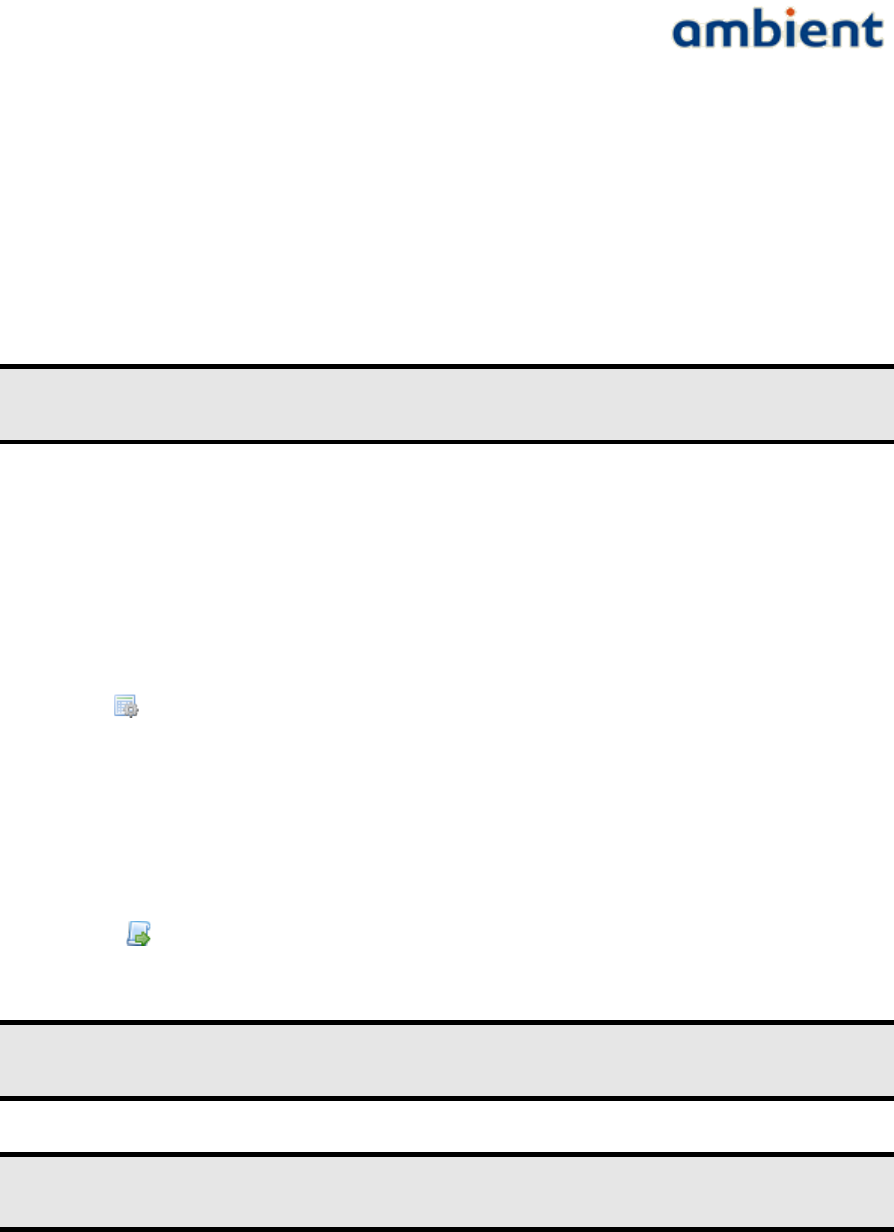
4.Press the following button: The time and date set panel appears.
5.Press “Synchronize” to copy the date and time settings from the PC to the Gateway GW3000.
It can take a few minutes before the time and date settings have propagated to all devices in
the Series 3000 network12.
6.Press “Close” to confirm the time and date settings.
6.3 Deployment
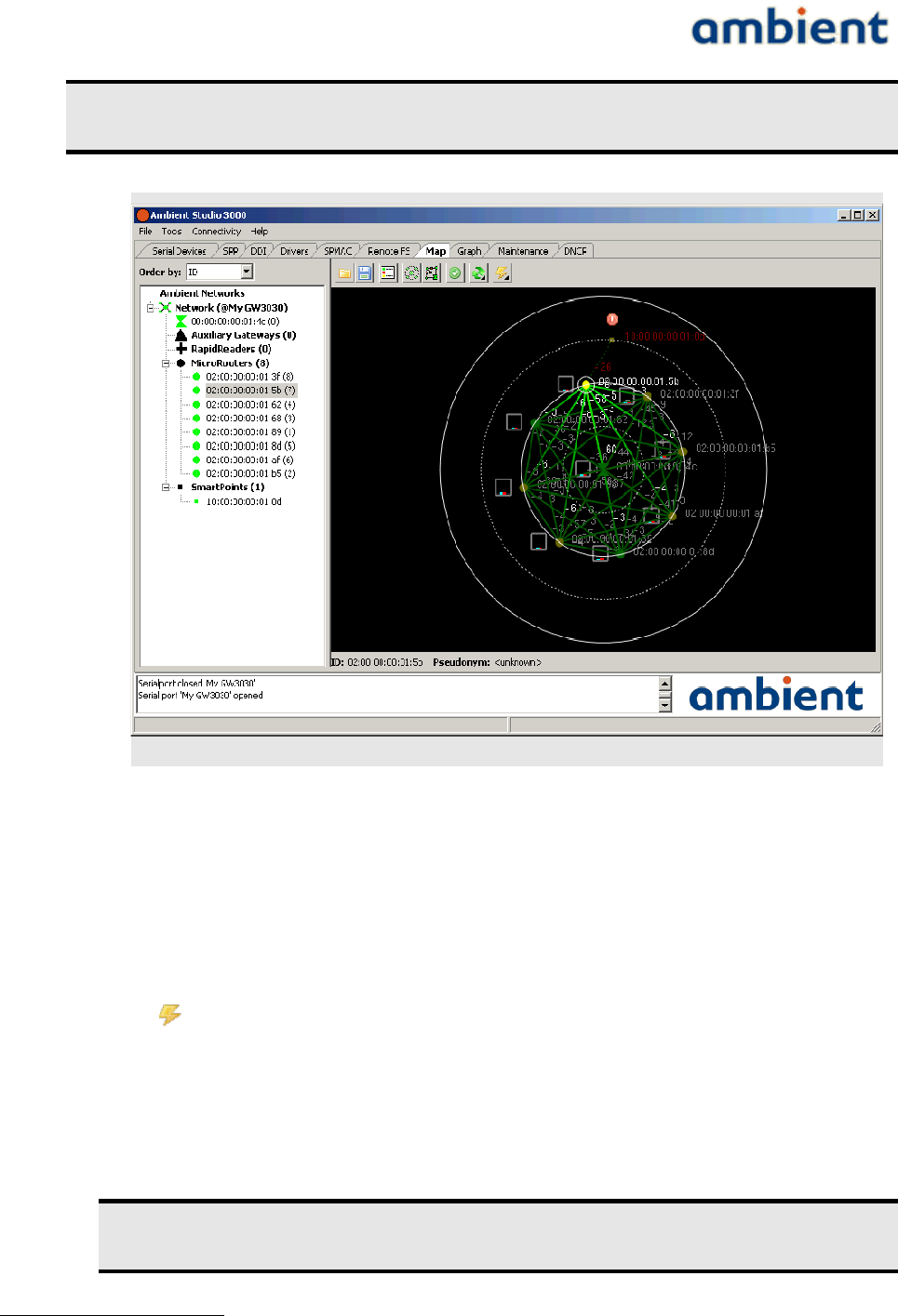
Ambient Studio provides convenient ways of visualizing your Series 3000 network deployment by
means of the Map View. It provides an overview of the devices of your network and how they are
interconnected. Especially the connectivity of the individual devices is of importance as typical
ranges of devices vary between different environments.
Note: Chapter 7 provides useful hints on how to deploy the Series 3000 network.
In Ambient Studio, select the “Map” tab to visualize your deployment. The view can be used for the
following:
•Check if all your devices join your network – The left side of the Ambient Studio window
shows a list of all devices present in your network. The view is automatically updated when
devices join or leave the network.
1 By pressing the option button, Ambient Studio can be configured such way that it can synchronize the gateway time automatically.
2 SmartPoints will use the new time after the first succefull communication
29/73 Ambient Systems B.V.
User Manual
3000 SERIES 3rd GENERATION ACTIVE RFID
Note: It can take up to two hours1 before all SmartPoints report in new
deployments. MicroRouters needs to be powered by mains before they report.
•Check if all nodes have acceptable link qualities – You can check link qualities between nodes
by looking at the colouring of nodes and lines between them. See Chapter 6 for more
information on deploying a network. (By pressing the configuration button, various options
exists in order to hide certain lines).
•Check networking status – You can visually check if devices are congested and whether you
need to deploy additional devices to remove bottlenecks from your deployment.
•Check power status – You can visually check the power status of all devices. You can remotely
inspect if devices operate on batteries and if the batteries have sufficient capacity. Press
to view the information. Since the information is retrieved from the network, it can
take a while before the information is displayed.
If you select a device in the list, it will be highlighted in the map and information about the
device is displayed. You can obtain detailed information about a particular device by selecting it
in the list and right click on it. Choose the “Properties” option. A panel with detailed
information appears (or right click a node in the map view). Press “OK” to dismiss the panel.
Wait until all devices appear in the Map View before continuing network
configuration.
1 Assuming that there is no package loss of the SmartPoint
30/73 Ambient Systems B.V.
Illustration 16: Circular network view
User Manual
3000 SERIES 3rd GENERATION ACTIVE RFID
6.4 Enabling built-in backup batteries
When Gateways and MicroRouters are shipped, their backup battery has been disabled. You have to
enable the backup battery to make sure that the Series 3000 network remains functional during short
power shortage.
You need to perform this action only once per Gateway or MicroRouter.
Note: The backup battery must be enabled once to keep the network functional
during short mains outages.
To enable the backup battery:
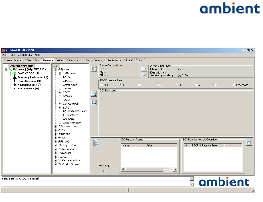
1.Select the “Drivers” tab in Ambient Studio.
2.Select a Gateway or a MicroRouter from the device list (make sure DDIP level 2 is selected)
3.Select the “Power” from the DDI tree view (Illustration 18).
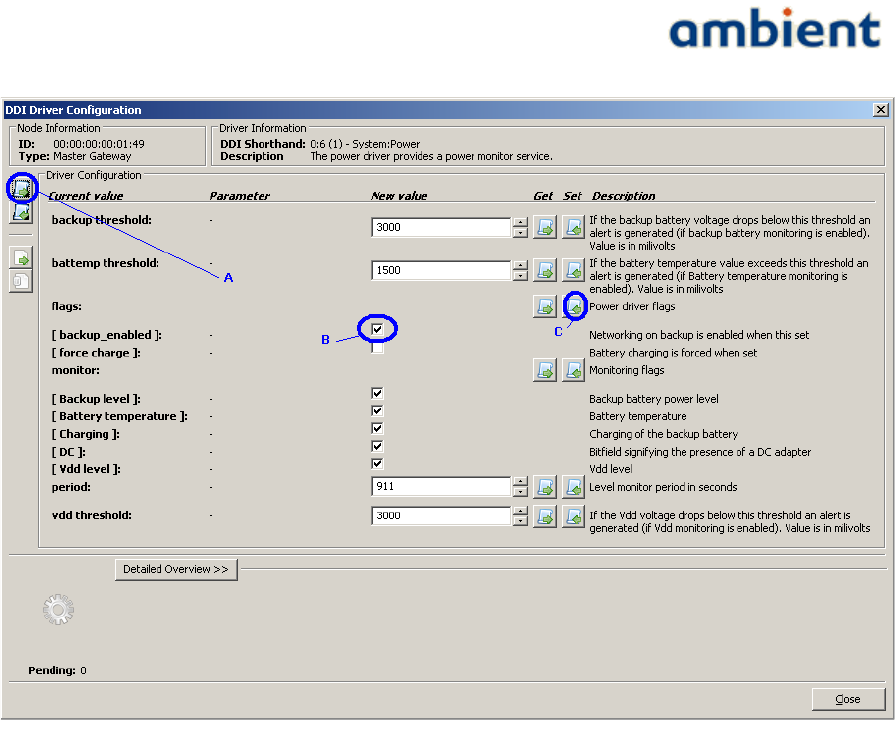
4.Press to configure the power driver. The power driver configuration panel appears
(Illustration 17)
5.To download the current configuration settings press download driver button, marked as A.
in Illustration 17. Wait until “Pending” returns to 0 and the values in the view are updated.
6.Set the check mark at “[backup_enabled]” (B.) under “flags”.
7.Press in front of “Power driver flags” at C. Wait until “Pending” returns to 0. The
backup battery has now been enabled for the selected device.
Tip: In the Ambient Studio Series 3000 User Manual is described how the
configurations of multiple devices can be set at once.
Note: The panels might look different in your network, depending on your
configuration and available DDI drivers.
6.5 localization
localization is discussed in the localization white paper which can be obtained on our support
31/73 Ambient Systems B.V.
User Manual
3000 SERIES 3rd GENERATION ACTIVE RFID
website. Please take a look at this document for more detailed information. The text in this section
discusses only localization set-up.
6.5.1 localization deployment.
Deploying a 3000 Series localization network is similar in many aspects to deploying a regular
network for e.g. temperature monitoring or inventory management. When deploying a network with
localization functionality enabled, you should try and take into account a few more aspects than you
would normally do for a monitoring deployment. In general, deploying localization infrastructure is
done by performing the following steps:
1. Place the Gateway and MicroRouters in the localization environment.
2. Configure the locations of the Gateway and the MicroRouters.
3. Configure and enable localization parameters on the SmartPoints.
In the following subsections we cover the aforementioned steps in more detail.
32/73 Ambient Systems B.V.
Illustration 17: tree view of available drivers
User Manual
3000 SERIES 3rd GENERATION ACTIVE RFID
6.5.2 Place Gateway and MicroRouters
First you need to physically place and mount the Gateway and the MicroRouters in the localization
environment. Take into account the following additional considerations:
●SmartPoints have to be surrounded by Gateways and MicroRouters otherwise localization
will not work correctly. Placing the Gateways and MicroRouters at the corners and along
the borders of the localization area and evenly distributed throughout the deployment area
will ensure this.
●Ensure that SmartPoints are always in range of at least one infrastructure device in order to
obtain a position estimate and communicate with the network. However, the more
infrastructure devices you hear, the better your position estimate.
In order to get the BEST localization performance:
●Place the Gateway and MicroRouters in a uniform distributed grid.
●Place the Gateway and MicroRouters in such a fashion that they have an optimal line of
sight with SmartPoints.
●Place the Gateway and MicroRouters at the same height.
●Mount SmartPoints at the same height as the MicroRouters (if possible, else not close to the
floor, ceiling, preferable in the middle).
●Ensure that the antennas of the Gateway, MicroRouters and SmartPoints have a similar
orientation.
33/73 Ambient Systems B.V.
Illustration 18: Power driver of Gateway/Microrouter

User Manual
3000 SERIES 3rd GENERATION ACTIVE RFID
Ideally this means that antennas of GWs and MRs are oriented vertically, and that
SmartPoints are mounted upright, i.e. when holding the SmartPoint in one hand with your
arm outstretched, you should be able to correctly read the Ambient logo.
●Ensure that SmartPoints are in range of at least four infrastructure devices.
6.5.3 Set coordinates of Gateway & MicroRouters
After you have deployed your 3000 Series network you need to configure the positions of the
Gateway and MicroRouters in/with Ambient Studio so they match the physical real-life position of
the devices in the deployment area. Please make sure you read the 3000 Series Ambient Studio User
Manual for detailed information. This requires the following steps:
1. In Ambient Studio, navigate to the 'map' tab.
2. Load a map of the localization area.
3. Drag Gateway and MicroRouters to coordinates on the map that match their real-life
positions and send it to the device by pressing the 'Set Position' button (red flag). Make sure
their real-life position matches the position in Ambient Studio as best as possible.
4. Optionally, you can set the position of the device by using the Node Information dialogue:
right-click on any device to open the dialogue.
1. Navigate to the 'Localization' tab.
2. Fill in the real-life position of the device in the provided fields.
3. Press the 'Set Position' button to commit the position to the device.
The accuracy of the 3000 Series localization system depends on the MicroRouter density. For
example, for room level localization accuracy the MicroRouters are best positioned in each room, or
every other room. Also, you should take care when dealing with support walls which often
surround (emergency) staircases. It is advised to place additional MicroRouters in such areas.
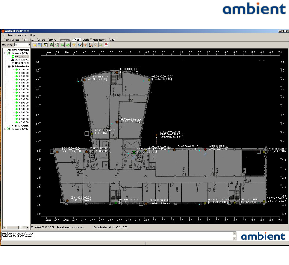
Illustration 19 shows the 'Map' tab of Ambient Studio with an example deployment:
●The white figure on the background is the loaded floor plan.
●The circles represent the MicroRouters.
For detailed information about Ambient Studio, please read the 3000 Series Ambient Studio
User Manual.
34/73 Ambient Systems B.V.
User Manual
3000 SERIES 3rd GENERATION ACTIVE RFID
6.5.4 Enable localization of SmartPoints
In order to enable SmartPoints to locate themselves, you have to activate their location engine driver.
The 'Drivers' tab of Ambient Studio can be used to do that. Perform the following steps to configure
the localization engine:
1. In the left network tree control select a SmartPoint.
2. In the second DDI tree control navigate to driver class '13:Localization' and expand the field.
3. Navigate to driver '2:Engine'.
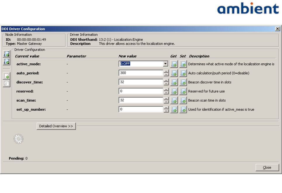
4. Press the 'Configure Driver' button to the upper right. A dialogue will open. See Illustration
20
5. Fill in the appropriate driver parameters (see explanation below).
6. Set the configuration of the engine by pressing the 'Set Full Configuration of Driver'
7. button to the left side of the dialogue. Wait for the request to complete: the icon to the lower
left should indicate a green 'OK' icon.
35/73 Ambient Systems B.V.
Illustration 19: Map tab of Ambient Studio with example floor plan and infrastructure devices
User Manual
3000 SERIES 3rd GENERATION ACTIVE RFID
The parameters of the localization engine consists of the following:
●active_mode
Selects whether localisation is switched off, or the position or measurement mode is selected.
Default value: off.
○Position
This parameter enables the SmartPoint to perform RSS measurements for centralized
calculation. Only X,Y,Z and timestamp values are pushed.
○Measurement
This parameter enables the SmartPoint to perform RSS measurements for centralized
calculation, debug or research purposes. The raw RSS measurements are pushed along
with the location (X,Y,Z, timestamp)
●auto_period
This parameter represents the period in seconds in which the SmartPoint locates itself or
performs RSS measurements. Decreasing this parameter increases the energy consumption.
The minimum value of auto_period is set to 10 seconds.
Default value: 300.
●discover_time
This parameter represents the time the Smartpoint searches for a 3000 Series network.
Default value: 32.
●scan_time
This parameter represents the time the SmartPoint listens to MicroRouters for obtaining
RSSI information. Increasing this parameter increases the energy consumption of the
SmartPoint.
36/73 Ambient Systems B.V.
Illustration 20: Setting parameters of SmartPoint Localization Engine in Ambient Studio

User Manual
3000 SERIES 3rd GENERATION ACTIVE RFID
Default value: 32.
●setup_number
This parameter is used for identification purposes when performing RSS measurements. The
setup number can be used to identify, for example, groups of SmartPoints based on their
configuration. In normal circumstances you will not use this parameter at all.
Default value: 0.
Once you have enabled localization, you will immediately start receiving position updates from
SmartPoints. You can use Ambient Studio to visualize this information. In the 'map' tab in Ambient
Studio the SmartPoints are displayed. When you select the 'User View' option Gateways,
MicroRouters and SmartPoints are displayed with their virtual coordinates. If any new position
information is received, the SmartPoint will be redrawn to resemble its location in real-life.
6.6 DNCP
Dynamic Network Configuration protocol, or DNCP for short is the protocol for assigning slots to
the MicroRouters. A MicroRouters needs at least one slot for proper operation. This protocol is
hosted by the GateWay. With the DNCP driver, slots can be made static and multiple slots can be
assigned to MicroRouters. It is not advised to change device without consulting Ambient Systems
support. Contact support@ambient-systems.net for more information.
6.7 Security
Contact support@ambient-systems.net regarding the security features of the 3000 Series.
6.8 Temperature monitoring
SmartPoints SP3000 have built-in temperature sensors that sense the ambient temperature of the
device. The sensors have been pre-calibrated in order to provide accurate temperature readings. The
behaviour of the temperature monitoring capabilities of the SP3000 can be controlled through the
Temperature DDI driver. This section describes how the temperature driver can be configured to
meet your requirements. By default, SPs report temperature once every 5 minutes.
The following alerts are generated by the temperature DDI driver:
●Temperature range: An alert range can be set and an alert will be generated when the
temperature is in the alert range. Or an alert can be generated when temperature is outside
the range. E.g. food needs to be stored between +2°C and +7°C. When temperature is lower
than +2°C OR higher than +7°C, an alert should be given.
●Temperature change: An alert can be generated when the temperature changes more rapid
than a given range. E.g. a greenhouse is heated to +30°C. Due to fluctuations of the heating
system, the temperature drifts up to 3°C in 5 minutes, but when a door is left open, the
temperature changes more than 0°C to 3°C in 5 minutes and an alert should be generated.
●Combination: Range and change alerts can be combined. E.g. food needs to be stored
between +2°C and +7°C and temperature might not fluctuate more than 2°C per 5 minutes.
The following sections explain the two types of alarms in more detail.
37/73 Ambient Systems B.V.
User Manual
3000 SERIES 3rd GENERATION ACTIVE RFID
6.8.1 Range alarms
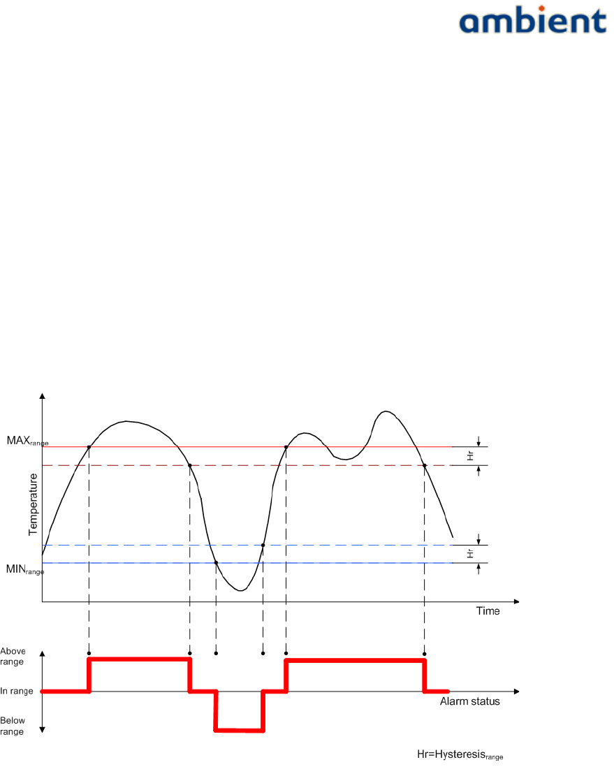
Range alarms are generated based on the absolute measured temperature. The measured
temperature is compared to the range specified by MINrange and MAXrange. If the temperature is not
less than MINrange and not greater than MAXrange the temperature is in range. If the temperature is less
than MINrange it is below range and if it is greater than MAXrange it is above range. A temperature driver
can be configured to generate alarms if the temperature is within range or outside (below or above)
range.
The range also has a hysteresis value Hr. This value is relative to the MINrange and MAXrange
thresholds. In the case that the temperature is outside the specified range it must change at least Hr
degrees beyond the MINrange or MAXrange threshold to be considered in range again. Having this
hysteresis can prevent rapid change in alarm status when there is a small fluctuation in temperature
around a threshold value.
The values for the range alarm driver settings are expressed in degrees Celsius (°C).
The following picture depicts the behaviour of the range alarm for a specific temperature curve.
6.8.2 Change alarms
Change alarms are generated by the amount of change in temperature between two sample periods.
A temperature driver will sample its sensor with a configured period. The change in temperature
between two samples is compared to the MINchange and MAXchange thresholds. If the temperature is
decreased more than MINchange it is below the change range, if it is increased more than MAXchange it is
above the change range. Otherwise the temperature change is in range.
Like with the range alarm a temperature driver can be configured to send an alarm if the
temperature change is within range or outside (above or below) range.
38/73 Ambient Systems B.V.
Illustration 21: Temperature range alarms example
User Manual
3000 SERIES 3rd GENERATION ACTIVE RFID
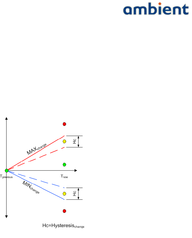
The change range has a hysteresis value Hc. This value is relative to the MINchange and MAXchange
thresholds. In the case that the temperature change was outside the specified range the change of
temperature of the next sample must be at least Hc degrees beyond the MINchange or MAXchange
threshold to be considered in range again. Having this hysteresis can prevent rapid change in alarm
status when there is a small fluctuation in temperature change around the threshold value.
The values for the change alarm driver settings are expressed as degrees Celsius per sample period.
The following graph (Illustration 22) depicts the generic behaviour of the change alarm mechanism.
The graph shows the time interval between two samples. The sample at Tnow is tested for its position
relative to the value of the MAXchange and MINchange lines at Tnow.
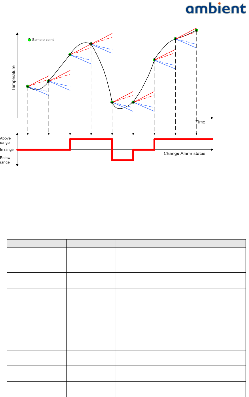
The following graph (Illustration 23) depicts the behaviour of the change alarm mechanism for a
specific temperature curve. In this case alarms are configured to be generated when the temperature
is outside the specified range. For every sample (the green dot) the generic picture above is drawn to
visualize the change relative to the chosen thresholds.
39/73 Ambient Systems B.V.
Illustration 22: Hysteresis
User Manual
3000 SERIES 3rd GENERATION ACTIVE RFID
6.8.3 Configuration
Ambient Studio allows you to configure (driver panel) the following parameters:
field min max default description
sample period 10 65535 300 Sample period in seconds
send period 10 65535 300 Set the sending periodic of automatic pushing of
readings
Alarm period 10 65535 300 The period with which temperatures are sent in case
of an alarm (in seconds)
Behaviour - - 0 Determines the behaviour of alarms and periods. See
Ambient Studio Temperature Driver Configuration
Panel for more details.
calibration -128 +127 0 Calibration value of the sensor
range min value -2048 2047 0 Minimum value of the alarm temperature range in
degrees Celsius
range max value -2048 2047 50 Maximum value of the alarm temperature range
degrees Celsius
change range min value -2048 2047 -5 Minimum value of the alarm temperature change
range in degrees Celsius per sample period
change range max value -2048 2047 5 Maximum value of the alarm temperature change
range in degrees Celsius per sample period
hysteresis -2048 +2047 0.5 Hysteresis value of the alarm temperature range in
degrees Celsius
40/73 Ambient Systems B.V.
Illustration 23: Temperature change alarm example

User Manual
3000 SERIES 3rd GENERATION ACTIVE RFID
change hysteresis -2048 +2047 1.0 Hysteresis value of the alarm temperature change
range in degrees Celsius per sample period
6.9 Logging and flushing
In dynamic environments where SmartPoints enter and leave the network, the log and flush drivers
can be used to retrieve all 'missing' samples/measurements. For example, when a SmartPoint is
attached to a truck, all temperature measurements are lost when the SmartPoint is not in range of
the network. With logging and flushing these measurements can be restored.
In order to describe how to set-up the logging and flushing functionality, a short introduction of
DDI (Device Driver Interface) is required. For detailed DDI information, please take a look at the
DDI specification which can be obtained from the Ambient Systems Support website.
DDI has the following operations:
1. Request/return. A device can sent a request message to a certain driver, the receiver checks
validity, executes the function and the result of the function is sent in return.
2. Invoke. A device can sent an invoke message to a certain driver, the receiver checks validity,
executes the function. No return is sent.
3. Push. Certain drivers, like the temperature driver on the SmartPoint can sample the
temperature at certain intervals and 'push' this message into the network.
4. Error. The error message type is used whenever a request or invoke is issued and the ddi call
is invalid (e.g it doe not exist or the payload is wrong).
5. Alert. Certain drivers, like the temperature driver on the SmartPoint can sample the
temperature at certain intervals and 'push' this message into the network. However if the
alarm driver of, in this case the temperature driver is configured as well and there is an
alarm situation, the message type is not a push message but an alert message. Alert
messages have higher priority and travel therefore faster through the network.
6. FlushPush. This message type is use to indicate that a message is a measurement from the
past and the original message type was a push.
7. FlushAlert. This message type is use to indicate that a message is a measurement from the
past and the original message type was an alert.
Only push and alert messages can be logged (and flushed). Please note that the payload of the flush
(alert) and flushpush (flushalert) is exactly the same. Only the message type is changed1.
6.9.1 Configuration of the log and flush driver
In release 1.0 of the 3000 series, two drivers can be logged in parallel. These log is stored in the log
file log_0 and log_1. The maximum amount of samples which can be logged is configurable, 2048
samples per log file is the upper limit.
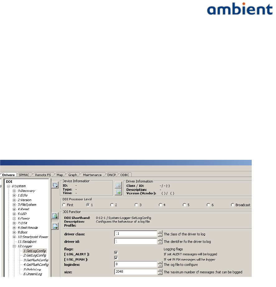
In Ambient Studio, select a SmartPoint in the tree view of the Driver panel. Unfold the the available
drivers and select 0:System, 12:Logger and 1:SetLogConfig. Select whether log-index 0 or 1 has to be
used, the size of the log file and select which driver has to be logged. For the temperature driver this
1 the DDI-timestamp as this is attached to sample when receiving it in Ambient Studio
41/73 Ambient Systems B.V.
User Manual
3000 SERIES 3rd GENERATION ACTIVE RFID
is 11:1. Select whether only pushes, alerts or both message types have to be logged. This is
illustrated in Illustration 24.
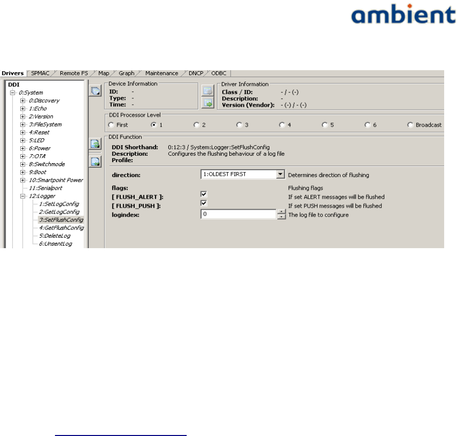
Secondly, the flush functionality has to be configured. Select 0:System, 12:Logger and
1:SetFlushConfig for the same SmartPoint. Select direction 'oldest first', select logindex 0 and select
flush_push and flush_alert. This is illustrated in Illustration 25.
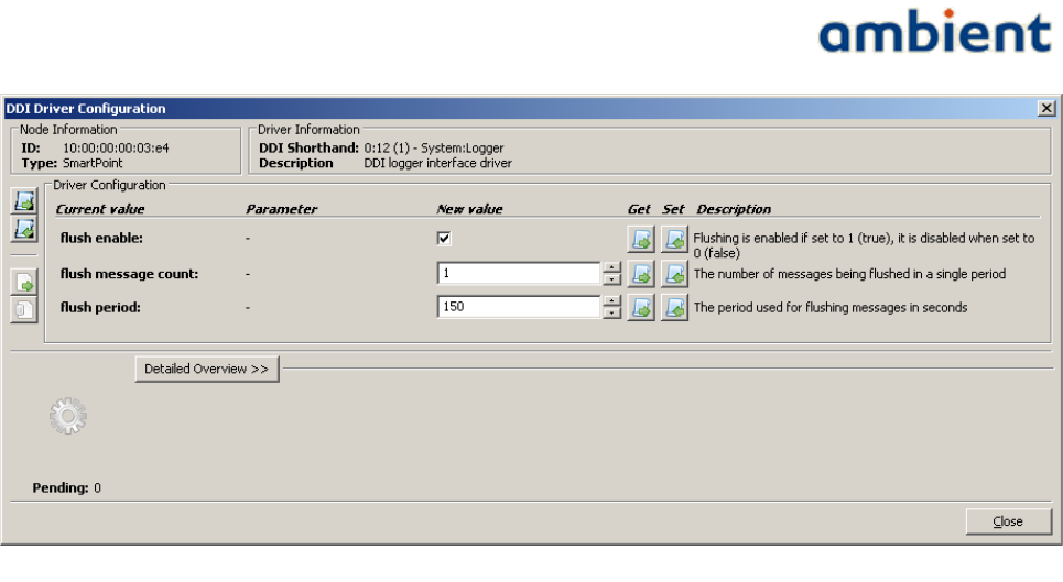
Third, flushing has to be enabled on the SmartPoint, this can be done by pressing the configure
driver button (of driver 0:System, 12:Logger). Select flush enable. The rate of flushing is defined as
M messages per period P, where M and P are adjustable at runtime. So each period P the flushing
mechanism will try to send at most M messages. For now the default values are M=1 and P=150. P is
expressed in seconds. If flushing is enabled for more than one function; F > 1, then P is divided by F
and in each sub period M messages from a single function are flushed. So effectively each function is
still flushed at rate M/P but the network load is spread over time per function. The configuration is
illustrated in Illustration 26.
42/73 Ambient Systems B.V.
Illustration 24: Setting the log driver
User Manual
3000 SERIES 3rd GENERATION ACTIVE RFID
6.10 Coexisting Networks
At this moment two (or more) networks cannot run at the same physical location. Both networks
will use the same frequency. Radio messages will collide and routers will (likely) lose their
connection with the gateway. The delivery rate of the SmartPoint will likely drop and it might be
possible that messages are coming in via both(all) gateways.
Therefore, make sure that there is maximum one GateWay switched on a single location.
Contact support@ambient-systems.net for more information.
43/73 Ambient Systems B.V.
Illustration 25: Setting the flush driver
User Manual
3000 SERIES 3rd GENERATION ACTIVE RFID
44/73 Ambient Systems B.V.
Illustration 26: Configuration of the flush driver

User Manual
3000 SERIES 3rd GENERATION ACTIVE RFID
7 Deployment
As with every wireless technology, deploying the devices physically in the environment requires
considerations of environmental parameters like thickness and material of walls, metal objects, glass
(coated) windows, people moving around, environmental conditions such as temperature and
humidity, doors; they all influence radio wave propagation. WSNs are not an exception to this rule.
However, with a bit of planning, some background knowledge about multi-hop networks it
shouldn't take long to deploy an Ambient Network.
7.1 Preparations
It is important to deploy the network well prepared; take your time. It is vital that, prior to
deployment, detailed site information is obtained; where possible, obtain maps or blueprints with
detailed information (AC power outlets, supporting versus non-supporting walls, etc.). If no maps
are available, draw one by exploring the site before deploying a single node.
Find available AC power outlets and also mark these down on the map. Make sure that these outlets
are active for 24 hours every day and not included in nightly energy savings schemes. Some outlets
are better suited than others; outlets above ceiling plates (in office environments) are preferable, such
that people won’t use the outlet for other purposes and the MR could be disconnected. Although an
Ambient infrastructure has a rechargeable backup power source, they need to be recharged
periodically. If this situation arises, confirm that the outlet is active long enough to charge the
backup power source.
Identify possible problematic structures, for example walls with a lot of metal, strengthened glass,
elevator shafts and so forth. Also identify any equipment that could potentially generate RF
signals/interference.
The following list summarizes the steps that should ensure you have made the appropriate
preparations;
1. Obtain detailed blueprints / maps of the target site (see example in Illustration 32)
2. Mark down AC outlets
3. Mark down any building materials or objects that could reduce the range of the nodes, such
as thick concrete walls, windows, metal doors, electrical equipment, and so forth
4. Make sure you are aware to the best of your knowledge of other wireless devices in the
target environment that use the 2.4 GHz band, such as cordless phones, WiFi access points,
IEEE 802.15.4 or ZigBee® enabled networks, and so forth. These devices may interfere with
the Ambient Systems 3000 series or the Ambient Systems 3000 series may interference on
these wireless devices in the 2.4 GHz band. If performance loss is noted, please contact
support@ambient-systems.net.
Always make a Deployment Plan before deployment!
Always obtain Site Information before making a Deployment Plan!
45/73 Ambient Systems B.V.
User Manual
3000 SERIES 3rd GENERATION ACTIVE RFID
7.2 Deployment Planning
Although an Ambient network is built up from the GW outward, a deployment planning is built up
the other way around; starting from the SPs. As SPs have a shorter range than infrastructure nodes,
they determine the positions where infrastructure nodes should be placed. In order for SPs to
communicate with an MR, it needs to be in range of the MR.
Mark the locations on the sitemap that require network coverage, i.e. the locations where you want
to deploy SPs. SPs are deployed at those locations where you wish to measure environmental
parameters. If you are using the Real Time Location System (RTLS) functionality of the SPs, mark the
area where the SPs will need to be located.
Having the SPs marked down and the SP location area marked down, you can now use their typical
radio coverage to identify the areas where you need to place MRs. Draw circles around each SP. Use
as diameter typical value of 15 meter. Each SP should be in range of at least 1 MR or the GW, but
preferably more to ensure good connectivity. The areas on the map that are covered by several
circles are good locations to place MRs. As a rule of thumb, it is preferable for every SP to be in range
of at least 3 Infrastructure nodes. The SP has multiple paths to the gateway and there is enough
redundancy in case one router is congested or off-line due to whatever reason.
For larger sites it makes sense to perform some range tests prior to planning the installations.
Deployment tooling can be used for this purpose. Contact support@ambient-systems.net for more
information about deployment tools.
Ensure that every SP is always in range of at least 3-4 Infrastructure Nodes
Print the Deployment Sheets part 1 and 21 to keep track of the deployed nodes. During the process of
planning your deployment, write down the unique ID of the GW/MR/SP and its respective location
on the map as well as a short description of the area in which it is placed, for example:
N o d e T y p e N o d e I D D e s c r i p t i o n
MicroRouter 02:00:00:12:34:56 Above the door, placed in the centre, powered using
the AC outlet from the ceiling lighting
Now after having collected the maps and pictures and having marked all important locations on it,
we are ready to make a first Infrastructure deployment plan.
Start with placing the Gateway preferably somewhere in the centre of the environment; this is critical
to the structure of your network. If you place the Gateway at the centre of the network, you will have
less hop counts and thus less latency; if you place the Gateway at the corner of the network, you will
introduce higher hop counts and as a result have more latency and increased the probability of
creating bottlenecks.
Now, using the positions and areas of the SP, place an MR near an AC outlet in areas that are in
range of the SPs. On a separate map, place the MRs at exactly the same locations. Now try to make
an estimation whether the network is well connected by drawing circles around the MR based on
their typical radio range. Ensure that each MR is in range of at least 2 other MRs and that there is
1 The Deployment sheets part 1 and 2 accompany this user manual as separate documents.
46/73 Ambient Systems B.V.
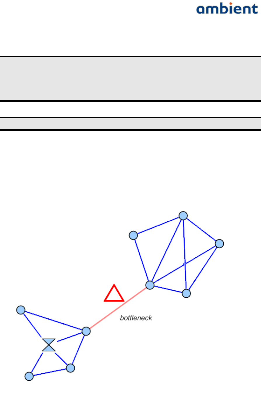
User Manual
3000 SERIES 3rd GENERATION ACTIVE RFID
always a path to the GW for each MR. Ensure that the GW has at least 3 hop 1 connections to reduce
the chance of bottlenecks. Plan additional MRs between MRs that are expected to be too far apart.
Always leave some margin for reduced radio range due to changes in your
environment when making a Deployment Plan!
Always ensure that each MR is in range of at least 2 other MRs with the same or
lower expected hop count!
Always ensure that each GW has at least 3 hop 1 connections!
7.2.1 Infrastructure Bottlenecks
In each deployment, there is a chance of introducing so-called bottlenecks. Metaphorically speaking
bottlenecks are a section of a path with a carrying capacity substantially below that characterising
other sections of the same route. This is often a single connection between two MRs that separate
larger portions of a network (see Illustration 27).
47/73 Ambient Systems B.V.
Illustration 27: Example Bottleneck situation

User Manual
3000 SERIES 3rd GENERATION ACTIVE RFID
The aforementioned bottleneck is a typical Infrastructure bottleneck and can easily be avoided by
placing additional MRs around the problem area.
Avoid Infrastructure bottlenecks by all means.
7.2.2 SP Load Bottleneck
Another type of bottleneck can be introduced by SPs, but these are a bit harder to find and depend
heavily on the configuration of an SP. By default, a SP3000 will send a message every 5 minutes. By
default, a GW and MR can handle 2 SP interactions per second1. As a result you should then be able
to place 60*5*2 = 600 SPs around a single Infrastructure node. However, packet loss can occur, SPs
can wake up at the same time, and so forth. As a rule-of-thumb, it is advisable not to exceed the load
of a GW or MR with more than 50 SPs in its range. Your Infrastructure deployment needs to
incorporate this SP load and provide enough bandwidth to handle the SP payload. A way of
determining the network load is described below.
We determine the load of a GW or MR, indicated as the 'SP Load', by determining how many SPs are
in range of an Infrastructure node. With this approach we assume that every SP is configured
similarly, i.e. all SPs transmit the same number of packets within the same time period. A single SP
provides an SP Load of 1. If an SP is in range of more Infrastructure nodes, we calculate the load by
dividing 1 by the number of Infrastructure nodes in its range. We can now determine the SP load of
an infrastructure node by summing the SP loads of the SPs in its range. For the Infrastructure nodes
we can now determine an accumulative load by summing all the SP loads of Infrastructure nodes that
are one hop further away. As with the SPs, depending on the number of Infrastructure nodes in
range the SP load is divided by the number of Infrastructure nodes that are one hop closer to the GW
(see Illustration 28).
1 This can be change to 4 by configuring the appropriate driver, driver network:DNCP
48/73 Ambient Systems B.V.
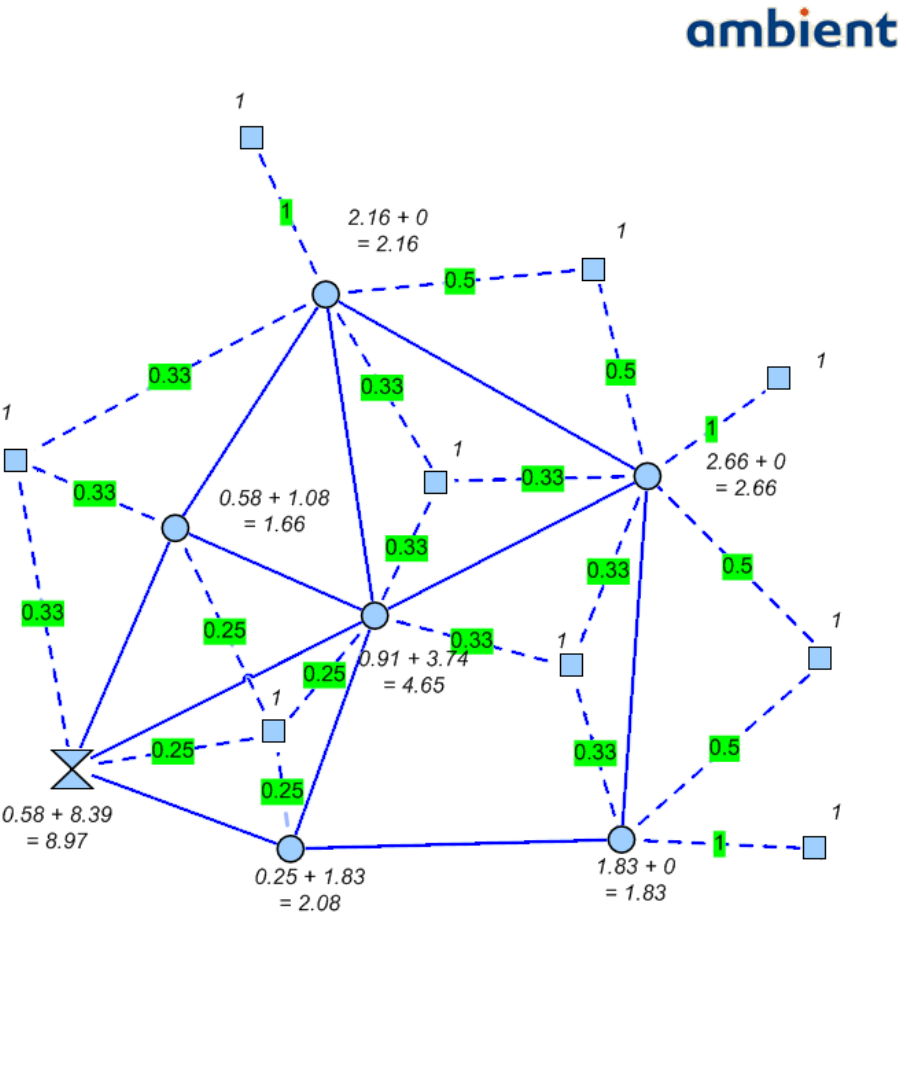
User Manual
3000 SERIES 3rd GENERATION ACTIVE RFID
Now using the default SP values, a SP load of 1 means '1 message per 5 minutes'. If we convert this
to the number of messages per second, we get the value 1 / (5 * 60) = 0.003 messages per second. A
single MR-SP link is capable of handling 2 messages per second by default. However a single MR-
MR links is capable of handling 1 message per second. This results in a SP load capability of 1 * 5 * 60
= 300. The network itself consumes some of this bandwidth to establish and maintain the network
coherence and layout. Also, packet loss or retries can occur. As a rule of thumb, roughly 10% of the
available bandwidth is consumed by internal use and packet loss or retries, assuming stable
connections between Infrastructure nodes. The further away an MR is from the GW (in hops), the
more bandwidth is consumed by the intermediate MRs. As a result, an Infrastructure node is capable
of handling a SP load of 0.90 * 300 = 270. If the SP load that you calculated gets close to this number,
you should place an additional MR to increase the available bandwidth.
49/73 Ambient Systems B.V.
Illustration 28: Example SP Load calculations, with every SP default at load 1, every
Infrastructure node combination of its own SP load and additional accumulative SP
Load

User Manual
3000 SERIES 3rd GENERATION ACTIVE RFID
It should be noted, however, that there is a chance that SPs do not consume the beacons provided by
the Infrastructure nodes in a evenly distributed way, so some margin for error needs to be taken
into account.
Calculate the accumulative SP load to identify potential congestion bottlenecks!
If an accumulative SP Load nears the maximum network bandwidth, place
additional Infrastructure nodes to introduce additional bandwidth!
7.3 Deployment Execution
After the Deployment Plan has been set up, it is time to start deploying the nodes according to the
plan. Every deployment starts with the GW since a network can not exist without it. Then, after the
Gateway has been set up, the MRs are added to the network. Finally, after the Infrastructure has
been deployed, we place the SPs at their target locations.
7.3.1 Mounting the Gateway / MicroRouter
Generally the GW and MR should be mounted such that the swivel antenna is always in vertical
position. This ensures the same polarization for all the antennas and in consequence best
connectivity. The above statement holds for both indoor and outdoor networks. Also, all MRs and
GWs should preferably be placed at the same height above the ground. For best radio performance
1.5 meters above the ground or higher but not closer than 1 meter to the ceiling.
Ensure all antennas are in vertical position for best radio performance.
As the GW and MR comes with a swivel antenna there are a number of considerations for placing
the MR and GW. Always try to place the GW or MR as far as possible from surrounding objects as
possible, such as large metallic objects, walls, pylons or other obstacles. Placing the antenna too
close to objects will alter the radiation efficiency so that less power is radiated into free space,
effectively reducing the range of the GW and/or MR.
Mount the GW and MR in such a way that its antenna has a good clearance. This ensures the best
performances and radiation efficiency. Keep in mind to avoid placing the antenna too close to
corners of the room. Mount the GWs and MRs at a height such that it radiates above most obstacles
such as metal cabinets for maximum performance.
Once you have selected a good position and orientation for mounting a GW or MR, use screws and a
screwdriver1 to fix it in place. Then connect the node to the power using the AC adapter and wait for
it the go through the right sequence of the start-up procedure by observing its LEDs. The LED2
sequences can be found in Illustration 29.
1 Only use screws of 5 mm diameter or thinner. If you use screws that are thicker, you risk damaging the enclosure.
2 When printing in grey colours, the led colours are from left to right, blue, green, orange and red.
50/73 Ambient Systems B.V.
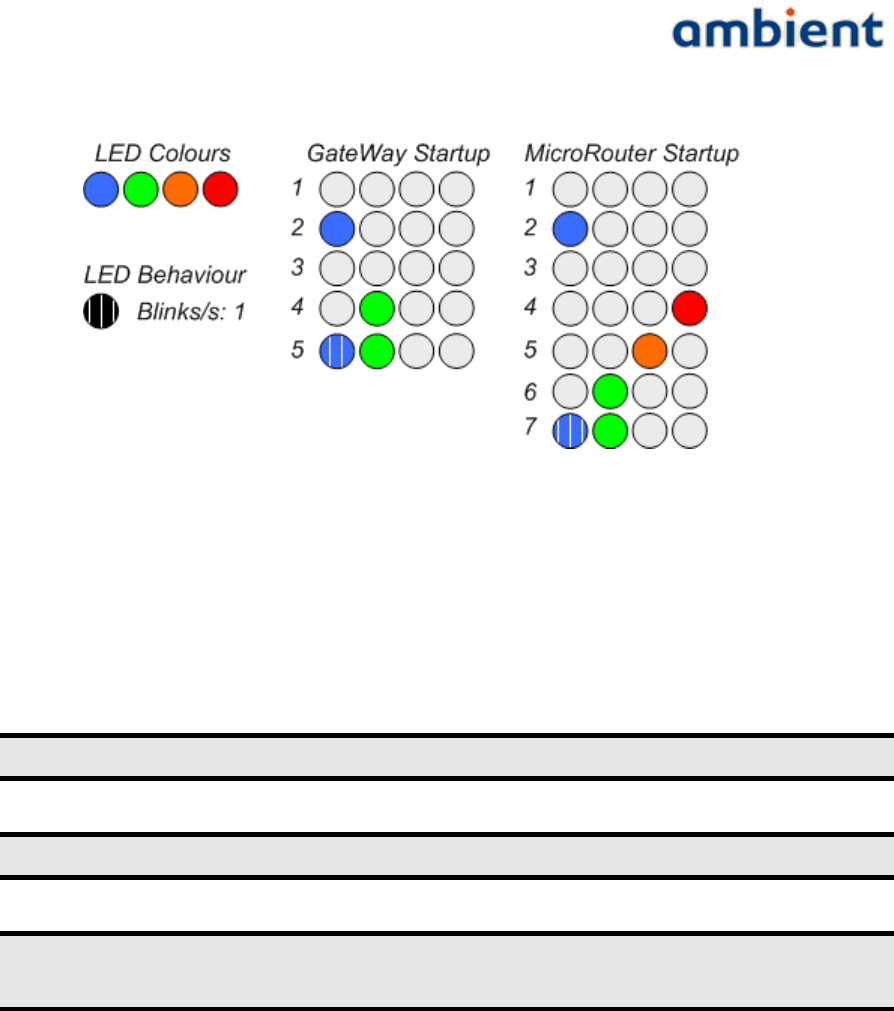
User Manual
3000 SERIES 3rd GENERATION ACTIVE RFID
If the MR remains in start up phase 4, it means that it does not hear any network. Ensure that the
SMA antenna is fitted correctly and that you are within range of another active node (e.g. the GW). If
the MR remains in start up phase 5 and then goes back to 4, it means that it did hear a network, but
could not join. This can be due to various reasons. One possibility is that it can not obtain a good link
to the nearest active Infrastructure node. Try a different position closer to the nearest active
Infrastructure node and retry the procedure.
Always place the GW and MR as far away from obstacles as possible!
Prevent placing GWs and MRs in corners of ceilings and walls!
When placing GWs and MRs high on walls and ceilings, ensure you have taken
all safety measures possible!
7.3.2 Mounting a SmartPoint
A SP is mounted easily. There are several ways to go about this: 1) simply place it at the intended
location without fixing it, or 2) use the single-screw hole and fix it by screwing it to the surface of a
wall or object. For different ways of mounting, check our website.
Make sure you use screws of 4 mm or less. If you use screws thicker than that, you can damage the
enclosure.
Once the SP is in place, check with Ambient Studio that it is reporting data and has a good
connection. You can confirm this by navigating to the 'Map' component tab and exploring the tree
view to the left of the screen. Your SP will show up in the tree. Additionally, you can request its link
quality by pushing the button 'Request Link Information from SmartPoints'. It may take some time
for the response to arrive (by default, up to 5 minutes), but now the Map will also show the
51/73 Ambient Systems B.V.
Illustration 29: LED Behaviour for the Gateway and MicroRouter
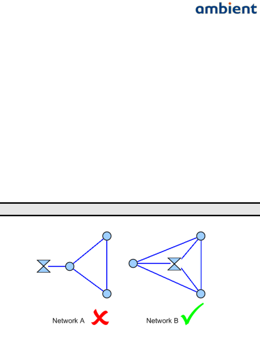
User Manual
3000 SERIES 3rd GENERATION ACTIVE RFID
SmartPoint and its available links to neighbouring Infrastructure nodes. It is placed correctly when
all the indicated RSSI values of all links are -80 or higher (i.e less negative numbers).
7.4 A Few More Pointers
7.4.1 Placing a Gateway
As said before, always start network deployment by placing the GW. The optimal place for the GW
is in the center of the network. A small example in Illustration 30 gives an idea why this is so
important.
In network A the GW is placed at the edge of the network. In this case only one MR has a direct
connection to the GW. The maximum hop count is 2. Furthermore all MRs have only one path
towards the GW. There is a clear bottleneck situation at hop 1.
In network B the GW is placed in the centre. All three MRs have a direct connection to the GW so the
maximum hop count is 1. Also, no direct bottlenecks are visible, though the SP load still needs to be
taken into account.
In general, placing the GW in the middle of a network will minimize the maximum hop-count and it
will result in (at least in the first hop) more paths towards the GW. Latency is reduced and more
bandwidth is available.
Place the Gateway as much in the centre of the network as possible!
7.4.2 Placing a MicroRouter
You will encounter situations where it is very beneficial to place an additional, albeit redundant, MR.
Network stability and coherence, bandwidth, coverage, latency, these are all aspects that can benefit
the network performance greatly by simply adding an additional MR. See Illustration 31 for an
example.
52/73 Ambient Systems B.V.
Illustration 30: Pointer for placing your Gateway
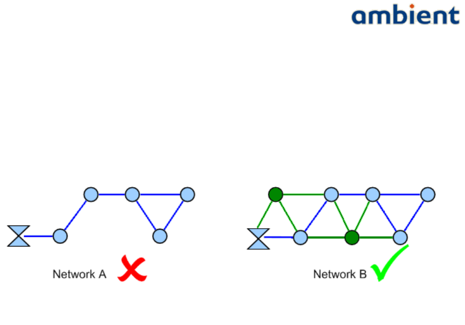
User Manual
3000 SERIES 3rd GENERATION ACTIVE RFID
Network A is a connected network of 5 MRs. It is somewhat shaped as a straight line. However,
there are not many paths available and this network could suffer from bottlenecks. There are in total
6 connections. The GW has only 1 hop 1 connection. There are 3 potential bottlenecks.
In network B two additional MRs are placed at strategic locations. Placing them in such a way you
introduce 7 more connections, bringing the total to 13. The most important improvement is that the
GW now has 2 hop 1 connections. Furthermore, the new situation results in all MRs having at least 2
available connections, and most have more. Also, no direct bottlenecks are visible, though the SP
load still needs to be taken into account.
Of course, preferably in this situation, it is even better to move the gateway to the center of the
network to reduce the hop count.
7.4.3 Avoid Interference
Make sure you place GWs and MRs as far away as possible from appliances such as cordless
telephones, microwaves, televisions and such. This will significantly reduce any interferences that
the appliances might cause since they operate on the same frequency.
7.4.4 Security
Don't give other parties the chance to affect the stability of your networks. Change the default keys
of your nodes prior to deployment so you have a secure network. Please refer to the Ambient Studio
User Manual on how to perform such changes. Make sure you keep track of your network keys!
53/73 Ambient Systems B.V.
Illustration 31: Pointer for placing your MicroRouters

User Manual
3000 SERIES 3rd GENERATION ACTIVE RFID
8 Example Deployments
In this section we address a few example deployments and take you through the necessary steps
required to deploy a network. It can be used as a reference for creating your own Deployment Plan
and the installation after that.
8.1 Example: Office Building
As indicated in the previous sections, we start with an empty map (see Illustration 32). We visually
inspected the site and found plenty of locations for mounting the MRs. Additionally, we checked for
AC power outlets and marked all the outlets on the map (see Illustration 33).
Next, we identified all the locations where we want to place our SPs. For this example we use SP3000
and they need to be placed in every room in order to monitor the different room temperatures. A PC
is connected to the Ethernet and placed centrally in the building and used for connecting to the GW
(see Illustration 34).
Following that, a few locations for placing the MRs are selected, making sure that every SmartPoint
was covered and that most MRs were in range of at least one other MR (see Illustration 35), depicted
with the circles. In this example the range of the MicroRouter-MicroRouter is not depicted.
8.2 Example: Warehouse
The approach for a large warehouse is more or less the same. Please see Illustration 36. In the
warehouse environment there is not always the opportunity to place the gateway in the center of the
building, therefore it will be placed in one of the offices on the right bottom side of the illustration.
On all 'regular' and 'loading' doors SmartPoints will be placed as well as a relative large number of
SmartPoints in the center of the building. Routers will be placed on sites were AC outlets were
available. In the corners of the building and on 3 places in the centre.
54/73 Ambient Systems B.V.
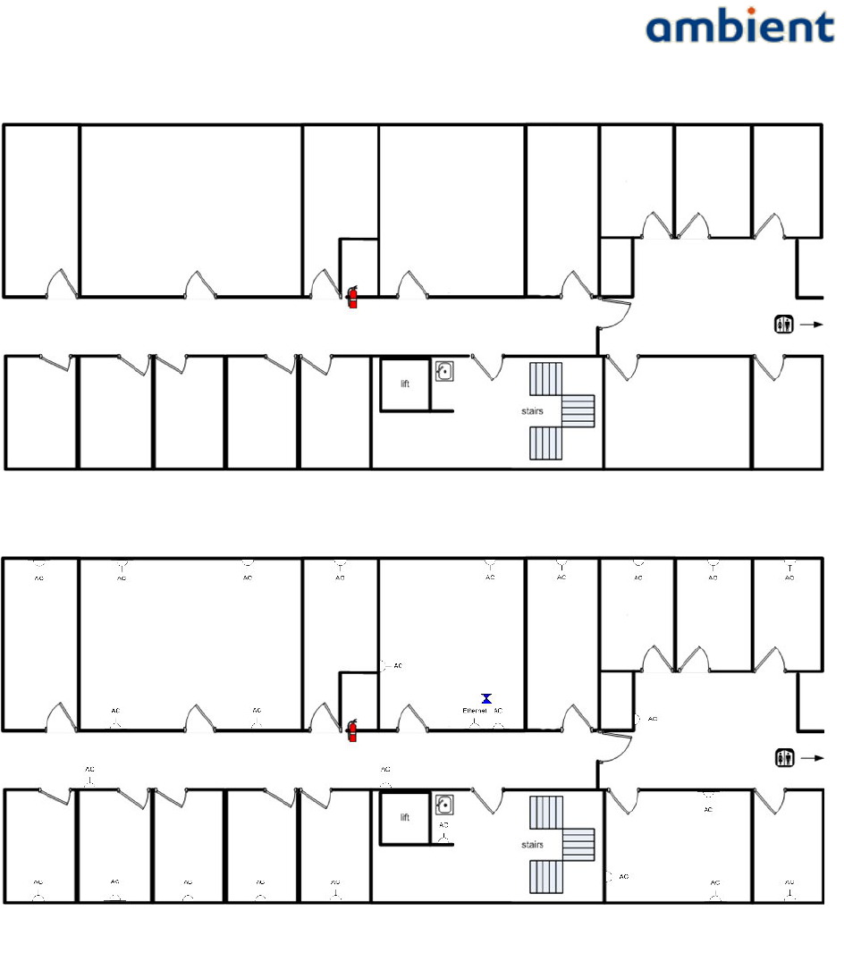
User Manual
3000 SERIES 3rd GENERATION ACTIVE RFID
55/73 Ambient Systems B.V.
Illustration 32: Deployment Map
Illustration 33: Deployment Map, AC/DC Power Outlets marked
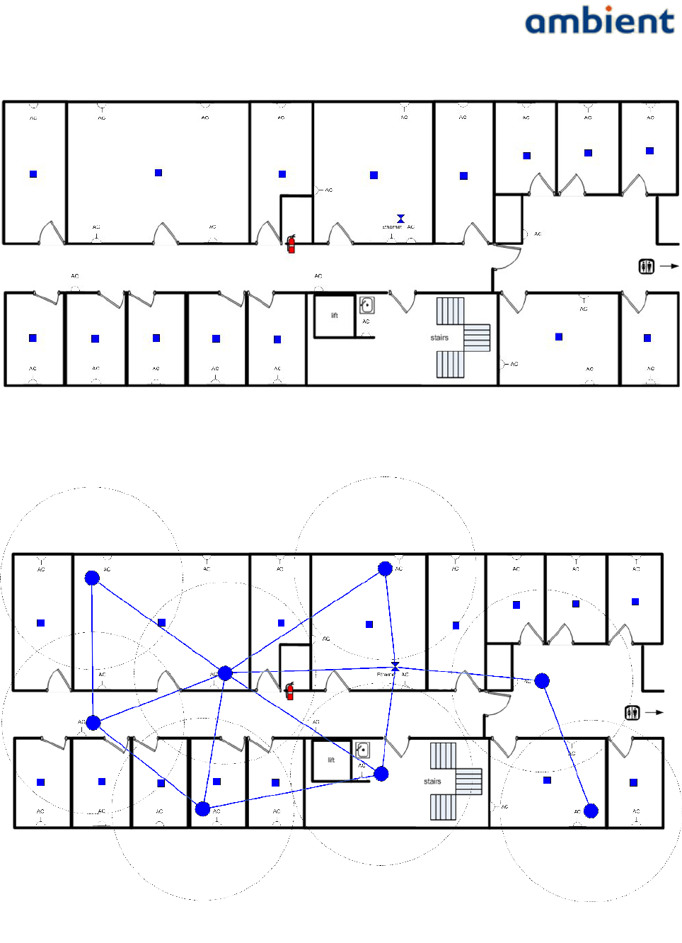
User Manual
3000 SERIES 3rd GENERATION ACTIVE RFID
56/73 Ambient Systems B.V.
Illustration 34: Deployment Map, SmartPoints marked
Illustration 35: Deployment Map, MicroRouters marked
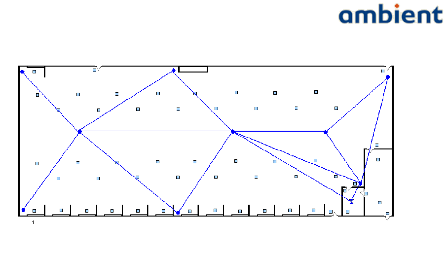
User Manual
3000 SERIES 3rd GENERATION ACTIVE RFID
57/73 Ambient Systems B.V.
Illustration 36: Example of network deployment in warehouse
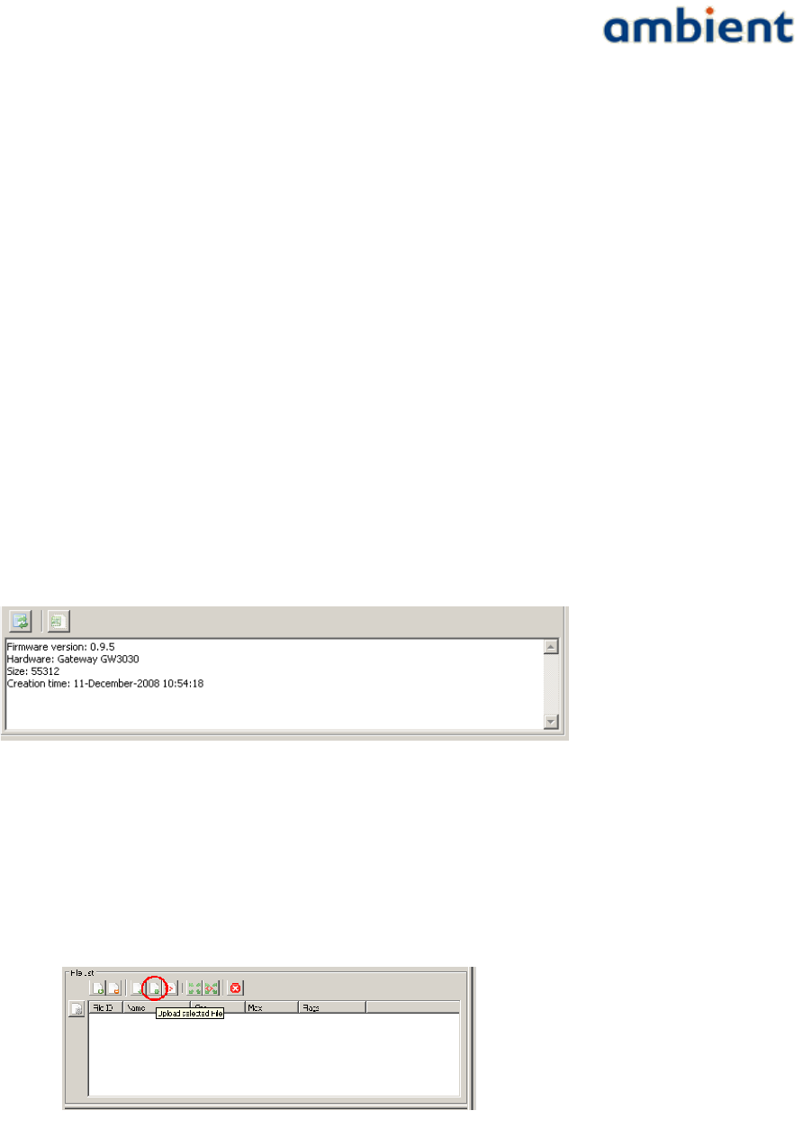
User Manual
3000 SERIES 3rd GENERATION ACTIVE RFID
9 Firmware Upgrades
This section describes the firmware upgrade procedure for all devices in an Ambient Systems
network. This upgrade has to be carried out using Ambient Studio. Basic knowledge and experience
with Ambient Studio is assumed. More information regarding Ambient Studio can be found in the
Ambient Studio user manual.
9.1 Gateway
Upgrading the firmware of the gateway has to be done by uploading the new firmware image to the
file system of the Gateway. When the complete image is uploaded, the gateway has to be reset.
Below is a step-by-step description on how to go about upgrading your Gateway firmware.
1. Obtain the latest firmware version from Ambient Systems and store it on your hard disk.
The firmware image of the gateway is always called Ambient0000.ota
2. Connect the gateway to Ambient Studio. Go to the Remote File System panel. On the left
side of the panel, select the gateway. On the right side of the screen, browse to the firmware
image and select it. On the right bottom of the screen, version information of this firmware
image is depicted (Illustration 37).
3. Press the upload file button. The file upload process should start. Confirm that you want to
upload the file to the device. Confirm if there is a warning that the file already exist and that
it will overwrite the file. The progress can be followed on the bottom of the screen. The
upload to the gateway goes relative fast (30 seconds) (Illustration 38). When the upload is
completed, the file is listed in the File List view of the Remote File System panel.
4. Go to the maintenance panel, select the gateway and press the reset button(Illustration 39).
58/73 Ambient Systems B.V.
Illustration 38: Upload file button
Illustration 37: Version information of firmware.
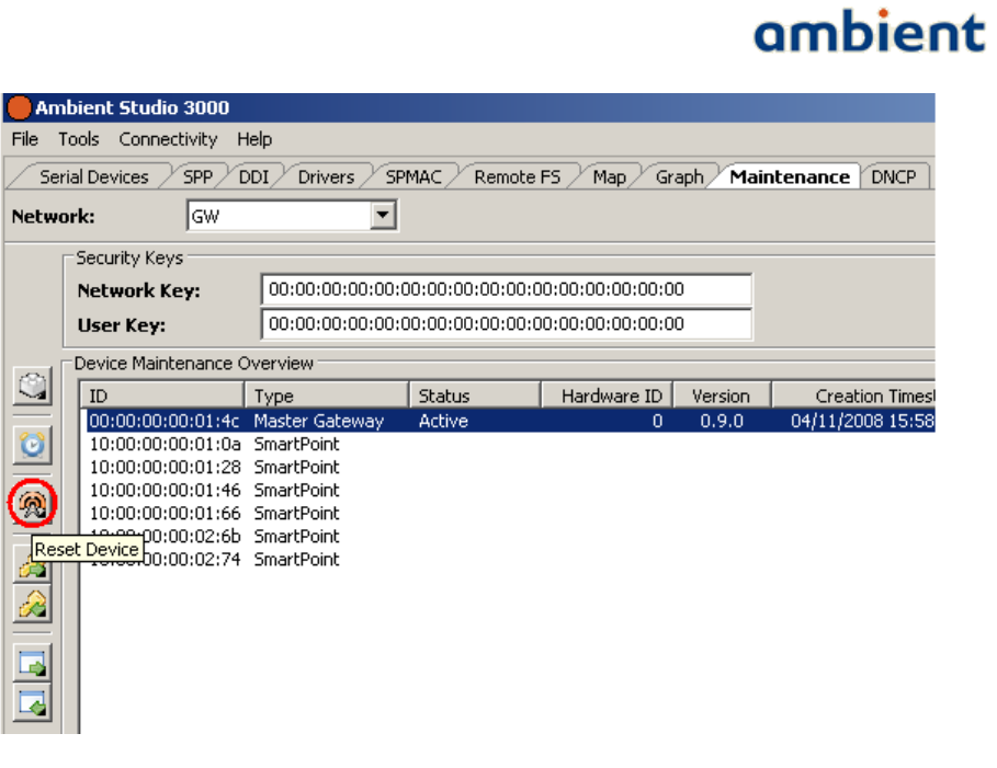
User Manual
3000 SERIES 3rd GENERATION ACTIVE RFID
5. When the gateway resets, it will boot again and the new firmware version is depicted in the
maintenance tab. Verify that it equals the version shown in step 2 of this section.
9.2 MicroRouter
In order to upload a new firmware image to the MircoRouter, two approaches can be chosen The file
upload approach as described above and the Data Dissemination approach.
9.2.1 File upload approach
In case only one MicroRouter has to be updated the File upload approach can be chosen, in any other
case the Data Dissemination approach should be chosen as it is faster.
Exactly the same steps compared to upgrading the firmware of the gateway have to be executed. The
firmware image of the MicroRouter is called Ambient0100.ota. When uploading the firmware and
resetting the device, the targeted MicroRouter has to be selected and not the GateWay. As there is
'limited' bandwidth between the Gateway and MicroRouter, the upload might take a while (15-20
minutes for a hop 1 node).
9.2.2 Data Dissemination approach
Whenever a network of a couple (of more) MicroRouters should be updated, the Data
Dissemination(DD) approach should be chosen as it is the fasted may to disseminate a file, the
firmware image, to all routers in the network. After the firmware image is disseminated, all routers
in the network have to be reset.
1. The firmware image Ambient0100.ota (of the MicroRouter) has to be uploaded to the to the
GateWay. See step 2 of 'upgrading gateway'. If the file already exist, overwrite it. If the file
59/73 Ambient Systems B.V.
Illustration 39: Reset button to reset the gateway
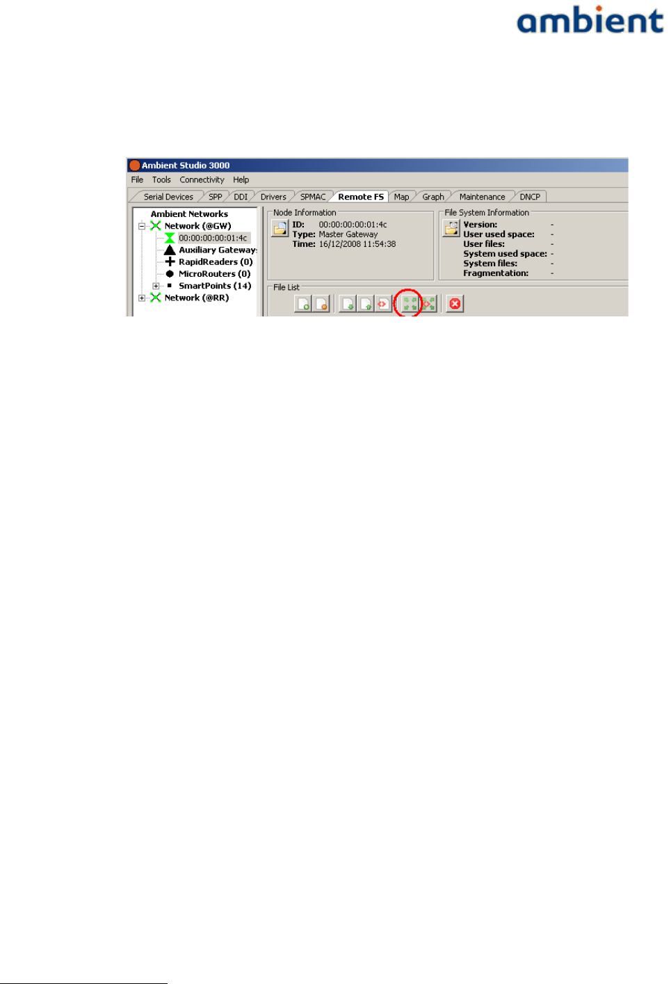
User Manual
3000 SERIES 3rd GENERATION ACTIVE RFID
system is full, delete some large files. The upload should go relative fast (30-60 seconds).
2. Select the uploaded File in the File list and press the 'Disseminate Selected File' button (see
Illustration 40).
3. Go to the Dissemination panel on the bottom of the screen(File interaction). The gateway
will disseminate the file to maximum 4 MicroRouters. When completed, these 4
MicroRouters will disseminate the firmware image to each 4 other MicroRouters. Up to the
moment that the file, the firmware image exist on the File System of all MicroRouters in the
network. For a multi-hop network with 20+ MicroRouters this might take up to a couple of
hours, depending on the topology of the network.
4. When the image has been disseminated to all routers within the network, the routers should
be reset. This can be done via the maintenance tab. When right-clicking the reset button, the
option all Infrastructure nodes should appear. When pressing this button all MicroRouters
(including gateway) will be reset.
5. As all routers transmit their version information at start up, all routers should report their
new firmware version.
9.3 SmartPoint
Upgrading the firmware of the SmartPoints has to be done using a rapid reader1 and Ambient
Studio.
The rapid reader has to be connected to Ambient Studio, the serial port has to be setup correctly and
it has to be activated, this can be done by right clicking the rapid reader and selecting a channel (the
default channel should be OK). Note that the gateway is still connected to Ambient Studio in order
to keep the network running.
Secondly, a SmartPoint has to be placed in rapid read mode, this can be done by right clicking the
SmartPoint and select 'Initiate Rapid Read Client' and select the same channel as the rapid reader. A
message is sent through the gateway towards the SmartPoint. Depending on the report period of the
SmartPoint, it will take time before the messages is received by the SmartPoint. When the message is
received it goes to rapid read mode. The rapid reader connects to the SmartPoint and one is able to
select the SmartPoint (in the tree of the Rapid Reader) and upload the firmware image
Ambient1000.ota via the file upload approach as described above. After the upload a reset is
required. Select the rapid reader network in the maintenance tab, it should list the Rapid Reader and
the SmartPoint which is in rapid reader mode.
1 Note that the rapid reader is not commercially available, only for evaluation and support purposes.
60/73 Ambient Systems B.V.
Illustration 40: Dissemination button in order to disseminate a file to all
routers

User Manual
3000 SERIES 3rd GENERATION ACTIVE RFID
When Switching to the 'gateway' network in the maintenance tab, one should see the updated
SmartPoint with the new firmware version.
If multiple SmartPoints have to be updated/upgraded a separated tool, the mass updater, can be
used as this tool runs unattended. This tool is described in the the white paper 'using the mass
updater' which can be found on the support website or by sending an email to support@ambient-
systems.net.
9.4 Remarks
●When upgrading the firmware of the gateway and the routers, it is probably easier to upload
the firmware image to the gateway but reset it after the firmware dissemination of the
MircoRouters is completed. In this case one is sure that the firmware version of all routers
and gateway is equal during the update process.
●Contact Ambient Systems Support in order to obtain a change log of the firmware version
and a list of known issues.
●If the dissemination process fails:
○Verify that the File System is not full. If the File System is full, delete some file and start
the DD process a second time, or upload the image to this MicroRouter using the File
upload approach.
○Verify that the MircoRouter has at least one, but preferable multiple good links to a
number of routers.
61/73 Ambient Systems B.V.

User Manual
3000 SERIES 3rd GENERATION ACTIVE RFID
10 Troubleshooting
This section describes solutions to the most common problems you might run into. Please, try the
solutions proposed in this section first before contacting the Ambient Support Team. Most solutions
take only a few minutes of your time and get your network up an running.
10.1 Troubleshooting the serial connection
If the serial connection fails:
1.Check if the GW3000 device is powered and correctly connected to the PC (see Section 4.4).
2.Make sure that no other PC program (such as HyperTerminal) is using the COM port
associated with your Gateway. Close all open programs and restart Ambient Studio.
3.If this is the first time that you a USB to RS232 device, you might need to reboot your PC to
enable the software drivers for the USB to RS232 device.
4.Remove all other serial and USB equipment from the PC, except the GW3000. Verify again the
COM port as described in Section 5.1.1. Make changes in Ambient Studio, if required.
5.Reopen the Serial Port in Ambient Studio by selecting
Connectivity Serial Port Open All→ → → .
6.Verify the serial connection
7.Contact the Ambient Support Team if the serial connection remains offline.
62/73 Ambient Systems B.V.

User Manual
3000 SERIES 3rd GENERATION ACTIVE RFID
11 Appendices
11.1 Appendix A: WSN Basics
Ambient Systems wireless products are based on industry standards to provide easy-to-use and
compatible Wireless Sensor Networks (WSN) within your home, business, warehouse, transport
vehicles and so forth. Strictly adhering to the IEEE 802.15.4 standard, the Ambient Systems wireless
family of products will allow you to securely access the data you want, when and where you want it.
You will be able to enjoy the freedom that Wireless Sensor Networking delivers.
11.1.1 What is Wireless?
Wireless technology is a means of communication without using wires. WSNs use a certain radio
frequency to connect wirelessly, so you have the freedom to connect WSN nodes anywhere in your
warehouse, transport unit, office, and so forth.
11.1.2 What is a Wireless Sensor Network?
A Wireless Sensor Network (WSN) is a wireless network consisting of spatially distributed
autonomous devices using sensors to cooperatively monitor physical or environmental conditions,
such as temperature, sound, vibration, pressure, motion or pollutants, at different locations. The
development of WSNs was originally motivated by military applications such as battlefield
surveillance. However, WSNs are now used in many civilian application areas, including
environment and habitat monitoring, healthcare applications, home automation, traffic control, in-
transport monitoring, cold chain, and so forth.
In addition to one or more sensors, each node in a WSN is typically equipped with a radio
transceiver or other wireless communications device, a small micro controller, and an energy source,
usually a battery. The envisaged size of a single sensor node can vary from shoebox-sized nodes
down to devices the size of grain of dust, although functioning 'nodes' of genuine microscopic
dimensions have yet to be created. The cost of sensor nodes is similarly variable, ranging from
hundreds of dollars to a few cents, depending on the size of the WSN and the complexity required
within individual sensor nodes. Size and cost constraints on sensor nodes result in corresponding
constraints on resources such as energy, memory, computational speed and bandwidth.
A WSN normally constitutes a wireless ad-hoc network, meaning that each sensor supports a multi-
hop routing algorithm, in other words: several nodes may forward data packets to the base station or
gateway.
In computer science and telecommunications, WSNs are an active research area with numerous
workshops and conferences arranged each year. Since the start of the millennium, WSN technology
has also found its way to commercial markets, clearly indicating that it has matured to a level in
which the technology is deemed fit for real-world applications.
11.1.3 Why Ambient Systems?
Ambient Systems is one of the worlds first 3rd Generation Active RFID providers that utilize this
WSN technology. It provides new possibilities that were previously hard to combine in a single
network; identification, monitoring, location determination, logging. And all this in a secure way.
Ambient Systems has developed its own network stack on top of IEEE 802.15.4. The stack has been
developed over the last years, originally as a deliverable of one of Europe's biggest research projects
into WSN (the EYES project, see www.eyes.eu.org). Ambient Systems modified the stack in such a
63/73 Ambient Systems B.V.

User Manual
3000 SERIES 3rd GENERATION ACTIVE RFID
way that it is ideally suited for large scale WSNs that have highly dynamic sensor nodes. As location
is such an important aspect, this has been incorporated into the network stack itself, enabling
SmartPoints to compute their position themselves, therefore you do not require any complex or
expensive back office software to calculate positions.
11.1.4 Who uses Wireless Sensor Networks?
WSN technology is becoming more and more popular, but primarily industrial users have adopted
it. Nevertheless, whether it is for home, office, warehouse, transport vehicles, Ambient Systems has a
solution for it.
Generally
●No need for cables
●Simple and easy to use
●Can operate for years on batteries, automatically indicates battery depletion by means of
alerts
●All-in-1
Small Office
●Temperature Monitoring
●Humidity Monitoring
●Localization of valuable Assets, such as laptops, beamers, and so forth
Warehouses
●Temperature Monitoring, for example in climate controlled storage
●Humidity Monitoring
●Door Monitoring
●Localization of valuable assets, such as forklifts, containers, and so forth.
In-Transit
●Used for Returnable Transport Items (RTIs) such as rolling containers, pallets, and so forth,
in order to check their temperature, track their location, and trace their history using 1 MB of
data storage
●Provided detailed information about what RTIs are in your transport vehicle
11.1.5 Where are Wireless Sensor Networks used?
WSN technology is expanding everywhere. The power of self-organizing, self-healing, ad-hoc, mesh
networks can be applied in almost every application scenarios.
Ambient Systems Channel Partners have applied the technology in many diverse applications.
●... in cold chain scenarios, monitoring the temperature and logging weeks of data which is
flushed upon return,
●in the Great Barrier Reef, monitoring the status of buoys which communicate using the WSN
back bone infrastructure, before transmitting the data to the shore,
64/73 Ambient Systems B.V.

User Manual
3000 SERIES 3rd GENERATION ACTIVE RFID
●in large warehouses, where they monitor the temperature inside of large piles of bulk
material such as cocoa,
●in trucks and trailers, monitoring the real-time temperature and presence of RTIs in the back
of the truck,
●in remote nature reserves, monitoring the status of rattraps enormously increasing the
efficiency of park rangers,
●in greenhouses, monitoring the ground moisture levels,
●on golf courses to monitor ground moisture levels of the green, and so forth.
It is safe to say that WSN technology can be applied in almost any application area.
65/73 Ambient Systems B.V.

User Manual
3000 SERIES 3rd GENERATION ACTIVE RFID
11.2 Appendix B: Networking Basics
This chapter is intended as an introduction to wireless mesh networking in general and to an
Ambient network in specific. For a detailed overview please look at the White Paper “Ambient 3000-
Series Network”.
11.2.1 Wireless Sensor Networks
An Ambient network is classified as a so-called Wireless Sensor Network (WSN). WSNs typically
consist of small devices, called sensor nodes. These nodes have an on-board microprocessor that
allows interfacing with other devices such as temperature sensors. An additional key feature of such
a node is the radio transceiver. Typically a sensor node is battery powered requiring energy efficient
behaviour to guarantee a long lifetime. The most power consuming part of a node is its radio, so the
more a node uses its radio, the more energy it consumes. As a rule of thumb, non-meshing nodes
have a lifetime in the range of years, whereas meshing node batteries have a lifetime in the range of
months.
The concept of a WSN is known in the Computer Science field called 'Ubiquitous Computing' which
is also known as 'Pervasive Computing'. WSNs are regarded as the next evolution in
telecommunication and Computer Science, enabling an entirely new field of research and
commercial possibilities. Most important aspect is that it offers the possibility for back office systems
to obtain information about the physical world.
For more information about WSNs, visit our website at www.ambient-systems.net.
11.2.2 Characteristics
There are many different types of WSNs that are grouped by various characteristics. This section
describes a subset of these characteristics that are implemented in Ambient networks.
The strength of an Ambient network is that it provides a wireless mesh networking solution which is
easy to install and self organizing. Making use of this functionality, specific application behaviour
can be implemented without requiring detailed technical background information about wireless
mesh networks.
The following table sums up some of the key characteristics of an Ambient network.
C h a r a c t e r i s t i c D e s c r i p t i o n
Multi-hop An Ambient Network is multi-hop, enabling two nodes that are not in
each others radio range to communicate with each other by relaying data
through intermediate nodes. As a result, large areas can be covered by a
single network.
Ad-hoc The network is ad-hoc, meaning that the whole network set-up is
automated. Nodes have the ability to discover and join the network
automatically, without the need of manual configuration. Also, the
network dynamically adapts to changes such as moving nodes or varying
radio ranges due to environmental interference.
Self-Healing The network is self-healing, which means that when a relaying node fails
alternative paths are used to deliver data at the destination. The entire
routing of messages throughout the network is adjusted automatically.
66/73 Ambient Systems B.V.
User Manual
3000 SERIES 3rd GENERATION ACTIVE RFID
Energy-Efficient The network is energy-efficient. Nodes maximize their sleep time - and
therefore increase battery lifetime - by communicating only at certain
tightly synchronized time intervals. An important reason for this energy-
efficiency stems from the underlying network principles applied in
Ambient networks. It is a combination of Time Division Multiple Access
(TDMA) and Carrier Sense Multiple Access (CSMA) which enable the
nodes to use their radios in the most energy-efficient manner.
Robust As the network is multi-hop, it enables you to create redundancy in your
networks by providing several paths between different nodes. Whenever a
single MR fails, there are still other routes available towards the GW. This
approach provides a high degree of robustness to the system.
Secure Various security mechanisms are in place that protect sensitive
information flowing through your networks. One of these mechanisms, for
example, is the use of a network key; by setting such a key all
communication is encrypted and only interpretable by trusted parties that
have the appropriate security keys.
Localization An Ambient network has integrated peripherals and network interactions
that provide the means for a node to locate itself. As SPs do not need to
register with the network, they can observe beacon messages that are
being sent and derive a position estimate from the information gathered.
11.2.3 Network Size
Network size is an important aspect when planning a deployment for a certain application and
considering the desired behaviour of the SmartPoints. Effectively, the size of the network is related
to the two distinctive layers that exist in a network; on one hand there is the infrastructure which
makes up the communication backbone and provides the appropriate coverage, on the other hand
there are the SmartPoints whose number is only limited by the number of beacon messages they
consume.
The size of the infrastructure is fixed and determined by the type of GW used.
The number of SPs is dependent on the reporting frequency of the SPs and the number of MRs. Each
GW and MR transmit certain beacon messages. These beacon messages are used by SPs to
communicate with the infrastructure and locate themselves. By default, a GW and MR transmit 2 of
such beacons per second. They can be configured to transmit 4 of those, if deemed necessary, but the
SP load needs to be taken into account.
Consider this example; there are 15 MRs in a network that is build up using a GW3000. The SP300T
reports every 5 minutes by default. Then the absolute maximum number of SmartPoints is 5 x 60 x 2
x (15+1) = 9600. However; messages from SPs can collide and message loss will occur. Also, if all SPs
are in range of just a few MRs, there will be a network unbalance and even more collisions will
occur. The network architecture has various means to handle these unbalanced loads by various
mechanisms and congestion control, ensuring maximum achievable performance in the worst of
scenarios.
Adding more MRs to the nework will, in most cases' solve the aforementioned problem. Contact
support@ambient-systems.net for more information on this topic.
67/73 Ambient Systems B.V.

User Manual
3000 SERIES 3rd GENERATION ACTIVE RFID
A rule of thumb should be that each SmartPoint should be in reach of at least 3 MRs at any given
time.
68/73 Ambient Systems B.V.

User Manual
3000 SERIES 3rd GENERATION ACTIVE RFID
11.3 Appendix C: Technical Specifications
Please refer to the individual data sheets of the various products to obtain detailed technical
specifications.
69/73 Ambient Systems B.V.
User Manual
3000 SERIES 3rd GENERATION ACTIVE RFID
11.4 Appendix D: Technical Support
All customers can contact Ambient Systems technical support through our web site or by email.
Before you contact technical support, please have the following ready:
●Model number of the product (e.g. MR3000, SP3000, etc.)
●Hardware Revision (located on the label of the device)
●Current firmware version (can be obtained using Ambient Studio)
●Serial ID (located on the label of the device)
Also, if you have encountered any problems visit the support section of our website where you can
find software updates and user documentation as well as Frequently Asked Questions (FAQ) and
answers to technical issues.
Website www.ambient-systems.net
Then browse to the support section
E - m a i l support@ambient-systems.net
70/73 Ambient Systems B.V.

User Manual
3000 SERIES 3rd GENERATION ACTIVE RFID
11.5 Appendix E: Warranty & Disclaimer
To all products and related documentation Ambient Systems B.V. Terms & Conditions (T&C) apply.
The T&C can be found and downloaded from our website.
11.5.1 Trademarks
Ambient is a registered trademark of Ambient Systems B.V. Other trademarks or registered
trademarks are the property of their respective owners.
11.5.2 Copyright Statement
No part of this publication or documentation accompanying this product may be reproduced in any
form or by any means or used to make any derivative such as translation, transformation, or
adaptation without permission from Ambient Systems B.V.
Contents are subject to change without prior notice.
Copyright ©2009 by Ambient Systems B.V. All rights reserved.
11.5.3 CE Mark Warning
In a domestic environment, this product may cause radio interference, in which case the user may be
required to take adequate measures.
11.5.4 Manufacturer Declaration of Conformity
Hereby, Ambient Systems BV declares that the 3000 Series products are in compliance with the
essential requirements and other relevant provisions of Directive 1999/5/ EC. A copy of the
Declaration of Conformity can be obtained by sending a mail to support@ambient-systems.net
71/73 Ambient Systems B.V.
User Manual
3000 SERIES 3rd GENERATION ACTIVE RFID
11.6 Appendix F: Recycling
a) General Information
Electric and electronic devices must not be disposed of in the domestic waste. Please dispose of the
inoperative product in accordance with the current legal
regulations.
b) Batteries and Rechargeable Batteries
You, as the end user, are required by law (Battery Ordinance) to return all used
batteries/rechargeable batteries. Disposal of them in the household waste is prohibited!
Contaminated batteries/rechargeable batteries are labelled with these symbols to indicate that
disposal in domestic waste is forbidden. The description of dangerous heavy metal constituents are:
Cd=cadmium, Hg=mercury, Pb=lead (name on battery/rechargeable battery, e.g. under the trash
icons on the left). You can return your exhausted batteries/rechargeable batteries free of charge to
any authorized disposal station in your local authority, to our stores or to any other store where
batteries/rechargeable batteries are sold. You thus fulfil your statutory obligations and contribute to
the protection of the environment.
For more information contact support@ambient-systems.net
11.7 Appendix G: Registration
Please sent an email to support@ambient-systems.net to register the Ambient 3000 Series products.
72/73 Ambient Systems B.V.
User Manual
3000 SERIES 3rd GENERATION ACTIVE RFID
11.8 Appendix H: Manual Revisions
Ambient Systems B.V. reserves the right to revise this publication and to make changes in the
content hereof without obligation to notify any person or organization of such revisions or changes.
R e v i s i o n D a t e D e s c r i p t i o n
1.0 02/04/09 Release 1.0 documentation.
73/73 Ambient Systems B.V.