Amcrest Technologies AMC015 2K/3MP Dual-band Fixed Wireless IP Camera User Manual
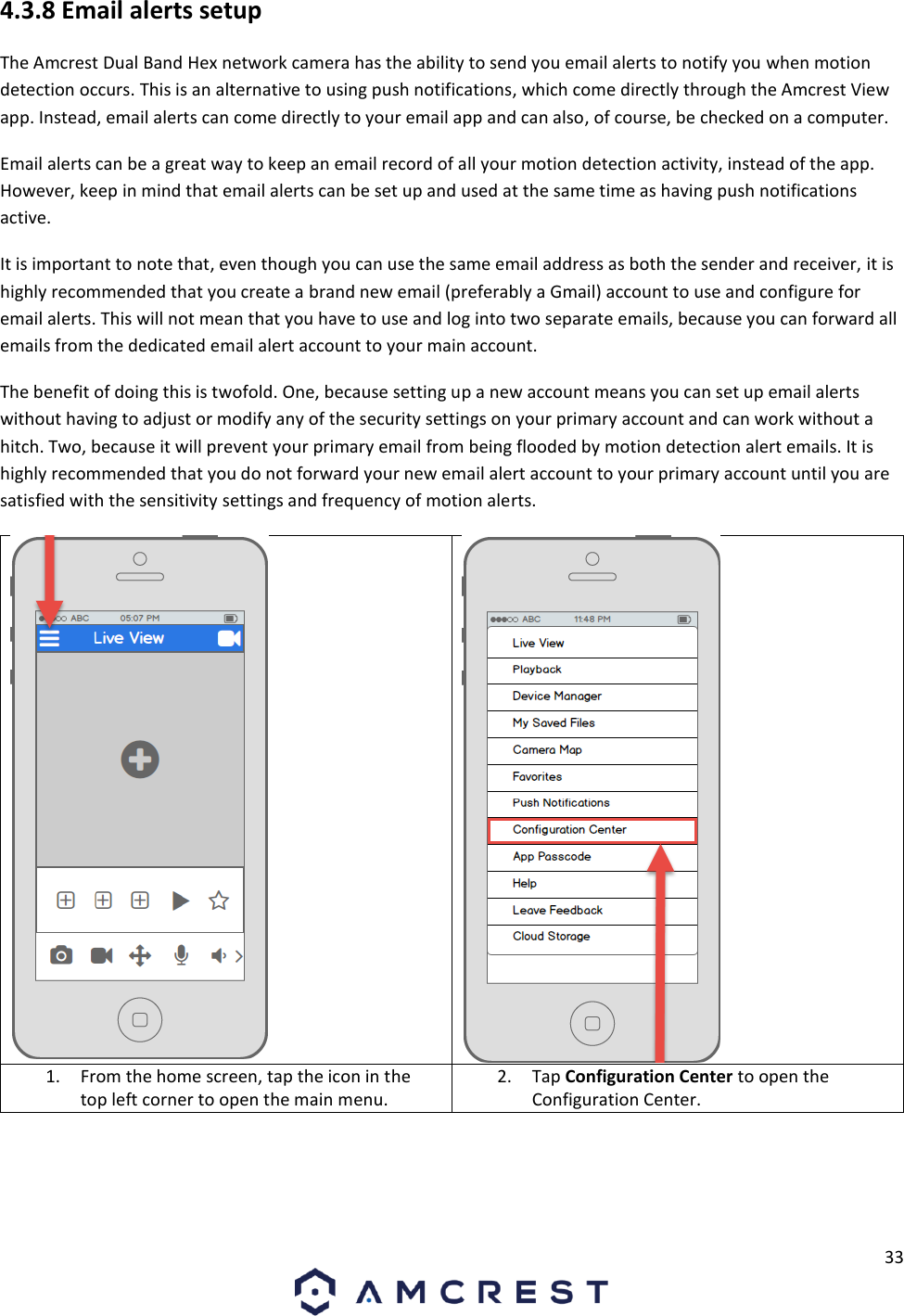
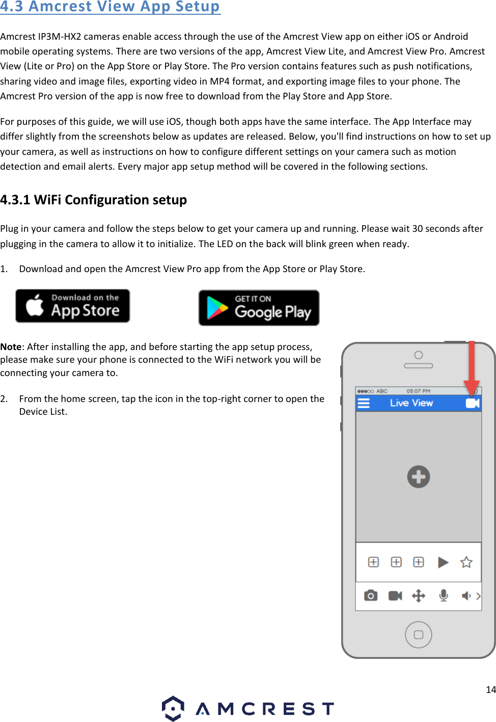
Amcrest Technologies LLC 2K/3MP Dual-band Fixed Wireless IP Camera Users Manual
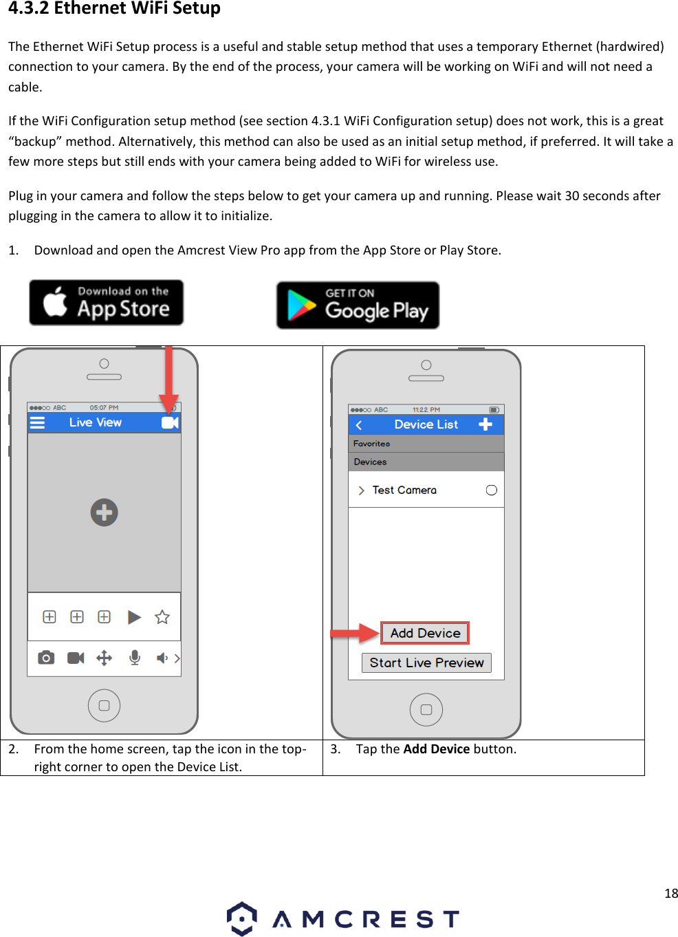
UserManual.wiki
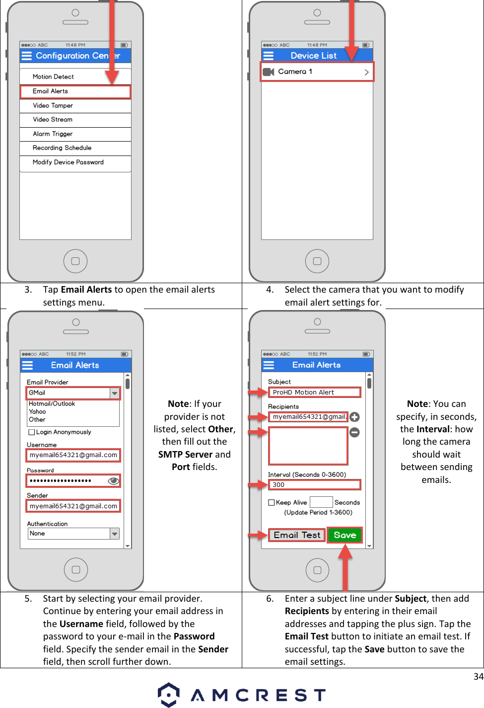
>
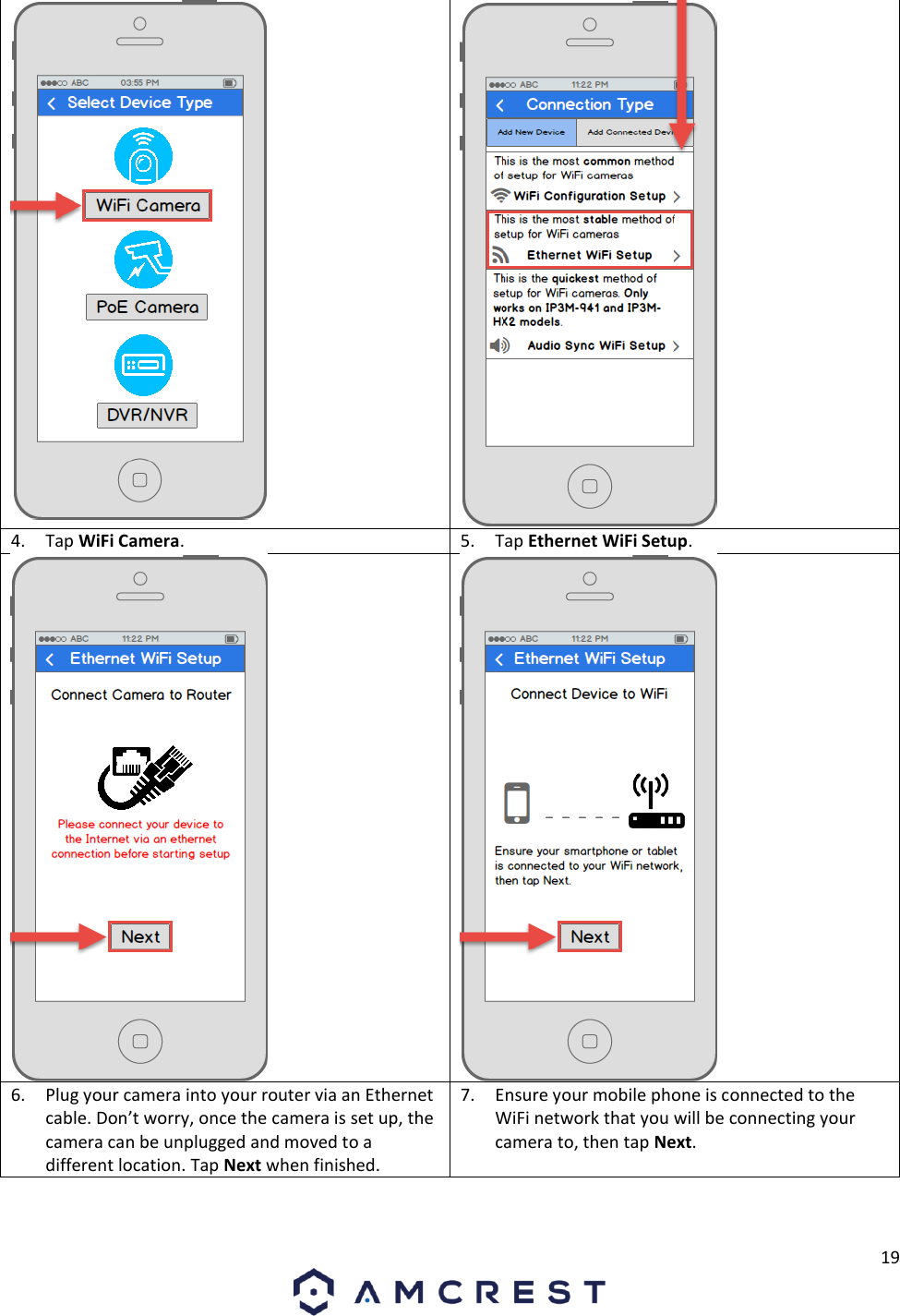
Amcrest Technologies
>
AMC015 User Manual
Users Manual
Navigation menu
Upload a User Manual
Namespaces
Wiki Guide
HTML
PDF
Info
Views
User Manual
Discussion / Help
Navigation

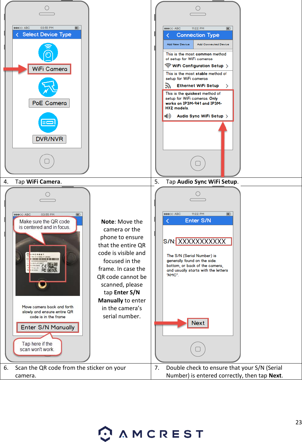
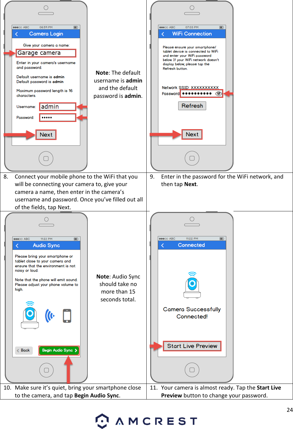
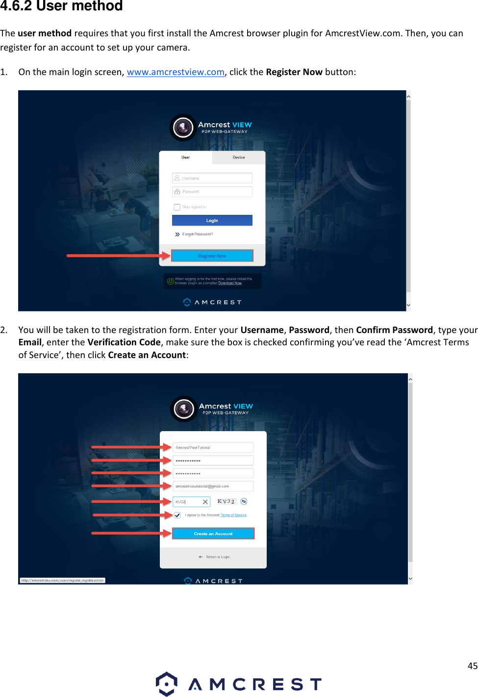
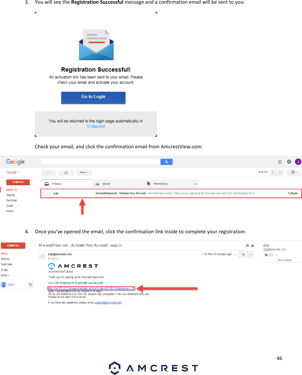
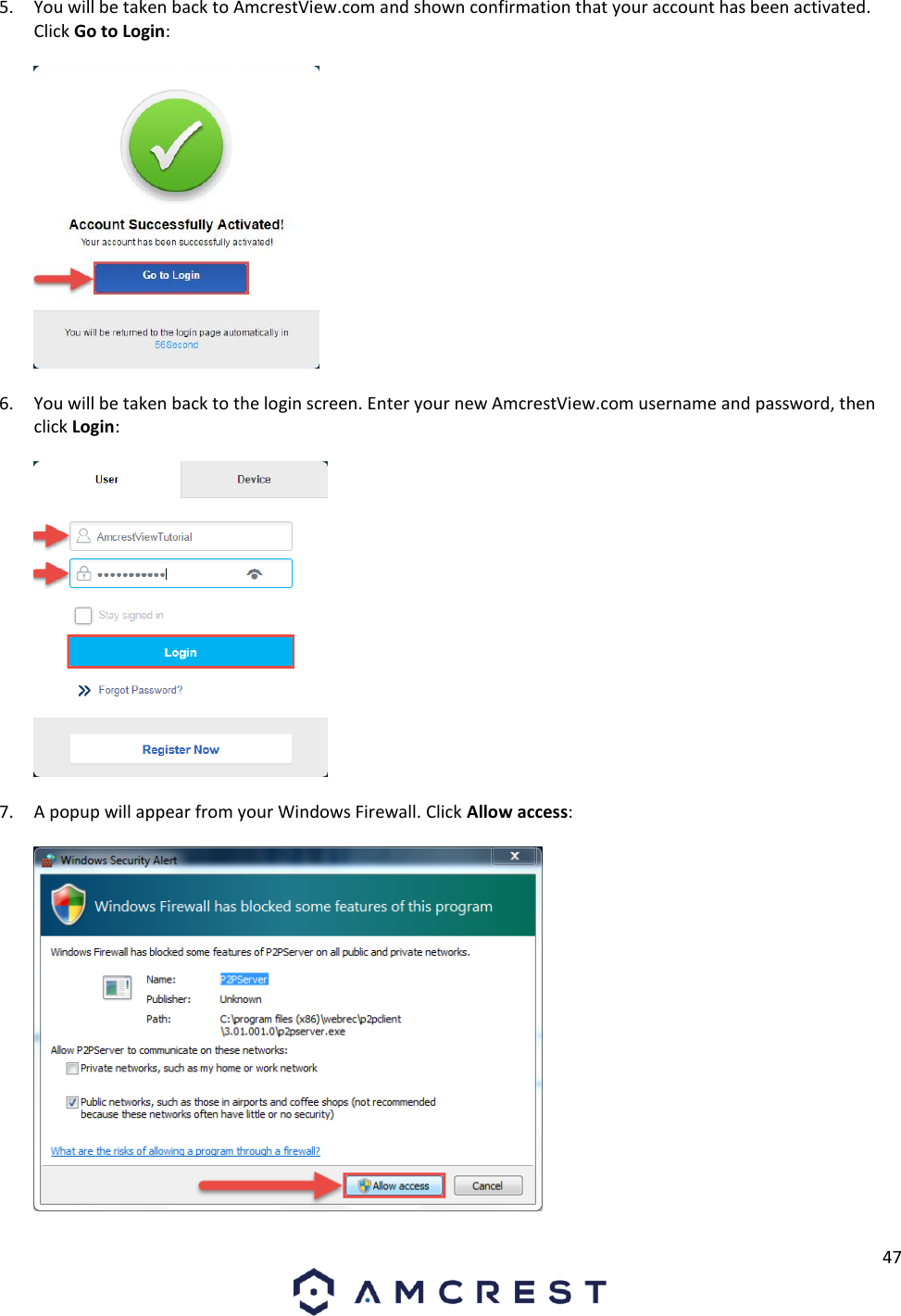
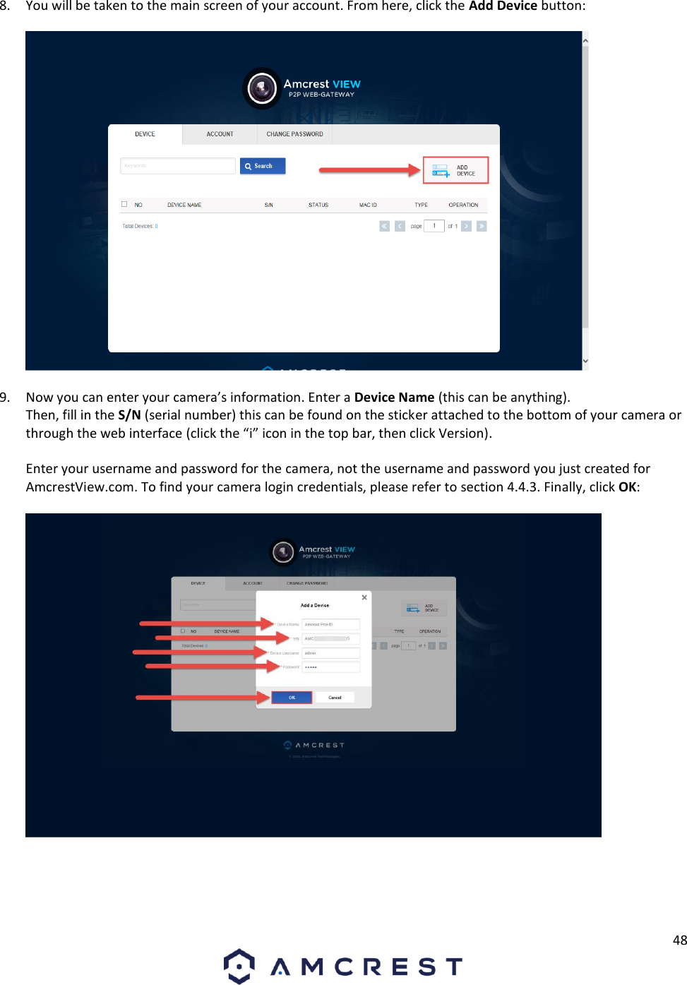
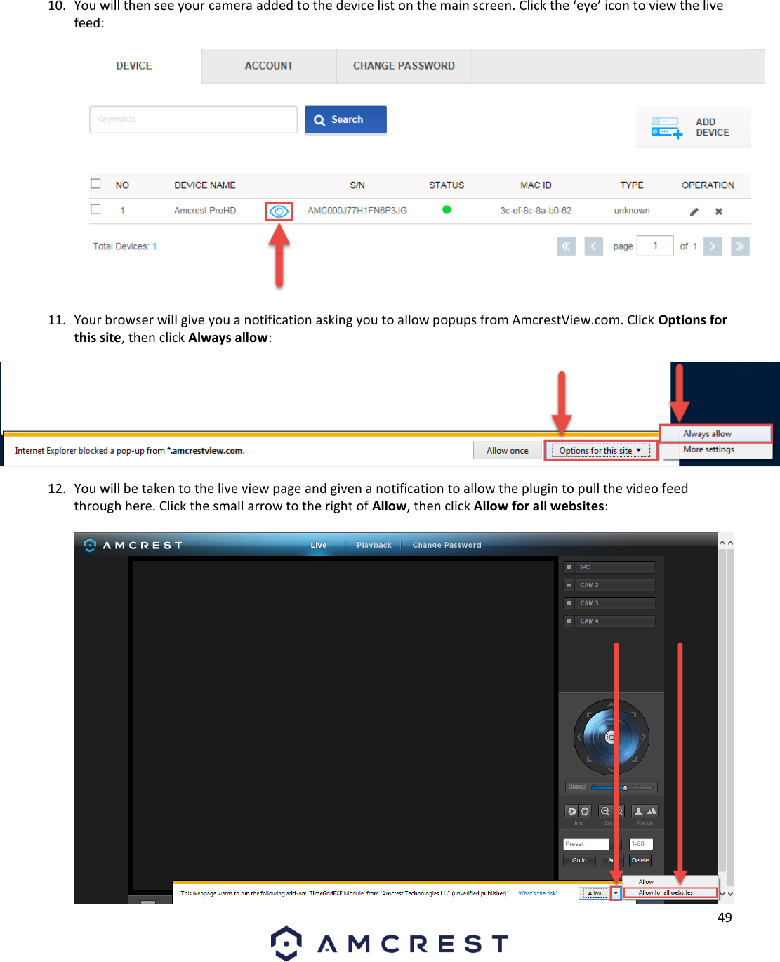
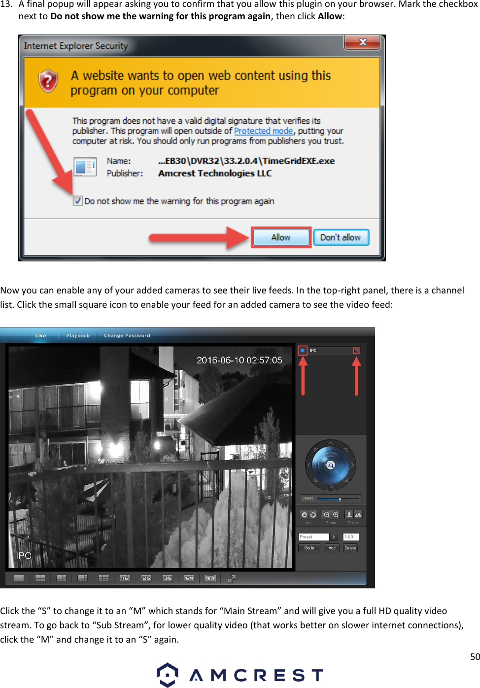
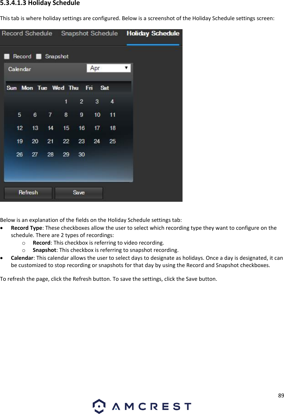
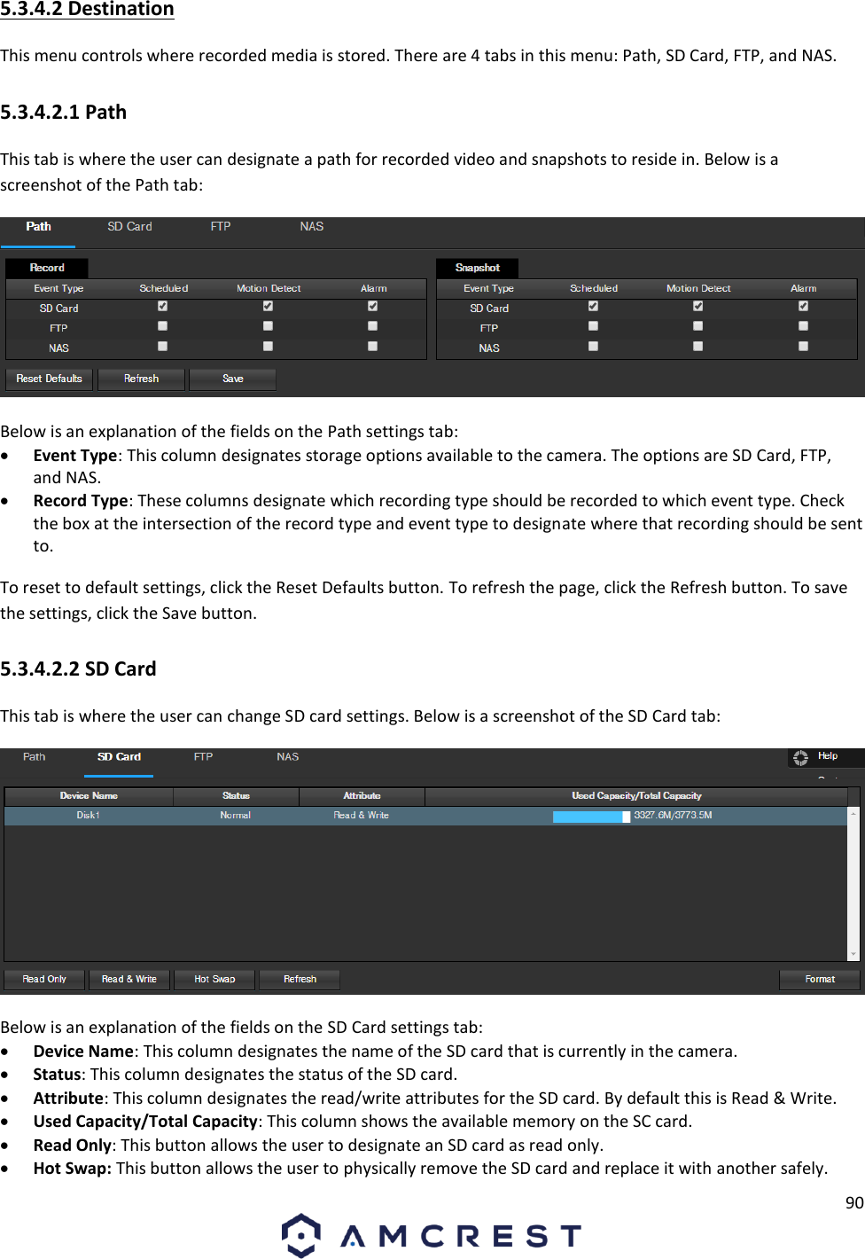
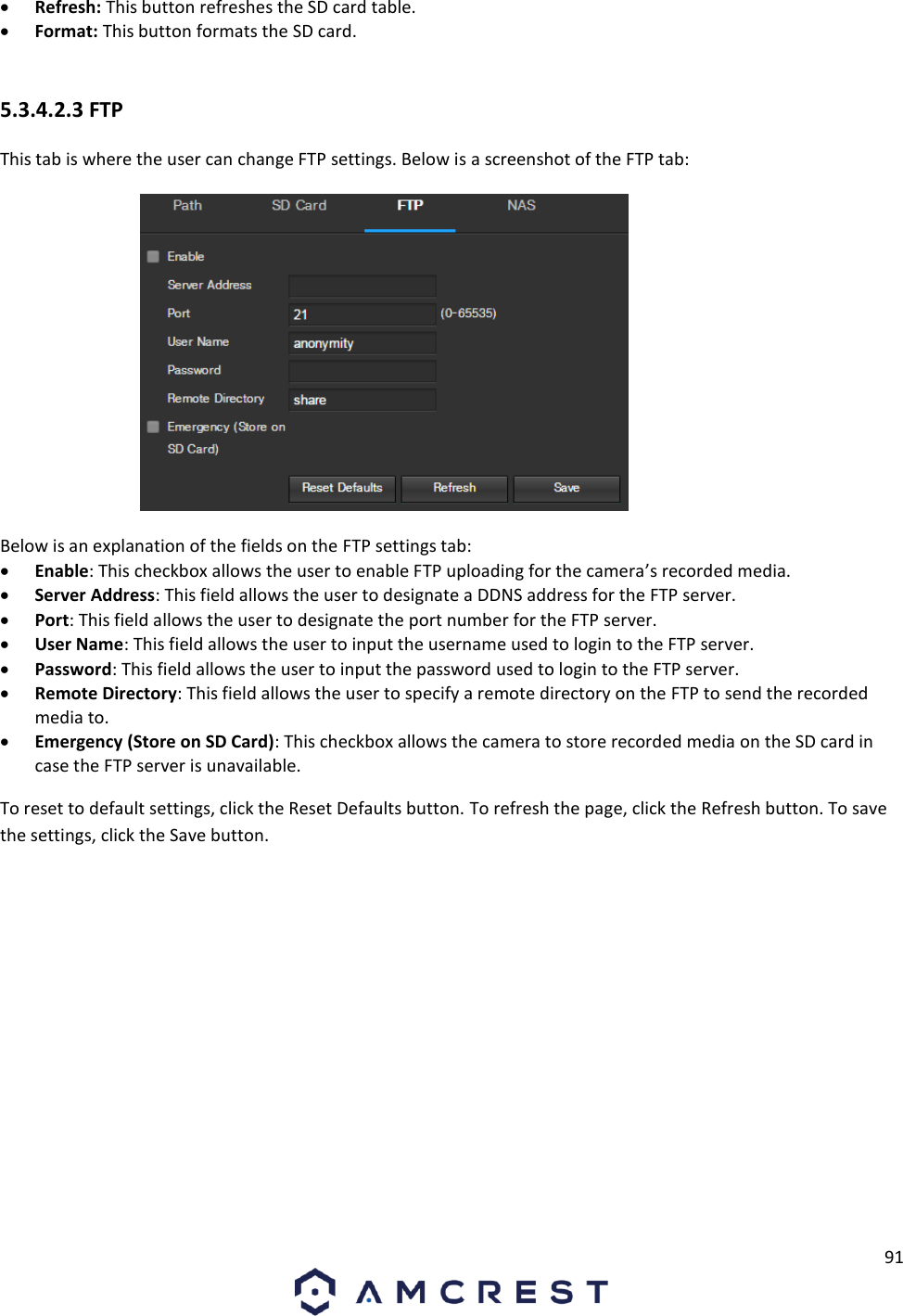
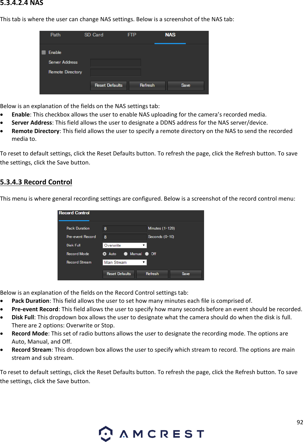
![20 Note: Move the camera or the phone to ensure that the entire QR code is visible and focused in the frame. In case the QR code cannot be scanned, please tap Enter S/N Manually to enter in the camera’s serial number. 8. Scan the QR code [QR code icon] from the sticker on your camera. 9. Double check to ensure that your S/N (Serial Number) is entered correctly. Then, tap Next. Note: The default username is admin and the default password is admin. 10. Give your camera a name, then enter in the camera’s username and password. Once you’ve filled out all of the fields, tap Next. 11. Pick a WiFi network, enter in the password, and tap Next.](https://usermanual.wiki/Amcrest-Technologies/AMC015/User-Guide-3648570-Page-20.png)