American Power Conversion Bypass Static Users Manual MW UM 990 1756
Bypass Static to the manual 5cfad3c6-b581-4e03-8e9b-3aa204d7e78f
2015-02-05
: American-Power-Conversion American-Power-Conversion-Bypass-Static-Users-Manual-508419 american-power-conversion-bypass-static-users-manual-508419 american-power-conversion pdf
Open the PDF directly: View PDF ![]() .
.
Page Count: 56
- Safety
- UPS Display
- Display Symbols and Buttons
- UPS Summary Screen
- Input Summary Screens
- Output Summary Screens
- Bypass Summary Screens
- Battery Summary Screens
- Operation Screen
- UPS Start-Up Screen
- UPS Shutdown screen
- Online to Static Bypass Screen
- Static Bypass to Online Screen
- Network Configuration Screens
- User Configuration Screens
- Event Log Screen
- Predictive Maintenance Screens
- Operation Modes
- Alarms/Troubleshooting
- APC Symmetra MW Remote Display
- Warranty
- Appendix A
- 990-1756A-ENfc.pdf
- Safety
- UPS Display
- Display Symbols and Buttons
- UPS Summary Screen
- Input Summary Screens
- Output Summary Screens
- Bypass Summary Screens
- Battery Summary Screens
- Operation Screen
- UPS Start-Up Screen
- UPS Shutdown screen
- Online to Static Bypass Screen
- Static Bypass to Online Screen
- Network Configuration Screens
- User Configuration Screens
- Event Log Screen
- Predictive Maintenance Screens
- Operation Modes
- Alarms/Troubleshooting
- APC Symmetra MW Remote Display
- Warranty
- Appendix A
- 990-1756A-ENbc.pdf
- Safety
- UPS Display
- Display Symbols and Buttons
- UPS Summary Screen
- Input Summary Screens
- Output Summary Screens
- Bypass Summary Screens
- Battery Summary Screens
- Operation Screen
- UPS Start-Up Screen
- UPS Shutdown screen
- Online to Static Bypass Screen
- Static Bypass to Online Screen
- Network Configuration Screens
- User Configuration Screens
- Event Log Screen
- Predictive Maintenance Screens
- Operation Modes
- Alarms/Troubleshooting
- APC Symmetra MW Remote Display
- Warranty
- Appendix A

Symmetra MW UPS
w/ Internal
Bypass Static Switch
User
Guide

Contents
Symmetra® MW with Internal Bypass Static Switch - User Guide - 990-1756A-001 i
Safety ......................................................................1
IMPORTANT SAFETY INSTRUCTIONS
- SAVE THESE INSTRUCTIONS . . . . . . . . . . . . . . . . . . . . . . . . . . 1
Symbols used in this guide . . . . . . . . . . . . . . . . . . . . . . . . . 1
User Safety . . . . . . . . . . . . . . . . . . . . . . . . . . . . . . . . . . . . 2
UPS Display..............................................................3
Display Symbols and Buttons. . . . . . . . . . . . . . . . . . . . . . . . . . . 3
Navigation symbols . . . . . . . . . . . . . . . . . . . . . . . . . . . . . . 3
Screen symbols . . . . . . . . . . . . . . . . . . . . . . . . . . . . . . . . . 3
Buttons . . . . . . . . . . . . . . . . . . . . . . . . . . . . . . . . . . . . . . 4
UPS Summary Screen. . . . . . . . . . . . . . . . . . . . . . . . . . . . . . . . . 5
Input Summary Screens . . . . . . . . . . . . . . . . . . . . . . . . . . . . . . . 6
Output Summary Screens . . . . . . . . . . . . . . . . . . . . . . . . . . . . . 7
Bypass Summary Screens . . . . . . . . . . . . . . . . . . . . . . . . . . . . . . 8
Battery Summary Screens . . . . . . . . . . . . . . . . . . . . . . . . . . . . . 9
Operation Screen . . . . . . . . . . . . . . . . . . . . . . . . . . . . . . . . . . 10
UPS Start-Up Screen. . . . . . . . . . . . . . . . . . . . . . . . . . . . . . . . . 11
UPS Shutdown screen . . . . . . . . . . . . . . . . . . . . . . . . . . . . . . . 12
Online to Static Bypass Screen. . . . . . . . . . . . . . . . . . . . . . . . . 13
Static Bypass to Online Screen. . . . . . . . . . . . . . . . . . . . . . . . . 14
Network Configuration Screens . . . . . . . . . . . . . . . . . . . . . . . . 15
Network Settings screen . . . . . . . . . . . . . . . . . . . . . . . . . . 15
E-mail Settings screen . . . . . . . . . . . . . . . . . . . . . . . . . . . 16
SNMP Settings screen . . . . . . . . . . . . . . . . . . . . . . . . . . . . 17
Remote Monitoring Service Settings screen . . . . . . . . . . . . . 18
APC ISX Manager Settings screen . . . . . . . . . . . . . . . . . . . . 19
ii Symmetra® MW with Internal Bypass Static Switch - User Guide - 990-1756A-001
User Configuration Screens . . . . . . . . . . . . . . . . . . . . . . . . . . . 20
Touch-Screen Settings screen . . . . . . . . . . . . . . . . . . . . . . 20
Password Settings screen . . . . . . . . . . . . . . . . . . . . . . . . . 21
Modbus Settings screen . . . . . . . . . . . . . . . . . . . . . . . . . . 21
Regional Settings screen . . . . . . . . . . . . . . . . . . . . . . . . . 22
Battery Test screen . . . . . . . . . . . . . . . . . . . . . . . . . . . . . 22
Event Log Screen . . . . . . . . . . . . . . . . . . . . . . . . . . . . . . . . . . . 24
Predictive Maintenance Screens . . . . . . . . . . . . . . . . . . . . . . . . 25
Inverter DC Capacitors screen . . . . . . . . . . . . . . . . . . . . . . 25
Inverter AC Capacitors screen . . . . . . . . . . . . . . . . . . . . . . 26
Top Fans screen . . . . . . . . . . . . . . . . . . . . . . . . . . . . . . . 27
Inverter Fans screen . . . . . . . . . . . . . . . . . . . . . . . . . . . . 28
Main Static Switch Fans screen . . . . . . . . . . . . . . . . . . . . . 29
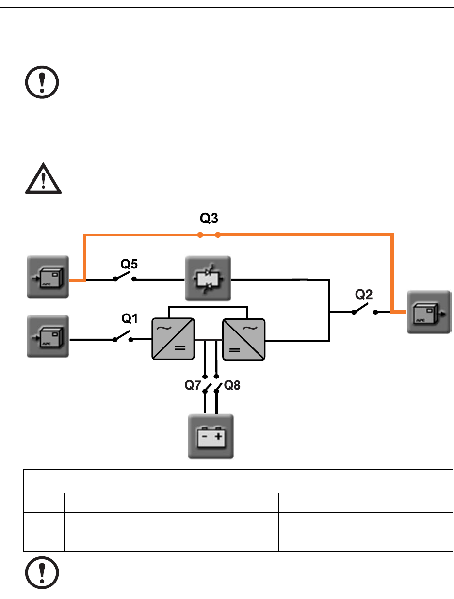
Operation Modes................................................... 31
On-line Operation . . . . . . . . . . . . . . . . . . . . . . . . . . . . . . . . . . 31
Battery Operation . . . . . . . . . . . . . . . . . . . . . . . . . . . . . . . . . . 32
Bypass Operation . . . . . . . . . . . . . . . . . . . . . . . . . . . . . . . . . . 33
Manual Bypass Operation . . . . . . . . . . . . . . . . . . . . . . . . . . . . 34
System Start-Up from Manual Bypass Operation . . . . . . . . . . . . 35
System Start-Up from Manual Bypass to Online Operation of
single mains/utility system - Step-by-Step . . . . . . . . . . . . . . 36
System Start-Up from Manual Bypass to Online Operation of
dual mains/utility system - Step-by-Step . . . . . . . . . . . . . . . . 36
System Shutdown from Online to Manual Bypass Operation . . 37
System Shutdown from Online to Manual Bypass Operation of
single mains/utility systems - Step-by-Step . . . . . . . . . . . . . . 38
System Shutdown from Online to Manual Bypass Operation of
dual mains/utility systems - Step-by-Step . . . . . . . . . . . . . . . 38
Transfer from Online to Static Bypass Operation . . . . . . . . . . . 39
Transfer from Static Bypass to Online Operation . . . . . . . . . . . 40
Symmetra® MW with Internal Bypass Static Switch - User Guide - 990-1756A-001 iii
Alarms/Troubleshooting .........................................41
Alarm Types . . . . . . . . . . . . . . . . . . . . . . . . . . . . . . . . . . . . . . 41
Info . . . . . . . . . . . . . . . . . . . . . . . . . . . . . . . . . . . . . . . . 41
Warning . . . . . . . . . . . . . . . . . . . . . . . . . . . . . . . . . . . . 41
Severe . . . . . . . . . . . . . . . . . . . . . . . . . . . . . . . . . . . . . . 41
View active alarms . . . . . . . . . . . . . . . . . . . . . . . . . . . . . . 42
APC Symmetra MW Remote Display........................43
Starting web-based remote session . . . . . . . . . . . . . . . . . . . 44
Warranty ...............................................................45
Factory Warranty . . . . . . . . . . . . . . . . . . . . . . . . . . . . . . . . . . 45
Life Support Policy. . . . . . . . . . . . . . . . . . . . . . . . . . . . . . . . . . 46
Appendix A............................................................47
Air Filter Exchange . . . . . . . . . . . . . . . . . . . . . . . . . . . . . . . . . 47
Symmetra® MW with Internal Bypass Static Switch - User Guide - 990-1756A-001 1
Safety
IMPORTANT SAFETY INSTRUCTIONS
- SAVE THESE INSTRUCTIONS
This guide contains important instructions that should be followed when handling the UPS, Battery
Enclosures, and Batteries.
Symbols used in this guide
WARNING!
Indicates an electrical hazard, which, if not avoided, could result in injury or death.
CAUTION!
Indicates a hazard, which, if not avoided, could result in injury or death.
Note
Indicates important information.
Indicates that more information is available on this subject in a different section of this
manual.
See also
Indicates that more information is available on the same subject in a different manual.

Safety: IMPORTANT SAFETY INSTRUCTIONS - SAVE THESE INSTRUCTIONS
2 Symmetra® MW with Internal Bypass Static Switch - User Guide - 990-1756A-001
User Safety
WARNING!
User functions: For safety reasons the user may only
- Remove the finishing panels for air filter exchange
- Operate the UPS display.
WARNING!
The UPS can be powered from more than one source.
CAUTION!
The system is equipped with an optional auto-start function, enabling the system to start
without any warning when power is applied.
Note
Typically, the UPS installation will be connected to an EPO (Emergency Power Off)
button located on a wall near the entrance to the room. If activated, the EPO switches off
power to the UPS, disconnects the UPS output, and switches off power to the entire
room. This action will disconnect support to the load if the UPS is online.
Symmetra® MW with Internal Bypass Static Switch - User Guide - 990-1756A-001 3
UPS Display
Display Symbols and Buttons
Navigation symbols
Screen symbols
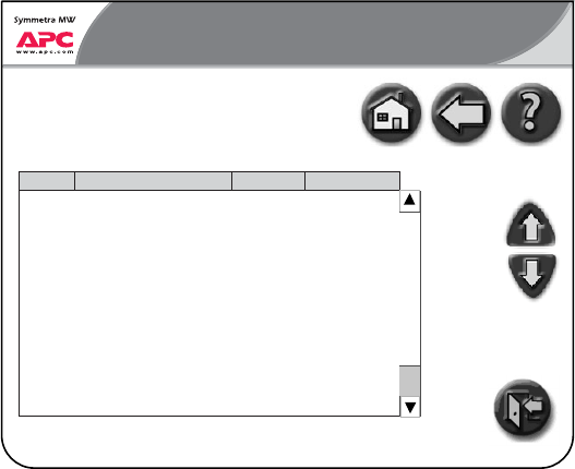
Home: Press to go to the UPS Summary screen.
Back: Press to go to previous screen.
Help: Press to access further details on current screen.
Page Up: Press to go to previous screen on same subject (only visible when there are
more screens on the same subject).
Page Down: Press to go to next screen on same subject (only visible when there are
more screens on the same subject).
Password logout: Press to log out from password protected screens.
Delta Inverter
Main Inverter
~
~

UPS Display: Display Symbols and Buttons
4 Symmetra® MW with Internal Bypass Static Switch - User Guide - 990-1756A-001
Buttons
Press this button to switch ON the module.
Press this button to switch OFF the module.
EMO (Emergency Module OFF) button:
Use in emergency situations to shut down the UPS. When the EMO button is engaged on
the UPS, AC and DC input and output are disabled.
OFF
EMO
Symmetra® MW with Internal Bypass Static Switch - User Guide - 990-1756A-001 5
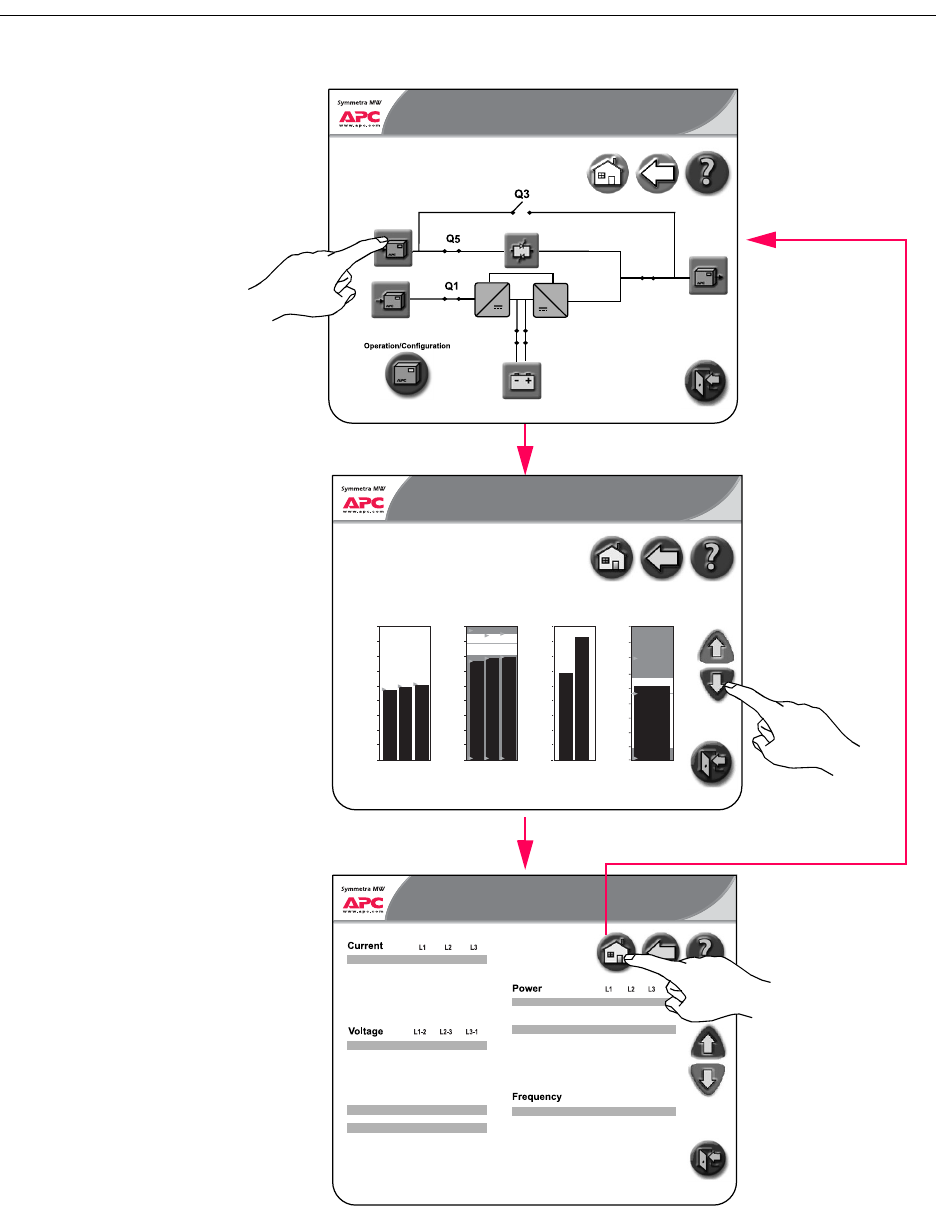
UPS Summary Screen
The LCD touch-screen UPS display is the user interface. It is used to configure the UPS, monitor the
system, and change the settings. The display also provides the user with audible and visual alarms.
The UPS display is organized hierarchically and the UPS Summary screen is the apex of the
hierarchy. To navigate to the UPS Summary screen, touch the house icon in the upper right corner of
the screen. The UPS Summary screen gives access to additional screens as shown below.
Normal Normal
NormalNormal
Normal
~~
Normal
UPS Summary
Normal
Operation/Configuration
Bypass
Summary
Operation/
Configuration
Battery
Summary
Input
Summary
Output
Summary
Note
The screens on the following pages are examples only. All values are not shown.
6 Symmetra® MW with Internal Bypass Static Switch - User Guide - 990-1756A-001
Input Summary Screens
The three Input Summary screens provide input-specific status of voltage, power, current, frequency,
etc.
Normal
~~
Q7 Q8
Normal
0:00 AM
Q2
UPS Summary
Output
Current
Current high
THD
THD high
THD low
Crest factor
Crest factor high
Active power
Active power high
Apparent power
Apparent power high
Power factor
Total active power
Total apparent power
Frequency
Frequency high
Frequency low
Tolerance
Mains SSW
Mains SSW high
Page 2 of 3
Voltage
Voltage high
Voltage low
THD
THD high
Voltage tolerance
Waveform tolerance
Tolerance conditions
Temperature
22.6
90.2
4.0
1.0
2.24
2.17
410
700
320
700
1.0
410
700
320
700
1.0
402
701
312
702
1.0
700
518
47.9
54.1
45.9
2.0
242.5
260.2
199.8
3.1
3.0
0.0
247.7
265.1
206.3
4.0
3.9
0.0
252.7
270.1
211.5
5.0
4.9
0.0
10
10
17.4
77.8
4.9
1.0
2.27
2.2
12.4
72.4
6.1
5.9
1.0
2.37
2.3
Normal
0:00 AM
Normal
Normal
Input Summary 5.40 PM
A
A
%
%
%
V
V
V
%
%
%
%
%
kW
kW
kVA
kVA
kW
kVA
Hz
Hz
Hz
%
129
127
oF
oF
Normal
Normal
Input Summary
5.40 PM
Page 1 of 3
587
522
456
391
326
262
196
130
65
L1 L2 L3
0
13 13 13
Current
A
495
440
365
330
275
220
165
110
55
0
450 453
Total Power
kW kVA
607
540
472
405
337
270
202
135
67
L1-2 L2-3 L3-1
0
Voltage
V
259 264 263
55.0
54.0
53.0
52.0
51.0
50.0
49.0
48.0
47.0
45.0
46.0
Frequency
Hz
259
Voltage
200.0
-200.0
0.0
Time (ms)
Current
Voltage
200.0
-200.0
0.0
0.0 5.0 10.0
Time (ms)
15.0
Current
Normal
Normal
Input Summary 5.40 PM
Page 3 of 3
Refresh Data
The black bars represent real-time
data. Yellow triangles represent the
maximum values recorded to date
and blue triangles represent the
minimum values recorded to date.
These values will be reset when the
input statistics are reset
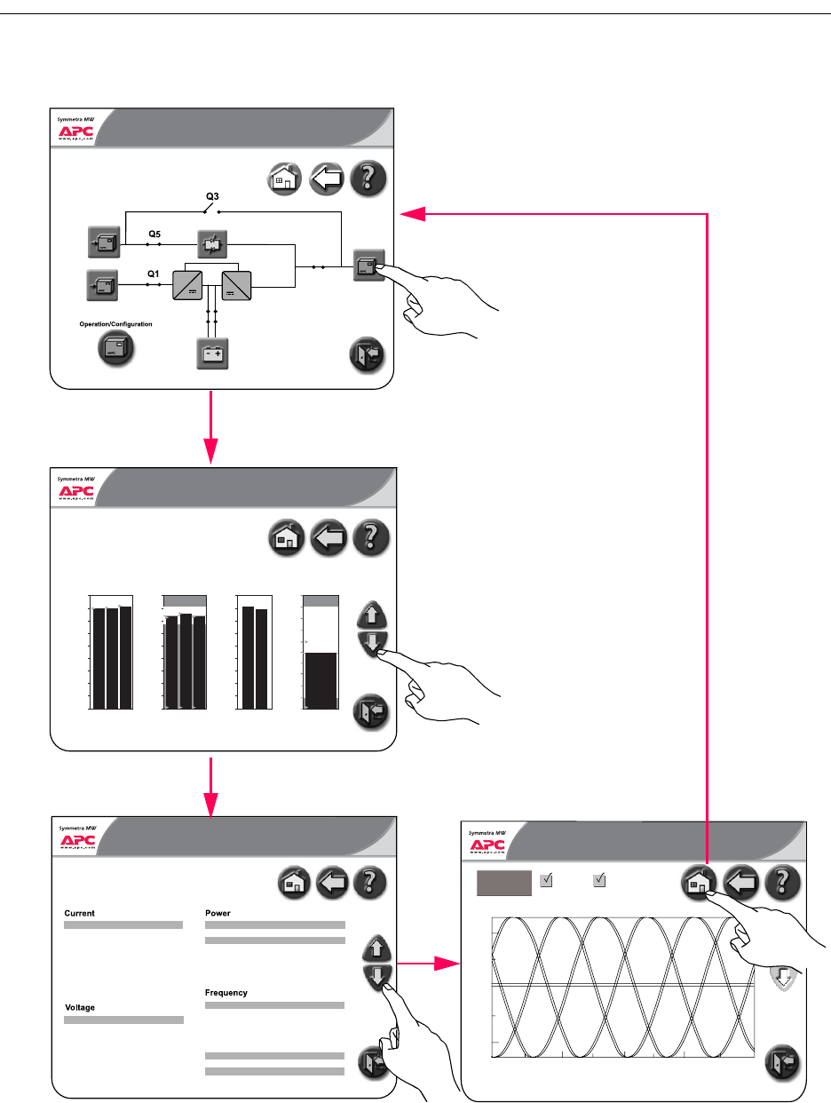
Symmetra® MW with Internal Bypass Static Switch - User Guide - 990-1756A-001 7
Output Summary Screens
The three Output Summary screens provide output-specific status of voltage, power, current,
frequency, etc.
Normal
~~
Q7 Q8
Normal
0:00 AM
Q2
UPS Summary
Normal
Normal
Output Summary
5.40 PM
Page 1 of 3
587
522
456
391
326
262
196
130
65
L1 L2 L3
0
13 13 13
Current
A
495
440
365
330
275
220
165
110
55
0
450 453
Total Power
kW kVA
607
540
472
405
337
270
202
135
67
L1-2 L2-3 L3-1
0
Voltage
V
259 264 263
55.0
54.0
53.0
52.0
51.0
50.0
49.0
48.0
47.0
45.0
46.0
Frequency
Hz
259
L1 L2 L3 L1 L2 L3
L1-2 L2-3 L3-1
Current
Current high
Peak current
Peak current high
THD
THD high
Crest factor
Crest factor high
Active power
Active power high
Apparent power
Apparent power high
Power factor
Total active power
Total apparent power
Frequency
Frequency high
Frequency low
Tolerance
Load
Load high
Total load
Total load high
Page 2 of 3
Voltage
Voltage high
Voltage low
THD
THD high
Voltage tolerance
Waveform tolerance
Tolerance conditions
Load
57.0
60.0
20.0
59.4
3.9
3.8
2.1
2.03
380
700
700
690
0.92
381
701
692
682
0.81
382
702
694
684
0.82
200
150
51.4
54.2
45.8
2.0
220.5
260.0
200.0
2.7
221.0
261.0
201.0
3.6
222.0
262.0
202.0
4.8
4.6
5
6
29
59.0
63.0
19.5
59.9
4.8
4.7
2.13
2.06
62.0
66.0
20.0
60.4
5.8
5.7
2.23
2.16
Normal
0:00 AM
Normal
Normal
Output Summary 5.40 PM
A
A
A
A
%
%
V
V
V
%
%
%
%
kW
kW
kVA
kVA
kW
kVA
Hz
Hz
Hz
%
60.0
58.0
68.0
66.0
78.0
76.0
142.0
250.0
%
%
%
%
Voltage
200.0
-200.0
0.0
Time (ms)
Current
Voltage
200.0
-200.0
0.0
0.0 5.0 10.0
Time (ms)
15.0
Current
Normal
Normal
Output Summary
5.40 PM
Page 3 of 3
Refresh Data
The black bars represent real-time
data. Yellow triangles represent the
maximum values recorded to date
and blue triangles represent the
minimum values recorded to date.
These values will be reset when the
output statistics are reset
8 Symmetra® MW with Internal Bypass Static Switch - User Guide - 990-1756A-001
Bypass Summary Screens
The two Bypass Summary screens provide status of voltage, power, current, frequency, etc.
Normal
~~
Q7 Q8
Normal
0:00 AM
Q2
Bypass Summary
Normal
Normal
Bypass Summary
5.40 PM
Page 1 of 2
110
88
86
73
61
49
37
24
12
L1 L2 L3
0
59 61 63
Current
A
127
112
108
84
70
56
42
20
14
0
83 118
Total Power
kW kVA
336
236
207
177
140
110
90
59
30
L1-2 L2-3 L3-1
0
Voltage
V
200 203 205
80.0
57.8
55.6
53.3
51.0
40.9
46.7
44.4
42.2
40.0
Frequency
Hz
51,8
The black bars represent real-time
data. Yellow triangles represent the
maximum values recorded to date
and blue triangles represent the
minimum values recorded to date.
These values will be reset when
the bypass statistics are reset
L1 L2 L3
Output
Current
Current high
Peak Current
Peak Current high
Crest factor
Crest factor high Power factor
Active power
Active power high
Apparent power
Apparent power high
Total active power
Total active power high
Total apparent power
Total apparent power high
Frequency
Frequency high
Frequency low
Load
Load high
Total load
Total load high
Page 2 of 2
Voltage
Voltage high
Voltage low
THD
Load
200.0
500.0
200.0
300.0
0.0
0.0 0.5
100
200
200
200
0.5
100
200
200
200
0.5
100
200
200
200
200
200
200
0
60.0
61.0
59.0
xxx.0
490.0
470.0
5.0
xxx.0
490.0
470.0
5.0
xxx.0
490.0
470.0
5.0
200.0
500.0
200.0
300.0
0.0
0.0
200.0
500.0
200.0
300.0
0.0
0.0
Normal
0:00 AM
Normal
Ready
Bypass Summary 2.07 PM
A
A
A
A
V
V
V
%
kW
kW
kW
kW
kW
kW
kW
kW
kW
Hz
Hz
Hz
Mains SSW
Mains SSW High
68
68
¡ F
¡ F
10.0
99.0
10.0
99.0
10.0
99.0
0.0
0.0
%
%
%
%
Temperature

Symmetra® MW with Internal Bypass Static Switch - User Guide - 990-1756A-001 9
Battery Summary Screens
The three Battery Summary screens provide battery-specific status of voltage, current, run-time
remaining, temperature, power, etc.
Normal
~~
Q7 Q8
Normal
0:00 AM
Q2
UPS Summary
Normal
Normal
Battery Summary 5.40 PM
Page 1 of 3
200
20
-160
-340
-520
-700
-880
-1060
-1240
Batt 1 Batt 2 Batt 1 Batt 2
-1420
32 37
Current
A
495
440
385
330
275
220
165
110
55
0
Voltage
V
435 435
Runtime remaining
12 m 0 s
-1600
Output
Battery 1
Voltage
Voltage high
Voltage low
Current
Current high discharge
Battery 2
Voltage
Voltage high
Voltage low
Current
Current high discharge
Settings
Min. voltage: warning
Min. voltage: shutdown
Max voltage: warning
Max voltage: shutdown
Boost charge
Auto boost charge
Nominal charge
Boost charge
Estimated charge time
Estimated charge %
Batt 1 charge current high
Batt 2 charge current high
Battery
Max battery
Battery high
Battery low
Battery charge
Time on battery
Runtime remaining
Total time on battery
Total # of times on battery
Page 2 of 3
Statistics
Charge
Temperature
Voltage and Current
false
false
420
450
65
100
-90.0
-90.0
100
86
104
86
440.0
450.0
420.0
57.2
119.5
451.0
460.0
420.0
51.5
120.0
370
320
460
475
Normal
0:00 AM
Normal
Normal
2.08 PM
V
V
V
A
A
V
V
V
A
A
V
V
V
V
V
V
m
%
A
A
o
F
o
F
o
F
o
F
Battery power
Battery power high discharge
Battery power high charge
Power
0
0
0
kW
kW
kW
Floating
0
300 m 0
0
0
s
s
m
Battery Summary
100.0
0.0
50.0
0.0 50.0 100.0
Time (hours)
Temperature
Normal
Normal
Normal
Battery Summary 5.40 PM
Page 3 of 3
Refresh Data
The curve shows the battery
The black bars represent real-time
data. Yellow triangles represent the
maximum values recorded to date
and blue triangles represent the
minimum values recorded to date.
These values will be reset when the
battery statistics are reset
10 Symmetra® MW with Internal Bypass Static Switch - User Guide - 990-1756A-001
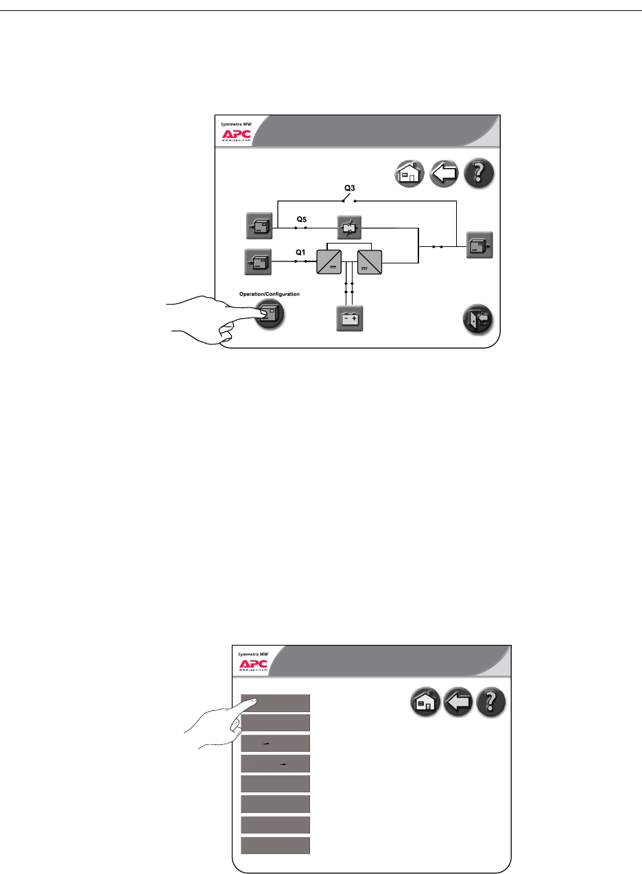
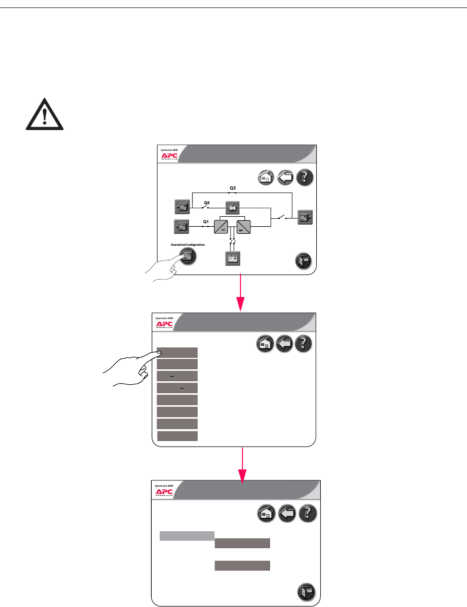
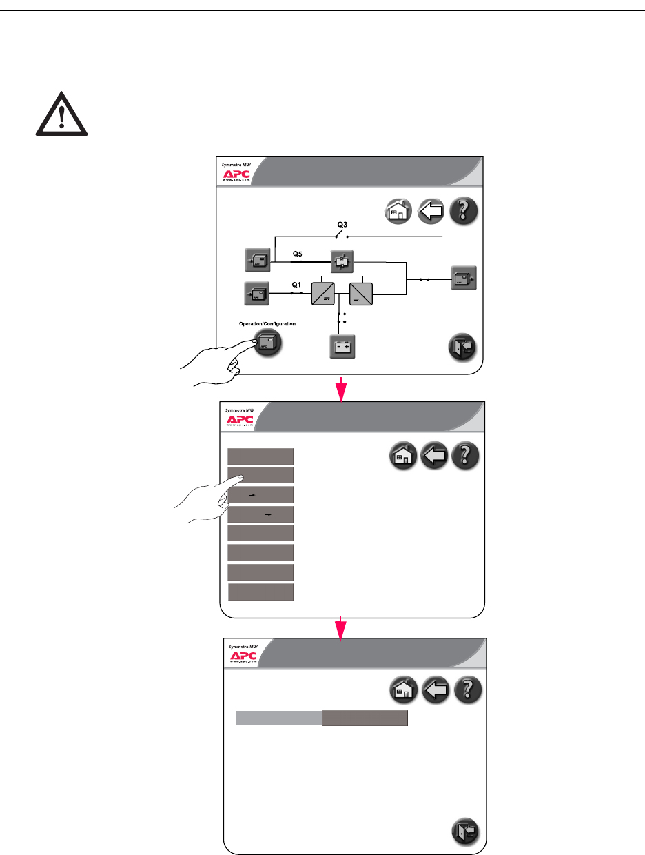
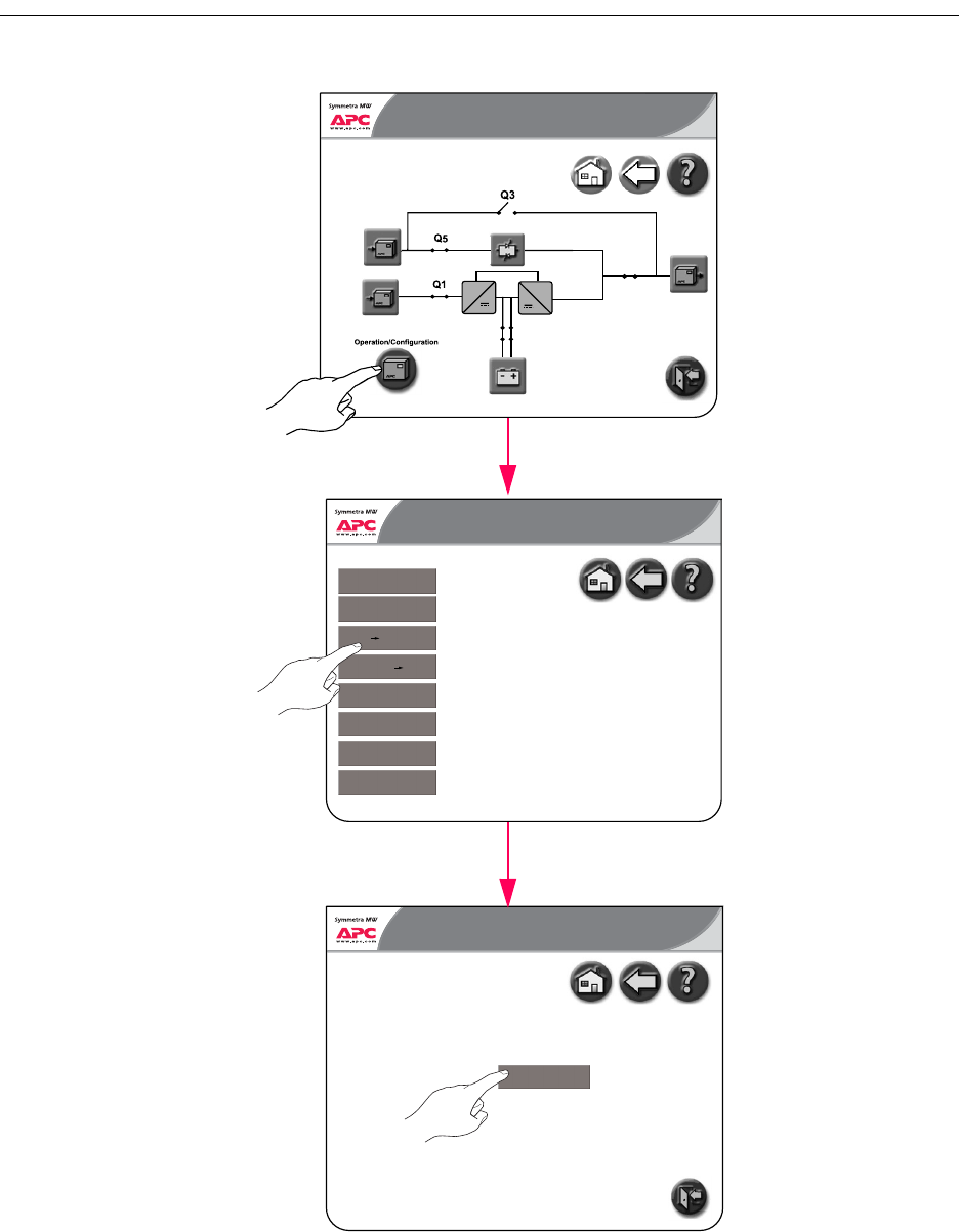
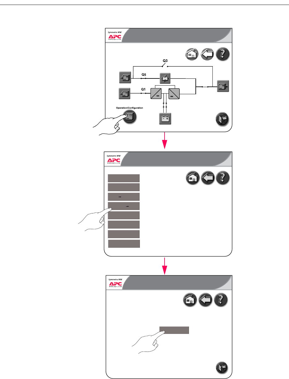
Operation Screen
The Operation screen permits system operation and monitoring, and provides the ability to change
display settings (as illustrated in the following menus).
Push the Operation/Configuration button to open the Operation screen.
The Operation screen leads to the following screens:
– UPS Start-Up screen
– UPS Shutdown screen
– Online to Static Bypass screen
– Static Bypass to Online screen
– Network Configuration screens
– User Configuration screens
– View Event Log screen
– Predictive Maintenance screens
Normal
~~
Q7 Q8
Normal
0:00 AM
Q2
UPS Summary
Normal
5.40 PM
Startup
Shutdown
Network Configuration
User Configuration
View Event Log
Predictive Maintenance
Static Bypass Online
Online Static Bypass
Transfer from manual bypass to online
Transfer from online to manual bypass
Transfer from online to static bypass
Transfer from static bypass to online
Operation
Normal
Symmetra® MW with Internal Bypass Static Switch - User Guide - 990-1756A-001 11
UPS Start-Up Screen
From the UPS Start-Up screen, the power flow can be transferred from Manual Bypass to Online
Operation.
The UPS Start-Up screen shows a list of actions, which need to be completed in order to start up the
UPS from Manual Bypass Operation. The actions are initially indicated in red to show that they have
not yet been completed. A yellow bar will highlight the actions in the order in which they need to be
completed. As actions are completed they will change to green.
The Start-Up procedure is described in “System Start-Up from Manual Bypass
Operation” .
Normal
Manual bypass/Off
UPS Startup 5.40 PM
Close Q1
Close breaker Q5
Charge DC Capacitors
Close battery breakers Q7 and Q8
Close breaker Q2
Initiate transfer to static bypass
Open breaker Q3
Push UPS "ON" button
Display will be off until Q1 closed
SSW input
Initiate Charge
Connect battery
UPS output
Initiate transfer
Manual bypass
UPS will power up
12 Symmetra® MW with Internal Bypass Static Switch - User Guide - 990-1756A-001
UPS Shutdown screen
The UPS Shutdown screen shows a list of actions, which need to be completed in order to shut down
the UPS. The actions are initially indicated in red to show that they have not yet been completed. A
yellow bar will highlight the actions in the order in which they need to be completed. As actions are
completed they will change to green.
The Start-Up procedure is described in “System Shutdown from Online to Manual
Bypass Operation” .
Normal
Normal
UPS Shutdown 5.40 PM
Initiate transfer to static bypass
Close breaker Q3
Open breaker Q5
Push UPS "OFF" button
Open breaker Q2
Open battery breakers Q7 and Q8
Open breaker Q1
Initiate transfer
Load will be on manual bypass
SSW input
UPS power down
UPS output
Isolate UPS from battery
UPS input
Symmetra® MW with Internal Bypass Static Switch - User Guide - 990-1756A-001 13
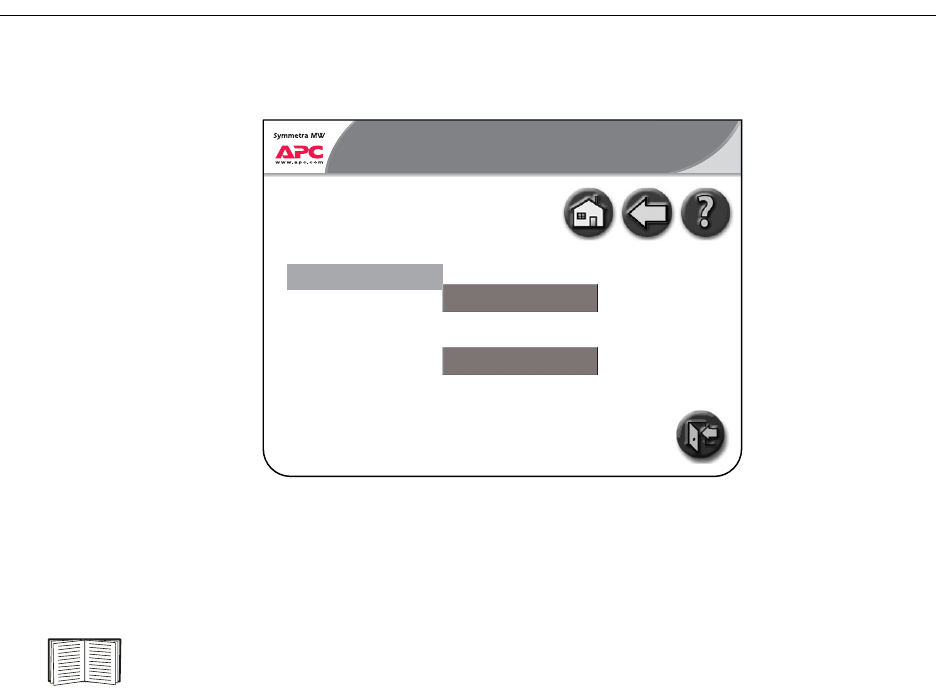
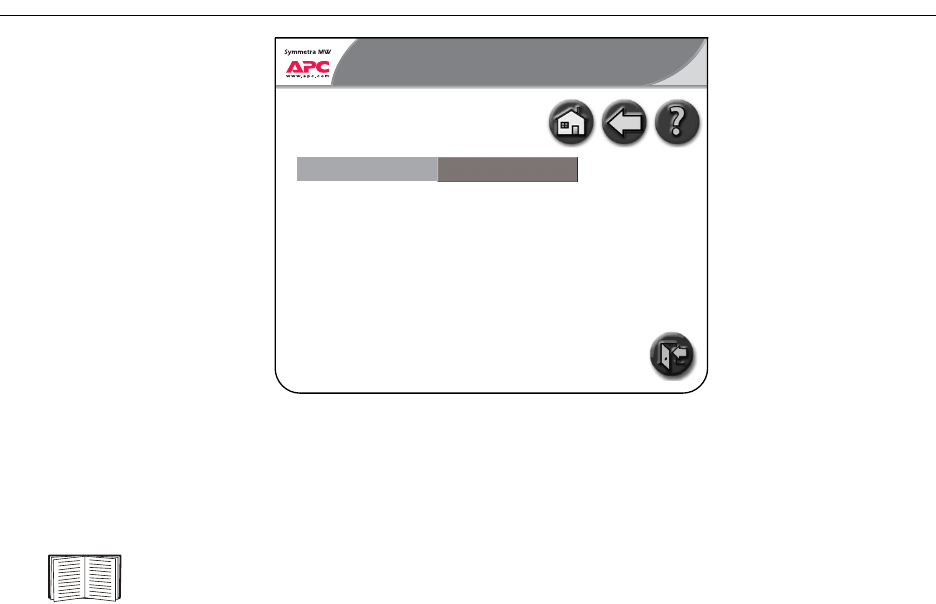
Online to Static Bypass Screen
From the Online to Static Bypass screen, the power flow can be transferred from Online to Static
Bypass Operation.
Initiate transfer to static bypass
In static bypass the load is powered directly by utility power.
There will be no UPS backup.
Normal
Normal
0:00 AM
Online to Static Bypass
Initiate transfer
14 Symmetra® MW with Internal Bypass Static Switch - User Guide - 990-1756A-001
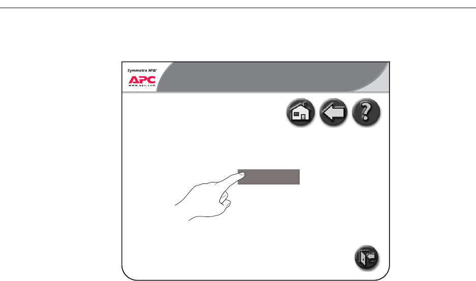
Static Bypass to Online Screen
From the Static Bypass to Online screen, the power flow can be transferred from Static Bypass to
Online Operation.
Normal
Initiate transfer to online
Static Bypass to Online 0:00 AM
Initiate transfer
Static Bypass
Symmetra® MW with Internal Bypass Static Switch - User Guide - 990-1756A-001 15
Network Configuration Screens
There are five Network Configuration screens that will be described below:
• Network Settings screen
• E-mail Settings screen
• SNMP Settings screen
• Remote Monitoring Service Settings screen
• APC ISX Manager Settings screen
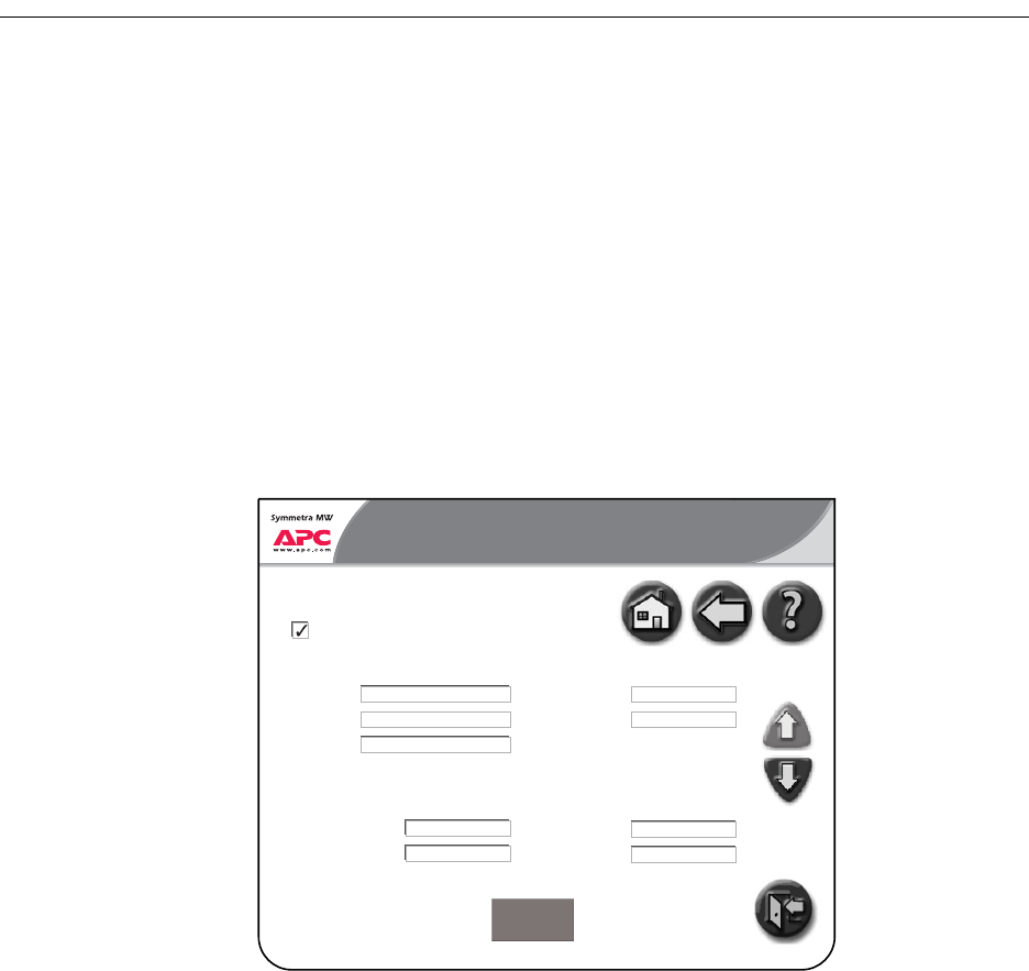
Network Settings screen
All network settings information must be provided before any network functions can be used.
• Enable Network: Use the checkbox to connect or disconnect the UPS from the network.
IP Settings.
• IP address: The static IP address.
• Subnet Mask: The subnet mask for the network segment that the UPS is on.
• Gateway: The network gateway for the segment that the UPS is on.
DNS Settings.
• Primary DNS server: The IP address of the DNS server to be used by the UPS (optional).
• Secondary DNS server: The IP address of a DNS server to use if the primary server is not
available (optional).
Normal
Normal
Network Configuration
Network Settings
5.39 PM
Page 1 of 5
IP address
Subnet mask
Gateway
Enable network
Apply Changes
xxx.xxx.xxx.xxx
xxx.xxx.xxx.x
xxx.xxx.xxx.x
UPS1
IP Settings Host Name Settings
DNS Settings
Primary DNS server
Secondary DNS server
xxx.xxx.xxx.xxx
xxx.xxx.xxx.xxx
company.com
Hostname
Domain name
xxxxxx.xxxx@xxx.xx
SMTP Settings
company.com
From address
SMTP server
UPS Display: Network Configuration Screens
16 Symmetra® MW with Internal Bypass Static Switch - User Guide - 990-1756A-001
Host Name Settings.
• Host name: The network host name for the system. This uniquely identifies the system on the
network. Standard letters (a-z and A-Z), digits (1-9) and hyphen (-) can be used.
• Domain name: The DNS network domain that the UPS is on. Standard letters (a-z and A-Z),
digits (1-9) and hyphen (-) can be used.
SMTP Settings.
• From address: The from address to be used when sending e-mails.
• SMTP server: The SMTP server responsible for sending e-mails.
•
Select the Apply Changes button when all information has been entered.
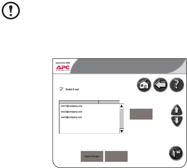
E-mail Settings screen
From the E-mail Settings screen, configure the e-mail recipients to be notified of alarms, which may
occur on the system. The severity of the alarms may be informational, warning or severe and can be
specified for each E-mail recipient. Up to 25 e-mail recipients can be entered.
• Enable E-mail: Enable the e-mail notifications by selecting this checkbox.
• To add a new e-mail recipient, touch the Add New button, type in the e-mail address and specify
the minimum severity of alarm.
• To edit or delete an e-mail recipient, select the recipient as they appear in the recipient list.
Choose to either update or delete the recipient.
Note
Network Settings information must be configured prior to enabling e-mail.
Normal
Normal
Network Configuration 5.34 PM
Page 2 of 5
Add new
Send Test E-mail
1 of 25 addresses
Informational
Warning
Severe
E-mail Recipient(s) Severity
E-mail Settings
UPS Display: Network Configuration Screens
Symmetra® MW with Internal Bypass Static Switch - User Guide - 990-1756A-001 17
• Apply Changes: Select this button after all changes have been made. All entries will appear in
red until Apply Changes is pressed.
• Send Test E-mail: When this button is pressed, a test E-mail is sent to all configured E-mail
recipients. This button can be used to validate the e-mail settings.
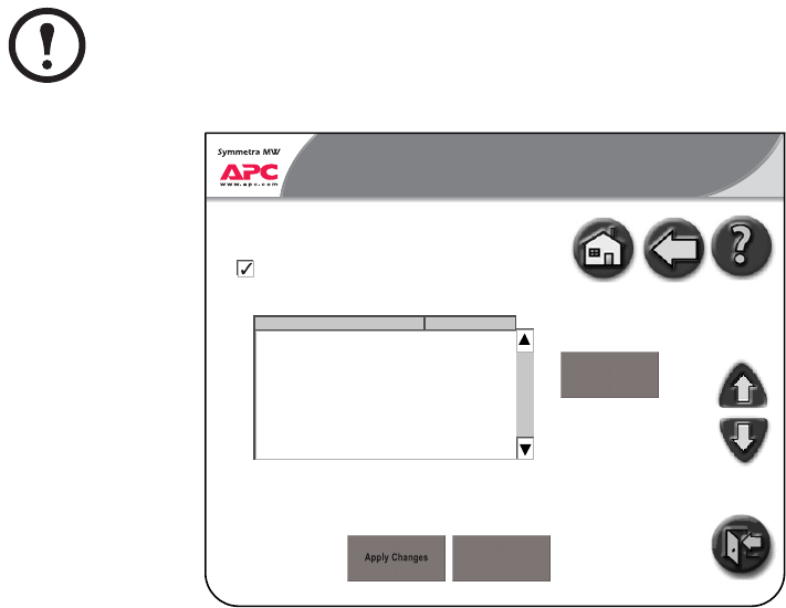
SNMP Settings screen
The UPS can be set to send SNMP traps if UPS alarm conditions occur, and when the conditions
return to normal afterwards. Each trap contains a description of the alarm condition. Up to 10 Trap
Receivers can be entered.
The Trap Receiver must have the APC PowerNet MIB (version 3.6.1 or later). The latest version of
the PowerNet MIB can be downloaded from www.apc.com.
• Enable SNMP: Enable the SNMP functionality by selecting this checkbox.
• To add a new Trap Receiver, touch the Add New button, type in the address and specify the
minimum severity of alarm.
• To edit or delete a Trap Receiver, select the recipient as they appear in the recipient list. Choose
to either update or delete the Trap receiver.
• Apply Changes: Select this button after all changes have been made. All entries will appear in
red until Apply Changes is pressed.
• Send Test SNMP: When this button is pressed, a test trap is sent to all configured Trap
Receivers. This button can be used to validate SNMP settings.
Note
Network Settings must be configured prior to configuring the SNMP Settings.
Normal
Normal
Network Configuration
SNMP Settings
5.34 PM
Page 3 of 5
Enable SNMP
Add new
Send Test SNMP
1 of 10 trap receivers
Informationalxxx.xxx.xxx.xx
Trap Receiver(s) Severity
UPS Display: Network Configuration Screens
18 Symmetra® MW with Internal Bypass Static Switch - User Guide - 990-1756A-001
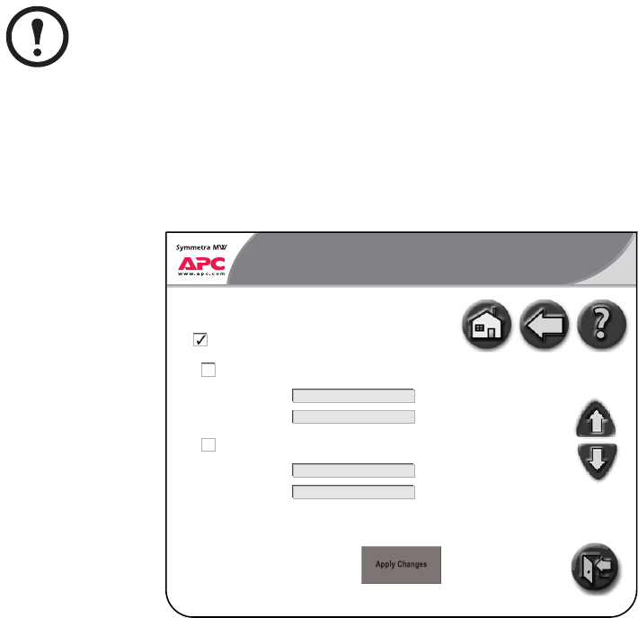
Remote Monitoring Service Settings screen
The APC Remote Monitoring Service (RMS) is an APC professional service which securely
monitors customer’s power systems and surrounding environment from a remote 24×7 operation
center, responding to events according to a pre-defined customer escalation procedure. Visit
rms.apc.com to learn more about this service.
• Enable APC RMS: Select this checkbox to start using the service. Once selected, information
about your UPS will periodically be sent to APC’s Remote Monitoring Service.
The APC Remote Monitoring Service uses HTTP protocol to post information to its database. If a
proxy server is used as Internet connection method, then the required proxy server port settings must
be specified (a proxy server acts as an agent between a workstation user or other networked device
and the Internet so that the security, administrative control and caching service can be regulated).
• Use Proxy: Select this checkbox if the Internet connection method uses a HTTP proxy server to
connect to the Internet.
• Proxy server address: Enter the fully qualified IP address or fully qualified domain name of the
proxy server. If you do not know the server address or port number, contact your network
administrator.
• Proxy server port: Enter the port number of the proxy server.
• Use authentication: Select this checkbox if the proxy server requires a login. Then specify a
Proxy server login (user name) and a Proxy server password.
•
Note
Network settings must be configured before the remote monitoring feature can be used.
Normal
Normal
Network Configuration
Remote Monitoring Service Settings
5.39 PM
Page 4 of 5
Proxy server address
Proxy server port
Enable APC RMS
Use proxy
xxxx
Proxy server login
Proxy server password
Use authentication
UPS Display: Network Configuration Screens
Symmetra® MW with Internal Bypass Static Switch - User Guide - 990-1756A-001 19
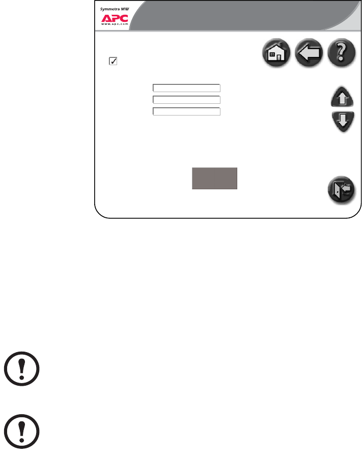
APC ISX Manager Settings screen
The following settings have to be configured for the Symmetra MW to be discovered by the APC
ISX Manager:
• Community name: Select the Enable ISX manager discovery check-box
• System Location (optional)
• System Contact (optional)
System Contact (optional)
Note
By default the community string is set to public.
Note
Select the Apply Changes button after the APC ISX Manager screen has been completed.
Normal
Normal
Network Configuration
APC ISX Manager Settings
5.34 PM
Page 5 of 5
Enable ISX Manager Discovery
Community Name
System Location
System Contact
xxxxxx
xxxxxx
xxxxx
Apply Changes
20 Symmetra® MW with Internal Bypass Static Switch - User Guide - 990-1756A-001
User Configuration Screens
There are five User Configuration screens:
• Touch-Screen Settings screen
• Password Settings screen
• Modbus Settings screen
• Regional Settings screen
• Battery Test screen
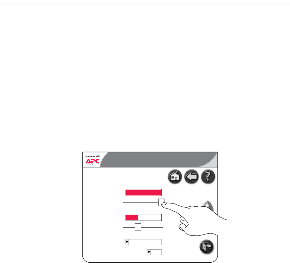
Touch-Screen Settings screen
The Touch-Screen Settings screen is used to customize the brightness, contrast and backlight of the
display.
• Brightness: Put the finger on the indicator and slide to the left or right to the desired setting.
• Contrast: Put the finger on the indicator and slide to the left or right to the desired setting.
• Backlight mode: The backlight mode’s default setting is that the light goes off after 5 minutes of
inactivity.
• Backlight timeout (minutes): The display backlight can be set to be always on or to turn off after
a certain period of screen inactivity.
Normal
0100%
Brightness
100 %
0100%
Contrast
35%
Normal
User Configuration 2:27 PM
Always on
5
Touch-Screen Settings
Page 1 of 5
Backlight mode
Backlight timeout (minutes)
UPS Display: User Configuration Screens
Symmetra® MW with Internal Bypass Static Switch - User Guide - 990-1756A-001 21
Password Settings screen
Some of the UPS Display screens (primarily configuration screens) are protected by a password.
On installation the password is set to “apc.” For security reasons, it is recommended to change the
password.
• Enter current password: Enter the current password.
• Enter new password: Enter the new password.
• Re-enter the new password: Re-enter the password to validate the password.
Modbus Settings screen
The Modbus Settings screen allows monitoring of the UPS system by a Building Management
System (BMS).
Note
If you forget the password, contact your APC service representative who will be able to
help you.
Normal
Normal
User Configuration
Password Settings
5.39 PM
Page 2 of 5
Enter current password
Enter new password
Re- enter new password
Apply Changes
xxxx
xxxxxxxx
xxxxxxxx
Normal
Normal
User Configuration
Modbus Settings
5.39 PM
Page 3 of 5
BMS modbus RTU address
Communication Settings
Baud rate
Parity
Apply Changes
xxxx
xxxx
xxxx
UPS Display: User Configuration Screens
22 Symmetra® MW with Internal Bypass Static Switch - User Guide - 990-1756A-001
• BMS modbus RTU address: The modbus slave address of the UPS device.
•Baud rate
• Parity
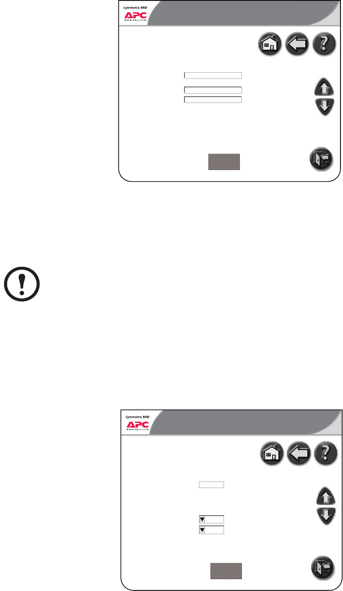
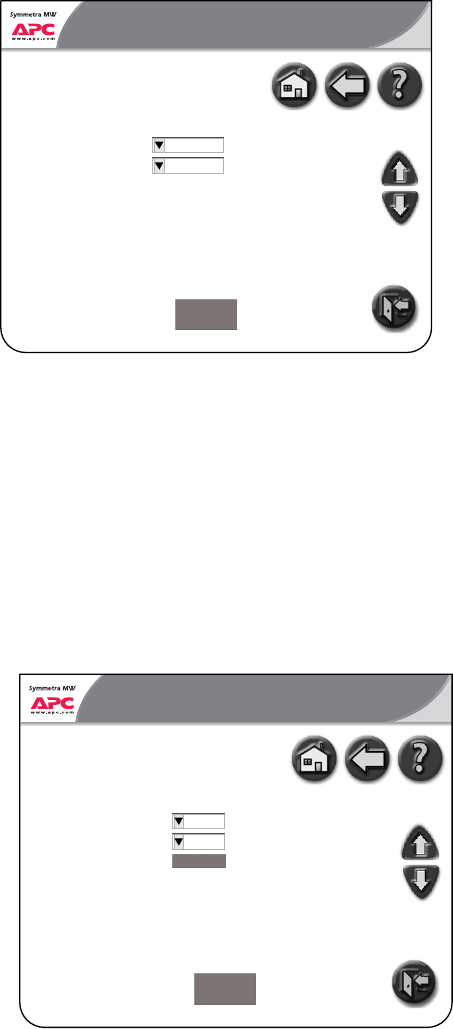
Regional Settings screen
• Temperature unit: Select Celsius or Fahrenheit.
• Date format: Select the preferred date format.
• Apply Changes: Press the Apply Changes button when selections have been made.
Battery Test screen
From the Battery Test screen two different battery tests can be performed and the battery monitor can
be reset.
Normal
Normal
User Configuration
Regional Settings
5.39 PM
Page 4 of 5
Temperature unit
Date format
Apply Changes
xxxx
MM_DD_YYYY
Normal
Normal
User Configuration
Battery Test
5.39 PM
Page 5 of 5
Battery monitor test
Battery capacity test
Battery monitor reset
Apply Changes
xxxx
xxxx
Reset
UPS Display: User Configuration Screens
Symmetra® MW with Internal Bypass Static Switch - User Guide - 990-1756A-001 23
• Battery monitor test: Setting this value to True results in an automatic battery monitor test being
performed at regular intervals specified by the Service Engineer. The three options are:
– Auto battery test - every (N) week(s).
– Auto battery test - on one day of the week.
– Auto battery test - at a specific time of the day.
• Battery capacity test: Setting this value to True results in the batteries being discharged until a
Battery Low Voltage Level is reached. This test can only be performed manually. The test is
used to cycle the batteries in order to calibrate the backup time with the current load and battery
modules installed.
• Battery monitor reset: In the event of a weak battery or another battery problem, use this button
to reset the battery monitor.
24 Symmetra® MW with Internal Bypass Static Switch - User Guide - 990-1756A-001
Event Log Screen
The Event Log screen contains a detailed record of the system’s last 1024 events. This includes
operation mode changes, system alarms, etc.
• Refresh: Select the Refresh button to update the Event Log.
• Stop (only visible during update): Select this button to stop the event log downloading.
• E-mail Event Log: Press this button to e-mail the event log to a specific e-mail address. Enter in
the e-mail address and press the Send button.
SeveritySeverityNo.No. Event DescriptionEvent Description Param
ParamParamParam Date & TimeDate & Time
Bypass fast error detected
Bypass input frequency fault
Bypass static switch temperature fault
Bypass static switch fault
Bypass static switch backfeed protect on
Bypass static switch thyristor fault
Bypass static switch fuse blown
Bypass static switch fan fault
Bypass isolation transformer temp. high
Bypass voltage low
Bypass synchonization error
MC isolated SELV PSU fault
ABUS terminator fault
Discharging batteries
Section is disabled
1
1
1
1
1
1
1
1
1
1
1
1
1
1
1
01–27–2004 11:00:41.0
03–01–2004 11:10:41.0
06–02–2004 11:14:41.0
12–02–2004 11:30:47.0
06–27–2004 11:40:45.0
06–27–2004 13:00:50.0
06–27–2004 14:24:10.0
03–17–2004 15:24:11.0
04–14–2004 17:24:12.0
05–15–2004 18:24:10.0
06–30–2004 19:24:02.0
07–17–2004 20:30:10.0
08–13–2004 13:24:15.0
09–10–2004 13:24:15.0
10–27–2004 13:24:15.0
Severe
Severe
Severe
Severe
Severe
Severe
Severe
Severe
Severe
Severe
Severe
Severe
Severe
Severe
Severe
Data
DataDataData
Normal
Alarm: Severe
Event Log
E- mail Event LogRefresh
242 event(s) downloaded
1
2
3
4
5
6
7
8
9
10
11
12
13
14
15
0
0
Alarm: Severe
Event Log

Symmetra® MW with Internal Bypass Static Switch - User Guide - 990-1756A-001 25
Predictive Maintenance Screens
The Predictive Maintenance screens display the stress status and the Expected Remaining Lifetime
(ERL) of the critical components of the Symmetra MW UPS system.
There are five Predictive Maintenance screens:
• Inverter DC Capacitors screen
• Inverter AC Capacitors screen
• Top Fans screen
• Inverter Fans screen
• Main Static Switch Fans screen
Inverter DC Capacitors screen
The Inverter DC Capacitor screen displays the actual status and Expected Remaining Lifetime (ERL)
of the Inverter DC Capacitors. It is possible to sort the data on the screen by touching any of the
column labels.
• Stress Status: States the actual status of the Inverter DC Capacitors. The possible values are:
– Normal (displaying in green)
– Stressed (displaying in yellow)
– Major Stress (displaying in red)
• ERL (months): Predicts the expected remaining lifetime of the particular component.
Normal
Normal
Predictive Maintenance
Inverter DC Capacitors
5.39 PM
Page 1 of 5
TypeNumber Stress Status ERL (months)*
OK0046 DC Cap
OK0046 DC Cap
OK0046 DC Cap
OK0046 DC Cap
OK0046 DC Cap
OK0046 DC Cap
OK0046 DC Cap
OK0046 DC Cap
OK0046 DC Cap
OK0046 DC Cap
OK0046 DC Cap
OK0046 DC Cap
120
120
120
120
120
120
120
120
120
120
120
120
Normal
Normal
Normal
Normal
Normal
Normal
Normal
Normal
Normal
Normal
Normal
Normal
1
2
3
4
5
6
7
8
9
10
11
12
* ERL - Expected Remaining Lifetime

UPS Display: Predictive Maintenance Screens
26 Symmetra® MW with Internal Bypass Static Switch - User Guide - 990-1756A-001
Inverter AC Capacitors screen
The Inverter AC Capacitor screen displays the actual status and Expected Remaining Lifetime (ERL)
of the Inverter AC Capacitors. It is possible to sort the data on the screen by touching either of the
column labels.
• Stress Status: States the actual status of the Inverter AC Capacitors. The possible values are:
– Normal (displaying in green)
– Stressed (displaying in yellow)
– Major Stress (displaying in red)
• ERL (months): Predicts the expected remaining lifetime of the particular component.
Normal
Normal
Predictive Maintenance
Inverter AC Capacitors
5.39 PM
Page 2 of 5
TypeNumber Stress Status ERL (months)*
OK0046 AC Cap
OK0046 AC Cap
OK0046 AC Cap
OK0046 AC Cap
OK0046 AC Cap
OK0046 AC Cap
OK0046 AC Cap
OK0046 AC Cap
OK0046 AC Cap
OK0046 AC Cap
OK0046 AC Cap
OK0046 AC Cap
120
120
120
120
120
120
120
120
120
120
120
120
Normal
Normal
Normal
Normal
Normal
Normal
Normal
Normal
Normal
Normal
Normal
Normal
1
2
3
4
5
6
7
8
9
10
11
12
* ERL - Expected Remaining Lifetime

UPS Display: Predictive Maintenance Screens
Symmetra® MW with Internal Bypass Static Switch - User Guide - 990-1756A-001 27
Top Fans screen
The Top Fans screen displays the actual status and Expected Remaining Lifetime (ERL) of the Top
Fans. It is possible to sort the data on the screen by touching either of the column labels.
• Stress Status: States the actual status of the Top Fans. The possible values are:
– Normal (displaying in green)
– Stressed (displaying in yellow)
– Major Stress (displaying in red)
• ERL (months): Predicts the expected remaining lifetime of the particular component.
Normal
Normal
Predictive Maintenance
Top Fans
5.39 PM
Page 3 of 5
TypeNumber Stress Status ERL (months)*
490-00XX Top fan xxxx
490-00XX Top fan xxxx
490-00XX Top fan xxxx
490-00XX Top fan xxxx
490-00XX Top fan xxxx
490-00XX Top fan xxxx
490-00XX Top fan xxxx
490-00XX Top fan xxxx
490-00XX Top fan xxxx
490-00XX Top fan xxxx
490-00XX Top fan xxxx
490-00XX Top fan xxxx
120
120
120
120
120
120
120
120
120
120
120
120
Normal
Normal
Normal
Normal
Normal
Normal
Normal
Normal
Normal
Normal
Normal
Normal
1
2
3
4
5
6
7
8
9
10
11
12
* ERL - Expected Remaining Lifetime
UPS Display: Predictive Maintenance Screens
28 Symmetra® MW with Internal Bypass Static Switch - User Guide - 990-1756A-001
Inverter Fans screen
The Inverter Fans screen displays the actual status and Expected Remaining Lifetime (ERL) of the
Inverter Fans. It is possible to sort the data on the screen by touching either of the column labels.
• Stress Status: States the actual status of the Inverter Fans. The possible values are:
– Normal (displaying in green)
– Stressed (displaying in yellow)
– Major Stress (displaying in red)
• ERL (months): Predicts the expected remaining lifetime of the particular component.
Normal
Normal
Predictive Maintenance
Inverter Fans
5.39 PM
Page 4 of 5
TypeNumber Stress Status ERL (months)*
490-0039 PM Fan
490-0039 PM Fan
490-0039 PM Fan
490-0039 PM Fan
490-0039 PM Fan
490-0039 PM Fan
490-0039 PM Fan
490-0039 PM Fan
490-0039 PM Fan
490-0039 PM Fan
490-0039 PM Fan
490-0039 PM Fan
120
120
120
120
120
120
120
120
120
120
120
120
Normal
Normal
Normal
Normal
Normal
Normal
Normal
Normal
Normal
Normal
Normal
Normal
1
2
3
4
5
6
7
8
9
10
11
12
* ERL - Expected Remaining Lifetime

UPS Display: Predictive Maintenance Screens
Symmetra® MW with Internal Bypass Static Switch - User Guide - 990-1756A-001 29
Main Static Switch Fans screen
The Main Static Switch Fans screen displays the actual status and Expected Remaining Lifetime
(ERL) of the Main Static Switch Fans. It is possible to sort the data on the screen by touching either
of the column labels.
• Stress Status: States the actual status of the Main Static Switch Fans. The possible values are:
– Normal (displaying in green)
– Stressed (displaying in yellow)
– Major Stress (displaying in red)
• ERL (months): Predicts the expected remaining lifetime of the particular component.
Normal
Normal
Predictive Maintenance
Main Static Switch Fans
5.39 PM
Page 5 of 5
TypeNumber Stress Status ERL (months)*
490-00XX SSW Fan xxx
490-00XX SSW Fan xxx
490-00XX SSW Fan xxx
490-00XX SSW Fan xxx
490-00XX SSW Fan xxx
490-00XX SSW Fan xxx
490-00XX SSW Fan xxx
490-00XX SSW Fan xxx
490-00XX SSW Fan xxx
490-00XX SSW Fan xxx
490-00XX SSW Fan xxx
490-00XX SSW Fan xxx
120
120
120
120
120
120
120
120
120
120
120
120
Normal
Normal
Normal
Normal
Normal
Normal
Normal
Normal
Normal
Normal
Normal
Normal
1
2
3
4
5
6
7
8
9
10
11
12
* ERL - Expected Remaining Lifetime
Symmetra® MW with Internal Bypass Static Switch - User Guide - 990-1756A-001 31
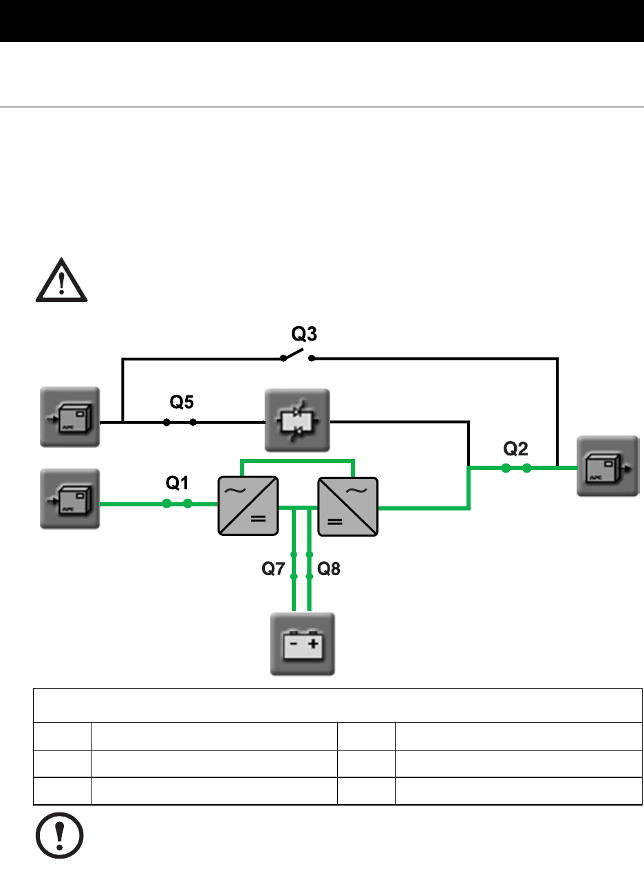
Operation Modes
On-line Operation
During on-line operation, the critical load is supported by the inverters. The main inverter controls
the output voltage and the delta inverter controls the input current. The delta inverter also provides
battery-charging current. While the UPS is running in this mode, a single-line diagram will appear on
the screen. The green line indicates the power flow from the utility supply through the UPS to the
load.
CAUTION!
Do not open Q2 when the UPS is in on-line operation, as this action may result in a load
drop or a failure of the UPS to support the load.
Breaker Identification
Q1 UPS input breaker Q5 Static bypass input breaker
Q2 UPS output breaker Q7 Battery breaker 1
Q3 Manual bypass breaker Q8 Battery breaker 2
Note
Only operate a breaker when the associated breaker lamp is on.
Battery
Main inverterDelta inverter
Bypass Static Switch
32 Symmetra® MW with Internal Bypass Static Switch - User Guide - 990-1756A-001
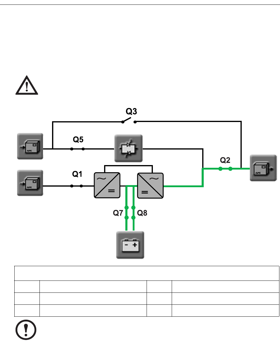
Battery Operation
During battery operation, the load is supported by the inverters. The inverters are supplied by battery
power, ensuring uninterrupted support to the load.
While the UPS is running in battery operation, a single-line diagram will appear on the screen with a
green line indicating the power flow from the batteries through the main inverter to the load for as
long as the batteries are energized.
CAUTION!
Do not open Q2, Q7 or Q8 when the UPS is in battery operation, as this action may result
in a load drop or a failure of the UPS to support the load.
Breaker Identification
Q1 UPS input breaker Q5 Static bypass input breaker
Q2 UPS output breaker Q7 Battery breaker 1
Q3 Manual bypass breaker Q8 Battery breaker 2
Note
Only operate a breaker when the associated breaker lamp is on.
Battery
Delta inverter Main inverter
Bypass Static Switch
Symmetra® MW with Internal Bypass Static Switch - User Guide - 990-1756A-001 33
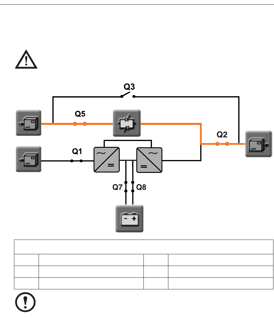
Bypass Operation
During bypass operation, the critical load is supplied directly by utility power. A single-line diagram
will appear on the screen with an orange line indicating the power flow through the Bypass SSW to
the load.
CAUTION!
Do not open Q2 or Q5 when the UPS is in bypass operation, as this action may result in a
load drop or a failure of the UPS to support the load.
Breaker Identification
Q1 UPS input breaker Q5 Static bypass input breaker
Q2 UPS output breaker Q7 Battery breaker 1
Q3 Manual bypass breaker Q8 Battery breaker 2
Note
Only operate a breaker when the associated breaker lamp is on.
Main inverterDelta inverter
Battery
Bypass Static Switch
34 Symmetra® MW with Internal Bypass Static Switch - User Guide - 990-1756A-001
Manual Bypass Operation
During manual bypass operation, the critical load is supplied directly by utility power, making it
possible to isolate the UPS and the Bypass Static Switch for maintenance.
A single-line diagram will appear on the screen, with an orange line indicating the power flow from
the utility to the load via the Q3 breaker.
Note
Battery power is not available as an alternate power source while the system is running
in manual bypass operation.
CAUTION!
Do not open Q3 when the UPS is in manual bypass operation, as this action may result in
a load drop or a failure of the UPS to support the load.
Breaker Identification
Q1 UPS input breaker Q5 Static bypass input breaker
Q2 UPS output breaker Q7 Battery breaker 1
Q3 Manual bypass breaker Q8 Battery breaker 2
Note
Only operate a breaker when the associated breaker lamp is on.
Main inverterDelta inverter
Bypass Static Switch
Battery
Symmetra® MW with Internal Bypass Static Switch - User Guide - 990-1756A-001 35
System Start-Up from Manual Bypass
Operation
If the UPS has been operating in manual bypass operation and no power is connected to the UPS, the
UPS display will be inactive. To re-start the system from manual bypass and achieve on-line
operation, close Q1 in the external maintenance bypass panel. This will power up the internal power
supply. Wait for the display to become active and follow the screen-prompted instructions.
CAUTION!
Follow these instructions carefully. Failure to do so could result in equipment damage.
Normal
5.40 PM
Operation
Startup
Shutdown
Network Configuration
User Configuration
View Event Log
Predictive Maintenance
Static Bypass Online
Online Static Bypass
Transfer from manual bypass to online
Transfer from online to manual bypass
Transfer from online to static bypass
Transfer from static bypass to online
Manual Bypass/Off
Normal
~~
Q7 Q8
Q2
Manual bypass/Off
0:00 AM
UPS Summary
Select Operation/
Configuration
Follow the start-up
instructions on the screen.
Active commands initially appear in
red. Once a command has been
carried out successfully, its text will
change to green. Important: After
pressing “Initiate charge” in step 2,
wait until the green lights go on
alongside battery breakers Q7 and
Q8 on front of the Battery Breaker
Box before closing the breakers.
Select Start-up
Normal
Manual bypass/Off
UPS Startup 5.40 PM
Close Q1
Close breaker Q5
Charge DC Capacitors
Close battery breakers Q7 and Q8
Close breaker Q2
Initiate transfer to static bypass
Open breaker Q3
Push UPS "ON" button
Display will be off until Q1 closed
SSW input
Initiate Charge
Connect battery
UPS output
Initiate transfer
Manual bypass
UPS will power up
Operation Modes: System Start-Up from Manual Bypass Operation
36 Symmetra® MW with Internal Bypass Static Switch - User Guide - 990-1756A-001
System Start-Up from Manual Bypass to Online Operation of single mains/utility
system - Step-by-Step
1. Close Q1 in the external maintenance bypass panel to power up the internal power supply. Wait
for the display to become active.
2. Press Operation/Configuration on the UPS Summary screen on the UPS display.
3. Press Startup on Operation screen.
4. Press “Initiate Charge” on the UPS display to initiate the charging of the UPS DC capacitors.
5. When the green lights H7 and H8 are illuminated, close battery breakers Q7 and Q8 to connect
the battery system.
6. Close Q2 breaker.
7. Press “Initiate Transfer” on the UPS display to transfer to Static Bypass Operation.
8. Open maintenance bypass breaker Q3.
9. Push ON button on the UPS to transfer to Online Operation
System Start-Up from Manual Bypass to Online Operation of dual mains/utility
system - Step-by-Step
1. Close Q1 and Q5 in the external maintenance bypass panel to power up the internal power
supply. Wait for the display to become active.
2. Press Operation/Configuration on the UPS Summary screen on the UPS display.
3. Press Startup on Operation screen.
4. Press “Initiate Charge” on the UPS display to initiate the charging of the UPS DC capacitors.
5. When the green lights H7 and H8 are illuminated, close battery breakers Q7 and Q8 to connect
the battery system.
6. Close Q2 breaker.
7. Press “Initiate Transfer” on the UPS display to transfer to Static Bypass Operation.
8. Open maintenance bypass breaker Q3.
9. Push ON button on the UPS to transfer to Online Operation
Symmetra® MW with Internal Bypass Static Switch - User Guide - 990-1756A-001 37
System Shutdown from Online to Manual
Bypass Operation
To shut down the UPS (transfer from on-line operation to manual bypass operation), follow the
screen-prompted instructions as illustrated.
CAUTION!
Do not open Q3 when the UPS is in manual bypass operation, as this action may result in
a load drop or a failure of the UPS to support the load.
Normal
Normal
UPS Shutdown 5.40 PM
Initiate transfer to static bypass
Close breaker Q3
Open breaker Q5
Push UPS "OFF" button
Open breaker Q2
Open battery breakers Q7 and Q8
Open breaker Q1
Initiate transfer
Load will be on manual bypass
SSW input
UPS power down
UPS output
Isolate UPS from battery
UPS input
Normal
~~
Q7 Q8
Normal
0:00 AM
Q2
UPS Summary
Normal
5.40 PM
Startup
Shutdown
Network Configuration
User Configuration
View Event Log
Predictive Maintenance
Static Bypass Online
Online Static Bypass
Transfer from manual bypass to online
Transfer from online to manual bypass
Transfer from online to static bypass
Transfer from static bypass to online
Operation
Normal
Select Operation/
Configuration
Select Shutdown
Follow the shut-down
instructions on the screen.
All instructions initially
appear in red. Once a
command has been carried
out successfully, its text will
change to green.
Operation Modes: System Shutdown from Online to Manual Bypass Operation
38 Symmetra® MW with Internal Bypass Static Switch - User Guide - 990-1756A-001
System Shutdown from Online to Manual Bypass Operation of single mains/utility
systems - Step-by-Step
1. Press Operation/Configuration on the UPS Summary screen.
2. Select Shutdown on the Operation screen.
3. Press “Initiate Transfer” to initiate the transfer to Static Bypass Operation.
4. Ensure that the green H3 light is illuminated and close the Q3 maintenance bypass breaker.
5. Push OFF button on UPS display to power down the UPS.
6. Ensure that the H2 light is illuminated, indicating that it is safe to operate the Q2 breaker, and
open the Q2 breaker.
7. Ensure that the green H7 and H8 lights are illuminated, and open Q7 and Q8 breakers to isolate
the UPS from battery power.
8. Open the Q1 breaker.
System Shutdown from Online to Manual Bypass Operation of dual mains/utility
systems - Step-by-Step
1. Press Operation/Configuration on the UPS Summary screen.
2. Select Shutdown on the Operation screen.
3. Press “Initiate Transfer” to initiate the transfer to Static Bypass Operation.
4. Ensure that the green H3 light is illuminated and close the Q3 maintenance bypass breaker.
5. Open the Q5 static input switch breaker.
6. Push OFF button on UPS display to power down the UPS.
7. Ensure that the H2 light is illuminated, indicating that it is safe to operate the Q2 breaker, and
open the Q2 breaker.
8. Ensure that the green H7 and H8 lights are illuminated, and open Q7 and Q8 breakers to isolate
the UPS from battery power.
9. Open the Q1 breaker.
Symmetra® MW with Internal Bypass Static Switch - User Guide - 990-1756A-001 39
Transfer from Online to Static Bypass
Operation
Follow the below procedure to transfer from Online to Static Bypass Operation:
Normal
~~
Q7 Q8
Normal
0:00 AM
Q2
UPS Summary
Normal
5.40 PM
Startup
Shutdown
Network Configuration
User Configuration
View Event Log
Predictive Maintenance
Static Bypass Online
Online Static Bypass
Transfer from manual bypass to online
Transfer from online to manual bypass
Transfer from online to static bypass
Transfer from static bypass to online
Operation
Normal
Initiate transfer to static bypass
In static bypass the load is powered directly by utility power.
There will be no UPS backup.
Normal
Normal
0:00 AM
Online to Static Bypass
Initiate transfer
Press
Initiate transfer to Online ->
on Online to Static Bypass
screen
Select Online -> Static Bypass
on Operation screen
Select Operation/Configuration
on UPS Summary screen
40 Symmetra® MW with Internal Bypass Static Switch - User Guide - 990-1756A-001
Transfer from Static Bypass to Online
Operation
Follow the below procedure to transfer from Static Bypass to Online Operation:
Normal
Initiate transfer to online
Static Bypass to Online 0:00 AM
Initiate transfer
Static Bypass
Normal
5.40 PM
Startup
Shutdown
Network Configuration
User Configuration
View Event Log
Predictive Maintenance
Static Bypass Online
Online Static Bypass
Transfer from manual bypass to online
Transfer from online to manual bypass
Transfer from online to static bypass
Transfer from static bypass to online
Operation
Static Bypass
Normal
~~
Q7 Q8
Static Bypass
0:00 AM
Q2
UPS Summary
Select Operation/Configuration
on UPS Summary screen
Select
Static Bypass -> Online
on Operation screen
Press
Initiate transfer ->
on Static Bypass to Online screen
Symmetra® MW with Internal Bypass Static Switch - User Guide - 990-1756A-001 41
Alarms/Troubleshooting
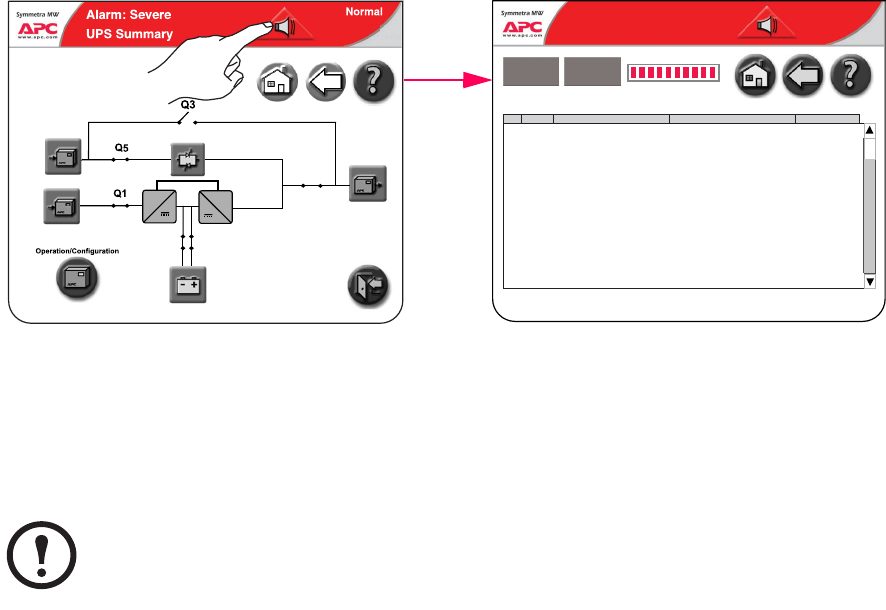
Alarm Types
The color of the top of the screen switches from blue to red when an alarm situation occurs and the
alarm symbol is shown at the top of the screen.
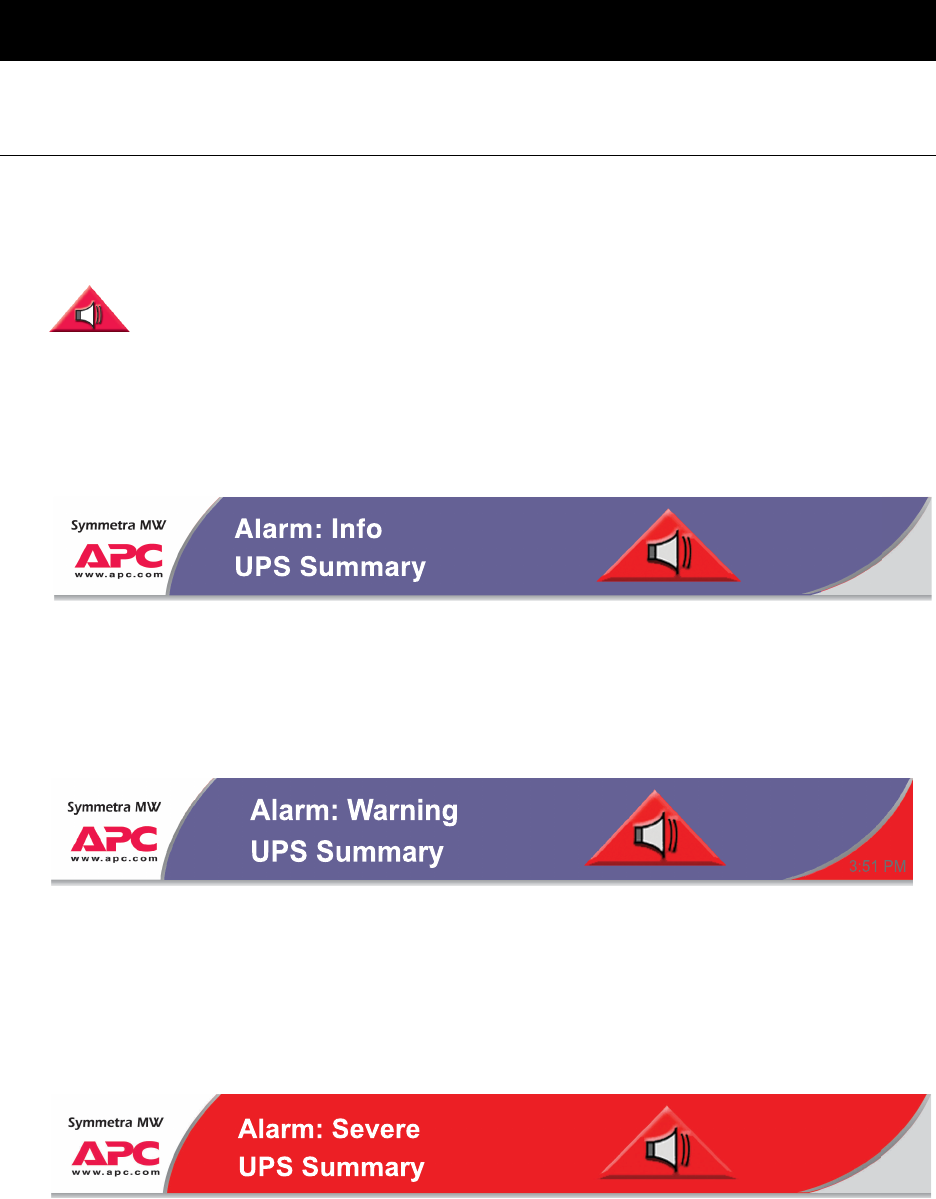
Info
Informational Alarm. No immediate need to take action. Check the cause of the alarm at next
maintenance visit.
Warning
Warning Alarm. Example: The UPS system may have gone into bypass. The load remains supported,
but action must be taken. Call Technical Support. The area in the right side of the top screen
alternates between blue and red.
Severe
Severe Alarm. Take immediate action. Call Technical Support. The red area of the top of the screen
alternates between blue and red.
Alarm button. Pressing the alarm button will take the user to a screen showing all active
alarms and how each alarm should be addressed. The 3 different alarm levels are
described below. Hitting the alarm symbol or any other display button will automatically
silence the alarm.
3:51 PM
Normal
Normal
3:51 PM
Normal
Alarms/Troubleshooting: Alarm Types
42 Symmetra® MW with Internal Bypass Static Switch - User Guide - 990-1756A-001
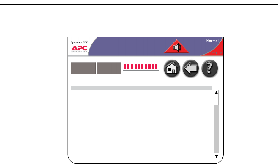
View active alarms
Press the red triangular alarm symbol to view active alarms. Only active alarms will appear on the
screen. Pressing the alarm symbol will also mute audible alarms.
Previous alarms are stored in the Event Log, which contains a detailed record of the system’s last
1024 events.
Note
In the Active Alarms list, the user can see which actions to take to solve the problem.
~~
Q7 Q8
Q2
Mains static switch fan comm. fault
Battery temperature high
Bypass unavailable
Output off
Call APC for service
Check temperature in the battery room
Call APC for service
No output from UPS
06-11-2003 15:45
06-11-2003 15:45
06-11-2003 15:44
06-11-2003 15:44
Warning
Warning
Severe
Severe
Normal
Alarm: Severe
3:51 PM
Active Alarms
Event Log Refresh
SeveritySeverityNo.No. Event DescriptionEvent Description Suggested ActionSuggested Action Date & TimeDate & Time
1
2
3
4

Symmetra® MW with Internal Bypass Static Switch - User Guide - 990-1756A-001 43
APC Symmetra MW Remote Display
The read-only display screens can be accessed via an Internet Browser by typing the IP address of the
Symmetra MW display into the browser’s address field. The remote display feature provides a subset
of the Symmetra MW display screens. Configuration of the Symmetra MW or the display through the
remote display is not supported.
The remote display feature requires Microsoft Internet Explorer 6 SP1 or greater. For best results we
recommend that the Sun JVM version 1.4.2_05 or greater be installed. This is available from Sun’s
website.
The Netscape browser is not supported.
The following screens can be accessed during a remote session:
• UPS Summary screen
• Active alarms screen
• Event log screen
• Input Summary screens
• Output Summary screens
• Battery Summary screens
• Bypass Summary screens
•
Note
Operation/configuration must be done at the UPS.
Note
The event log screen can be accessed through the Operation screen. Only the 50 most
recent events in the Event Log screen can be downloaded.
Note
Network settings must be configured before the remote display feature can be used.
APC Symmetra MW Remote Display:
44 Symmetra® MW with Internal Bypass Static Switch - User Guide - 990-1756A-001
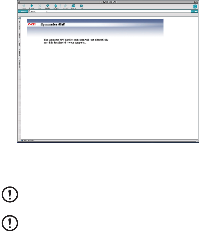
Starting web-based remote session
• Start the web-based remote session by entering the IP address of the APC Symmetra MW UPS
in the web browser address field. After a few seconds, a new window will open and display the
below screen:
• After a few seconds, the UPS display is shown on the screen.
• Use the mouse to touch the buttons to see other screens.
• Close the window or the web browser to end the remote session.
Note
For security reasons, there is a time limit of 30 minutes for a remote session. The
connection will be disconnected after 30 minutes and reconnection is required.
Note
Only one remote session at a time is allowed.
XXX.XXX.XXX.XX

Symmetra® MW with Internal Bypass Static Switch - User Guide - 990-1756A-001 45
Warranty
Factory Warranty
APC warrants that the unit, when properly installed and commissioned by APC or APC
authorized service personnel, shall be free from defects in materials and workmanship for a
period of (1) year from the date of installation or maximum 18 months after manufacturing.
In the event that the unit fails to meet the foregoing warranty, APC shall for a period of one
(1) year repair or replace any defective parts, without charge for on-site labor and travel if
trained & authorized APC personnel has conducted start-up of the unit.
An APC Start-Up Service must be performed/completed by APC or by service personnel
authorized by APC. If not, the on-site factory warranty will be voided and replacement of
defective parts only will be covered. APC shall have no liability and no obligation to repair
the installed unit if non-authorized APC personnel performed the start-up and such start-up
caused the unit to be defective.
APC shall not be liable under the warranty if its testing and examination disclose that the
alleged defect in the product does not exist or was caused by purchaser’s or any third
person’s misuse, negligence, improper installation or testing, unauthorized attempts to repair
or modify, or any other cause beyond the range of the intended use, or by accident, fire,
lightning or other hazard.
There are no warranties, expressed or implied, by operation of law or otherwise, of products
sold, serviced or furnished under this agreement or in connection herewithin. APC disclaims
all implied warranties of merchantability, satisfaction and fitness for a particular purpose.
APC’s express warranties will not be enlarged, diminished, or affected by and no obligation
or liability will arise out of, APC rendering of technical or other advice or service in
connection with the products. The foregoing warranties and remedies are exclusive and in
lieu of all other warranties and remedies. The warranties set forth above, constitute APC’s
sole liability and purchaser’s exclusive remedy for any breach of such warranties. APC’s
warranties apply only to purchaser and are not extended to any third parties.
In no event shall APC, its officers, directors, affiliates or employees be liable for any form of
indirect, special, consequential or punitive damages, arising out of the use, service or
installation, of the products, whether such damages arise in contract or tort, irrespective of
fault, negligence or strict liability or whether APC has been advised in advance of the
possibility of such damages.

46 Symmetra® MW with Internal Bypass Static Switch - User Guide - 990-1756A-001
Life Support Policy
As a general policy, American Power Conversion Corporation and its affiliates and subsidiaries
worldwide (APC) do not recommend the use of any of its products in life support applications where
failure or malfunction of the APC product can be reasonably expected to cause failure of the life
support device or to significantly affect its safety or effectiveness. APC does not recommend the use
of any of its products in direct patient care. APC will not knowingly sell its products for use in such
applications.
Examples of devices considered to be life support devices are neonatal oxygen analysers, nerve
stimulators (whether used for anesthesia, pain relief, or other purposes), autotransfusion devices,
blood pumps, defibrillators, arrhythmia detectors and alarms, pacemakers, hemodialysis systems,
peritoneal dialysis systems, neonatal ventilator incubators, ventilators for both adults and infants,
anesthesia ventilators, infusion pumps, and any other device designated as “critical” by the
U.S.F.D.A.
Symmetra® MW with Internal Bypass Static Switch - User Guide - 990-1756A-001 47
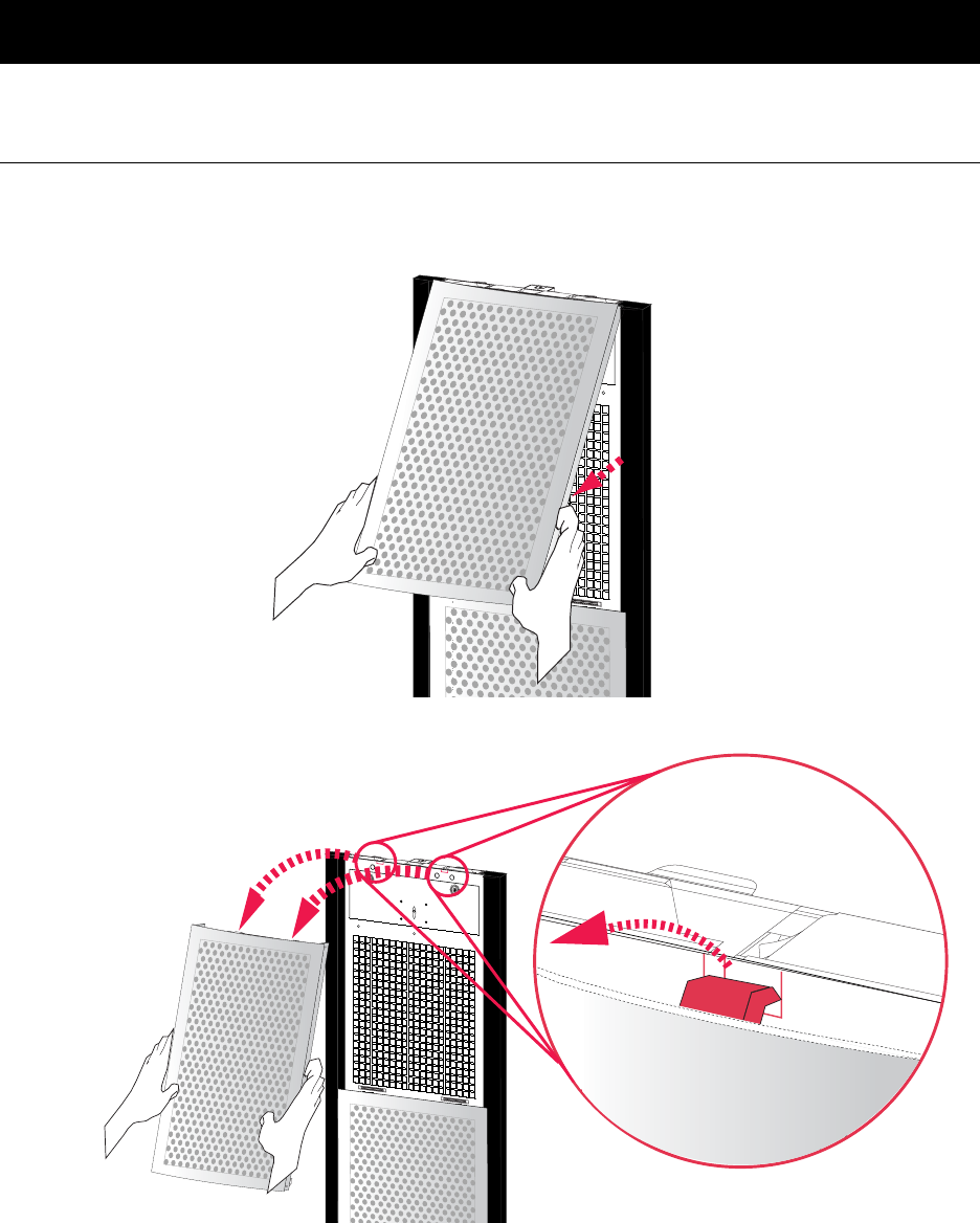
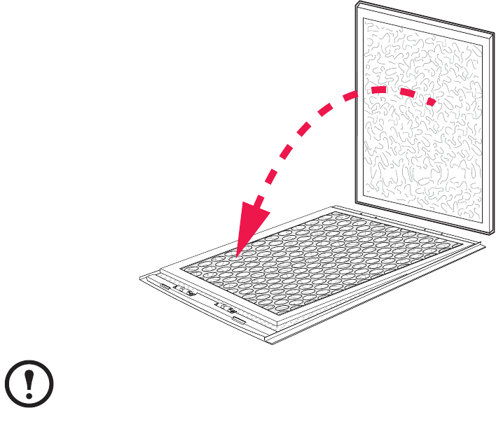
Appendix A
Air Filter Exchange
Check air filters at regular intervals (every 3 months under normal working conditions) for
accumulated dust on the surface facing the finishing panels. Change all filters at the same time.
Pull lower part of top finishing panel free of the UPS.
Lift finishing panel free of the dead front panel and remove.
Follow this procedure to remove the next finishing panel down, until all panels in one row have
been removed. Use the same procedure for the next row of panels until all panels have been
removed from the UPS system.
Appendix A: Air Filter Exchange
48 Symmetra® MW with Internal Bypass Static Switch - User Guide - 990-1756A-001
Remove air filters and install new filters.
Refit finishing panels in reverse order.
Note
Note the orientation of the filter.

*990-1756A-001*
APC Worldwide Customer Support
Customer support for this or any other APC product is available at no charge in any of the following ways:
• Visit the APC Web site to access documents in the APC Knowledge Base and to submit customer
support requests.
–www.apc.com (Corporate Headquarters)
Connect to localized APC Web sites for specific countries, each of which provides customer
support information.
– www.apc.com/support/
Global support searching APC Knowledge Base and using e-support.
• Contact an APC Customer Support center by telephone or e-mail.
– Regional centers:
– Local, country-specific centers: go to www.apc.com/support/contact for contact information.
Contact the APC representative or other distributor from whom you purchased your APC product for
information on how to obtain local customer support.
Direct InfraStruXure Customer Support Line (1)(877)537-0607 (toll free)
APC headquarters U.S., Canada (1)(800)800-4272 (toll free)
Latin America (1)(401)789-5735 (USA)
Europe, Middle East, Africa (353)(91)702000 (Ireland)
Japan (0) 35434-2021
Australia, New Zealand, South Pacific area (61) (2) 9955 9366 (Australia)
Entire contents © 2005 American Power Conversion. All rights reserved. Reproduction in
whole or in part without permission is prohibited. APC, the APC logo, and Symmetra are
trademarks of American Power Conversion Corporation and may be registered in some
jurisdictions. All other trademarks, product names, and corporate names are the property of
their respective owners and are used for informational purposes only.
990-1756A-001 07/2005
