American Security spol s r o AS-ACE 58 kHz ACE System User Manual SW ATT DB N
American Security spol. s r.o. 58 kHz ACE System SW ATT DB N
User Manual - SW-ATT-DB-N

TECHNICAL MANUAL – AM ACE
PAGE 2 of 18
This document was created to provide the intended recipient documentation for technician purposes only. Any other usage of this document is an illegal and unlawful act. This document is a confidential and proprietary document of American Security spol. s r.o. and consists of information that is protected by copyrights or
intellectual property protection of other subjects. All other information, which is not generally known, is intellectual prop erty of American Security spol. s r.o. This document including any and all attachments hereto is intended solely to be used by individuals or entities to which it is addressed. If the reader of this
document is not the intended recipient, or an employee or agent responsible for delivering this document to its intended recipient, you are herewith notified that any dissemination, distribution, copying or retention of this document or the information contained herein is strictly prohibited. If you have received this
document in error, please notify us at info@amersec.com immediately and permanently delete and/or destroy the original and any copy or printout thereof.
TECHNICAL MANUAL – AM ACE
PAGE 3 of 18
This document was created to provide the intended recipient documentation for technician purposes only. Any other usage of this document is an illegal and unlawful act. This document is a confidential and proprietary document of American Security spol. s r.o. and consists of information that is protected by copyrights or
intellectual property protection of other subjects. All other information, which is not generally known, is intellectual prop erty of American Security spol. s r.o. This document including any and all attachments hereto is intended solely to be used by individuals or entities to which it is addressed. If the reader of this
document is not the intended recipient, or an employee or agent responsible for delivering this document to its intended recipient, you are herewith notified that any dissemination, distribution, copying or retention of this document or the information contained herein is strictly prohibited. If you have received this
document in error, please notify us at info@amersec.com immediately and permanently delete and/or destroy the original and any copy or printout thereof.
1.1 BASIC INSTALLATION GUIDE
This section outlines the basic step-by-step processes for installing the AMERSEC® AM ACE system. More details can be found in
further sections of the User Manual.
1.1 Required Materials
1 to 3 pedestals
mains power cable (supplied with system)
stranded 10-core cable for RX pedestals - 3m cables supplied with RX pedestals
USB Hardware Key with telephone cable (RJ14 + RJ12 connectors)
Laptop with Windows XP or later and AM ACE Application installed
#4 hex screwdriver
RJ50 crimping tool (not included) – for RX cables
extra RJ50 plugs (not included) – for RX cables
insulated needle-nose pliars (for changing jumpers if re-tuning is required)
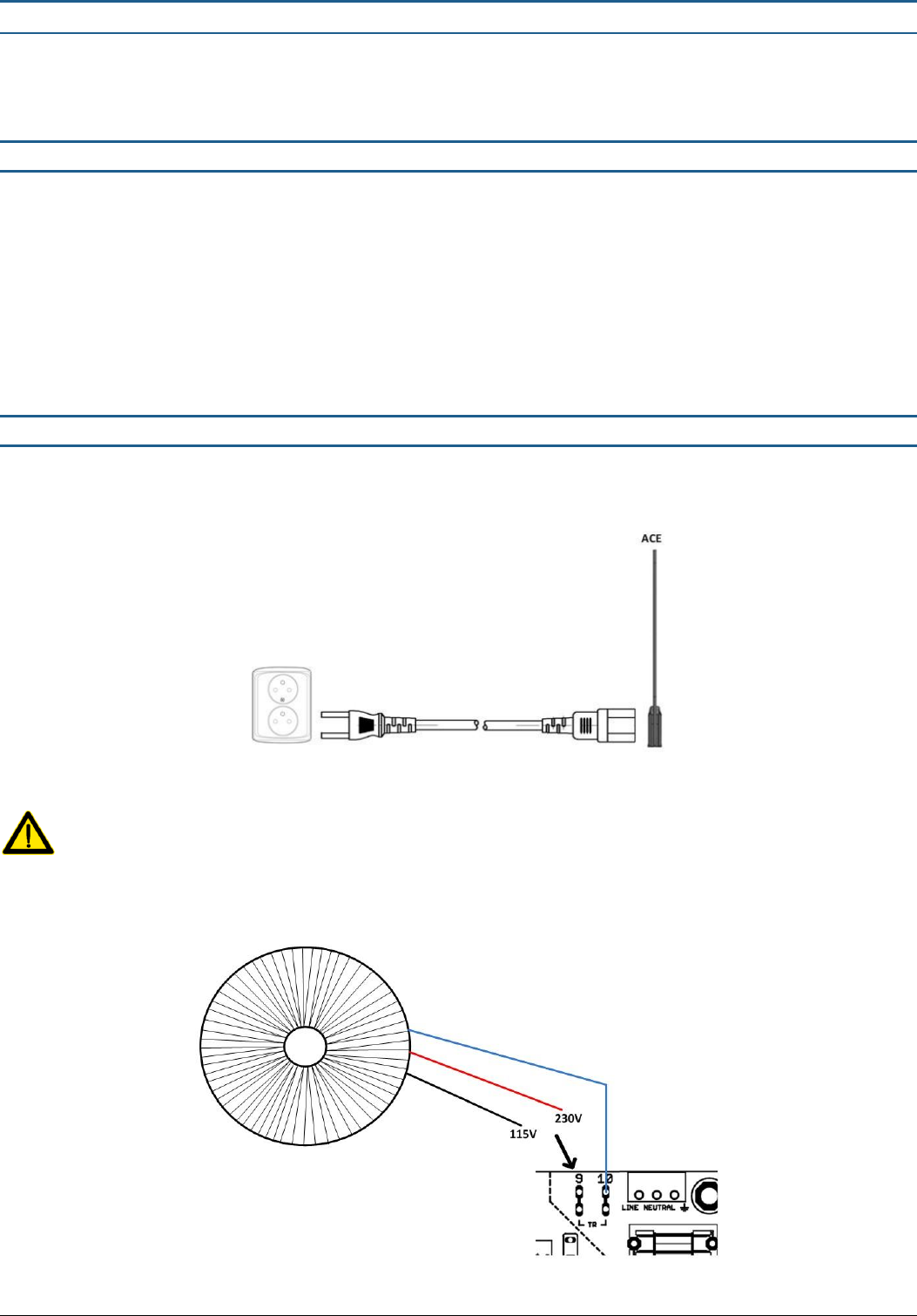
1.2 Powering the ACE System
The ACE system is connected to mains with a standard IEC power cord. If a longer cable is required, a standard extension cable
is recommended.
Figure 1 - ACE Power
Connect the power cord to the ACE system BEFORE you connect to the mains power outlet! DO NOT disconnect the
power cord from the ACE system while the other end is still connected to the mains power outlet!
The toroidal transformer in the ACE system can be wired for 115V or 230V supply inputs. For 230V, connect the RED wire to the
“TR-9” terminal, and for 115V, connect the BLACK wire to the “TR-9” terminal. The BLUE wire will remain connected either way.
Figure 2 - ACE Transformer Wiring
TECHNICAL MANUAL – AM ACE
PAGE 4 of 18
This document was created to provide the intended recipient documentation for technician purposes only. Any other usage of this document is an illegal and unlawful act. This document is a confidential and proprietary document of American Security spol. s r.o. and consists of information that is protected by copyrights or
intellectual property protection of other subjects. All other information, which is not generally known, is intellectual prop erty of American Security spol. s r.o. This document including any and all attachments hereto is intended solely to be used by individuals or entities to which it is addressed. If the reader of this
document is not the intended recipient, or an employee or agent responsible for delivering this document to its intended recipient, you are herewith notified that any dissemination, distribution, copying or retention of this document or the information contained herein is strictly prohibited. If you have received this
document in error, please notify us at info@amersec.com immediately and permanently delete and/or destroy the original and any copy or printout thereof.
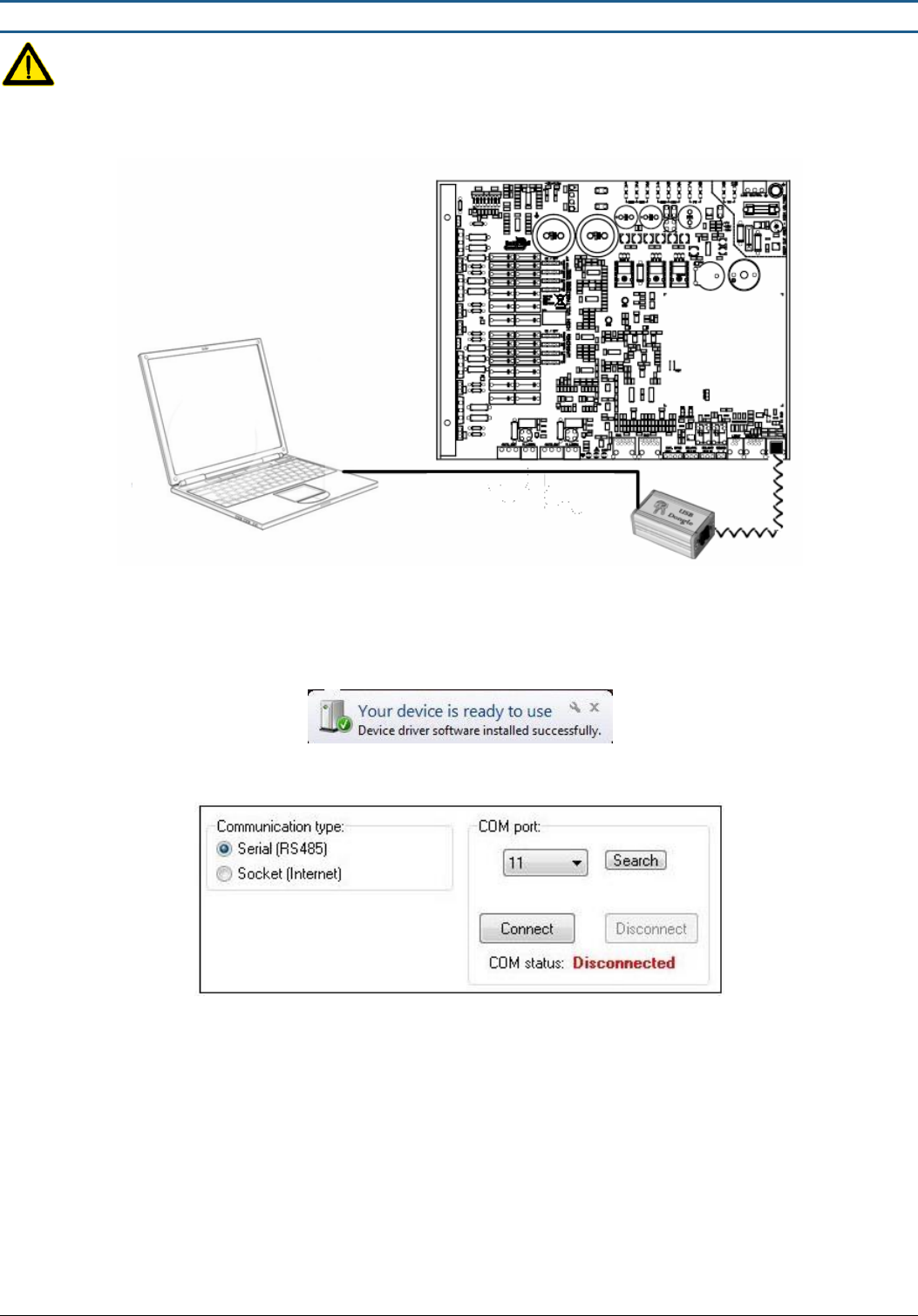
1.3 Connect ACE to PC
Install software and then connect the USB Hardware Key to the PC and the ACE. The white telephone cable which is
connected to the ACE has RJ14 + RJ12 connectors (4/6). Do NOT use the RJ12 + RJ12 cable (4/4).
Figure 3 - ACE to PC Connection with Hardware Key
The Hardware Key is used as a USB converter, and for security. Only 1 key is needed for each technician, it is NOT left
at the installation with the system.
Open the AM ACE Application AFTER the hardware driver is finished installing. Make sure the system is powered ON.
Figure 4 - Hardware Driver Finished
Select “Serial” communication.
Figure 5 - AM Connection
The system will scan the COM ports on the computer. Select the correct COM port and press “Connect”
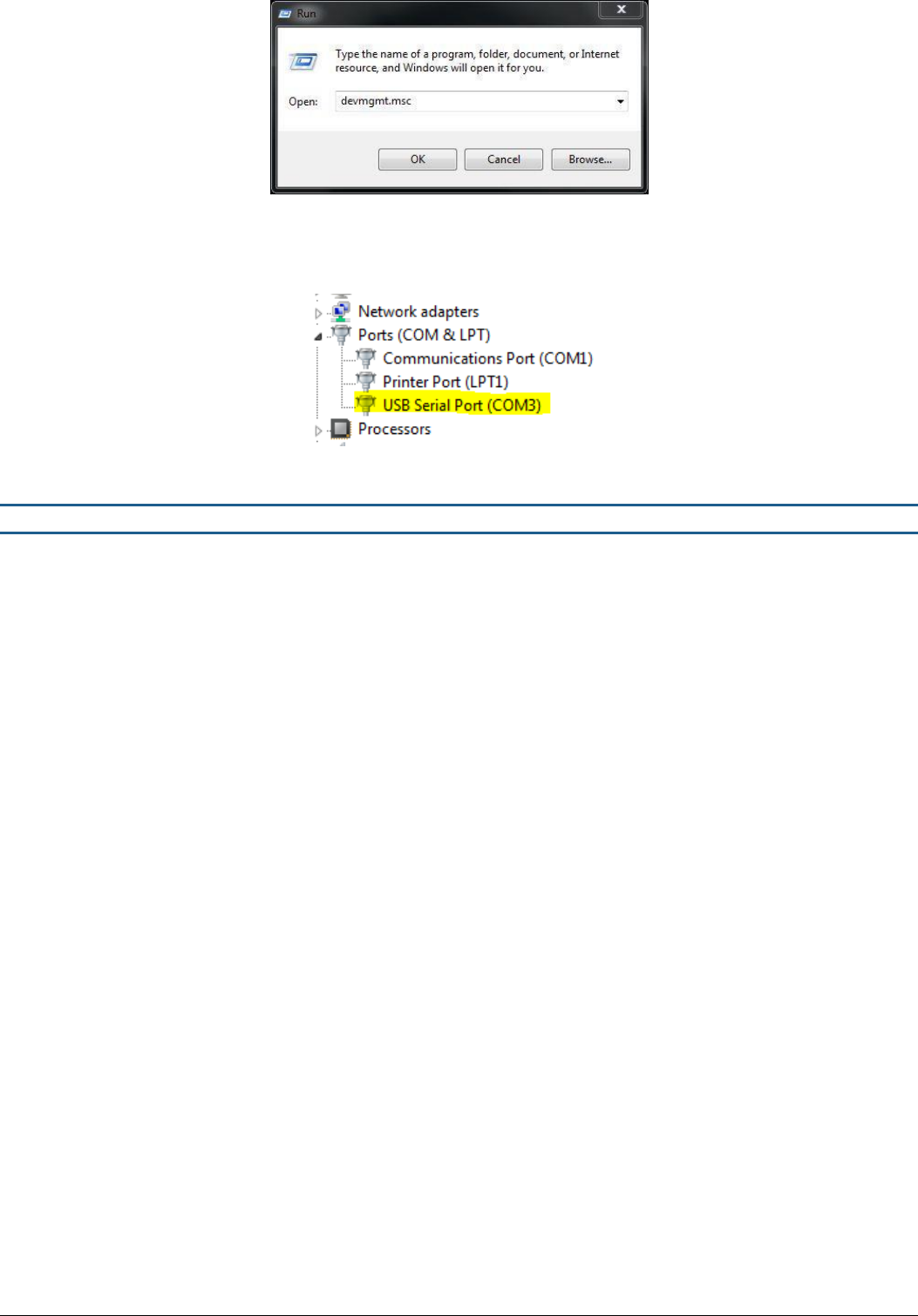
If you are unable to connect to the scanned COM port, you can manually find the correct COM port on your PC
o
Select Start -> Run -> devmgmt.msc -> OK
Requires Windows XP or later
TECHNICAL MANUAL – AM ACE
PAGE 5 of 18
This document was created to provide the intended recipient documentation for technician purposes only. Any other usage of this document is an illegal and unlawful act. This document is a confidential and proprietary document of American Security spol. s r.o. and consists of information that is protected by copyrights or
intellectual property protection of other subjects. All other information, which is not generally known, is intellectual prop erty of American Security spol. s r.o. This document including any and all attachments hereto is intended solely to be used by individuals or entities to which it is addressed. If the reader of this
document is not the intended recipient, or an employee or agent responsible for delivering this document to its intended recipient, you are herewith notified that any dissemination, distribution, copying or retention of this document or the information contained herein is strictly prohibited. If you have received this
document in error, please notify us at info@amersec.com immediately and permanently delete and/or destroy the original and any copy or printout thereof.
Figure 6 - Open Device Manager
o
When Device Manager is open, navigate to Ports (COM & LPT). The Hardware Key will be displayed as “USB
Serial Port (COMX). Select this port in the AM ACE Application and press “Connect”
Figure 7 - Manually Find COM Port
1.4 Software Setup
When you have successfully connected to the AM ACE and have all pedestals connected, you can begin adjustment of the
system. Settings are saved immediately to the system after pressing the appropriate button (Set, Apply, Checkbox, etc.) near
the setting. When entering a number value, press the “ENTER” key to confirm the setting and save it to the system!
On the CONFIG page, select the configuration which matches your pedestal setup. It is important that any additional
RX pedestals are connected to the same port number as is shown in the configuration diagrams!
On the RX page, start with the following settings:
o
Gain = 8
o
Preset Environment = Environment 2
Criteria 1 SET value = 300 for O-loop and 150 for 8-loop
o
Before making any more adjustments, move to the SYNC page
On the SYNC page, synchronize with any surrounding AM systems
o
Your system (blue pulses) should be aligned with any other AM systems (shown as red pulses). The RIGHT
sides of the pulses are most important for alignment!
Go back to the RX page and adjust according to the environment
o
Try to set Gain so that Tag & Bckg levels are green or yellow
o
Criteria 1 – SNR is the signal-to-noise ratio threshold and will have a large effect on sensitivity and false alarm
elimination. Reduce the SET values to increase sensitivity
o
Criterias 2-4 can be adjusted with sliders or turned off completely
o
For extremely hostile environments, use Filter #2. Noise will be reduced, but detection will also decrease
o
For high interference, it is possible to reduce the width of the RX window. This will reduce the interference
and/or make it possible to fit your RX reception in between other pulses.
Go to the TX page and use the following settings:
o
TX Power = 150
It is best to set the TX Power so that the Top and Bottom loops are evenly matched and within the
green or yellow areas.
o
Sweep = Disabled
Go to the ALARMS page and turn on the appropriate alarms for your pedestals
o
Click on the box(es) to turn ON alarms – they will be green when alarm is turned on
TECHNICAL MANUAL – AM ACE
PAGE 6 of 18
This document was created to provide the intended recipient documentation for technician purposes only. Any other usage of this document is an illegal and unlawful act. This document is a confidential and proprietary document of American Security spol. s r.o. and consists of information that is protected by copyrights or
intellectual property protection of other subjects. All other information, which is not generally known, is intellectual prop erty of American Security spol. s r.o. This document including any and all attachments hereto is intended solely to be used by individuals or entities to which it is addressed. If the reader of this
document is not the intended recipient, or an employee or agent responsible for delivering this document to its intended recipient, you are herewith notified that any dissemination, distribution, copying or retention of this document or the information contained herein is strictly prohibited. If you have received this
document in error, please notify us at info@amersec.com immediately and permanently delete and/or destroy the original and any copy or printout thereof.
If the system will be connected to StoreMonitor, go to the RTC page
o
Synchronize the Date/Time with your PC
2.1 PEDESTAL CONFIGURATION & CABLING
This section describes how to set up the ACE pedestals in the correct configuration, including any additional options, and the
cabling which is required.
ACE systems are ideally used for small exits (3 or less pedestals) or for cash desk installations.
2.1 Types of Pedestals
Amersec offers two types of AM ACE pedestals, ACE (also called the Master pedestal) or ACE RX (just called RX)
ACE = Master antenna
ACE RX = Receiver antenna – identical to ACE Master but with RX electronics only. Must be connected to an ACE
Master
Up to 2 RX pedestals can be connected to the ACE.
All possible pedestal configurations are shown in the ACE Application on the Config page
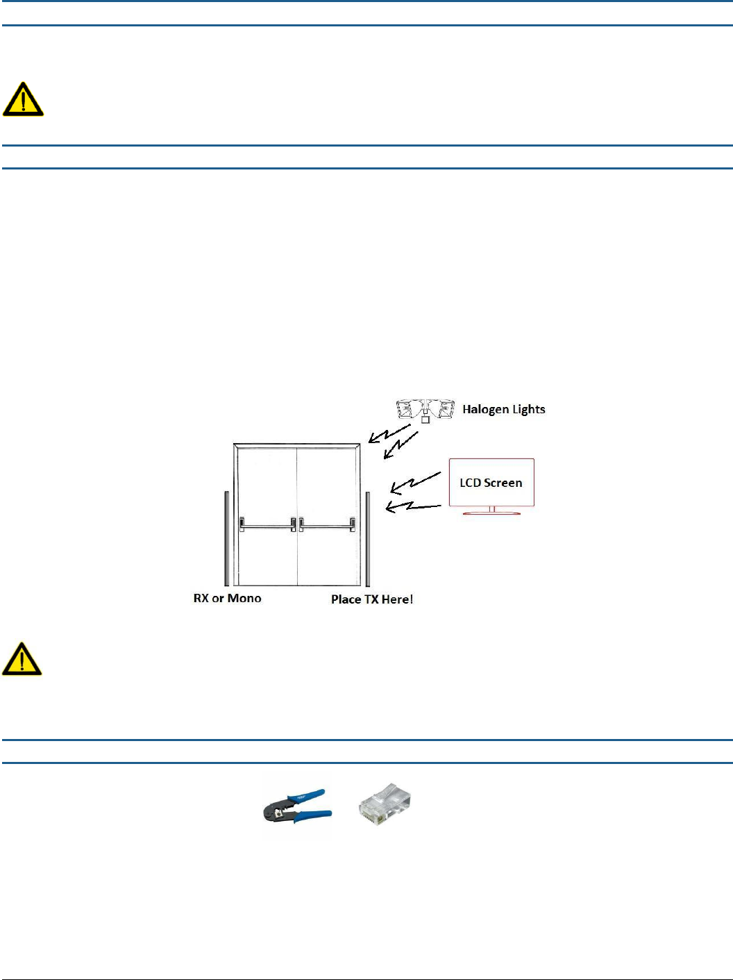
If you have trouble with high interference, try to configure the ACE Master as a TX antenna and place it nearest the
source of interference. The interference will affect Mono and RX pedestals, but it will not affect a Transmitter!
Figure 8 - Interference Configuration
Mono or RX pedestals should be placed at least 2 meters away from LCD screens, depending on the size of the screen!
2.2 Cable Requirements
Required* Tools:
RJ-50 Crimping Tool
RJ-50 plugs
*Only if you need to cut/reconnect any cables
RX cable = RJ50 connectors with STRAIGHT connection (same colors on both ends). 3m of 10-core flex cable is supplied with
each RX pedestal.
TECHNICAL MANUAL – AM ACE
PAGE 7 of 18
This document was created to provide the intended recipient documentation for technician purposes only. Any other usage of this document is an illegal and unlawful act. This document is a confidential and proprietary document of American Security spol. s r.o. and consists of information that is protected by copyrights or
intellectual property protection of other subjects. All other information, which is not generally known, is intellectual prop erty of American Security spol. s r.o. This document including any and all attachments hereto is intended solely to be used by individuals or entities to which it is addressed. If the reader of this
document is not the intended recipient, or an employee or agent responsible for delivering this document to its intended recipient, you are herewith notified that any dissemination, distribution, copying or retention of this document or the information contained herein is strictly prohibited. If you have received this
document in error, please notify us at info@amersec.com immediately and permanently delete and/or destroy the original and any copy or printout thereof.
2.3 One-Pedestal Configuration
Figure 9 – Mono Configuration
ACE Application Config = 0
Additional Options
o
Remote Tuning & StoreMonitor EAS statistics: requires eComm Module with internet connection
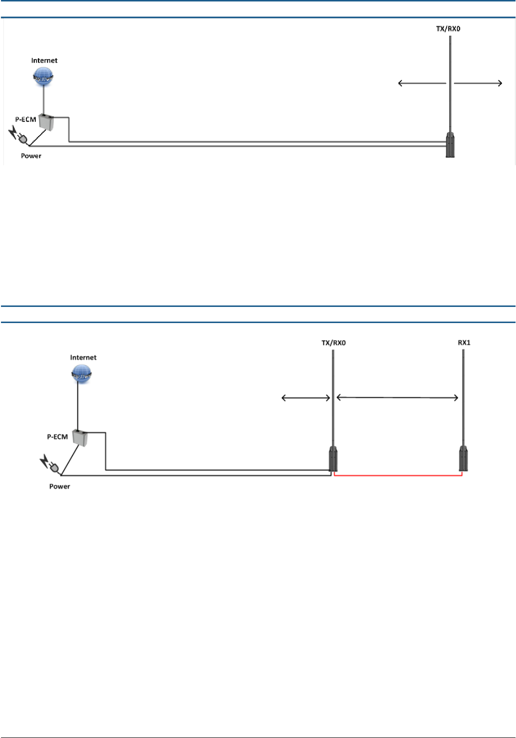
2.4 Two-Pedestal Configuration
Figure 10 – Mono-RX Configuration
ACE Application Config = 1
Additional Options
o
Remote Tuning & StoreMonitor EAS statistics: requires eComm Module with internet connection
It is possible to switch to a TX-RX Configuration (thereby reducing the backfield on the Mono) by setting Config = 2
TECHNICAL MANUAL – AM ACE
PAGE 8 of 18
This document was created to provide the intended recipient documentation for technician purposes only. Any other usage of this document is an illegal and unlawful act. This document is a confidential and proprietary document of American Security spol. s r.o. and consists of information that is protected by copyrights or
intellectual property protection of other subjects. All other information, which is not generally known, is intellectual prop erty of American Security spol. s r.o. This document including any and all attachments hereto is intended solely to be used by individuals or entities to which it is addressed. If the reader of this
document is not the intended recipient, or an employee or agent responsible for delivering this document to its intended recipient, you are herewith notified that any dissemination, distribution, copying or retention of this document or the information contained herein is strictly prohibited. If you have received this
document in error, please notify us at info@amersec.com immediately and permanently delete and/or destroy the original and any copy or printout thereof.
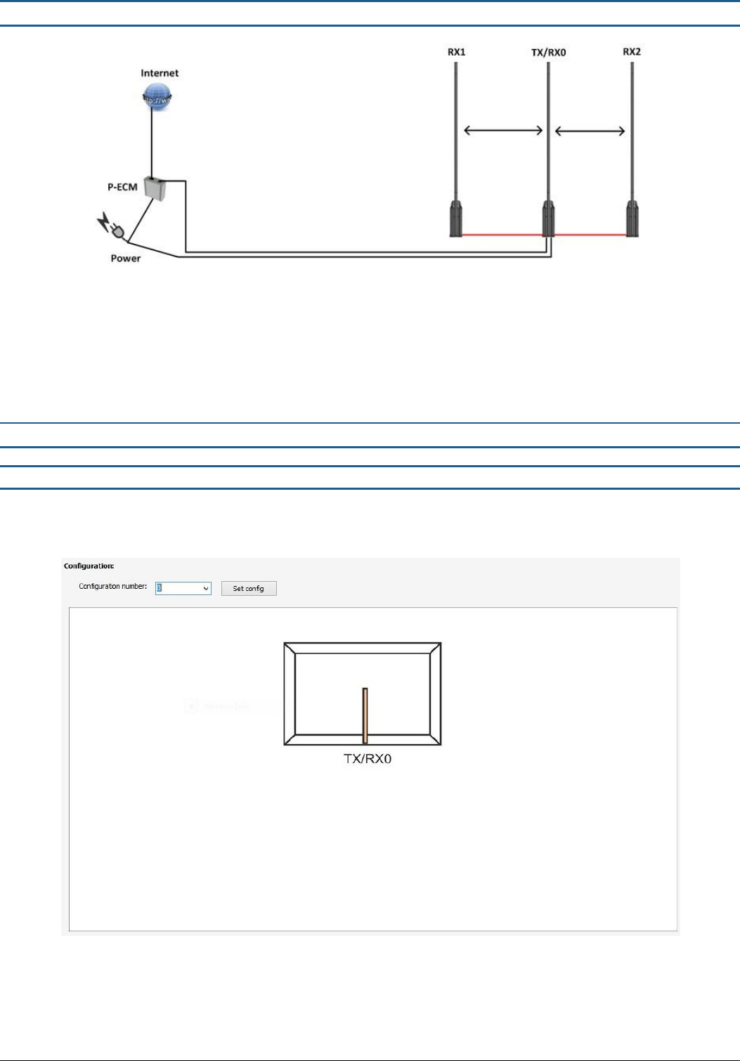
2.5 Three-Pedestal Configuration
Figure 11 - Mono-RX-Mono Configuration
ACE Application Config = 3
Additional Options
o
Remote Tuning & StoreMonitor EAS statistics: requires eComm Module with internet connection
It is possible to switch to an RX-TX-RX Configuration by setting Config = 4. Not recommended
3.1 ACE APPLICATION SOFTWARE SETTINGS
3.1 Configuration
Before making any system settings, select the correct configuration of antennas that you have connected. After selecting the
correct configuration, press Set Config.
Figure 12 - Config 0: Single Pedestal Mono
TECHNICAL MANUAL – AM ACE
PAGE 9 of 18
This document was created to provide the intended recipient documentation for technician purposes only. Any other usage of this document is an illegal and unlawful act. This document is a confidential and proprietary document of American Security spol. s r.o. and consists of information that is protected by copyrights or
intellectual property protection of other subjects. All other information, which is not generally known, is intellectual prop erty of American Security spol. s r.o. This document including any and all attachments hereto is intended solely to be used by individuals or entities to which it is addressed. If the reader of this
document is not the intended recipient, or an employee or agent responsible for delivering this document to its intended recipient, you are herewith notified that any dissemination, distribution, copying or retention of this document or the information contained herein is strictly prohibited. If you have received this
document in error, please notify us at info@amersec.com immediately and permanently delete and/or destroy the original and any copy or printout thereof.
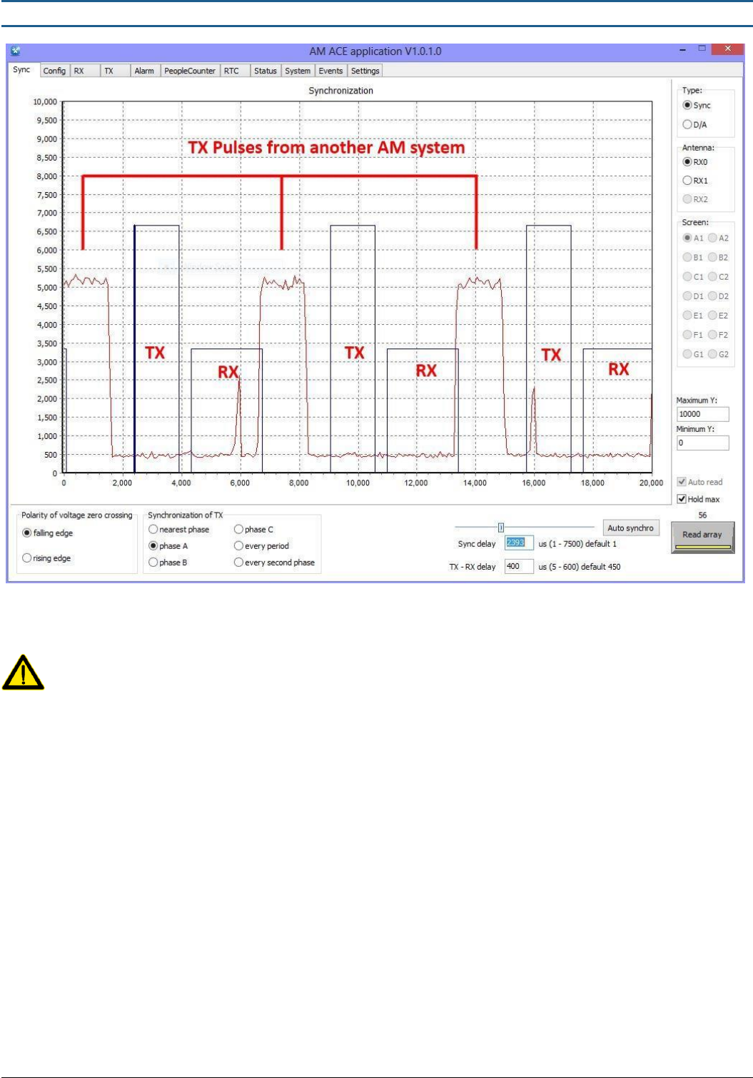
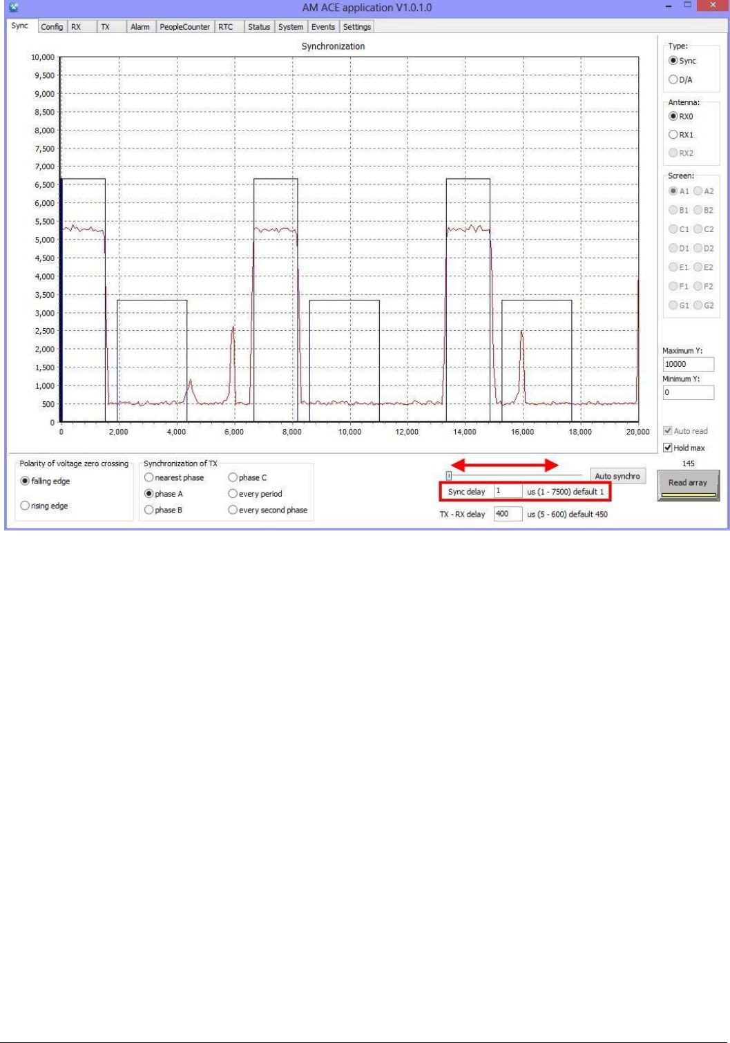
3.2 Sync Page & Synchronization
Figure 13 - Sync Page with Un-Sychronized System
The Sync Page is the most important page in the software. It allows you to easily synchronize with other AM systems,
which is REQUIRED for all AM systems!
The Sync Page also allows you to view all other signals in the environment, which is very helpful for troubleshooting
interference. The BLUE rectangles are a REPRESENTATION of YOUR system. The RED signal is EVERYTHING else in the
environment, including OTHER AM systems.
To synchronize, move the Sync Delay slider so that your TX pulses (blue) are on top of the red pulses from the other AM system.
It is most important to align the RIGHT sides (falling edges) of the pulses. This will introduce a time delay to your system so that
it always pulses at the same time as the other system(s).
Alternatively, you can press the “Auto synchro” button, which will calculate the time delay and move it for you. This is a one-
time calculation – it does not mean that the system will continuously auto synchronize if something changes!
You may also enter the time delay (Sync delay) as a number and then press the “Enter” key to save the value to the system. If
you have MULTIPLE systems in the same store or nearby, it is best to manually enter the SAME number on all systems for
optimal synchronization. That is assuming that the power phasing is the same on all systems.
TECHNICAL MANUAL – AM ACE
PAGE 10 of 18
This document was created to provide the intended recipient documentation for technician purposes only. Any other usage of this document is an illegal and unlawful act. This document is a confidential and proprietary document of American Security spol. s r.o. and consists of information that is protected by copyrights or
intellectual property protection of other subjects. All other information, which is not generally known, is intellectual prop erty of American Security spol. s r.o. This document including any and all attachments hereto is intended solely to be used by individuals or entities to which it is addressed. If the reader of this
document is not the intended recipient, or an employee or agent responsible for delivering this document to its intended recipient, you are herewith notified that any dissemination, distribution, copying or retention of this document or the information contained herein is strictly prohibited. If you have received this
document in error, please notify us at info@amersec.com immediately and permanently delete and/or destroy the original and any copy or printout thereof.
Figure 14 - Properly Synchronized System
Polarity of Voltage Zero Crossing: changes the phase by 180° - same as reversing the Live/Neutral wires on the mains power
Synchronization of TX: selects which phase is used for the synchro calculations
Synchro Settings: synchronize your system by moving the slider, or manually entering a number, or pressing the “Auto synchro”
button (does not continuously synchronize – it is a 1-time calculation)
TX-RX Delay: changes the time delay between the TX pulse and the RX window. This is an important setting for avoiding
resonance and ringdown (leftover TX signal which appears in the RX window as a tag – causes false alarms – the TX signal is
usually from your own system but can also come from nearby systems). To avoid ringdown, either decrease TX Power or
increase TX-RX delay.
Read Array: scan the environment with your RX1 pedestal by selecting “Auto read” and “Hold max” and then pressing the
“Read Array” button
Axis Scale: change the y-axis scale on the graph to zoom in or out depending on the size of the signal
Type: by default, the Sync page will display all signals detected in the environment. For more detailed viewing of signals, select
“D/A”. You can now view different signals for each antenna – basically just more details than what is displayed on the RX page.
TECHNICAL MANUAL – AM ACE
PAGE 11 of 18
This document was created to provide the intended recipient documentation for technician purposes only. Any other usage of this document is an illegal and unlawful act. This document is a confidential and proprietary document of American Security spol. s r.o. and consists of information that is protected by copyrights or
intellectual property protection of other subjects. All other information, which is not generally known, is intellectual prop erty of American Security spol. s r.o. This document including any and all attachments hereto is intended solely to be used by individuals or entities to which it is addressed. If the reader of this
document is not the intended recipient, or an employee or agent responsible for delivering this document to its intended recipient, you are herewith notified that any dissemination, distribution, copying or retention of this document or the information contained herein is strictly prohibited. If you have received this
document in error, please notify us at info@amersec.com immediately and permanently delete and/or destroy the original and any copy or printout thereof.
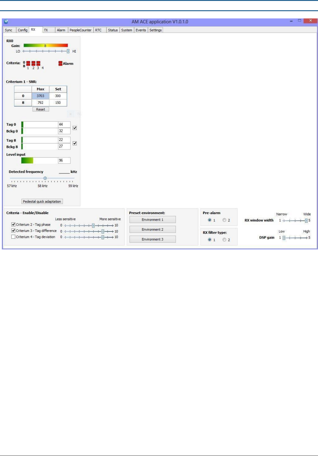
3.3 RX Page
Figure 15 - Receiver Settings
The RX page is used to set the sensitivity of the system. As a starting point, set the GAIN between 6-8 and set the Preset
Environment to Environment 2. Then adjust the GAIN and SNR SET VALUE based on detection and interference levels (false
alarms). The four Criteria can be used to fine-tuning the sensitivity without changing the overall signal level (Gain).
RX windows are displayed according to the selected configuration on the Config page.
Gain: amplitude of the detected signal. Signals from tags as well as interference signals will be increased/decreased by
changing this value.
Criteria LEDs: indicates which criteria are TRUE (green) or FALSE (red). When all criteria are TRUE (green) for either O-loop or 8-
loop, then the system will alarm. It is normal that these will be flashing randomly, which is caused by interference signals. Use
these indications to determine which criteria(s) should be changed for optimum performance.
SNR Setting: criteria 1 setting for signal-to-noise ratio (alarm threshold). Based on detection and false alarm rates, decrease the
SET value for more sensitivity, or increase the SET value for less sensitivity. To see the MAX signal levels in the environment,
press the “Reset” button but do not place a tag near the system. This will display the maximum signal level without tags. The
SET value should be higher than the MAX signal. After entering a number, press the “Enter” key to save it to the system.
Signal Levels: displays the signals in the environment. Do not be too concerned with Level Input – the most important are the
Tag and Background levels. The O-loop signals should always be HIGHER than the 8-loop signals. If not, reverse the wires on
ONE of the loops.
For best performance, the Tag and Bckg levels should be green or yellow. If they are red, try to reduce GAIN and make sure your
system is properly synchronized. The O-loop or 8-loop can be disabled by un-checking the box beside the indicators.
TECHNICAL MANUAL – AM ACE
PAGE 12 of 18
This document was created to provide the intended recipient documentation for technician purposes only. Any other usage of this document is an illegal and unlawful act. This document is a confidential and proprietary document of American Security spol. s r.o. and consists of information that is protected by copyrights or
intellectual property protection of other subjects. All other information, which is not generally known, is intellectual prop erty of American Security spol. s r.o. This document including any and all attachments hereto is intended solely to be used by individuals or entities to which it is addressed. If the reader of this
document is not the intended recipient, or an employee or agent responsible for delivering this document to its intended recipient, you are herewith notified that any dissemination, distribution, copying or retention of this document or the information contained herein is strictly prohibited. If you have received this
document in error, please notify us at info@amersec.com immediately and permanently delete and/or destroy the original and any copy or printout thereof.
Detected Frequency: shows the detected frequency. Really only useful if something is nearby transmitting 58kHz or you have
resonance problems. Tags are detected too quickly for this to be a useful indication for tags/labels.
Pedestal Quick Adaptation: the system will automatically adjust some filter settings based on environment. This button is used
ONLY when testing as after some time the system will reduce sensitivity from multiple testing of the tags. This “resets” the
system back to current environment conditions.
Criteria Settings: fine-tuning of criteria settings for more advanced setting of the system. Can be used to make the system
more/less sensitive without changing the overall signal (Gain). Use the criteria LED indication to help you with these settings.
Some criteria can be disabled by un-checking the box beside the criteria.
Preset Environment: automatically changes the criteria for common presets. Does not change Gain
Pre-Alarm: specifies how many times a tag must be detected before an alarm occurs. Recommended to use 1
RX Filter Type: filter #2 can be used in extremely hostile environments. Extra filters are added which reduces interference
levels. However, detection will be affected so it is recommended to use filter #1 if at all possible
DSP Gain: changes the software digital gain applied to the signal. Use only in the situation that the signal level is so low that the
system is not able to calculate values for detection
RX Window Width: changes the length of time that the system is receiving signals from the environment.
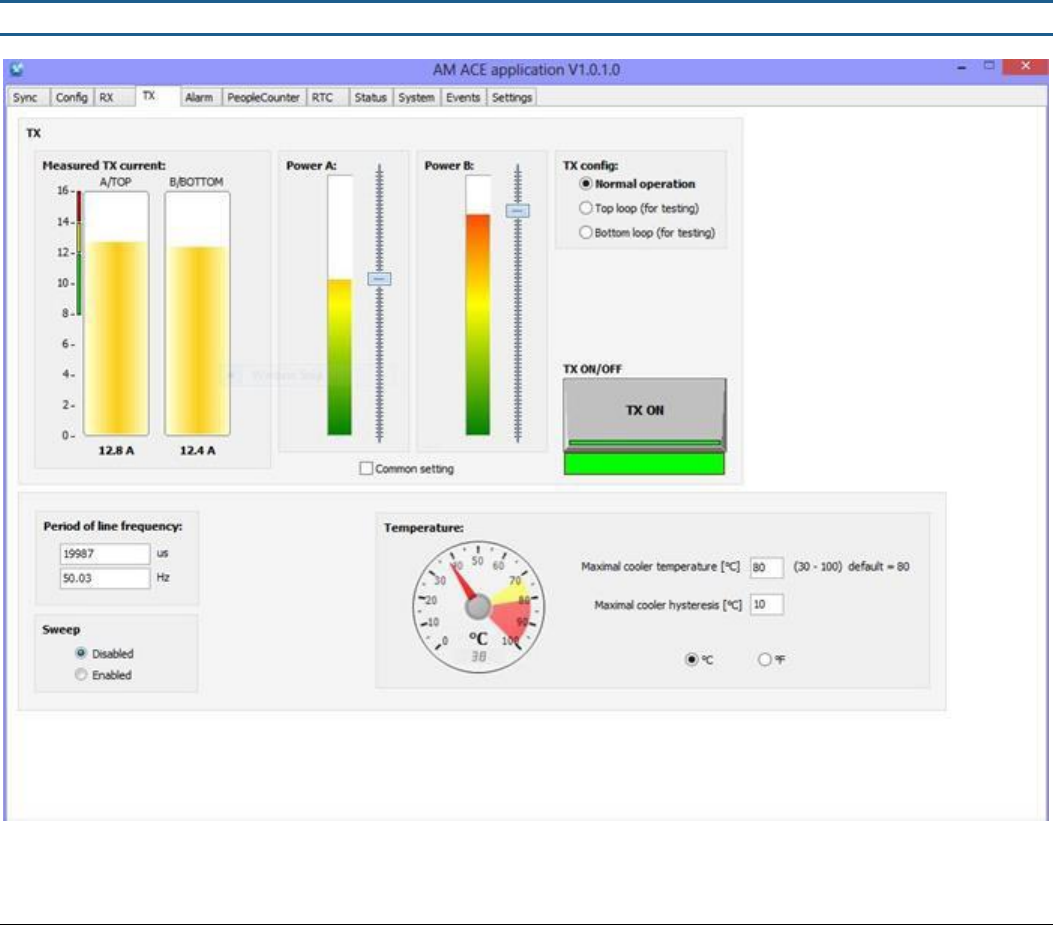
3.4 TX Page
Figure 16 – Transmitter Settings
TECHNICAL MANUAL – AM ACE
PAGE 13 of 18
This document was created to provide the intended recipient documentation for technician purposes only. Any other usage of this document is an illegal and unlawful act. This document is a confidential and proprietary document of American Security spol. s r.o. and consists of information that is protected by copyrights or
intellectual property protection of other subjects. All other information, which is not generally known, is intellectual prop erty of American Security spol. s r.o. This document including any and all attachments hereto is intended solely to be used by individuals or entities to which it is addressed. If the reader of this
document is not the intended recipient, or an employee or agent responsible for delivering this document to its intended recipient, you are herewith notified that any dissemination, distribution, copying or retention of this document or the information contained herein is strictly prohibited. If you have received this
document in error, please notify us at info@amersec.com immediately and permanently delete and/or destroy the original and any copy or printout thereof.
TX Power A & B: recommended setting is so that the Measured Current is within the green or yellow levels. For wide distances
this can be increased, but make sure that ringdown does not occur. If so, then TX power must be decreased or TX-RX delay
(Sync page) increased.
TX Config: used only for tuning of the TX jumpers. The top and bottom loops should transmit a similar MEASURED POWER. If
not, or if Measured Power is low (less than 4A) then the antenna may need to be re-tuned.
Temperature Settings: specifies the temperature at which the transmitters will turn OFF to avoid overheating. When the
system cools down, they will turn back on and resume normal operation.
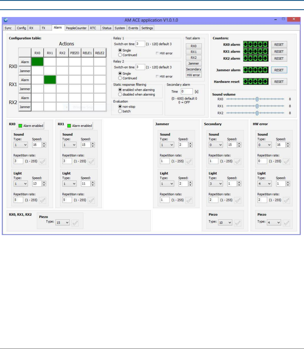
3.5 Alarms Page
Figure 17 - Alarm Settings
Configuration Table: grid for turning on/off alarms. Alarms which are turned on are represented by a green box, while jammer
alarms are represented by a red box. Click on each box to turn it on/off. In the above figure, when the RX0 pedestal detects a
tag, it will turn on the alarm on RX0.
Relay Switch-On Time: specifies the time (in seconds) that the external relays will switch on.
Test Alarms: test each alarm using the current settings
Alarm Settings: each alarm can be configured using the SOUND and LIGHT settings. Common settings are as follows:
1.
Sound (Type, Speed, Rate)
a.
Default = 1,15,3
b.
Modulated = 2,15,3
c.
Beeping = 3,15,1
TECHNICAL MANUAL – AM ACE
PAGE 14 of 18
This document was created to provide the intended recipient documentation for technician purposes only. Any other usage of this document is an illegal and unlawful act. This document is a confidential and proprietary document of American Security spol. s r.o. and consists of information that is protected by copyrights or
intellectual property protection of other subjects. All other information, which is not generally known, is intellectual property of American Security spol. s r.o. This document including any and all attachments hereto is intended solely to be used by individuals or entities to which it is addressed. If the reader of this
document is not the intended recipient, or an employee or agent responsible for delivering this document to its intended recipient, you are herewith notified that any dissemination, distribution, copying or retention of this document or the information contained herein is strictly prohibited. If you have received this
document in error, please notify us at info@amersec.com immediately and permanently delete and/or destroy the original and any copy or printout thereof.
d.
Loudest available = 1,1,3 (make sure Volume trimpot on RX Preamp is at maximum)
2.
Light (Type, Speed, Rate)
a.
Default = 1,11,5
b.
White = 2,1,20
c. Red = 7,1,20
d. Green = 8,1,20
e. Blue = 9,1,20
Static Response Filtering: specifies if the system will filter out resonance signals during an alarm. Recommended is enabled.
Evaluation: recommended is non-stop. Not used at this time.
Secondary Alarm: recommended is OFF. Not used at this time.
Piezo Type: specifies the type of piezo modulation which is on the ACE PCB at the bottom of the pedestal. This does NOT
change the standard alarm sound which is at the top of the pedestal!
4.1 REMOTE SERVICE / ECOMM CONNECTION
If Remote Service or People Counting will be used, it is necessary to connect an eComm Module to the system. The eComm
Module should be pre-configured before going to the installation site. For further information not found below regarding
configuring or connecting the eComm Module, refer to the eComm Module User Manual.
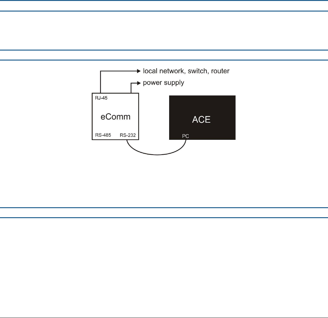
4.1 Connecting an ACE System to an eComm
Figure 18 - eComm Connection to a Single ACE
Connect the ACE to the eComm with the RJ14 + RJ12 (4/6) phone cable. You can leave the address of the system as default
(255). Only the Master ACE pedestal is connected. The RX pedestals will communicate their information to the master through
the RX cable.
4.2 Remote Service Connection
To access your ACE system via Remote Service, connect your Hardware Key to your PC (for security only) and open the
corresponding ACE Application
Select “Internet (eComm)” connection
Enter your StoreMonitor credentials
Browse to the Location where you placed the eComm and press “Connect”
If there are more than 1 devices connected to the eComm, select the desired system. You will now have access to all
settings
TECHNICAL MANUAL – AM ACE
PAGE 15 of 18
This document was created to provide the intended recipient documentation for technician purposes only. Any other usage of this document is an illegal and unlawful act. This document is a confidential and proprietary document of American Security spol. s r.o. and consists of information that is protected by copyrights or
intellectual property protection of other subjects. All other information, which is not generally known, is intellectual property of American Security spol. s r.o. This document including any and all attachments hereto is intended solely to be used by individuals or entities to which it is addressed. If the reader of this
document is not the intended recipient, or an employee or agent responsible for delivering this document to its intended recipient, you are herewith notified that any dissemination, distribution, copying or retention of this document or the information contained herein is strictly prohibited. If you have received this
document in error, please notify us at info@amersec.com immediately and permanently delete and/or destroy the original and any copy or printout thereof.
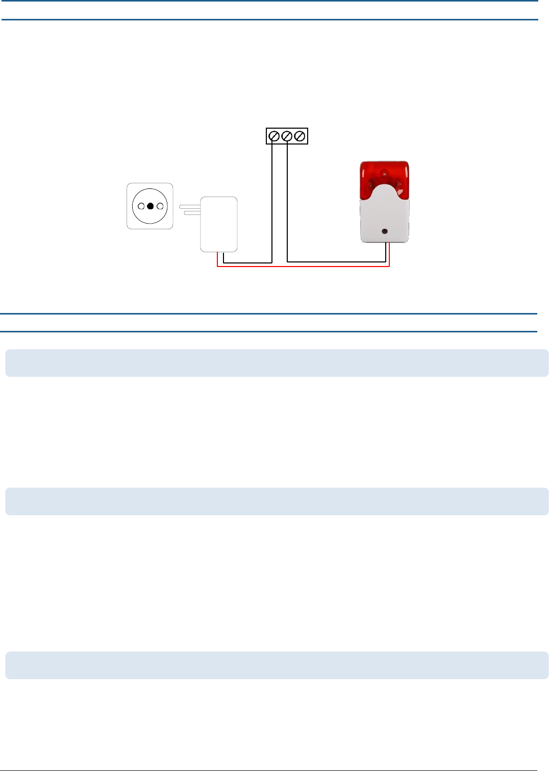
5.1 EXTERNAL RELAYS
There are 2 external relays available on the ACE. They are dry-contact (non-powered) relays. Maximum connected load is 2A.
Each relay has a normally-open (NO) and normally-closed (NC) contact. Any alarm or device can be connected to the relays,
provided they are connected to their own power supply. Common devices triggered by the ACE external relays are sirens, lights,
CCTV, wireless pagers, etc. A common wiring diagram for connecting an external alarm is shown below.
RELAY1
NO C NC
Figure 20 - External Alarm Wiring Diagram
6.1 TROUBLESHOOTING
This indicates an error – the most common is that the system cannot find the “zero-crossing” of the mains frequency. Try
the following steps:
Disconnect all cables and restart the system
Try connecting it to a different mains outlet – a dedicated power source is recommended
Open the pedestal – make sure that all power LEDs are ON and all wires/cables connected well
Try connecting to the software – if possible, reset to default values (Settings page)
Make sure that the Neutral-Earth voltage is no more than 5V. Ideally it should be 0V.
Usually you will have at least a small amount of detection even if the environment is extremely noisy. This is assuming you
have 0% detection. If the alarm counter is counting alarms:
Make sure your alarms are turned on – Alarm page
Make sure the alarm cable is not disconnected from the top of the pedestal
If the alarm counter is NOT counting alarms:
Check your TX Measured Power – if it is very low check TX cables, TX tuning, and make sure loop wires are connected
well
Check Hardware Status LEDs, EEPROM, and RAM in the application
Verify that your Config setting is correct
This can indicate a broken cable – test with a known good cable
Test the antenna on a different RX port – if working the other RX port may be defective
If available, test a different antenna with the same cable and same port – if working the RX Preamp may be defective
12VDC
6.1 THE SYSTEM IS BEEPING CONSTANTLY AFTER BEING POWERED ON
6.2 I HAVE NO DETECTION
6.3 MY RX INDICATES “PEDESTAL ERROR”

TECHNICAL MANUAL – AM ACE
PAGE 16 of 18
This document was created to provide the intended recipient documentation for technician purposes only. Any other usage of this document is an illegal and unlawful act. This document is a confidential and proprietary document of American Security spol. s r.o. and consists of information that is protected by copyrights or
intellectual property protection of other subjects. All other information, which is not generally known, is intellectual property of American Security spol. s r.o. This document including any and all attachments hereto is intended solely to be used by individuals or entities to which it is addressed. If the reader of this
document is not the intended recipient, or an employee or agent responsible for delivering this document to its intended recipient, you are herewith notified that any dissemination, distribution, copying or retention of this document or the information contained herein is strictly prohibited. If you have received this
document in error, please notify us at info@amersec.com immediately and permanently delete and/or destroy the original and any copy or printout thereof.
If the Pedestal Error is intermittent, this can indicate high noise/interference on the RX cable which is affecting the
communication signal. If the problem is bad enough to affect detection of the system, it may be necessary to use a
heavier shielded cable or move the cable to a different position
This is usually caused by either not setting the system sensitive enough, or high interference affecting the system. For
higher sensitivity:
Increase RX Gain
Decrease the SET value for Criteria 1 – SNR. It is usually sufficient to decrease the O loop value
Increase criteria 2-4
Increase TX Power – be careful not to set TX Power too high as the system may start to resonate.
Use RX Filter Type 1
If interference is high:
Decrease RX Gain and try to make the detection acceptable by increasing the sensitivity of the Criteria
Change RX Window Width to minimum
User RX Filter Type 2
Move the antennas closer together
7.1 TECHNICAL SPECIFICATIONS & FEATURES
Features
Excellent detection of AM DR labels and hard tags
All electronics integrated inside of pedestals
Digital Signal Processing (DSP)
Software tuneable
Integrated jamming detection
Choice of RGB alarm light color and behavior
Integrated digital oscilloscope for advanced diagnostics
Advanced, customizeable filters for false-alarm elimination
2 programmable DT contact relays for connecting additional alarm circuits
Technical Specifications
Power Input: 100-120VAC or 220-240VAC @ 50-60Hz
Power Consumption: 150W max
50-60W standard operation
Transformer Output Voltages: 31VAC, 15VAC, 6VAC
Operating Frequency: 58kHz
Sweep Frequency Range: 57.8kHz – 58.2kHz
Transmitted Pulse Width: 1200 - 1600 µsec
Repetition Rate: 75Hz
Fuse T1L250V – 1A Slow, 250V
Operating Temperature: 0-50°C
Pedestal Alarm Audible Level: 90dB
6.4 I HAVE POOR DETECTION
TECHNICAL MANUAL – AM ACE
PAGE 17 of 18
This document was created to provide the intended recipient documentation for technician purposes only. Any other usage of this document is an illegal and unlawful act. This document is a confidential and proprietary document of American Security spol. s r.o. and consists of information that is protected by copyrights or
intellectual property protection of other subjects. All other information, which is not generally known, is intellectual property of American Security spol. s r.o. This document including any and all attachments hereto is intended solely to be used by individuals or entities to which it is addressed. If the reader of this
document is not the intended recipient, or an employee or agent responsible for delivering this document to its intended recipient, you are herewith notified that any dissemination, distribution, copying or retention of this document or the information contained herein is strictly prohibited. If you have received this
document in error, please notify us at info@amersec.com immediately and permanently delete and/or destroy the original and any copy or printout thereof.
8.0 DECLARATION
Operate the system only as described in these operating instructions. Damage to hardware due to improper use will result in
loss of warranty.
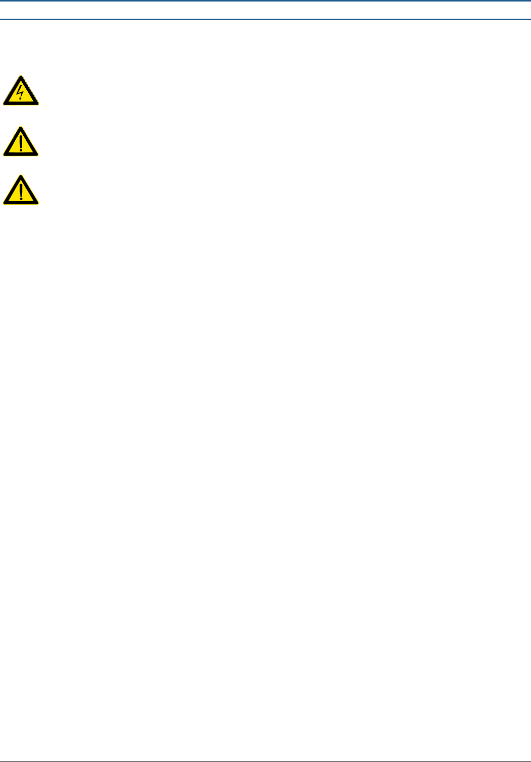
WARNING! Do not open the antenna or touch the electronic boards while system is powered on. RISK OF ELECTRIC
SHOCK!
CAUTION! When connecting or disconnecting cables make sure transmitters are switched off or power to system is
off.
CAUTION! Switch off power when servicing the ACE System hardware
This product conforms with the requirements of the following harmonized standards for electromagnetic compatibility:
-EN 55022: 2006 + A1: 2007;
-EN 61000-3-2: 2006 + A1: 2009+A2: 2009;
-EN 61000-3-3: 2008;
-ETSI EN 300 330-1 V1.7.1: 2010
-ETSI EN 300 330-2 V1.3.1: 2006;
-ETSI EN 301 489-1 V1.8.1: 2008;
-ETSI EN 301 489-3 V1.4.1: 2003.
This equipment has been tested and found to comply with the limits for a Class A digital device, pursuant to part 15 of the FCC
Rules. These limits are designed to provide reasonable protection against harmful interference when the equipment is operated
in a commercial environment. This equipment generates, uses, and can radiate radio frequency energy and, if not installed and
used in accordance with the instruction manual, may cause harmful interference to radio communications. Operation of this
equipment in a residential area is likely to cause harmful interference in which case the user will be required to correct the
interference at his own expense.
The user is cautioned that changes and modifications made to the equipment without approval of the manufacturer could void
the user’s authority to operate this equipment.

TECHNICAL MANUAL – AM ACE
PAGE 18 of 18
This document was created to provide the intended recipient documentation for technician purposes only. Any other usage of this document is an illegal and unlawful act. This document is a confidential and proprietary document of American Security spol. s r.o. and consists of information that is protected by copyrights or
intellectual property protection of other subjects. All other information, which is not generally known, is intellectual property of American Security spol. s r.o. This document including any and all attachments hereto is intended solely to be used by individuals or entities to which it is addressed. If the reader of this
document is not the intended recipient, or an employee or agent responsible for delivering this document to its intended recipient, you are herewith notified that any dissemination, distribution, copying or retention of this document or the information contained herein is strictly prohibited. If you have received this
document in error, please notify us at info@amersec.com immediately and permanently delete and/or destroy the original and any copy or printout thereof.