American Security spol s r o MMS-NCU 20 kHz MMS System User Manual
American Security spol. s r.o. 20 kHz MMS System
UserManual.wiki
>
American Security spol s r o
>
MMS NCU User Manual
User Manual
Navigation menu
Upload a User Manual
Namespaces
Wiki Guide
HTML
PDF
Info
Views
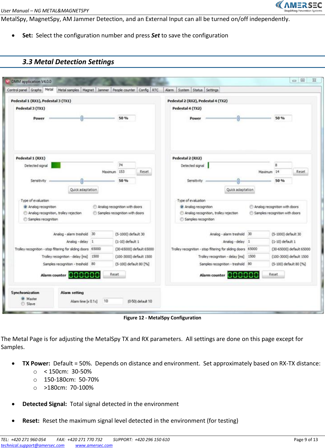
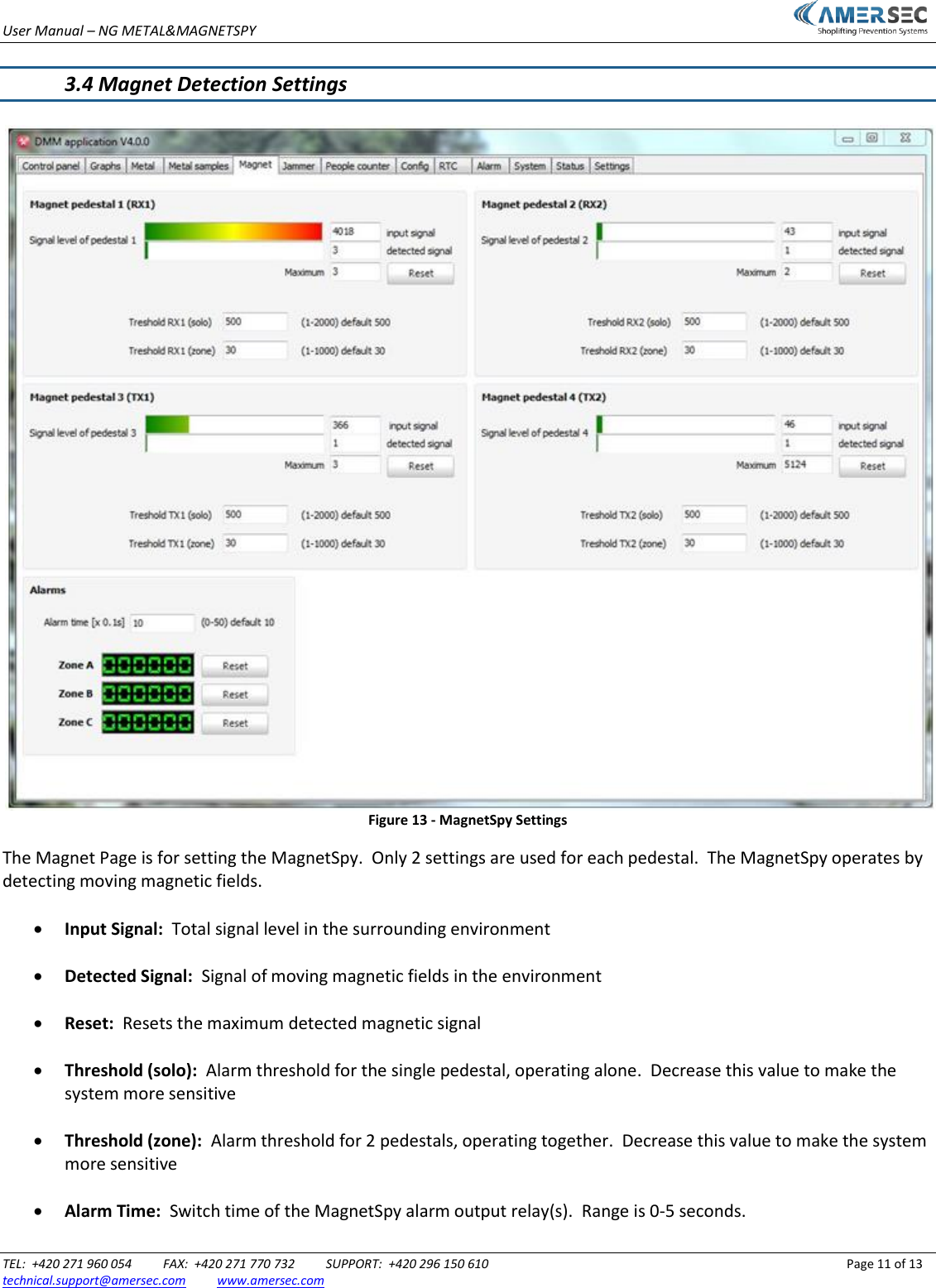
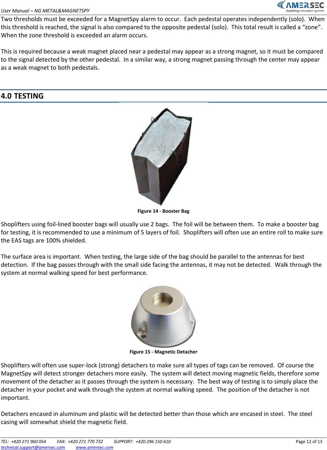
User Manual
Discussion / Help
Navigation