Ameritron 2WUALS606 Amateur Radio Amplifier User Manual Manual
Ameritron Amateur Radio Amplifier Manual
Manual
1
Ameritron ALS-606
600-Watt 160-6 Meter
T-MOSFET AMPLIFIER
The Ameritron ALS-606 is 600-watt nominal output, 160- through 6-meter amateur radio band, solid-state
amplifier. The ALS-606 uses four 50-volt linear RF MOSFETS. These MOSFET’s are specifically designed for
linear power amplifier applications, rather than non-linear or pulse service. They provide lower SSB distortion
when compared to non-linear application solid-state devices in SSB service. Fan speed is regulated by
temperature sensors; assuring conservative cooling with minimal noise.
Nominal driving power is 75-watts for 600-watts output (approximately 9 dB gain) on most bands. The compact
9-1/2” wide by 7” high amplifier package (depth only 14”) fits nearly any station configuration. This attractive
desktop amplifier unit weighs approximately 14 pounds.
An external 50-volt 25-ampere CCS power supply powers the ALS-606. Two different supplies are available,
the ALS-600SPS switching regulated supply and the ALS-600PS unregulated supply. These supplies operate on
all standard residential powerline voltages.
Exhibit VIII Manual ALS-606
HO82WUALS606
Ameritron Engineering
371 Dean Rd. Barnesville, GA 30204
Ph 770-358-3335
Cell 770-596-3514
Email W8JI@W8JI.com

2
Quick Start
Thank you for purchasing this amplifier system.
The ALS606 is a compact 600-watt nominal PEP output amplifier. It uses an external power supply system.
This amplifier covers 160-6 meters. Nominal drive power is 75-watts or less. NOTE: This amplifier excludes
all operation between 25 and 28 MHz.
The ALS606 interfaces with most modern amateur radio transceivers. Supported band data input includes
ICOM compatible analog voltage, Elecraft and Yaesu BCD band data, and Kenwood serial data. With proper
interface cables and data, this amplifier will automatically change bands in step with transceiver band changes.
Automatic band selection using a band data port or band decoded bus requires purchasing an Ameritron
interface cable for your radio.
Carefully unpack this amplifier and power supply. Please inspect everything for physical shipping damage; this
includes cabinets and chassis. Ameritron does not package dented or damaged units. Cabinets and controls can
be broken, bent, or dented with rough handling. If a new unit arrives mechanically damaged, including broken
knobs or switches, it is always from handling somewhere between Ameritron and the end user. In the event of
cabinet damage or broken controls, please contact the dealer immediately. To permit claim processing, retain all
boxes and packing materials.
Installation and Operation
WARNING: Do not block ventilation holes. Do not expose to moisture, water, or external heat.
This power amplifier system consists of two units, a power supply and an amplifier section. The amplifier
section has metering and operator functional controls. Locate the amplifier section at a convenient place with
proper space for airflow, within the operator’s reach and view. The power supply can be placed anywhere
within cable length limits. Do not extend the amplifier power supply dc power cable.
Power Line or Mains Connections
There are two distinctly different power supplies available for the ALS-606. The ALS-600PS is more basic
unregulated choke input supply. The ALS-600SPS is a state-of-the-art regulated switching mode supply. Please
read the appropriate sections below. For non-export use, each supply comes with a standard NEMA 5-15P two-
blade 120V 15A plug with round safety-ground pin.
Overall amplifier operation remains similar with either supply; except the linear supply has a RTTY and
Normal voltage switch. The RTTY position allows higher amplifier efficiency at reduced power. See the power
supply details included with the particular power supply for details specific to each supply. This includes
operation on various line voltages, power supply operation, fuse selection, location, and power supply trouble
shooting.
Non-export versions of Ameritron ALS-600 series power supplies are wired and fused for 120Vac USA power
mains, but all are modifiable to other standard power mains voltages.
3
ALS-600SPS
1.) The USA standard version ALS-600SPS is supplied wired for 95-135 Vac, 50-400 Hz, 15-ampere or
larger electrical service. Reconfiguring internal jumpers on the power supply board will allow 185-260
volt operation.
2.) The ALS-600SPS is internally regulated. Beyond 120 or 240V concerns, the ALS-600SPS does not
require voltage tap changes. There should be very little change in HV1 (PA voltage) with amplifier
power and line voltage. Less than 3 volts change from the 50Vdc nominal voltage is acceptable
3.) Do not operate with line voltage below 95 or above 135 volts (185-260 volts when wired for “240
volts”).
4.) Unless power mains fall below 100 volts, the ALS600SPS switching supply provides the same
performance on 120-volts as on 240-volts. The only function reasons for 240-volt power mains are light
dimming and unintentional line breaker opening. If outlet wiring is already loaded heavily, or if house
wiring is sized too small for the distance to the mains supply, you may have to use a dedicated 120-V
amplifier line, or rewire the supply and use 240-volt mains
5.) With 120Vac mains at 600-watt nominal RF output, current draw is approximately 12 amperes on steady
carrier. Peak line current is typically much less than 8 amperes at 600 watts PEP on SSB voice
6.) The ALS-600SPS can be located anywhere, within reach of interfacing cables, convenient to your
operating setup. The location must be dry, airflow must not be restricted, and outside temperature must
not be over 120F (49C). You must not extend or shorten the amplifier to power supply cable
7.) Exceeding safe power supply load current forces the switch mode supply into shutdown. Restore
operation by turning the main power switch off for a brief time. If the power supply detects a permanent
overload or the supply has failed, the supply will not reset
ALS-600PS
The ALS600PS uses a standard transformer with choke input filter system. It weighs significantly more than
the ALS-600SPS, and is not voltage regulated.
1.) The ALS600PS requires a 100-130 Vac, 50-60 Hz, 15-ampere or larger mains supply. This supply is
reconfigurable for 210-250 volts by moving internal jumpers. The line cord uses a standard USA NEMA
5-15P two-wire male plug with safety ground
2.) This supply is unregulated. Voltage range includes all typical residential power line voltages, but the
internal buck-boost winding must be reconfigured if output voltage is more than 58 volts no load.
Operation with no load voltages over 58 volts can compromise FET reliability
3.) With 120Vac mains, current draw with steady 600-watt carrier is typically around 12 amperes. Line
current is typically less than 8 amperes at 600 watts PEP SSB voice.
4.) The ALS600PS normally provides the same performance at 120-volts as at 240-volts, unless the power
mains have excessive voltage drop. If you experience light dimming or line breaker opening, move the
supply to a dedicated 120-V line, or reconfigure the supply for, and use, 240-volts
5.) This supply does not have overload protection, other than standard fuses

4
Radio and Antenna Connections
WARNING: Forcing connector engagement can result in permanent connector damage. Solder on the
outside of center pins or bent pins are primary causes of female connector damage. External solder or bent
center pins can permanently damage the female.
Do not use Line Isolators on amplifier RF cables. The chassis of the amplifier should be at the same RF
potential as all other desk equipment. Shield isolators allow equipment to float to different RF chassis
potentials. Different chassis potentials are exactly what we do not want, and isolators on desk coaxial cables
encourage differing enclosure RF voltages. It is better to cure RF problems outside the operating position.
1.) RF connections are through standard UHF female connectors. Use 50-ohm coaxial cables with quality,
properly soldered, UHF male (PL259) connectors. The output cable must safely handle at least 600
watts
2.) Examine the RF connectors. Female SO-239 UHF connectors have notches on the outer threaded-area
edge. PL259 UHF males have protruding tabs on the metal outside the center-pin insulator. These tabs
and notches prevent unwanted connector rotation. The male tab or tabs must align and fit into female
notches. This interlocking prevents connector rotation. It is best achieved by slightly wiggling or
rotating the cable while hand-tightening the male’s shell to seat the male tab in the female notch.
3.) With a firm handgrip, while making sure the PL259 male connector tab interlocks with the amplifier’s
SO239 chassis connector notch, gradually tighten RF connectors. Do not use excessive force on
connectors. Check for proper tightness and seating by wiggling and flexing the cable and watching for
any male connector movement on the female. Properly seated, connectors will be solidly locked without
use of pliers or tools
4.) ALC and Relay (keying or TR line) connectors are standard phono females. Phono males from external
cables should push directly in with a snug, but not overly tight, fit
5.) The Relay line operates with low voltage (<12V) and low current (<20 mA). Transmit is enabled by
pulling the Relay line to ground with a relay contact or transistor. Read your radio manual. Unless you
have a very unusual radio, your radio should directly key this amplifier. Avoid using external interfaces
with relays. Amplifier relay switching time is approximately 10-12 mS
6.) The remote and radio band data connectors are specialized connections. They are for use with Ameritron
supplied cables only

5
Operation
Before attempting operation:
1.) This amplifier is optimized for 50-ohm loads. Be sure your antenna system 50-ohm SWR is as
low as possible. As SWR increases from 1:1, either heat or distortion will increase
2.) Be sure your antenna system, including any switches, baluns, matching circuits, or lighting
protection devices, are in good condition and will safely handle high power
3.) Connectors, cables, and antennas must not have loose connections or insulation failure issues
4.) Your exciter must be adjustable to significantly less than 100-watts output. Start at 50 watts
maximum drive power and increase or decrease drive to reach desired power. Do not exceed 25
amperes or 600 watts, and do not drive into non-linearity on SSB. A trapezoid scope pattern is
recommended for drive adjustment. Overdriving results in an excessively wide signal, and
overdriving can damage the amplifier
5.) Power mains should be reasonably stable and match power supply voltage wiring
6.) The low pass filters cut off just above the traditional primary amateur bands. A primary band’s
filter is used on the next lower WARC band. For example, the 20-meter low pass filter is used
on 30 meters. Some radios do not supply enough band data to know the exact band. With these
radios, amplifier band data displays the next higher primary band above the radio’s WARC
band. If you are using such a radio, do not be alarmed if 15 meters illuminates when the radio is
on 17 meters. This is still the correct filter
7.) The amplifier will automatically attempt to reduce power if it appears thermal limits will be
reached
8.) The amplifier will shut off with an incorrect band selection, high antenna SWR (even for an
instant), if safe thermal limits are reached, or with catastrophic failures.
9.) The ALS-606 reads peak envelope power on forward and reflected RF power scales

6
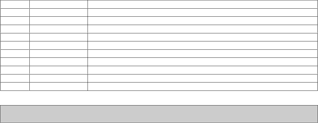
Alerts
This amplifier has front panel alert codes using the SWR, PA, TX, warning LED’s and bandswitch band
indicators. When a fault code appears, the amplifier is disabled. When an operating problem is corrected,
operation is restored and alerts canceled by moving the front panel Standby/Operate switch to Standby. The
following table applies to faults:
Warning light
Steady
Warning light
Flash
Fault
Cause or Cure
SWR
TX
Antenna Reflected Power
High antenna SWR or intermittent antenna
or feedline connection
SWR, PA
Band
Wrong filter
Filter input SWR
Exciter or amplifier on incompatible band,
filter failure
PA, TX
PA FET too hot
Excessive power for duty cycle or SWR,
lack of proper airflow
10M, PA, TX
Illegal 11 meter
Excessive 27 MHz signal level
REM, PA
No data or bad band data when
on remote
Defective or improper remote cable, or bad
radio band data information
With proper station installation, and with low antenna SWR, amplifier operation is straightforward:
1.) Set the bandswitch to the desired band. This happens automatically in the REM position with a suitable
radio interface cable. Set ALC full clockwise. Turn the amplifier power switch ON, but leave the
amplifier in STANDBY
2.) Set the exciter or transceiver to 50 watts carrier power. This power should show on the amplifier’s
FORWARD POWER meter. REFLECTED power should be very low
3.) Move the amplifier standby-operate switch to OPERATE
4.) Transmit while watching the Forward Power reading, quickly adjust exciter power for less than 25 amps
Id current, or less than 600-watts power output
5.) For high duty cycle modes and long transmissions, or if linearity is a problem, reduce power. The
amplifier has overload protection circuits, and will also attempt to reduce power if the FET’s approach
safe limits, but it is best to not rely on protection
6.) Adjust ALC to limit either forward power or amplifier PA current to a desired value at or below
maximum ratings, counterclockwise reduces power and current. The ALC light should just flicker if
ALC is limiting power properly. If the ALC light is on almost continuously, reduce the transmitter’s
power output setting
7
Typical Wiring
8
Table of Contents
TABLE OF CONTENTS .......................................................................................................................6
AMPLIFIER FEATURES ......................................................................................................................7
POWER SUPPLY............................................................................................................................... 10
Power Line Requirements ...................................................................................................................................................................11
Power Supply Features........................................................................................................................................................................10
Power Supply Location.......................................................................................................................................................................11
GENERAL INFORMATION ................................................................................................................11
Amplifier.............................................................................................................................................................................................12
INSTALLATION..................................................................................................................................12
INTERCONNECTION WIRING...........................................................................................................15
AMPLIFIER REAR PANEL ................................................................................................................17
FRONT PANEL ..................................................................................................................................19
OPERATION.......................................................................................................................................15
MARS OR CAP OPERATION ............................................................................................................15
INITIAL OPERATION .........................................................................................................................20
CIRCUIT BOARDS.............................................................................................................................22
TECHNICAL INFORMATION.............................................................................................................22
9
Amplifier Features
This amplifier provides the following standard features:
160- through 6-meter operation, full-power on six meters
Four conservative linear-service rated 50-volt MOSFET transistors
New push-pull stripline PA layout with exceptional VHF performance
Energy-efficient solid-state design greatly reduces heat, <100-watts power line draw on receive
Exceptional harmonic suppression
Operational in a few seconds, no long filament warm-up time
Clean layout with easy-to-service modular construction
Quiet variable-speed forced-air cooling system
Power module current and voltage meters with LED illumination
Accurate PEP Forward and PEP Reflected output power metering
Reflected power protection
Thermal overload protection
Bandswitch error protection
Easy to understand front panel LED indicators for rapid fault-error diagnosis
Standard negative-going ALC output with front panel adjustment
ALC metering and ALC LED indicator
Fully-regulated external switch mode power supply, or linear unregulated supply
Compact size 14” deep x 7”high x 9.5” wide
Weight amplifier section 15 pounds
10
Power Supply
ALS-600PS
Power Supply Features
Normal operating range is from 100 volts up to 130 volts 50/60Hz (12-amperes typical full carrier
power) or between 200 and 250 volts, 50/60Hz (6 amperes typical at full carrier power)
A unique "buck-boost" winding allows compensation for up to six different power line voltages centered
on 115 and 230 volts. This versatile Ameritron feature maintains optimum voltages on the
amplifier components for maximum performance and life
The ALS-600PS standard power supply uses an input choke to provide low power factor loading on
power lines. This reduces the peak currents drawn from the line and improves the voltage regulation of
the supply. This makes the ALS-600PS generator and inverter friendly within the acceptable powerline
frequency range of 50 to 60 Hz
Step-start to limit stress on power supply components
An illuminated cross-needle meter monitors 50V line output voltage and current
Weight 33 lbs.
ALS-600SPS
Power Supply Features
Efficient operation from 100-130 volts ac (12 amperes typical at full output power) or
Low standby and receive power drain, typically less than 100-watts
Generator and inverter friendly with acceptable powerline frequency range 40 to 400 Hz
Fully-regulated current-limited outputs
Excellent voltage regulation
Exceptional filtering and RFI suppression eliminates receiver birdies common to most SMPS
Light weight 13 lbs.
Inrush protection
An illuminated cross-needle meter monitors 50V line output voltage and current.
The ALS-606 external power supplies contain 14-volt positive and negative supplies, as well as a 50-volt 25-
ampere continuous (30-ampere peak) main supplies. The ALS-606 PA (power amplifier) module operates from
50-volts, giving a total dc supply rating of 1250 watts average power and 1500 watts peak dc power. The 12-
volt supplies are for illumination, bias, and control functions.
Power supply to amplifier interconnections are through a heavy-duty cable using reliable Cinch Jones
connectors.
11
Power Line Requirements
This amplifier ships wired for a nominal mains voltage of 120 Vac with either supply. Maximum powerline
current at full power output is 12 amperes at 120 volts. 250-volt rated 15-ampere fuses protect the power line.
Always use 125V or 250V line fuses. The linear supply requires changing taps for different line voltages. The
switching power supply is voltage regulated, current limited, and automatically adapts to any mains voltage
between ~95 Vac and 135 Vac. The ALS-600SPS switching supply does not require adjustments or voltage tap
changes.
Note: 240-volt power mains operation is possible. This will not normally increase power. Because average
power is very low, SSB operation is generally unaffected by 120- or 240-volt operation. 240-V fuse size is 8-
amperes maximum, fast blow only. The fuse must have a voltage rating of 250VAC
Power Supply Location
Locate the power supply in a ventilated area convenient to the amplifier location. Avoid placing the power
supply next to sensitive equipment, such as audio processors, transceivers, or microphones. For safety, ground
the wing nut stud on the supply rear to the station ground buss. The station ground buss should comply with
National Electrical Codes. NEC safety and fire protection codes mandate direct bonding of station grounds to
the home powerline entrance ground. Station ground rods not directly bonded with a low impedance connection
to utility entrance grounds will increase equipment or property damage, and increase personal risk,
significantly.
General Information
Alert Codes
This amplifier has front panel alert codes using the SWR, PA, TX, warning LED’s and bandswitch band
indicators. When a fault code appears, the amplifier is disabled. When an operating problem is corrected,
operation is restored and alerts canceled by moving the front panel Standby/Operate switch to Standby. The
following table applies to faults:
Warning light
Steady
Warning light
Flash
Fault
Cause or Cure
SWR
TX
Antenna Reflected Power
High antenna SWR or intermittent antenna
or feedline connection
SWR, PA
Band
Wrong filter
Filter input SWR
Exciter or amplifier on incompatible band,
filter failure
PA, TX
PA FET too hot
Excessive power for duty cycle or SWR,
lack of proper airflow
10M, PA, TX
Illegal 11 meter
Excessive 27 MHz signal level
REM, PA
No data or bad band data when
on remote
Defective or improper remote cable, or bad
radio band data information

12
Amplifier Overview
The Ameritron ALS-606 is a solid-state, 600-watt nominal RF output power, 1.8-54 MHz amplifier. The ALS-
606 meets or exceeds all FCC requirements governing amateur radio external power amplifiers.
The ALS-606 uses four low-distortion MRF-150 (or equivalent) SSB RF power transistors in push-pull parallel.
Ameritron recommends running 600 watts or less peak power for maximum linearity and component life. It is
always a good idea to use an oscilloscope to verify proper linear SSB operation.
Protection circuitry reduces power as transistors approach conservative thermal limits, and disable the amplifier
before exceeding safe transistor operating temperature limits. (See warning table.) A fan speed-control system
monitors heatsink temperature.
Room temperature amplifier bias is nominally 250 mA per FET, or approximately 1-ampere total. Amplifier
supply voltage is nominally 50-Vdc. Maximum allowable voltage is 58 volts.
Harmonic suppression comes from push-pull operation of linear devices, followed by 5-pole low-pass filters.
This amplifier uses modern multi-layer high voltage chip capacitors where applicable. Chip capacitors, due to
low internal inductance and higher Q, offer significantly improved harmonic suppression. Harmonic and
spurious suppression is excellent; external low-pass filters have minimal effect on TVI. The most likely cause
of any RFI or TVI will be fundamental overload from inadequate consumer device RFI immunity.
Relay switching time is approximately ten milliseconds. Radio adjustable TX delay should be set to ten mS.
The T/R “Relay” control jack is well within the range of almost any transceiver or radio. The “Relay”jack has
an open circuit voltage of approximately 12 volts, and closed circuit current less than 15 mA. Virtually any
modern amateur radio will directly key this amplifier.
This amplifier includes full metering using large easy-to-read conventional cross-needle panel meters. The
meters read all critical parameters, including Forward and Reflected peak envelope RF power.
Installation
Please look your amplifier and power supply over carefully. Observe the air inlet and outlet ventilation holes.
Facing the amplifier front panel, the cooling air inlets are on the top left and lower right side, including the right
hand side cabinet bottom. Warm air exits vents at the cabinet rear.
While outlet air will not be particularly hot, it is never a good idea to have warm air blow into heat sensitive
equipment, such as transceivers or other power amplifiers. Have the same consideration for your new amplifier
and power supply. Be sure air inlet temperature is not substantially above normal room temperature. Ideally, the
air inlet temperatures should be below 32° C or 90° F, although temperatures up to 41° C or 106° F are
permissible. Should ambient temperatures exceed these limits, it might become necessary to reduce duty cycle
or power.
Warning: Do not block cooling air inlets and outlets!
Never expose the amplifier to excessive heat, dirt, water, or mist.

13
Installation Clearances
The amplifier must have a clear area to the bottom, both sides, and top for proper airflow and to the rear for
exhaust air and interconnection wiring. It is especially important to avoid obstructions that block the air inlet on
the top left, as well as both lower sides. One to two inches clearance is normally adequate for full ventilation.
Keep any papers or loose objects that might impede airflow away from the air inlets and outlets.
Locate the amplifier and power supply away from sensitive equipment such as microphones, audio processing
equipment, or low level audio or radio frequency amplifiers. Generally, the best location for the power supply is
below the operating desk and away from antenna feedlines. This will minimize unwanted mechanical,
acoustical, and electrical coupling.
The power supply produces very little heat, but the air inlet and outlet must remain open to normal room
temperature air.
Installation Warnings
Accessory Equipment and Devices
Second to operator error, the most common amplifier failure or erratic fault protection shutdown is from
antenna switches, lightning protection devices, or baluns with lightning spark gaps in high SWR coaxial lines.
Do not use 50-ohm lightning protection devices on lines with high SWR, such as between and antenna and
antenna tuner. Be sure any lighting protection devices are in working order.
Installation, Wiring, and Connections
The ALS-600SPS switching power supply is factory wired for 100-130 Vac. The linear ALS-600PS is prewired
for 120-125 Vac nominal voltage. Both use standard NEMA-5-15P 15-ampere 120-volt plugs. The round center
pin is the safety ground. Do not remove the safety ground.
CAUTION! Before connecting the power supply to an electrical outlet, always be sure you have completed the
following four steps:
1. Insert the 15-ampere 250V fuses into the two black fuse caps.
2. Insert the fuse and cap assemblies into the power supply’s fuse holders. The fuses lock in place
with a push and slight turn.
3. Connect the power supply to the amplifier.
4. Be sure the amplifier power switch is off.
Caution! Fuses have both voltage and current ratings. Use only 250V rated
fuses in this device. The voltage rating is generally marked on fuses. DO NOT
use automotive-type low voltage fuses in any power line application. See
power supply instructions.
Warning: Never insert the power supply cord into the outlet until you have
completed steps 1 through 4 above!
Position the amplifier at or near the desired location on your operating desk so you have access to the rear
panel, and connect the rear panel cables. Do not connect the power mains at this time!
14
Station Ground
Common rumor is a station equipment ground reduces RFI (radio frequency interference), reduces lightning
damage, or improves signal levels. Generally, changes in RFI or signal quality, with the addition or removal of
a station ground, indicate an antenna or feedline installation problem. Typical problems causing desktop RF
problems include the following:
1. Lack of suitable baluns
2. Improper feedline routing near antennas, or improperly designed antennas
3. Antennas too close to the operating position
4. Poor equipment cabinet design, such as non-bonded or grounded equipment covers or panels
5. Poorly designed low-level audio line shield entrances, such as shields allowed to enter cabinets instead
of grounding at the enclosure entrance
6. Improper antenna feedline building entrance, lacking a properly grounded entrance panel
Rather than patching a system problem at the desk, it is much better to correct the actual problem source.
Coaxial Line Isolators
The goal of every operating position is to maintain all equipment cabinets and housings at the same RF
potential. Never install coaxial line isolators between desktop radio equipment. Isolators on or near the desk are
contrary to this goal, and actually promote or encourage RF potential differences between different desk
equipment. If an RF problem appears at the operating position, correction, repair, or replacement of defective
equipment is in order.
Proper line-isolator installation points are either just outside the operating room entrance and/or close to the
problem’s actual source. If the antenna system has excessive common mode current on feedlines, the desktop
has defective cables or connectors, or if equipment has poor equipment cabinet design such as poor cover
bonding to chassis, locate and correct the actual problem.
Safety and Lighting Grounding
The power supply cabinet grounds through a safety ground pin on the power plug. This system depends on a
properly wired power outlet.
Lightning protection grounds do very little good at the operating desk. Lightning protection grounds belong at
the antenna cable entrance to the building. Station ground rods must always electrically connect through low
impedance and resistance conductors to the powerline entrance ground. The national electrical code in the USA
prohibits isolated ground systems at dwelling entrances. Isolated ground rods or systems connected to
conductors entering a dwelling increase damage likelihood during storms, and increase fire hazard and shock
risk.
RF grounds generally belong at the antenna or at the feedline entrance. With the special exception of a small
floating counterpoise grounds, RF grounds at or very near the dwelling should bond into the mains ground
outside the dwelling. This is especially true with earth contact grounds.
There is a ground lug on the amplifier rear panel. This ground lug provides a convenient chassis connection for
operating positions with ground bus on the desk. A station ground bus helps ensure desk area equipment
cabinets are close to the same electrical potential for radio frequencies and lower. Equipment ground lugs are
NOT for independent wires or connections to external ground rods or ground systems from each piece of
equipment. They are for connection to a desktop ground bus system common to all equipment, if you prefer to
use such a system.
15
Independent ground wire connections are counterproductive. Never use RF isolators between the amplifier and
radio. Never use long independent wires to external grounds. Never connect desk equipment to ground rods that
do not bond into the mains entrance ground rod.
General Operation
This amplifier covers all Amateur Radio frequencies below 54 MHz, as restricted by FCC or your local
governing authority. Once you have established proper connections, please set the amplifier BAND SELECT
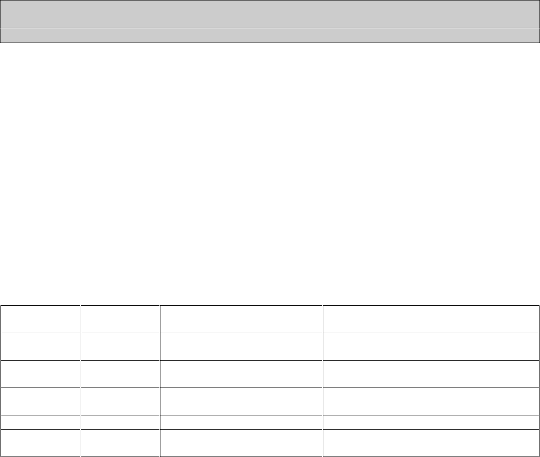
control (Fig. 2, ref 3) to one of the following bands:
Band
Frequency Range
Notes
160
1.8 - 2.1 MHz
80
3.2 - 4.2 MHz
40
6.0 - 7.5 MHz
30
7.5 - 14.5 MHz
USA 30-meter power limit currently 200-watts
20
7.5 –14.5 MHz
17
14.5 –22.0 MHz
15
14.5 –22.0 MHz
12
22.0 –30.0 MHz
Amplifier automatically disables above 25 MHz
10
22.0 –30.0 MHz
Amplifier automatically disables below 28 MHz
6
50.0 –54.0 MHz
Frequency Limits Table 1
Caution: This amplifier has an FCC mandated automatic disconnect and other features preventing 27-MHz
operation. There is no available circuitry or control provision to circumvent this lockout.
MARS or CAP Operation
For licensed amateur radio operators participating in Military Affiliate Radio Systems or CAP, this amplifier is
suitable for use on all frequencies between 1.8 and 54 MHz with some precautions. The upper frequency limits
are in bold type in the table above. Do not operate above the bold-type frequency limits in the table above or PA
(power amplifier) or filter damage may occur.
This amplifier has significantly cleaner output purity than FCC part 97.307 requirements (January 2016) when
operated inside all amateur bands listed in the table above. Ameritron does not guarantee harmonic suppression
or operation in applications outside standard amateur radio bands.
Most non-amateur services prohibit use of non-commercial radio equipment. This amplifier automatically
prevents operation between 25 and 28 MHz. Operation in the 25-28 MHz range is not available with this
product, irrespective of licensing or end-use.
Warning Lights
The ALS-606 has two primary warning lights in the center of the front panel, SWR and PA. When SWR or PA
warnings illuminate from an operating fault, the amplifier defaults to a forced bypass mode. Operational faults
and the forced bypass reset by placing the amplifier in standby.

16
ALC: The yellow ALC light is at the far left of the warning light cluster, next to the ALC control. The yellow
ALC light is not a fault indicator. The ALC light indicates ALC output. Occasional flashing is normal with
properly adjusted ALC. An almost steady ALC light generally indicates too much ALC.
TX: The TX indicator illuminates steady green when the amplifier is “keyed” or in the transmit mode.
The SWR and PA indicators serve exclusively as warnings. The SWR and PA, in conjunction with TX and
Band indicators, flash in certain “codes”to indicate severe operational problems. The following table applies to
faults:
Warning light
Steady
Warning light
Flash
Fault
Cause or Cure
SWR
TX
Antenna Reflected Power
High antenna SWR or intermittent antenna
or feedline connection
SWR, PA
Band
Wrong filter
Filter input SWR
Exciter or amplifier on incompatible band,
filter failure
PA, TX
PA FET too hot
Excessive power for duty cycle or SWR,
lack of proper airflow
10M, PA, TX
Illegal 11 meter
Excessive 27 MHz signal level
REM, PA
No data or bad band data when
on remote
Defective or improper remote cable, or bad
radio band data information

17
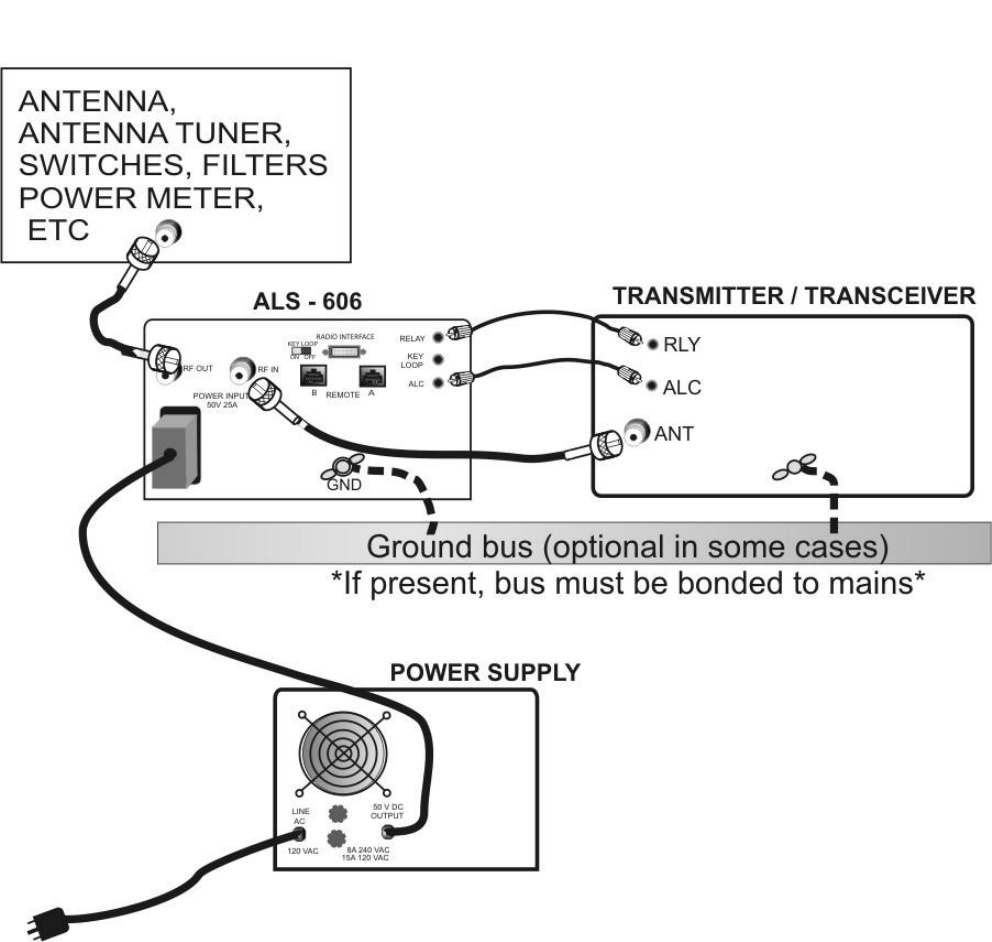
Interconnection Wiring
Interconnections Figure 1
Amplifier Rear Panel
18
50V 25A The power supply must be unplugged from the power mains before installing or removing this connector.
This connector is indexed by a slight vertical offset in the two round index pins. Observe spacing offsets to
correctly mate the pins. Seat the male plug fully onto the amplifier rear panel male connector pins. After
seating, the power supply can be plugged into the AC mains outlet.
ALC Optional connection. Connects to radio ALC input and provides power limiting.
RELAY Connect to radio amplifier keying line. Radio must pull this 12-volt 15mA line below 2 volts to transmit.
GND Connect to station ground bus, if available. This connection is primarily for extra safety.
RF IN Connect through good 50-ohm coaxial cable of any reasonable length to radio’s antenna output connector.
This can be a smaller cable, such as RG-58/U, and should not be needlessly long.
RF OUT To 50-ohm antenna, antenna tuner, or power meter. This is the high power output. 50-ohm coaxial cable
and system beyond this connector must safely handle at least 600-watts.
RADIO INTERFACE This connector is for use with Ameritron radio interface cables. It allows automatic band selection
(following the radio). It also provides amplifier actuation in transmit mode with some radios.
REMOTE These RJ45 connectors are for an Ameritron remote control head, or remote operation with an interface
box. They provide access to controls, including most metering functions.
KEY LOOP Key loop switch and jack are for use with certain automatic antenna tuners. Instructions will be in tuner
manual. Key Loop switch must be off when using remote cable unless using this jack.
1.) If you use a desktop grounding bus system, connect the station ground bus to the amplifier rear panel
wing nut. National safety codes require the station ground electrically bond to the power mains safety
ground at the building entrance. Do not connect the amplifier to its own isolated ground rod or ground
system.
2.) Connect the power supply to the amplifier.
3.) Connect the RELAY line to the transceiver’s amplifier control port. This port is usually described or
defined in the amplifier interfacing section of the radio or transceiver manual. This port must pull low
for transmit, and be open circuit when receiving. Nominal relay control voltage from the ALS-606 is 12
volts positive with only 15 mA current. You should always check your transceiver’s manual, but almost
any standard transceiver directly interfaces with this amplifier.
4.) Connect the RF OUT (output) port to the appropriate point in your station. This is the high power RF
output cable. This connection would go to your (minimum) 600-watt rated Power/SWR meter, antenna,
or antenna matching device. Good quality Mini-8 or RG-8X cables are acceptable for anything but
RTTY use, although larger RG-8 style cables are normally preferred. The antenna matching system, or
antenna tuner, must connect to this port.
5.) Connect the RF IN connector to your transceiver. Do not install any active antenna matching devices on
this port. In general, the shortest and most direct cable connection is best, although high quality cables
can be very long without adverse effect on performance. RG-58/U or Mini-8 (RG-8X) style cables are
acceptable. You should never use a tuner of any type on the amplifier input, nor should you drive this
amplifier with over 100 watts peak envelope power. Never use a non-FCC accepted device with this
amplifier.
19
6.) The ALC line is often not required, but ALC is a useful last resort safety measure. The ALC system
monitors the ALS-606 RF output power and reflected power, and reduces exciter power if power
exceeds front panel ALC control limits.
7.) Operate the bandswitch manually during initial testing. Do not connect band decoders, band data lines,
or computer interfaces until initial tests are completed and the amplifier is functioning normally.
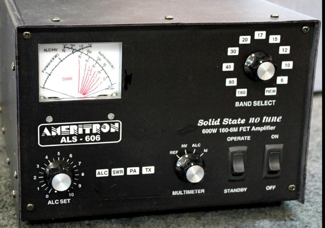
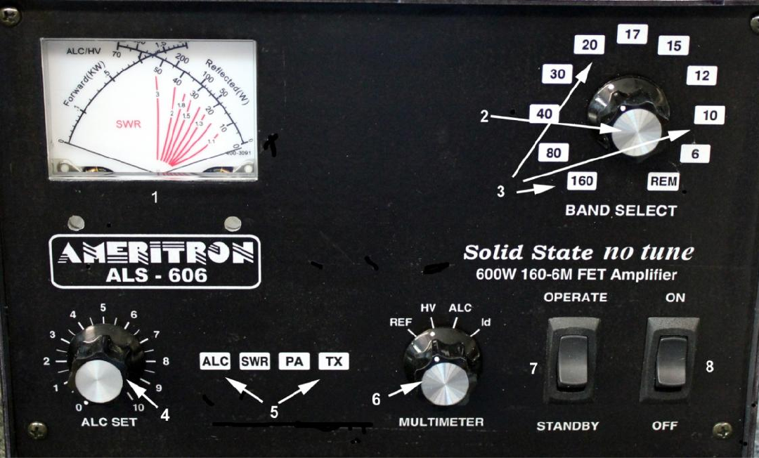
Front Panel
Amplifier Front Figure 2
The front panel contains the following indicators and controls. To prevent damage, become familiar with the front panel
before operating the amplifier.
1.) FET module current, voltage, ALC, and reflected power right scale. Power output left scale. Multimeter (reflected
power, module voltage, ALC, or module current) selected by 6
2.) BAND or REMote selector knob
3.) Backlit BAND or REMote LED indicators, also warning if flashing
4.) ALC limit adjustment
5.) Backlit Function and Fault Warning LED indicators
6.) Multimeter scale function selector knob
7.) Operate and Standby switch, also resets fault warnings
8.) Main Power, also resets power supply overload

20
Note: The meter’s left scale-arc (fig.2 ref 1) continuously indicates forward peak envelope power (PEP) output directly in
kilowatts. It is 100 watts, or 0.1 kW, per meter scale picket. PEP has no fixed relationship to long-term average power
except, for constant amplitude carriers like a steady CW carrier, when PEP and average powers are equal. PEP is the
highest average power during one (or more) radio frequency cycle(s) at the modulation envelope crest.
The meter’s rightmost scale-arc indicates PEP reflected power in watts on the upper scale numbers and pickets. Notice
power meter calibrations are not evenly spaced. Lower scale numbers and pickets are evenly spaced, and are for all other
functions. The lower right scale is used for relative ALC setting, power amplifier module voltage (0-70 volts), and power
amplifier current (0-70 amperes). Nominal voltage is 50 volts; maximum safe current is 25 amperes. Maximum safe
output is 600 watts peak; maximum safe peak reflected power is 125 watts.
Initial Operation
For personal and equipment safety, double-check all wiring and connections (Interconnections fig.1) before
turning power on. After verifying all power supply and amplifier connections, follow the procedures below:
1. Place the MULTIMETER switch (fig.2 ref 6) in the HV position. The multimeter is the right-side scale
on the panel meter (fig.2 ref 1), and reads on the 0-70 right scale bottom. Find 50 on the scale. HV
reading should be approximately 50 volts whenever the amplifier is ON. Any voltage above the Forward
(KW) arc crossing is unsafe.
2. Place the ALC SET control (fig.2 ref 4) full clockwise (10 on knob scale). This sets ALC to engage at
maximum possible power, which effectively will disable the ALC for initial testing.
3. With the STANDBY/OPERATE switch (fig.2 ref 7) on STANDBY, turn the power switch (ref 8) ON.
4. There might be a slightly delayed “click”from the power supply. HV (fig.2, ref 1) should immediately
rise to near full scale. The meter and the appropriate BAND LED (fig.2, ref 3) should illuminate.
5. The multimeter’s HV scale (fig.2, ref 1, lower right scale arc) should indicate approximately 50 volts.
Any voltage above the Forward (KW) arc crossing is unsafe.
6. Rotate the BAND switch (fig.2 ref 2 and 3) through all positions. The appropriate BAND LED will
illuminate, band-filter relays will audibly switch when moving between 160 and 80 meters, 80 and 40
meters, 40 and 30 meters, 20 and 17meters, 15 and 12 meters, and between 10 and 6 meter selector
positions. There should be no filter change moving between 30 and 20, 17 and 15, or 12 and 10-meter
selections since these band groups share a common filter in each pair.
7. Set the BAND switch (fig.2 ref 2) to a band where you have a good 50-ohm high-power load connected.
8. Change the meter switch (fig.2 ref 6) to REF. In this position, the multimeter indicates PEP reflected
power.
9. The next objective is to have a steady unmodulated low-power carrier. With no modulation in the FM,
AM, RTTY, or CW mode, and with the amplifier still on standby, adjust the exciter’s power to about ten
watts. Verify your radio is supplying reduced power, ideally around 10-20 watts carrier (not critical),
21
and that VSWR of the antenna system or load is low. There should be almost no deflection on the
reflected power scale (fig.1 ref 1) with the MULTIMETER switch in the REF position. If the meter
indicates noticeable reflected power, check the RF cables or antenna system. Reminder: You cannot
use a tuner in your radio or between your radio and this amplifier to match the antenna system.
Any antenna matching must be between the amplifier and the antenna, and the antenna tuner and
everything else connected beyond the amplifier must conservatively handle 600 watts of both
carrier and peak envelope power.
10. Place the amplifier in OPERATE position (fig.2 ref 7). Be sure the amplifier BAND SELECT (fig.2 ref
3) matches the band selected on the transceiver.
11. Place the transmitter or transceiver into transmit in FM, AM, RTTY, or CW modes. The green TX LED
(fig.2 ref 5) should light. The Forward (KW) power scale (fig.2 ref 1) should increase to very roughly
ten times the initial exciter power reading. Reflected power should remain very low, and the PA current
should increase on the right meter 0-70 scale (fig.2 ref 1) when in the Id Multimeter position. Only the
TX and BAND SELECT LED’s should illuminate.
12. Briefly, increase exciter power until the amplifier reaches 600-watts output, or increase power until the
exciter reaches maximum power without exceeding 600-watts amplifier power. Watch the Id
MULTIMETER position on the right meter 0-70 scale, and never exceed 30 amperes. Target Id reading
is 25 amperes or less.
13. After verifying all of this, and understanding control locations and function, the amplifier is ready to
operate.
This amplifier produces approximately 600-watts PEP output power with approximately 70-watts PEP drive.
This is nominal power, and can vary slightly from band-to-band.
ALC Adjustment
It is unfortunate, but radio manufacturers do not have standardized interfaces. Because of this, ALC requires
some initial adjustment. If the ALC voltage is too low, the ALC will not provide good control of power levels.
If the ALC loop gain is too high, the ALC can cause a “power bounce”as power attempts to settle at the desired
ALC power threshold. This overshoot, dip, and recovery is caused by slow radio ALC response time. Excessive
ALC control loop gain aggravates power bounce.
ALC attack bounce shows on a steady carrier (such as RTTY, CW, or FM) as a high initial peak power reading
followed by a deep null. The deep null is followed by a slow settling to the desired power level. On SSB, it will
show as a slow warble or modulation of power levels, especially at the very start of voice transmissions.
If ALC attack bounce is observed, the ALS-606 will require ALC gain adjustment. The ALS-606 has a small
flat-blade screwdriver adjustment for setting ALC gain. This adjustment is accessible through a small hole
located on the left cabinet side behind the front panel, near the panel meter.
22
ALS-606 Functional Overview
The ALS-606 is an amateur radio multiband radio frequency linear power amplifier with 600 watts PEP
nominal output. This device complies with technical standards of FCC rules, CFR Title 47 part 97.317(a) and
(b).
General Operation
This linear amplifier covers the 160, 80, 40, 30, 20, 17, 15, 12, 10, and 6-meter amateur bands. It typically
requires 50-watts to 75-watts drive power. When power is off or when the amplifier is not in transmitting mode,
internal relays bypass the amplifier. When power is ON and the standby switch is in the OPERATE position,
and when the rear panel RELAY control line is held low (below 1 volt), exciter power is routed through input
relay RLY1 to the PD8m power attenuator board.
ATTENUATOR BOARD
The attenuator board has two 3dB attenuators. A relay switches one attenuator out on six meters. This makes
amplifier drive power requirements more consistent across the operating frequency range.
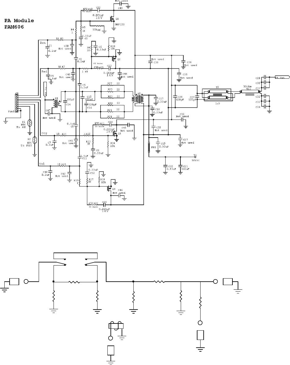
PA Amplifier
Power amplification comes from a single 600-watt power amplifier module. The PA module (PAM-606) uses
four MFR-150 field effect transistors. Bias each MRF-150 at an equal quiescent current within the range of 100
mA to 300 mA. It is important to bias each FET the same. IMD performance changes very little within this bias
range. Transistor conduction angle is slightly over 180-degrees, providing linear class-AB operation. Normal dc
drain operating voltage is approximately 50 volts. The linear supply is unregulated, and can run as high as 60
volts without harm, although it is much better to keep voltage below 56 volts. See the power supply manual.
Unlike the standard Motorola based modules, the PAM-606 module uses two diametrically opposed push-pull
pairs. This shortens ground path distance while simultaneously reducing circuit board groundplane current
levels. This greatly improves VHF performance. The dual diametrically opposed push-pull pairs drive balanced
low impedance striplines. The balanced striplines parallel at a unique 1:9 broadband matching transformer.
The linear RF power FET’s mount on a forced-air-cooled aluminum heatsink. Two dc fans cool the PAM-606
module and heatsink. Thermistor (PAM-606, R2) senses power amplifier transistor flange temperature.
Transistor temperature thermistor R2 regulates bias voltage, reducing bias voltage as transistor temperature
increases. This bias feedback system keeps transistor quiescent current stable independent of transistor junction
temperatures. PAM-606 thermistor R2 also feeds a comparator. The comparator removes drive when transistor
temperatures approach unsafe levels.
A second thermistor (PAM-606 R1) monitors heatsink temperature. Voltage at thermistor R1 regulates fan
speed, increasing fan speed and airflow as the heat sink warms.
PAM-606 module bias comes from the CB-2 control board assembly. Each transistor has an individual bias
adjustment, with minimum bias counter-clockwise from the top view.
The PAM-606 module employs significant negative feedback to reduce gain, improve gain flatness, improve
linearity, and ensure stability. The FET’s have direct resistive voltage feedback across each individual transistor
from drain-to-gate, as well as push-pull transformer (T2) coupled feedback common to the push-pull circuit.
Push-pull operation, negative feedback, and linear biasing of FET’s provide significant pre-filter harmonic
suppression.
23
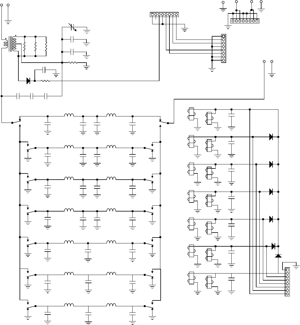
1KWF6 Low Pass Filter Assembly
The PAM-606 module connects directly to the 1KWF6 circuit board assembly through a 50-ohm cable. Power
enters the filter system through a directional coupler consisting of current transformer T2, capacitors C36-38,
C40-42, and resistors R4, 5 and 6. This directional coupler detects termination errors at the filter’s power
amplifier side. These errors include filter band errors. A comparator on the CB2 control board monitors
directional coupler termination errors. Any significant filter or antenna reflected power error disables the
amplifier. Such errors normally come from selecting the wrong filter for the exciter’s operating band, or having
a poor load SWR on the amplifier.
The filter board directional coupler output routes through one of seven 5-pole lowpass filter groups. Relays,
controlled by CB2 control board logic, select appropriate lowpass filter components.
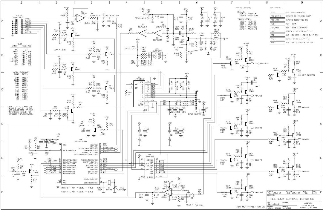
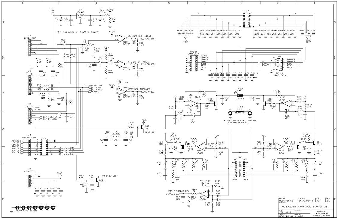
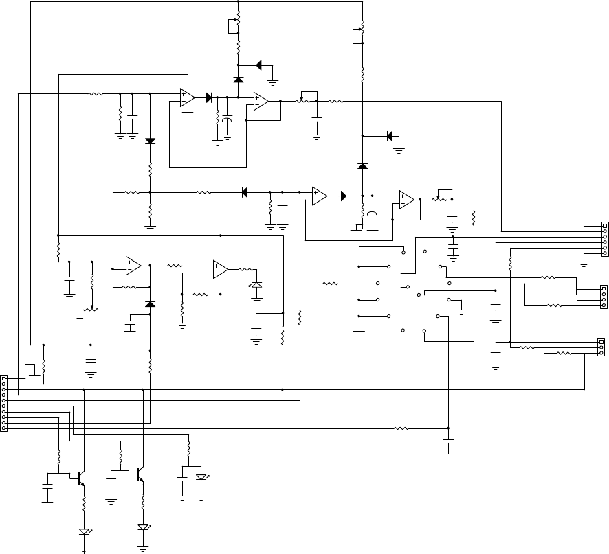
Control and Protection Logic
The CB2 control board contains all protection and control logic. In the event of an operational fault, the CB2
locks out the amplifier and illuminates the proper front panel warning light sequence. The CB2 also contains
bias, relay sequencing, and fan speed controls.
The CB2 board contains band-decoding systems, and automatically disables operation between 25 and 28 MHz
in all ALS-606 amplifiers. The embedded 25-28 MHz lockout function cannot be disabled or changed.
SWR Directional Coupler
The rear panel directional coupler board samples line current and line voltage, vector summing line voltage and
current samples before conversion to a dc output voltage. The resulting forward and reflected voltage represents
forward and reflected power. The ratio of forward to reflected samples represent mismatch from ideal 50-ohm
loads.
Circuit Boards
There are ten basic circuit boards plus one power amplifier modules in the ALS-606. The text below gives a
brief description of each board’s function.
1KWF6
The 1KWF6 is a 1kW rated low-pass filter. It is the very large topmost board with several large toroids and air
wound inductors. This board contains filter input SWR fault detection and seven low-pass 5-pole filters.
Additionally, antenna relay board RLY attaches directly to the 1KWF6 board.
CB2
The CB2 is located on the amplifier side between the band selector and power jack, below the attenuator board.
The CB2 control board provides most control functions, including bias, fan speed, overload, wrong-band
protection, and transmit-receive relay sequencing. It is the hub for nearly all functions, including external
interfaces, power metering, and 12-volt busses.
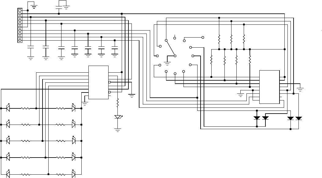
BSW3
The BSW3 is located behind the BAND switch. It provides all band selection functions, as well as
bandindicators.
24
MB1
The MB1 is located behind the front panel below the meter. It contains peak-envelope-power detection circuits,
multi-meter switching, fault indicators, and ALC circuitry. There are four power meter adjustments on this
board; forward power, reflected power, forward peak hold time, and reflected peak hold time. Shunts on a
header, located on the board’s upper edge, adjust panel meter brightness. This board also contains an ALC gain
adjustment, which limits ALC voltage.
PA Module and Board
The PA board, along with a large forced-air cooled heatsink, forms a PA module. FET’s are gain matched at the
factory, and replacement FET’s must be gain matched. This board does not have adjustments; bias adjustments
are located on the CB2. The power amplifier module (located between the filter chassis and the cabinet bottom)
is accessible by removing the amplifier bottom cover only. The cabinet cover must remain in place to support
the rest of the sheet metal.
PD8m
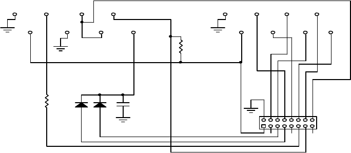
RJ45
The RJ45 board mounts on the rear panel. It contains two RJ-45 jacks for remote control interface.
RLY
The RLY board contains independent transmit and receive relays, one for RF output switching and the other for
RF input switching. T/R relays activate with a low on terminals K (key) J1-3 and RJ1-7. The CB2 board
contains relay timing logic.
SWR
The SWR board is on the rear panel in front of the RF output connector. It is a traditional 50-ohm directional
coupler. The null adjustment is accessible through a rear panel hole.
The PD8m is located on the right side of the amplifier just above the panel containing the cooling fans. This
board is slightly reconfigured from the PD8 used in the ALS1306 through removal of the matching transformer
and combiner. The PD8m contains two ~3dB attenuator pads. One attenuator switches out to increase six
metergain. Do not modify, remove, or bypass the attenuators.
25
Schematics
Filter 1KWF6
1KWF6 output filter Figure 3
10 Meters
15 Meters
20 Meters
40 Meters
80 Meters
160 Meters
54 MHz
2.4 MHz
32 MHz
22 MHz
15 MHz
8 MHz
4.2 MHz
09/20/13
1KWF Rev0.1
C31
27pF
C30
27pF
C29
27pF
C35
0.01uF
C28
0.1uF
C34
250V 12-90pF
C33
220pF
RL1 RL2
L1
16T L2
16T
C2
2700
C1
1500 C3
1500
RL3 RL4
L3
11T L4
11T
C5
1500
C4
680 C6
680
RL5 RL6
L5
12T L6
12T
C8
680
C7
360 C9
360
RL7 RL8
L7
8T L8
8T
C11a
270 C11
270
C10
270 C12
270
C15
180
C13
180 C14
180
C14a
180
L10
6.5T
L9
6.5T RL10RL9
C18C16 C17
C17a
L12
5.5
L11
5.5 RLY12RLY11
C21C19 C20
C20a
H1
RADIO PA IN
L14
RLY14
L13
RLY13
RL2
RL1
RL3 RL4
RL6
RL5
RL8
RL7
RL10
RL9
RL12
RL11
RL14
RL13
C27
0.1uF
C26
0.1uF
C25
0.1uF
C24
0.1uF
C23
0.1uF
C22
0.1uF
D7
D6
D5
D4
D3
J1
D2
D1
1401
C32
150pF
FromPA
T1
Rly Board
J2
H2
R2
1.5k
R6
150
R5
150
R1
10k
R4
150
26
**J1**
1 G
2 5V+
3 RCK
4 SCK
5 SER
6 G
7 D
8 C
9 B
10 A
Band Switch BSW3 Rev0 04/30/14
C3
.001uF
C2
.001uF
LED9
10
LED10
6
LED8
12 LED7
15
LED6
17 LED5
20
LED4
30 LED3
40
LED2
80 LED1
160
1QB
2QC
3QD
6QG
7QH
8GND 9
Q'H
11
SCK
12
RCK
14
SER
15
QA
16
VCC
4QE
5QF
13
G
10
SCLR
U2
74HC595
LED11
REMOTE
C8
.1uF
C7
.1uF
C6
.1uF
C5
.1uF
C4
.001uF
C1
.1uF
D3
914
D4
914 D1
914
14
25
36
47
5EI
6A2
7A1
8GND 9
A0
10
0
11
1
12
2
13
3
14
GS
15
EO
16
VCC
U1
74HC148
D2
914
Remote
N/C
12
6
39SW1
J1
R102.2k R92.2k
R82.2k R72.2k
R62.2k R52.2k
R42.2k R32.2k
R22.2k R12.2k
R11
2.2k
R16
10k R17
10k R18
10k
R15
10k
R14
10k
R13
10k
R12
10k
BSW3 bandswitch figure 4
Bandswitch BSW3
27
Control Board CB2
28
CB2 control board Figure 5
29
Metering Board MB1
MB1 ALC/metering board Figure 6
MB1 Rev3 090227
PIN 1...GND
2...FWD
3...MM -
4...MM +
5...LMP
6...GND
+
-
CTRL
J1
METER BRIGHTNESS
J4
PIN 1...V2
2...V2
3...V1
4...V1
PIN 1...GND
2...12 -
3...12 +
4...FWD PWR
5...RFLCTD PWR
6...TRANSMIT LED
7...COMBINER LED
8...SWR LED
9...ALC VOLTAGE OUT
10...COMBINER LVL
12
11
10
9
8
7
6
5
4
3
2
1
1,2 low
2,3 high
MULTI METER
J2
CURRENT
J3
+12
-12V
8
4
PEAK METER / ALC
ALC
7
5
6
3
2
1
31
25
67
10
98
12
13 14
SW 1
8V 8V
-12V
+12V+12V
8V
-12V
-
+
T
CL
A
S
C
11
4
G
L
F
F w d
R e f
Gn d
Gn d
MULTI METER
CURRENT
METER BRIGHTNESS
REF CAL
REF SPEED
CAL
FWD SPEED
CTRL
-
+
C14
.1
D3
LED1
D2
LED2
Q1
2N3904
C15
.1
Q2
2N3904
D1
LED3
D6
1N916
D2
1N916
C16
.1
D4
LED4
C12
.1
C7
.1
U2B LM358
U1A
LM324
R39
10k 10%
+
C4
2.2uF
+
C3
2.2
U1C
U2A
U1D
U1B
R16 1m 40%
R15
1m 40%
C17
.1
C13
.1
R
C
V1
V2
R
C
AV1
A
V2
C5
.1
J2
J3
J4
R2
2.5k 40% C2
.1
D3
1N916
C8
.01
D1
1N916
J1
C6
.1
C1
.1
R1
2.5k 40%
D4
1N916
D5
1N916
C9
.01
C10
.1
D7
1N916
C11
.1
D8
1N916
D9
1N916
R22
1k
R40
1k
R23
47k
R41
1k
R24
47k
R28
10k
R19
10
R31
1m
R34
220K
R29
1k
R38
4.7K
R32
1k
R7
10
R11
68K
R10
68K
R13
1k R14
1k
R3
5.6k
R6
1m
R18
4.7k
R20
4.7k
R12
10
R21
100
R4
5.6k
R8
1M
R9
10k
R17
4.7k
R5
10k
R33
220k
R26
560
R25
1k
R27
1k R30
6.8k
R35
100k
R37
1k
R36
1k
30
PA Module
PAM power amplifier module Figure 7
Power Attenuator PD8m
06/11/15
PD8M Rev0
-5db Attenuator
RLY1
X1
RLY1
Control
Frequency
IN
OUT to PA
2W MOX
R8
4.7K
R5
27
R4
200 R6
200
R3
200
R2
27
R1
200
PD8m attenuator Figure 8
31
Interface Connections RJ45
RJ45 interface Figure 9
- J1 -
RJ45 Rev0 090217
- J2 -
C1
0.1uF
D2D1
J3
CONN
Pin1
Pin2
Pin7 Pin5 Pin3
Pin4
Pin8 Pin6
Pin1
Pin2
Pin7 Pin5 Pin3
Pin4
Pin6
Pin8
1/2W
R2
560
R1
1k
32
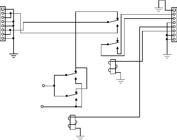
Relay Board
RLY antenna relay Figure 10
Reference figures and drawings
Tables
Frequency Limits Table 1 ..................................................................................................................................... 15
PA OUT
HD1 HD4
RL4
RL1
ANTENNA
RADIO
PA IN
RLA 081210
MAY 21, 2008
Interconnections Figure 1 ..................................................................................................................................... 17
Amplifier Front Figure 2....................................................................................................................................... 19
2KWF6 output filter Figure 3 ............................................................................................................................... 25
BSW3 bandswitch figure 4 ...................................................................................................................................26
CB2 control board Figure 5 ..................................................................................................................................28
MB1 alc/metering board Figure 6....................................................................................................................29
PAM power amplifier module Figure 7...............................................................................................................30
PD8m attenuator Figure 8 .................................................................................................................................... 30
RJ45 interface Figure 9........................................................................................................................................31
RLY antenna relay Figure 10..............................................................................................................................32
33