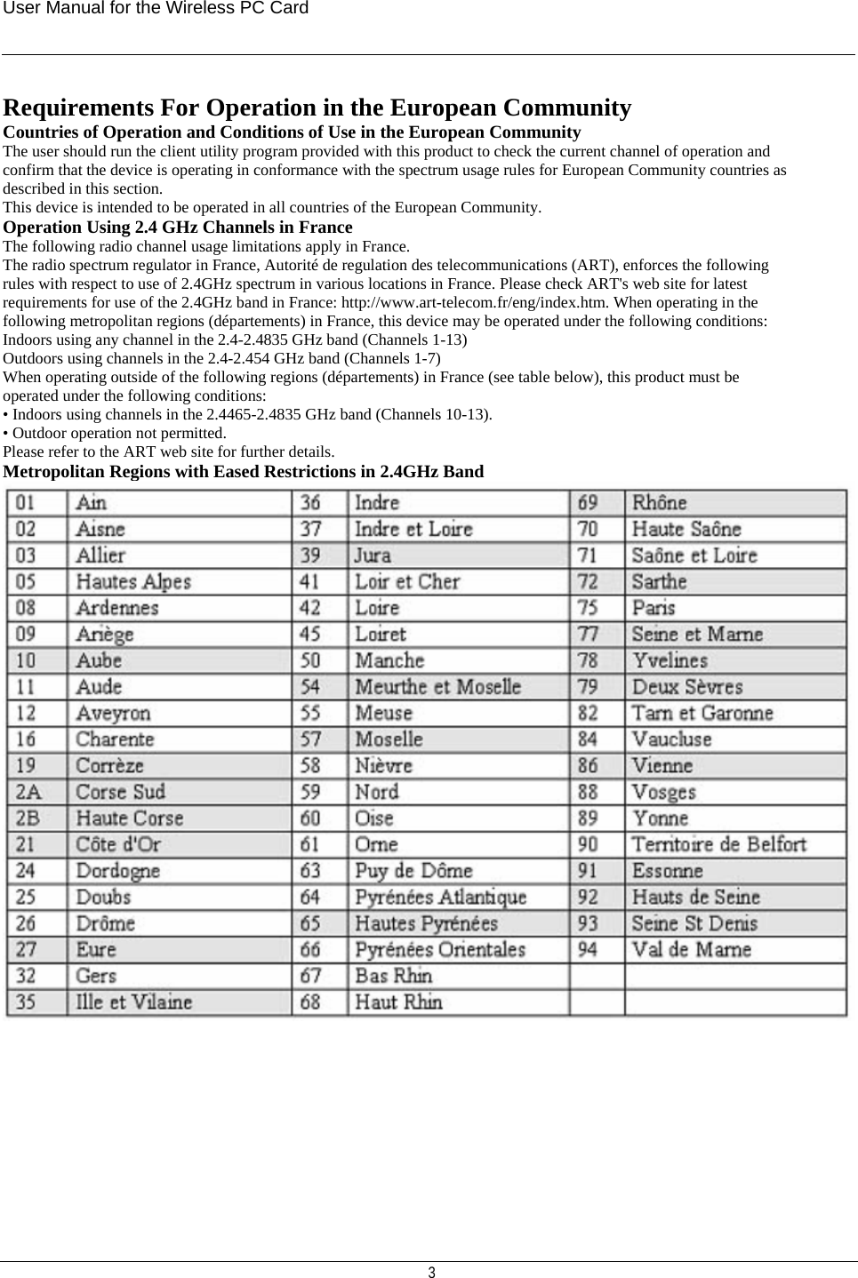
Amigo Technology AWI-922W IEEE 802.11g WIRELESS MINI PCI ADAPTER User Manual
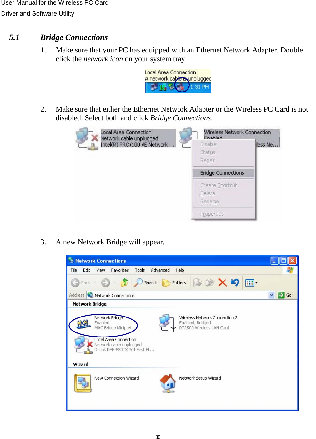
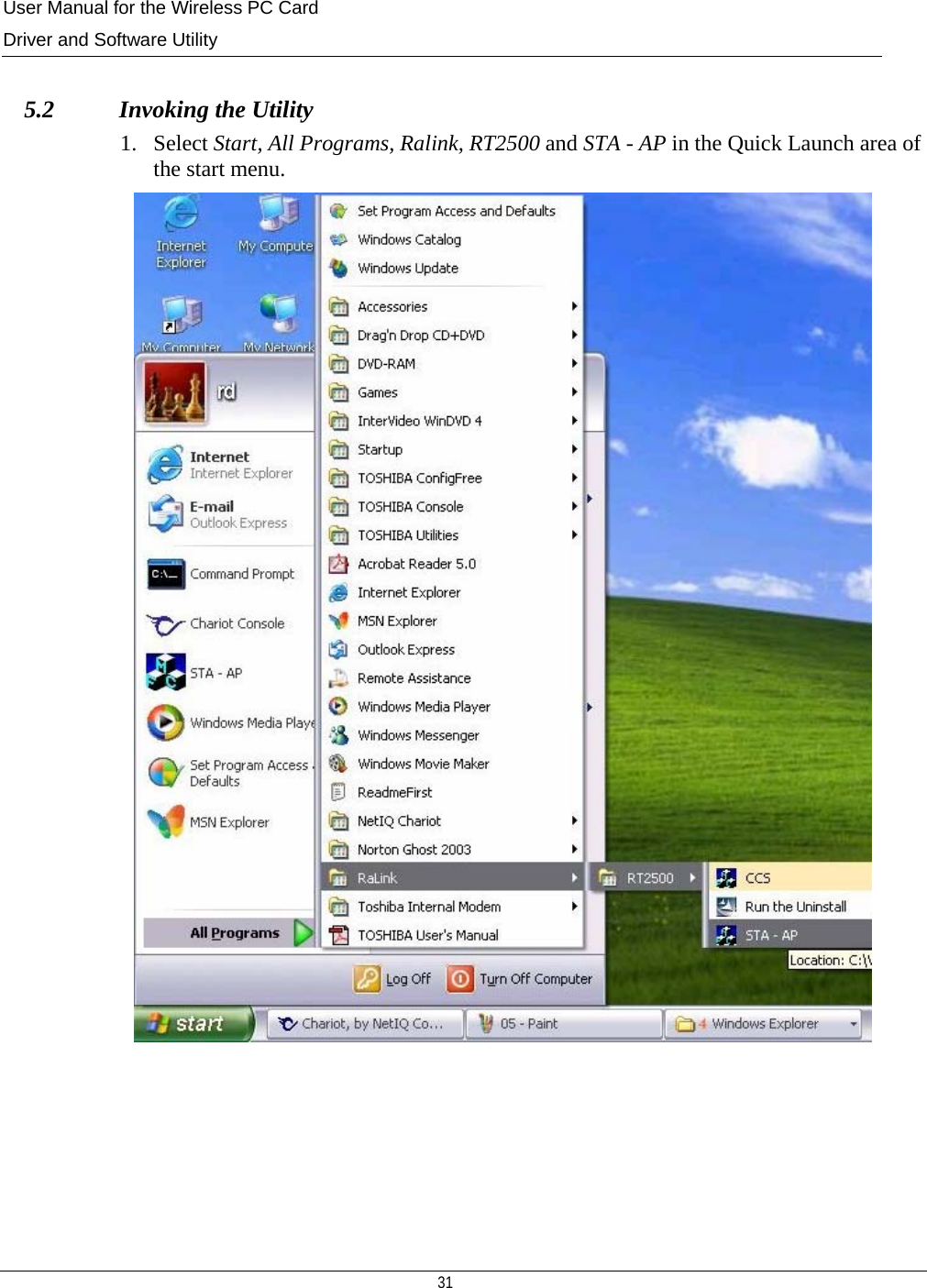
Amigo Technology Inc. IEEE 802.11g WIRELESS MINI PCI ADAPTER
UserManual.wiki
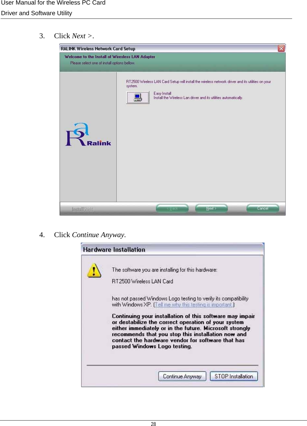
>
Amigo Technology
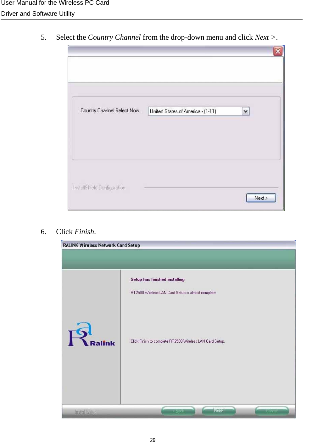
>
AWI 922W User Manual
UESRS MANUAL
Navigation menu
Upload a User Manual
Namespaces
Wiki Guide
HTML
PDF
Info
Views
User Manual
Discussion / Help
Navigation


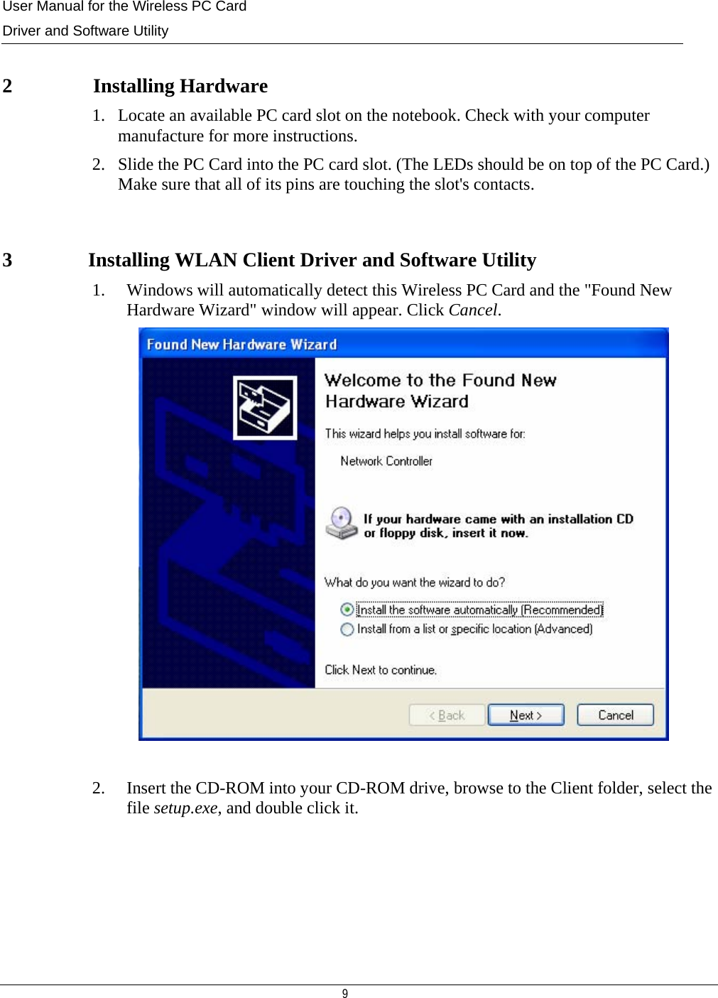
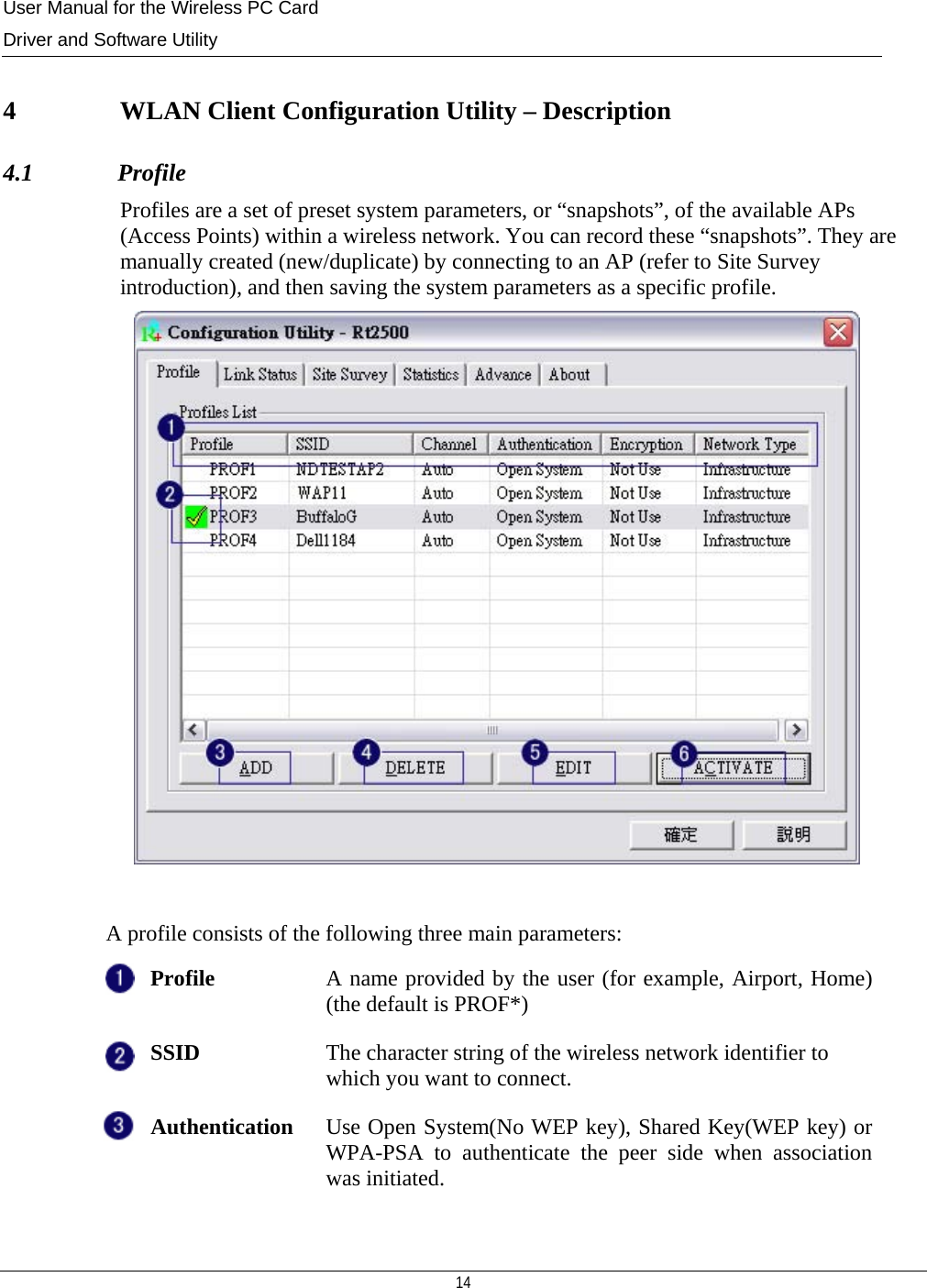
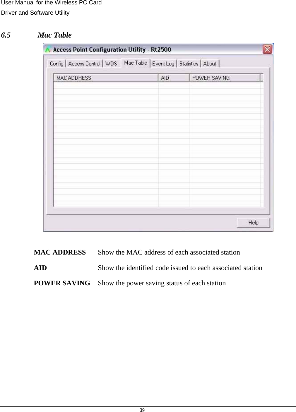
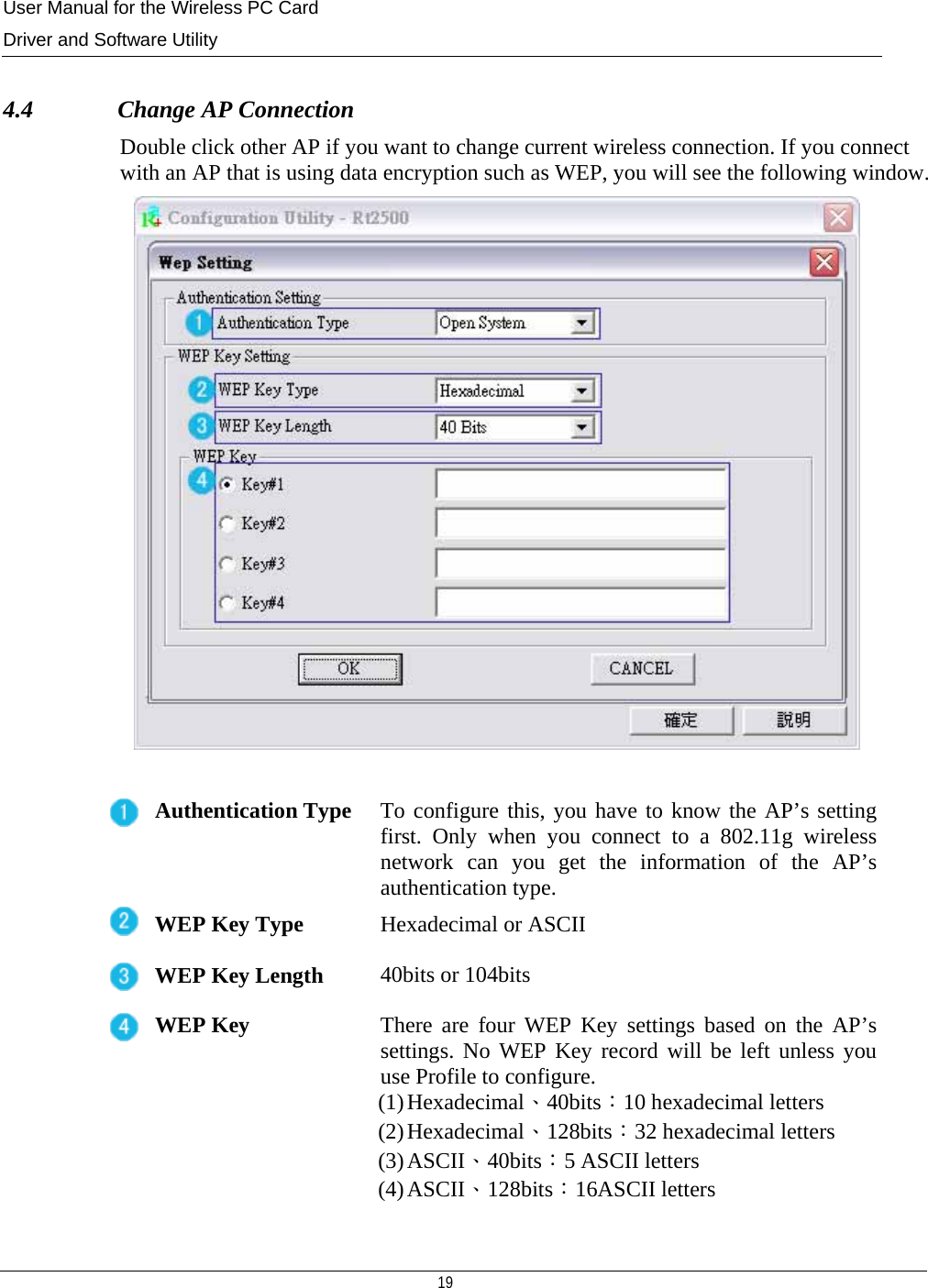
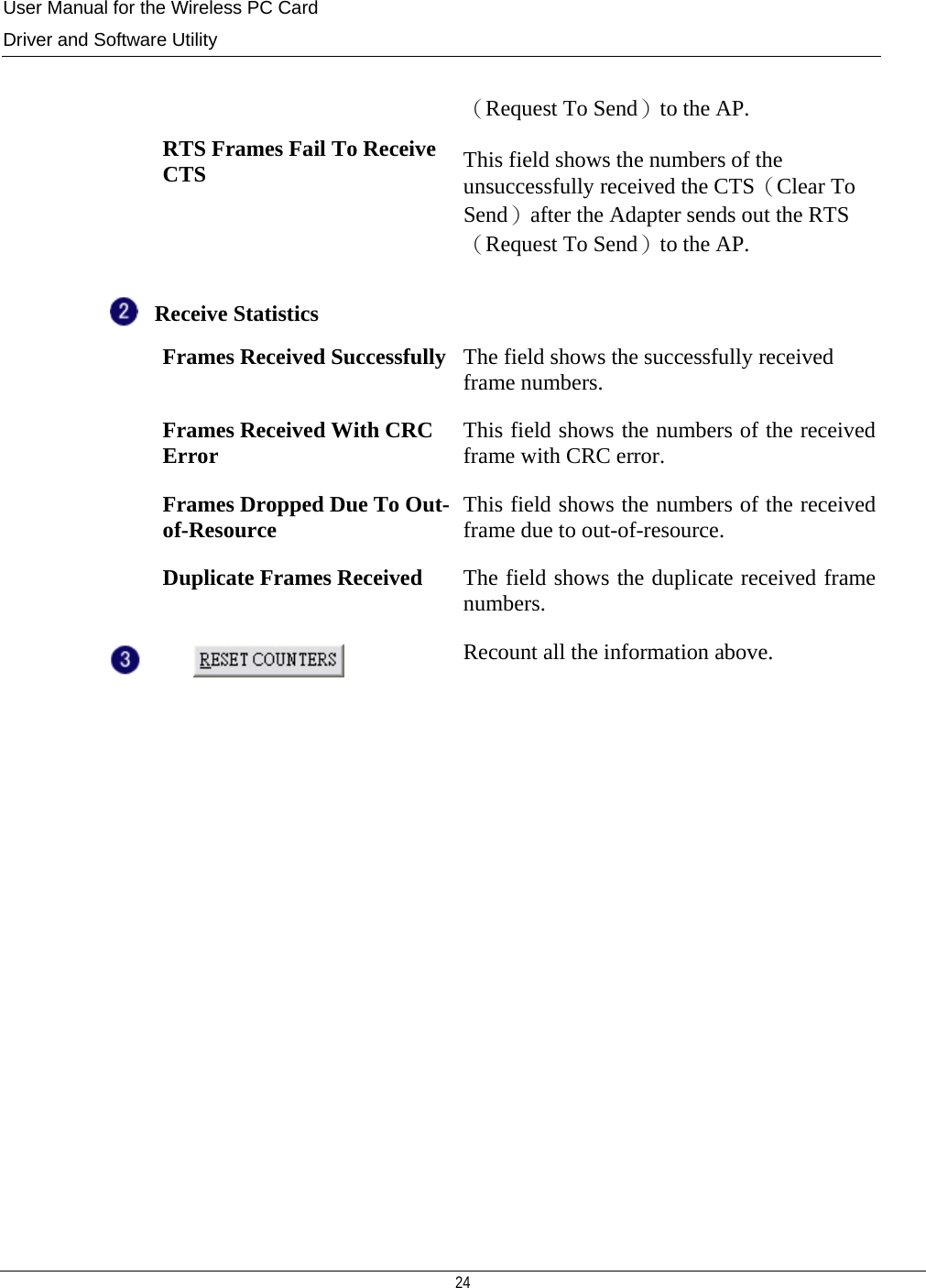
![User Manual for the Wireless PC Card Driver and Software Utility 15 Encryption AP’s encryption type including WEP、AES、TKIP and NOT USE Channel This is the radio channel through which the access point communicates to stations in its BSS. A Basic Service Set (BSS) consists of a group of wireless stations, and an access point that is directly connected to the wired LAN. To establish an adhoc network, make sure the [Channel] is set to the same radio channel as that used by the other wireless clients in your group. However, if you are connecting to a network via an access point, the adapter will automatically synchronize up to the same channel as that used by the access point. Note: The available channel settings are limited to local regulations, which determine the number of channels that are available. FCC: 11 channels MKK: 14 channels Network Type Set the station operation mode to "802.11 Ad Hoc" for network configurations that do not have an access point, or to "Infrastructure" for configurations with an access point. Establish wireless connection with the AP Fail to establish wireless connection with the AP Add a new AP profile (for example, SSID, channel, etc) Delete an existing AP profile Edit an existing AP profile Activate the profile with which the Access point or station you want to associate. The activated profile is the default profile that this Wireless PC Card firstly applies to when this utility program starts running.](https://usermanual.wiki/Amigo-Technology/AWI-922W/User-Guide-484108-Page-16.png)
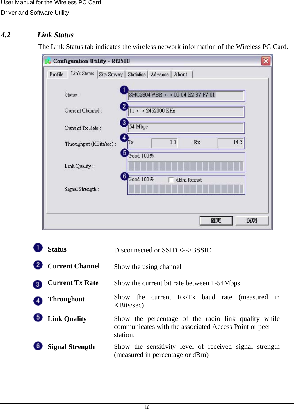
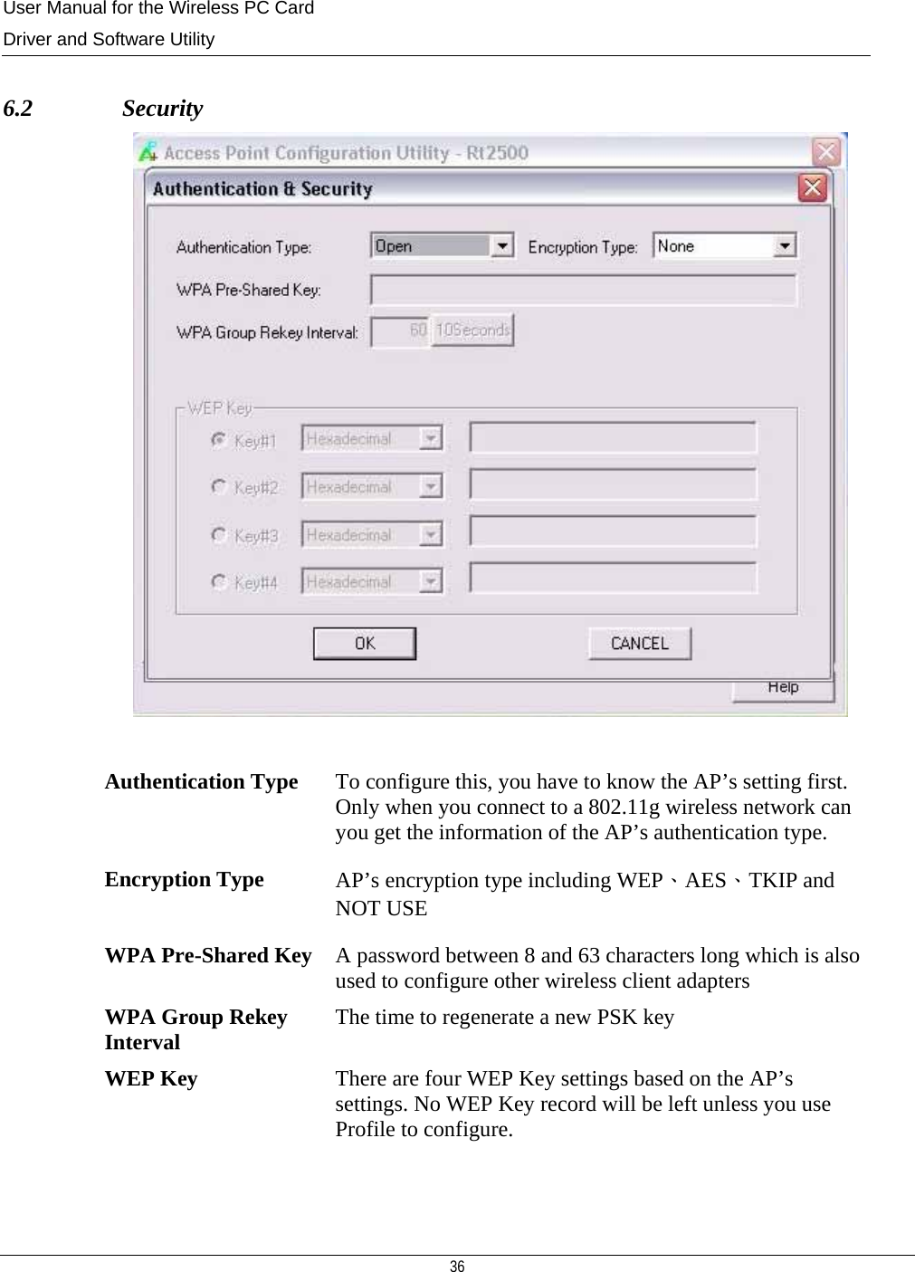
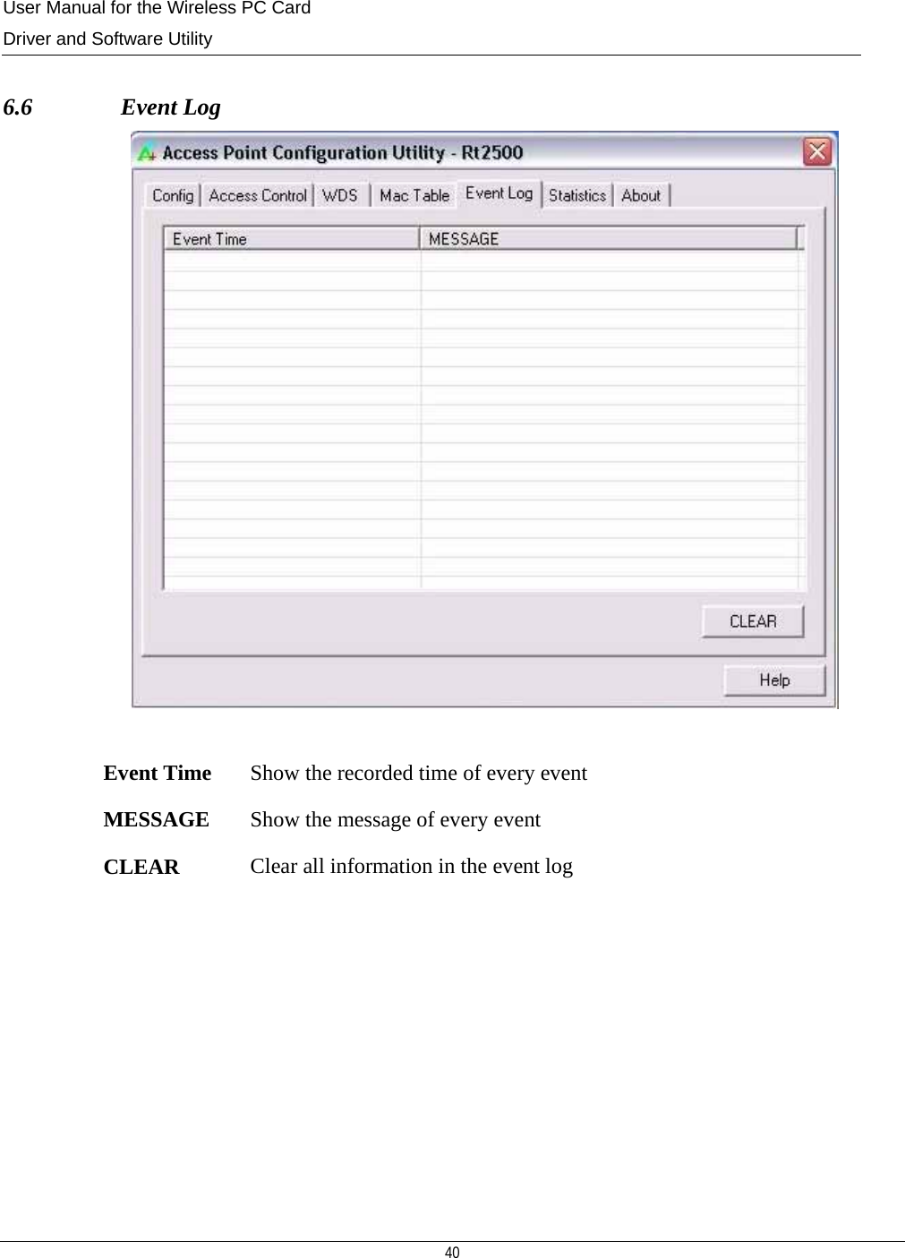
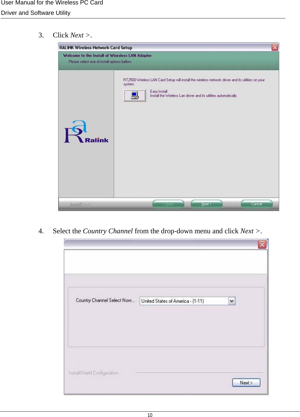
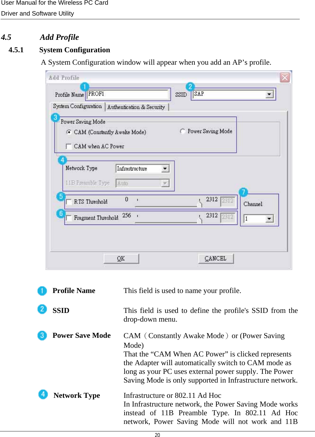
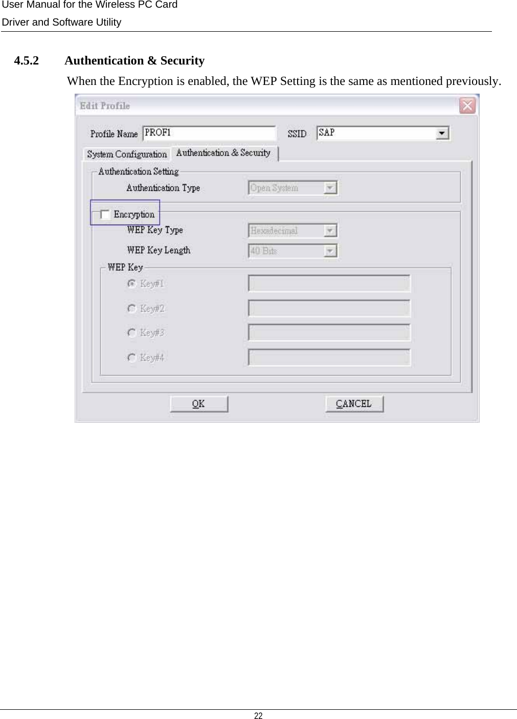
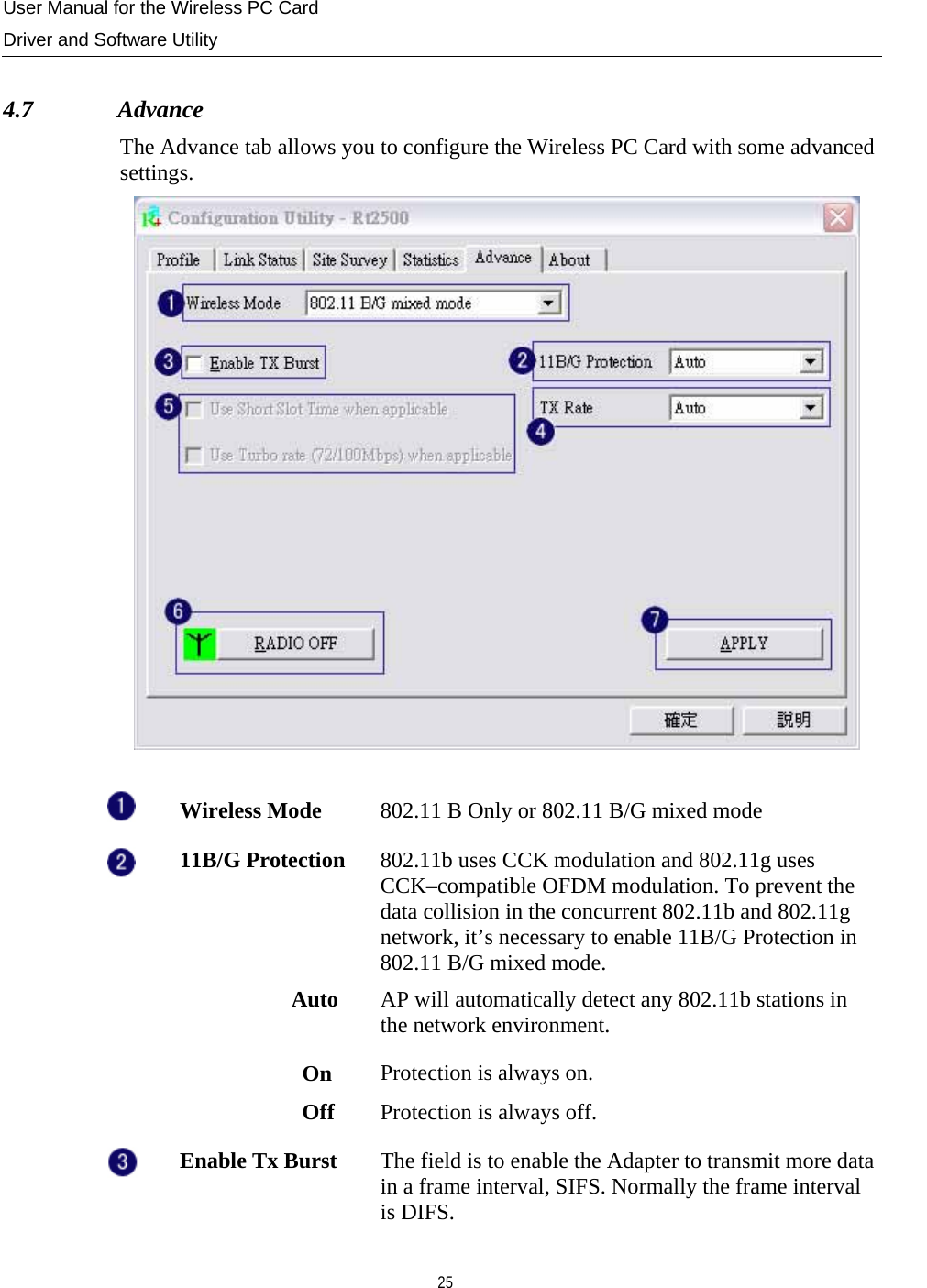
![User Manual for the Wireless PC Card Driver and Software Utility 18 Encryption AP’s encryption type including WEP、AES、TKIP and NOT USE Cannel This is the radio channel through which the access point communicates to stations in its BSS. A Basic Service Set (BSS) consists of a group of wireless stations, and an access point that is directly connected to the wired LAN. To establish an adhoc network, make sure the [Channel] is set to the same radio channel as that used by the other wireless clients in your group. However, if you are connecting to a network via an access point, the adapter will automatically synchronize up to the same channel as that used by the access point. Note: The available channel settings are limited to local regulations, which determine the number of channels that are available. FCC: 11 channels MKK: 14 channels Network Type AP’s network topology including Infrastructure and Ad Hoc Connection is established Show the status of wireless network connection and the SSID Update all APs’ information Connect with an AP Add an new AP’s profile](https://usermanual.wiki/Amigo-Technology/AWI-922W/User-Guide-484108-Page-19.png)
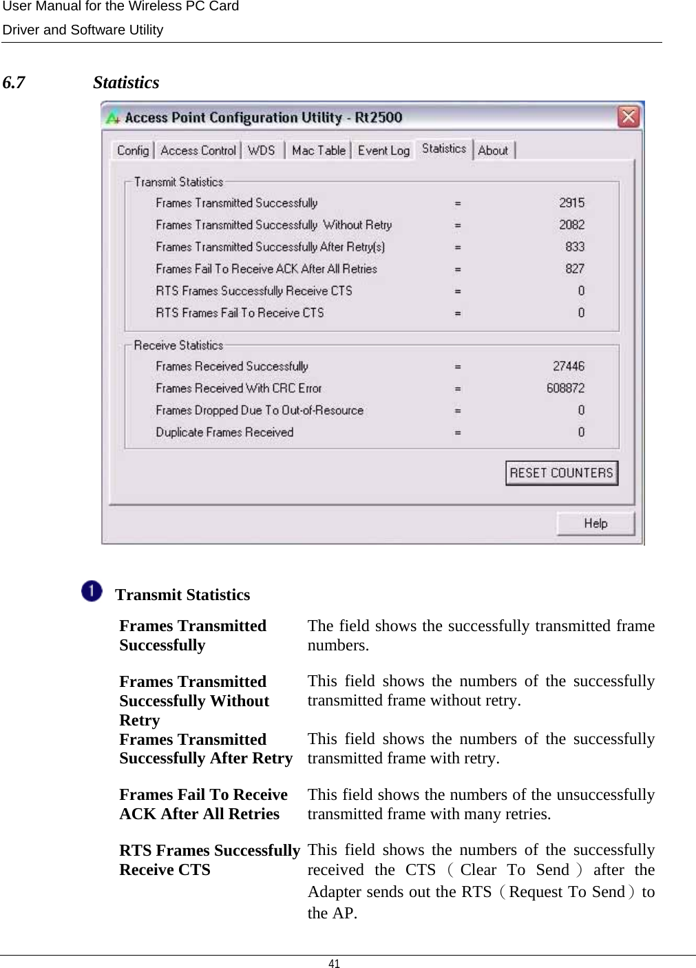
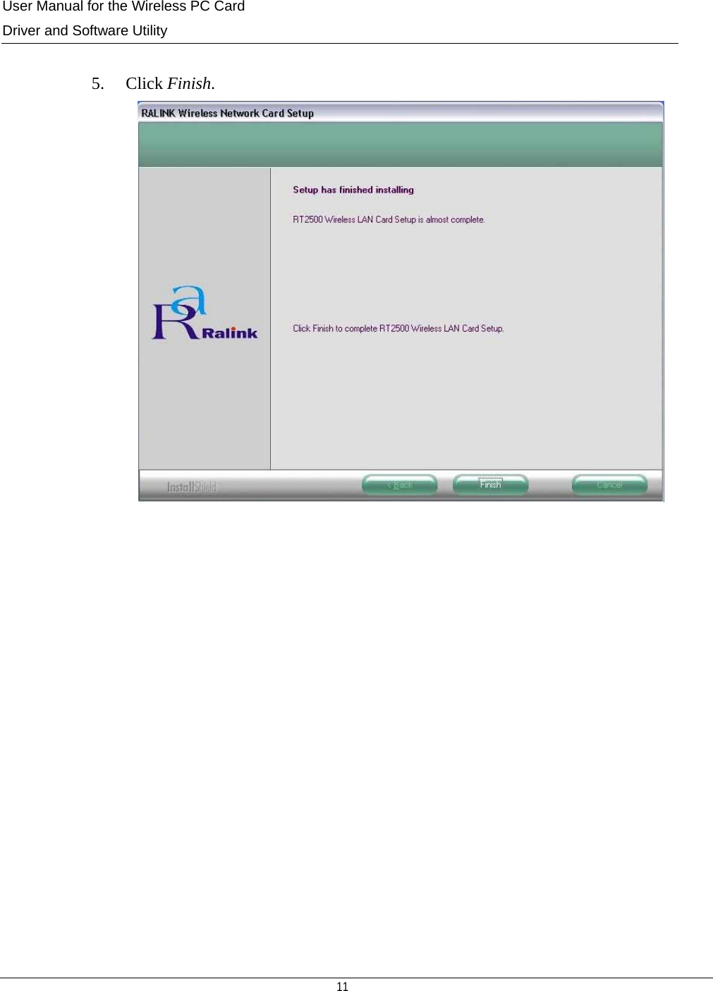
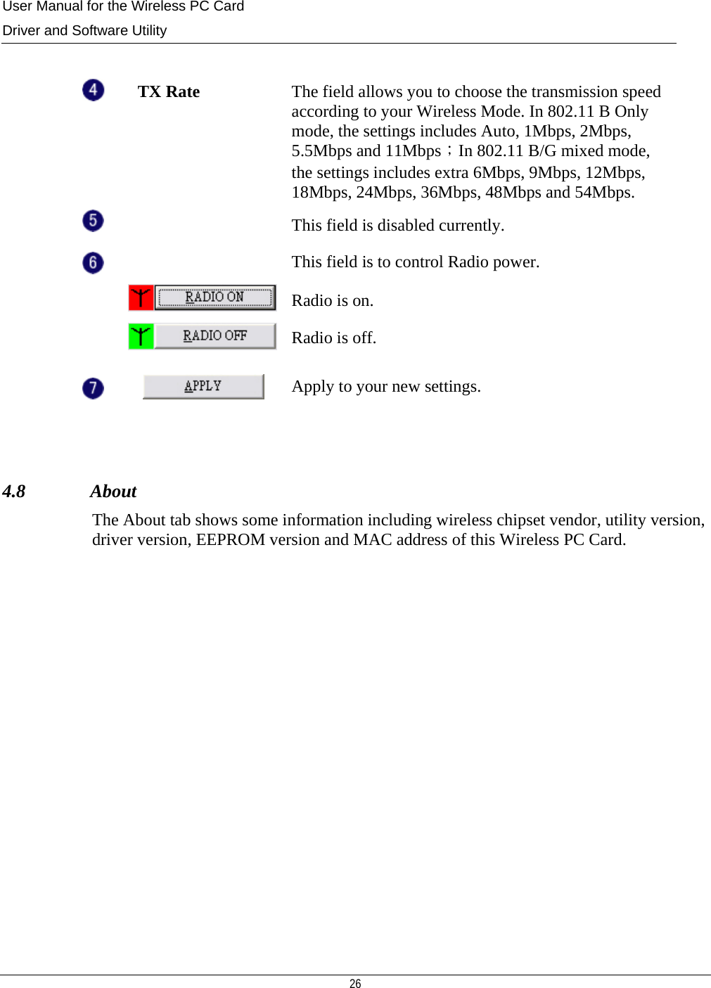
![User Manual for the Wireless PC Card Driver and Software Utility 21 Preamble Type as well as the Channel options will work.RTS Threshold RTS Threshold is a wireless network mechanism designed to prevent the Hidden Node issue , a problem happens in the wireless network when two wireless adapters served by the same AP can’t communicate each other or have collision. Normally, the value of RTS Threshold is needless to change. The default value is 2312. Fragment Threshold Enable to increase the transmission efficiency by split mechanism. The value of Fragment Threshold is 2312. Channel This is the radio channel through which the access point communicates to stations in its BSS. A Basic Service Set (BSS) consists of a group of wireless stations, and an access point that is directly connected to the wired LAN.To establish an adhoc network, make sure the [Channel] is set to the same radio channel as that used by the other wireless clients in your group. However, if you are connecting to a network via an access point, the adapter will automatically synchronize up to the same channel as that used by the access point. Note: The available channel settings are limited to local regulations, which determine the number of channels that are available. FCC: 11 channels MKK: 14 channels](https://usermanual.wiki/Amigo-Technology/AWI-922W/User-Guide-484108-Page-22.png)
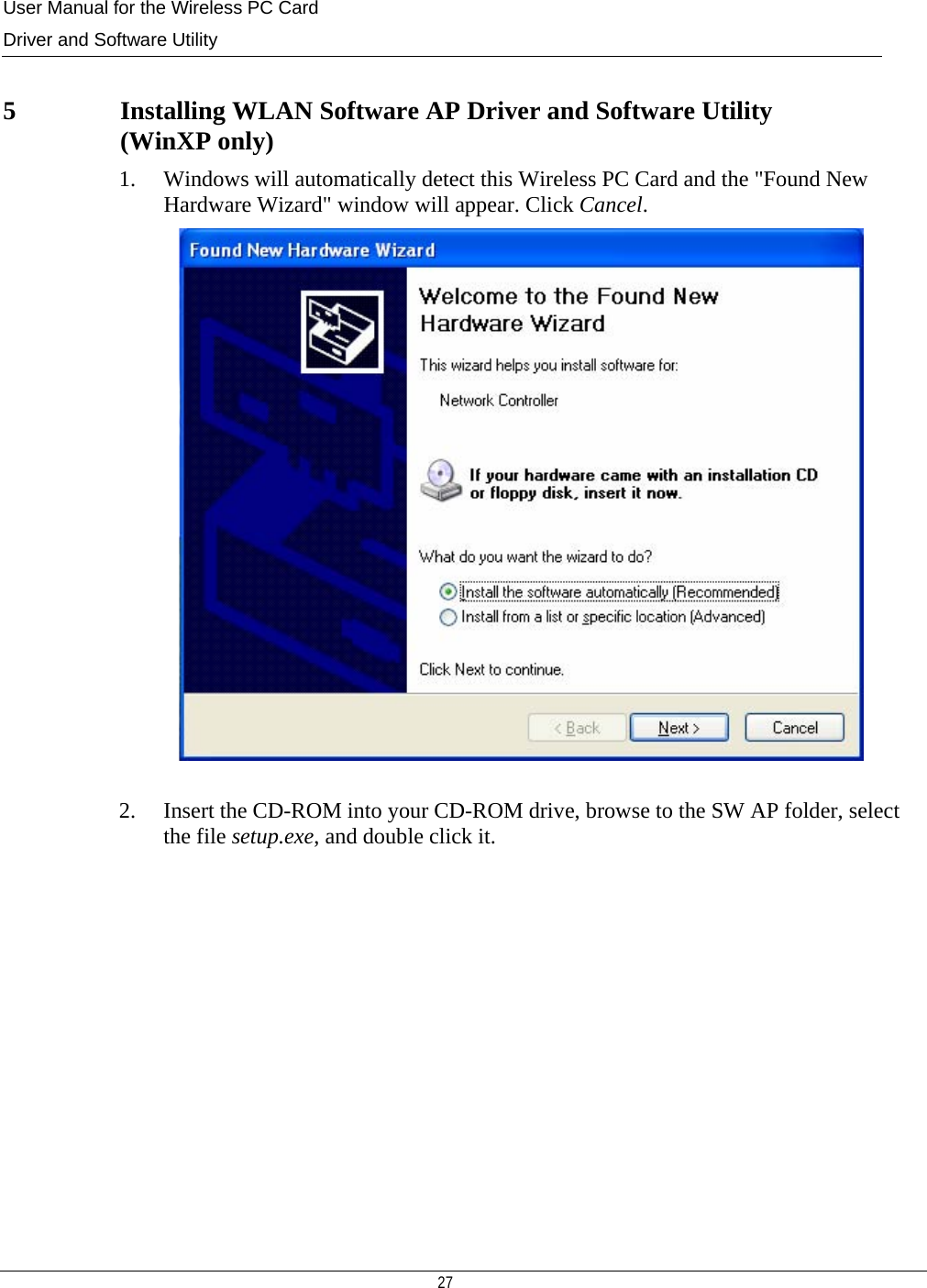
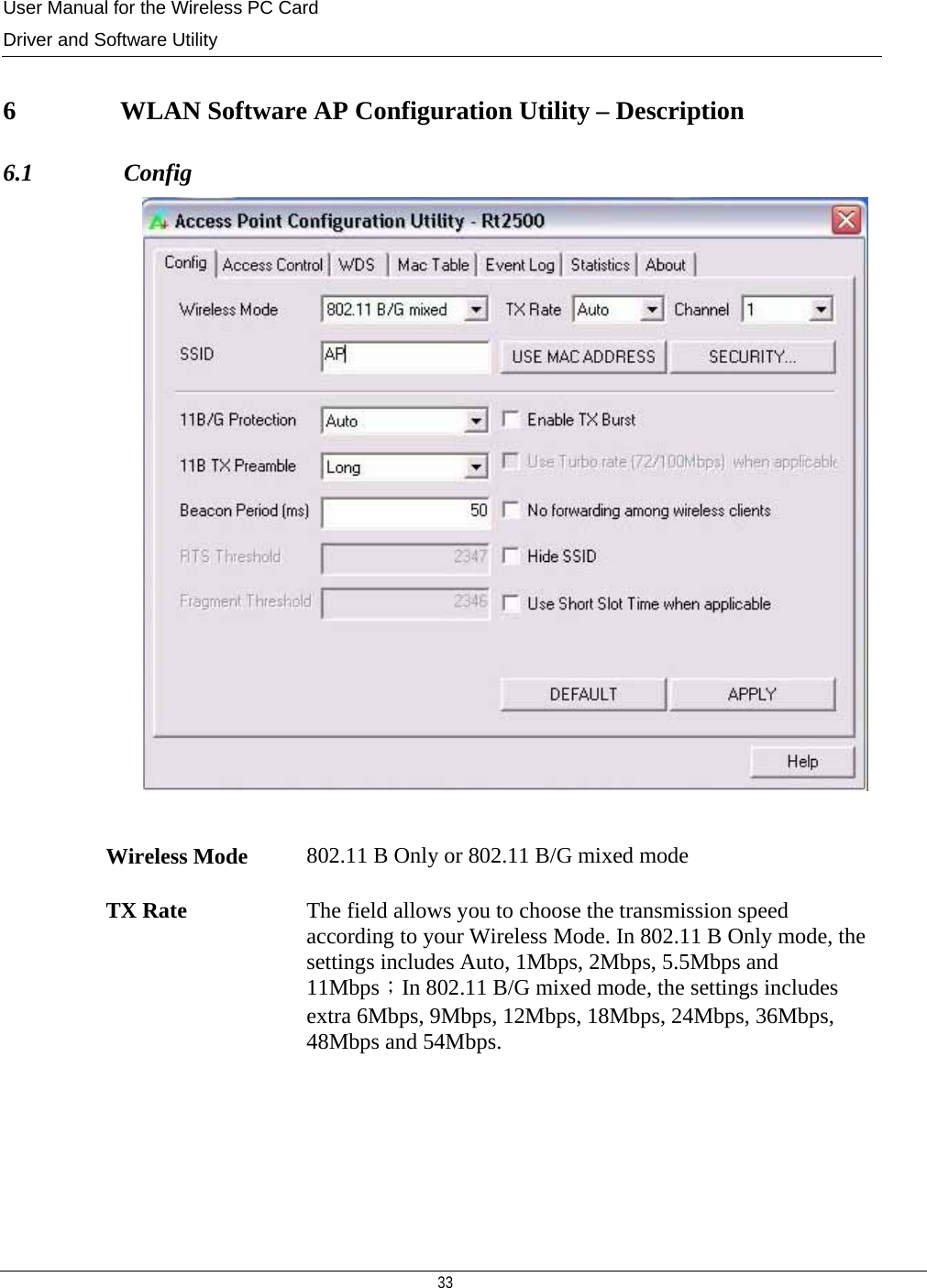
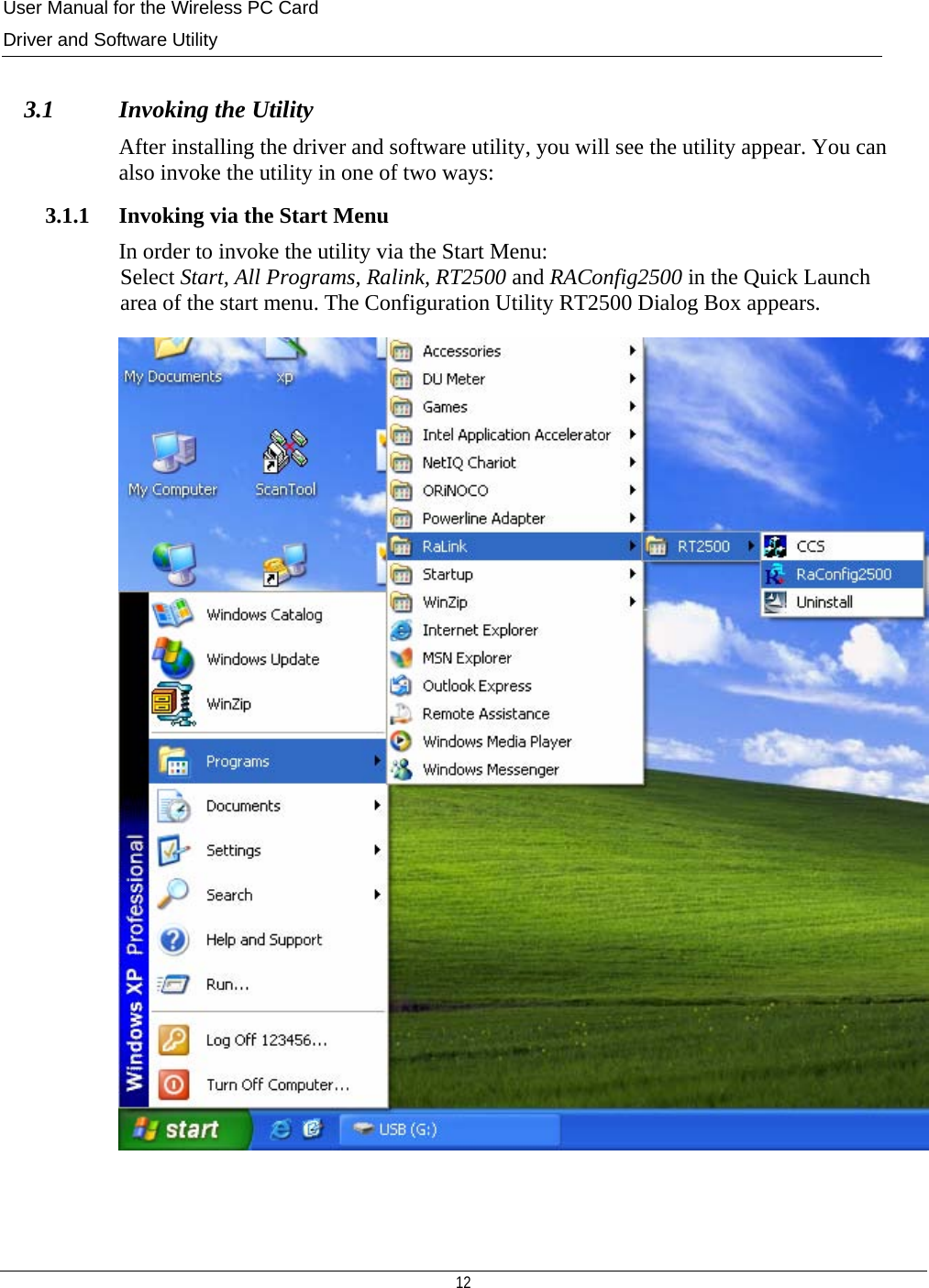
![User Manual for the Wireless PC Card Driver and Software Utility 34 Channel This is the radio channel through which the access point communicates to stations in its BSS. A Basic Service Set (BSS) consists of a group of wireless stations, and an access point that is directly connected to the wired LAN. To establish an Ad Hoc network, make sure the [Channel] is set to the same radio channel as that used by the other wireless clients in your group. However, if you are connecting to a network via an access point, the adapter will automatically synchronize up to the same channel as that used by the access point. Note: The available channel settings are limited to local regulations, which determine the number of channels that are available. FCC: 11 channels MKK: 14 channels SSID The character string of the wireless network identifier to which you want to connect. 11B/G Protection 802.11b uses CCK modulation and 802.11g uses CCK–compatible OFDM modulation. To prevent the data collision in the concurrent 802.11b and 802.11g network, it’s necessary to enable 11B/G Protection in 802.11 B/G mixed mode. 11B TX Preamble Long or Short preamble key type in the physical layer of packet Beacon Period (ms) Set a value here to define the duration between beacon packets.Enable TX Burst This field is to enable the Adapter to transmit more data in a frame interval, SIFS. Normally the frame interval is DIFS. Use Turbo rate (72/100Mbps) when applicable This field is disabled currently. No forwarding among wireless clients Click to prevent packet from looping among wireless clients. Hide SSID Do not show SSID in the public network. Use Short Slot Time when applicable This field enhances the maximum transmission power. DEFAULT Return to the default settings.](https://usermanual.wiki/Amigo-Technology/AWI-922W/User-Guide-484108-Page-35.png)