Amigo Technology BRC76N Wireless 2T2R Router User Manual 05 BRC76n Manual
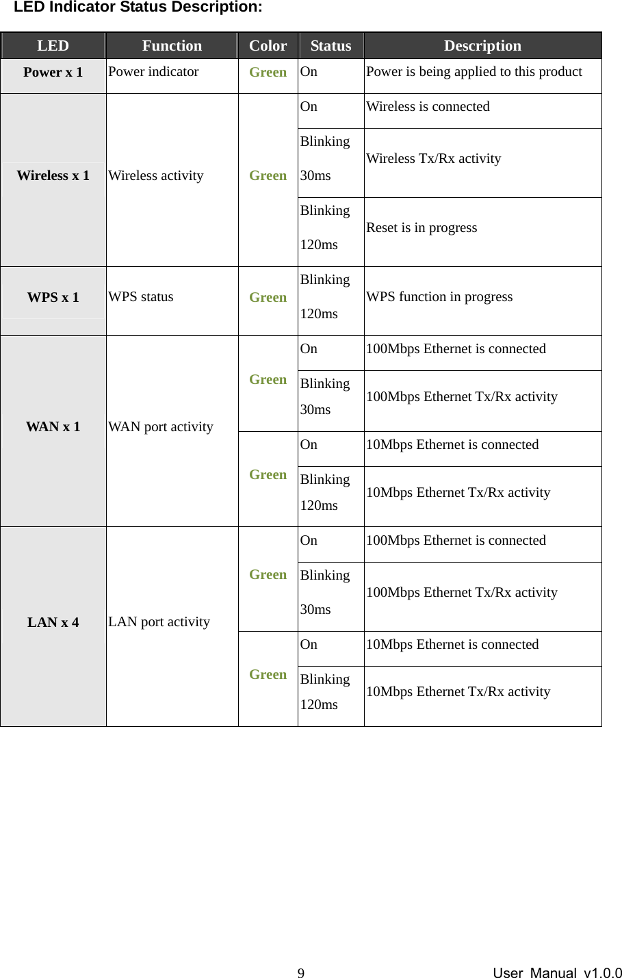
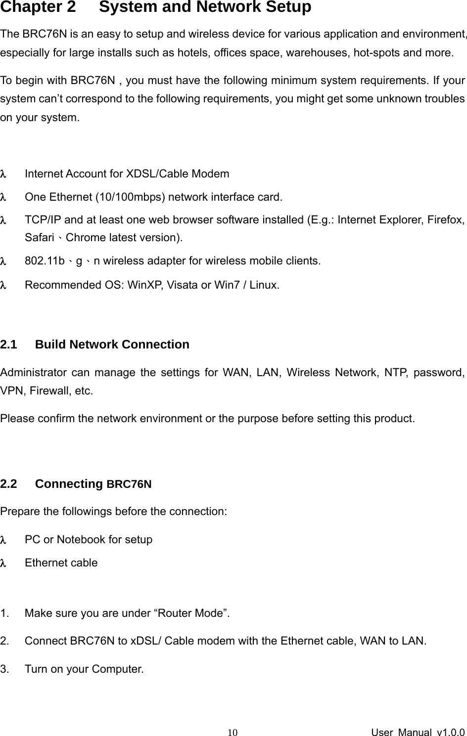
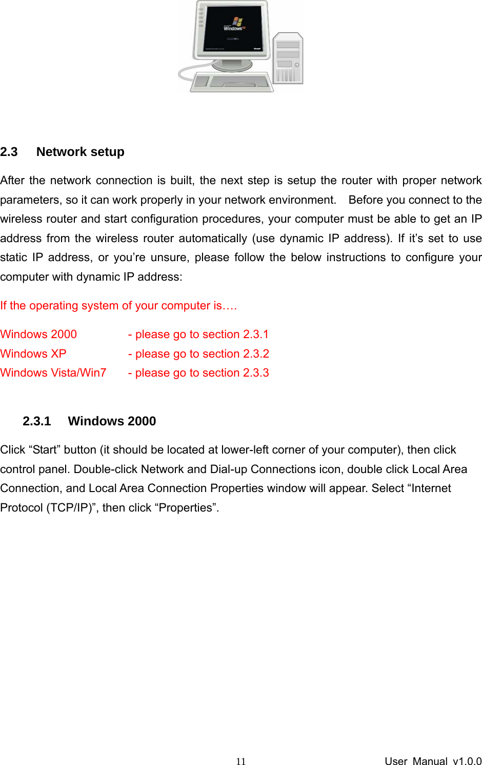
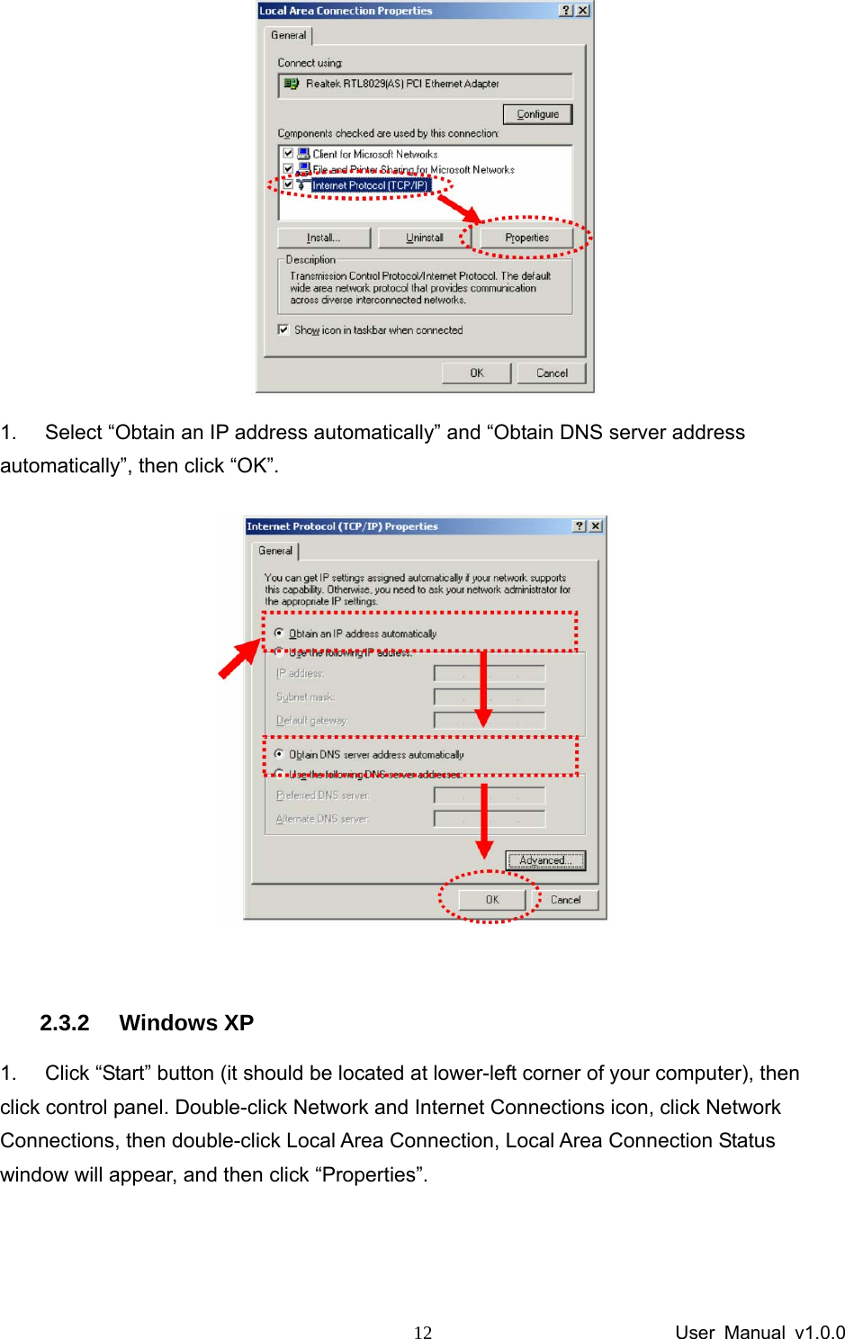
Amigo Technology Inc. Wireless 2T2R Router 05 BRC76n Manual
UserManual.wiki
>
Amigo Technology
>
BRC76N User Manual
user manual
Navigation menu
Upload a User Manual
Namespaces
Wiki Guide
HTML
PDF
Info
Views
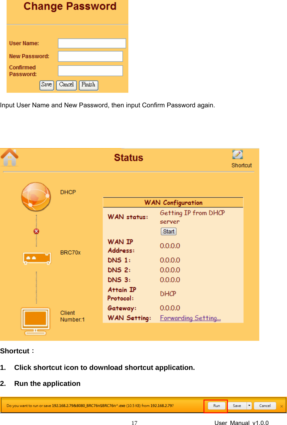
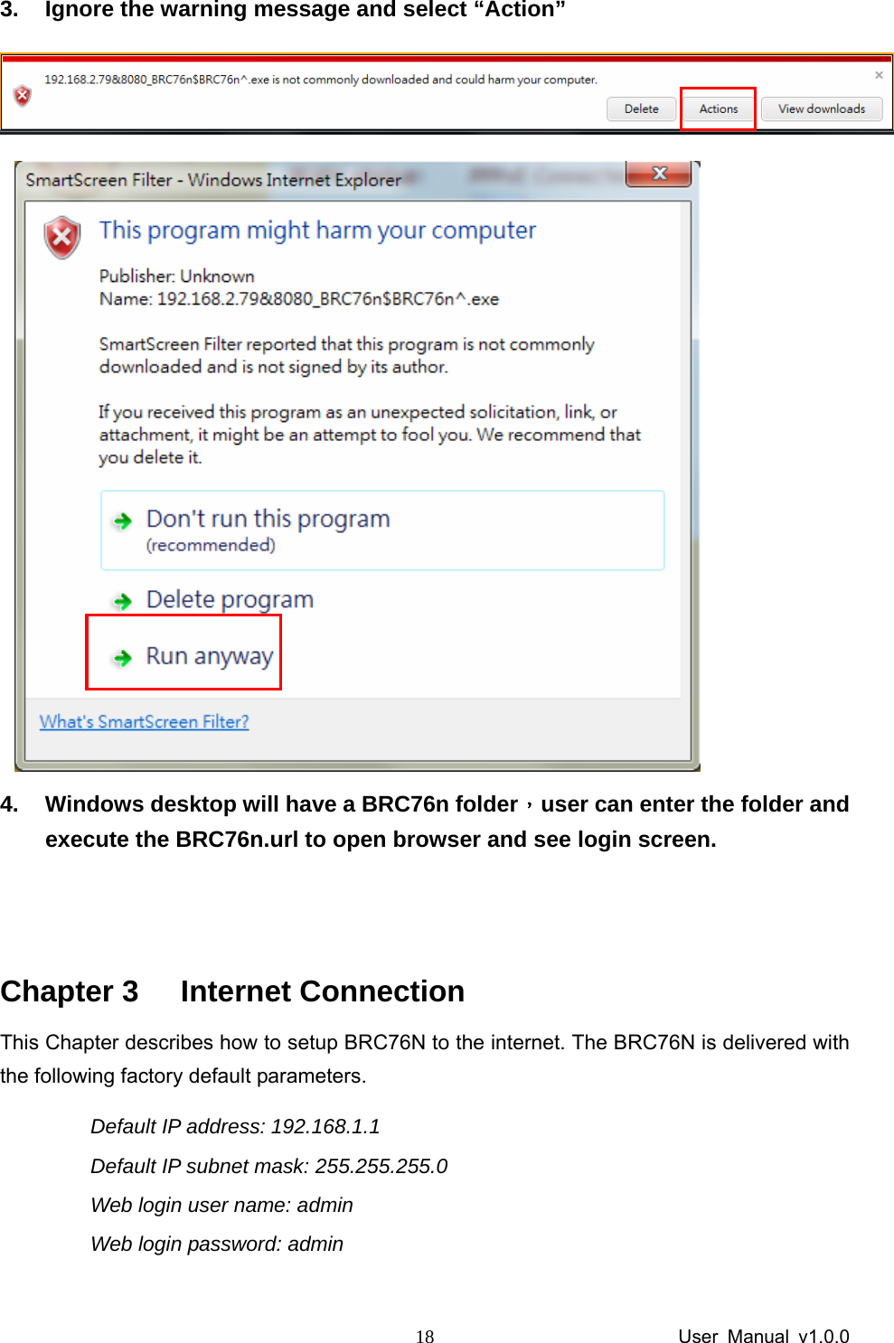
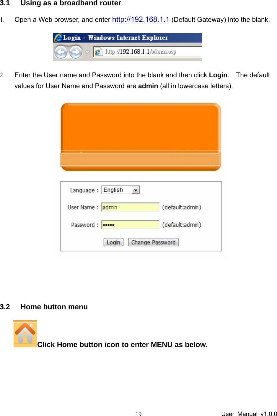
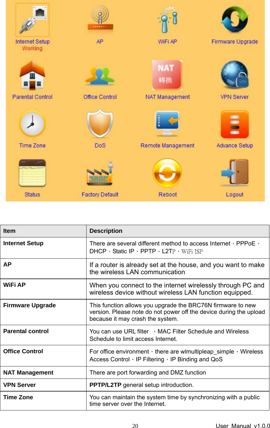
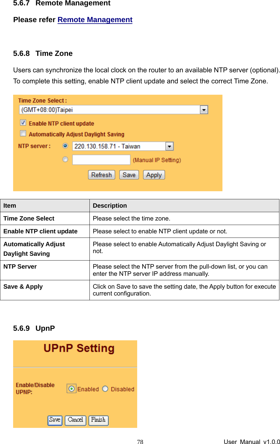
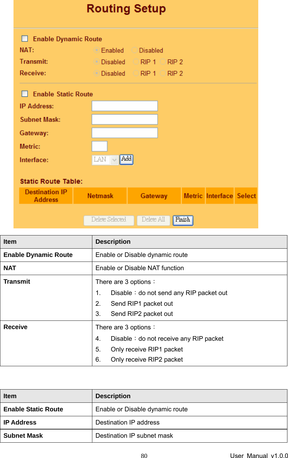
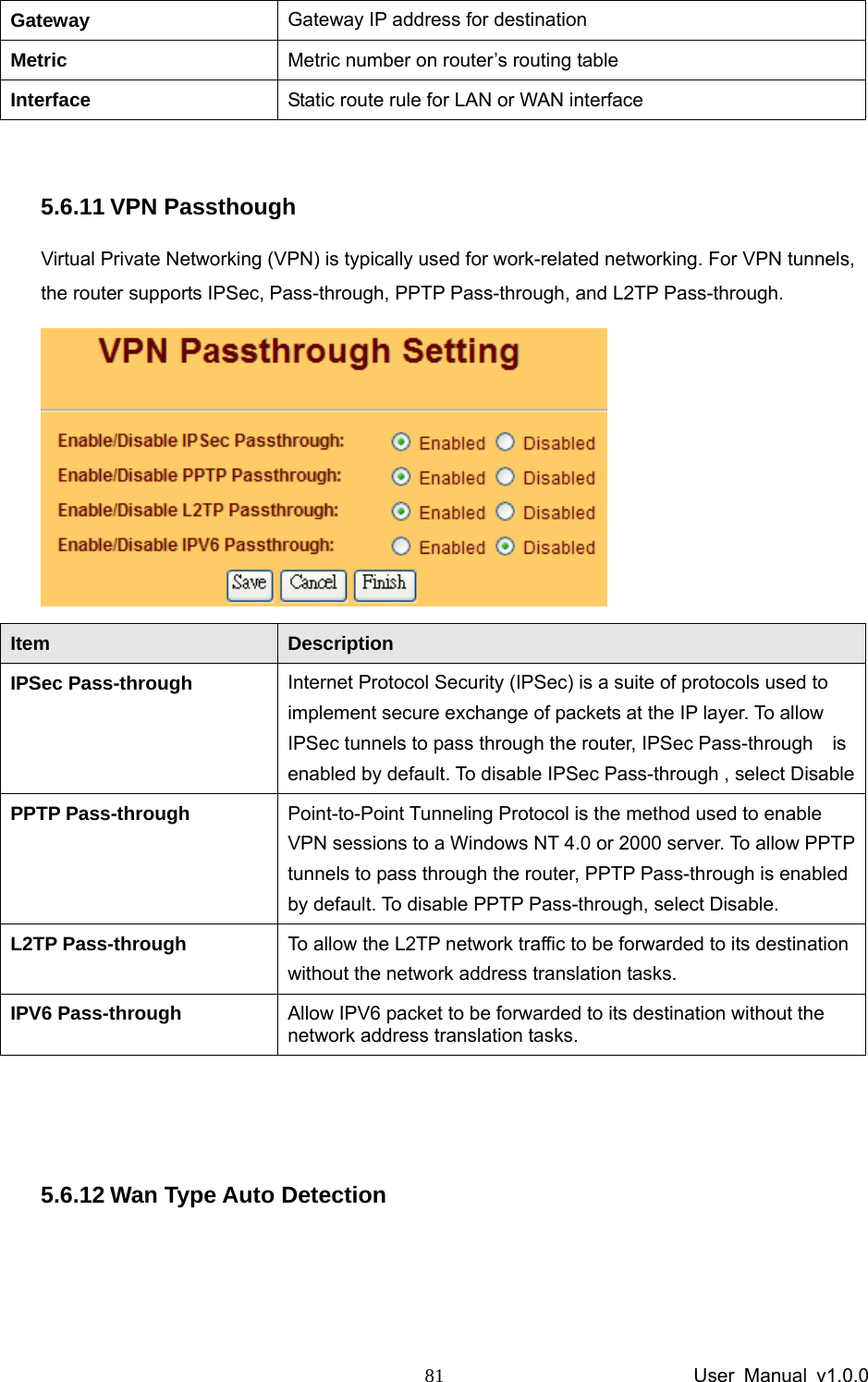
User Manual
Discussion / Help
Navigation