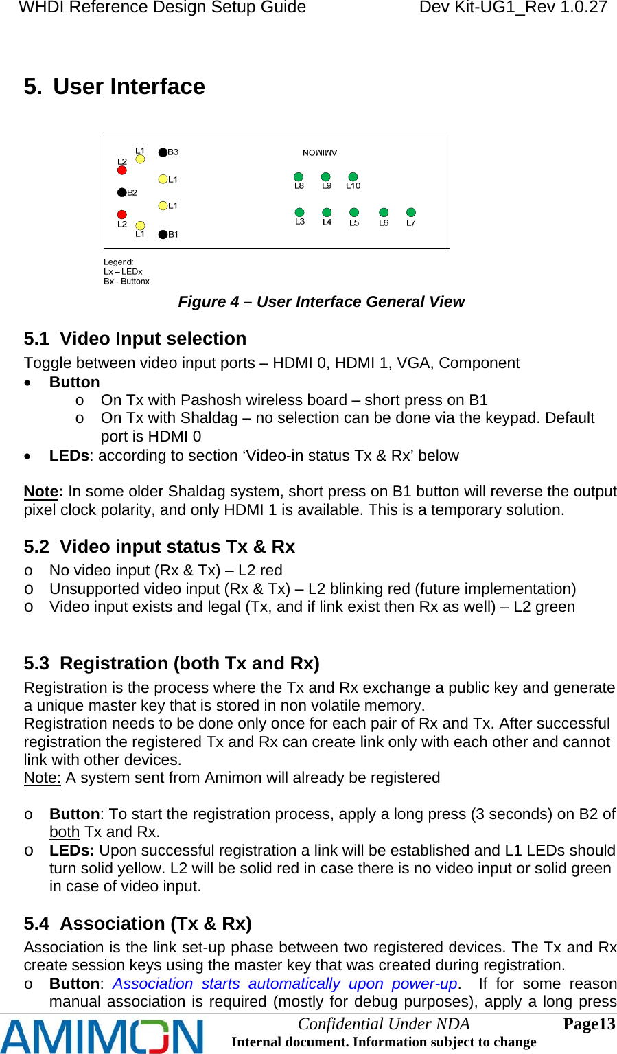
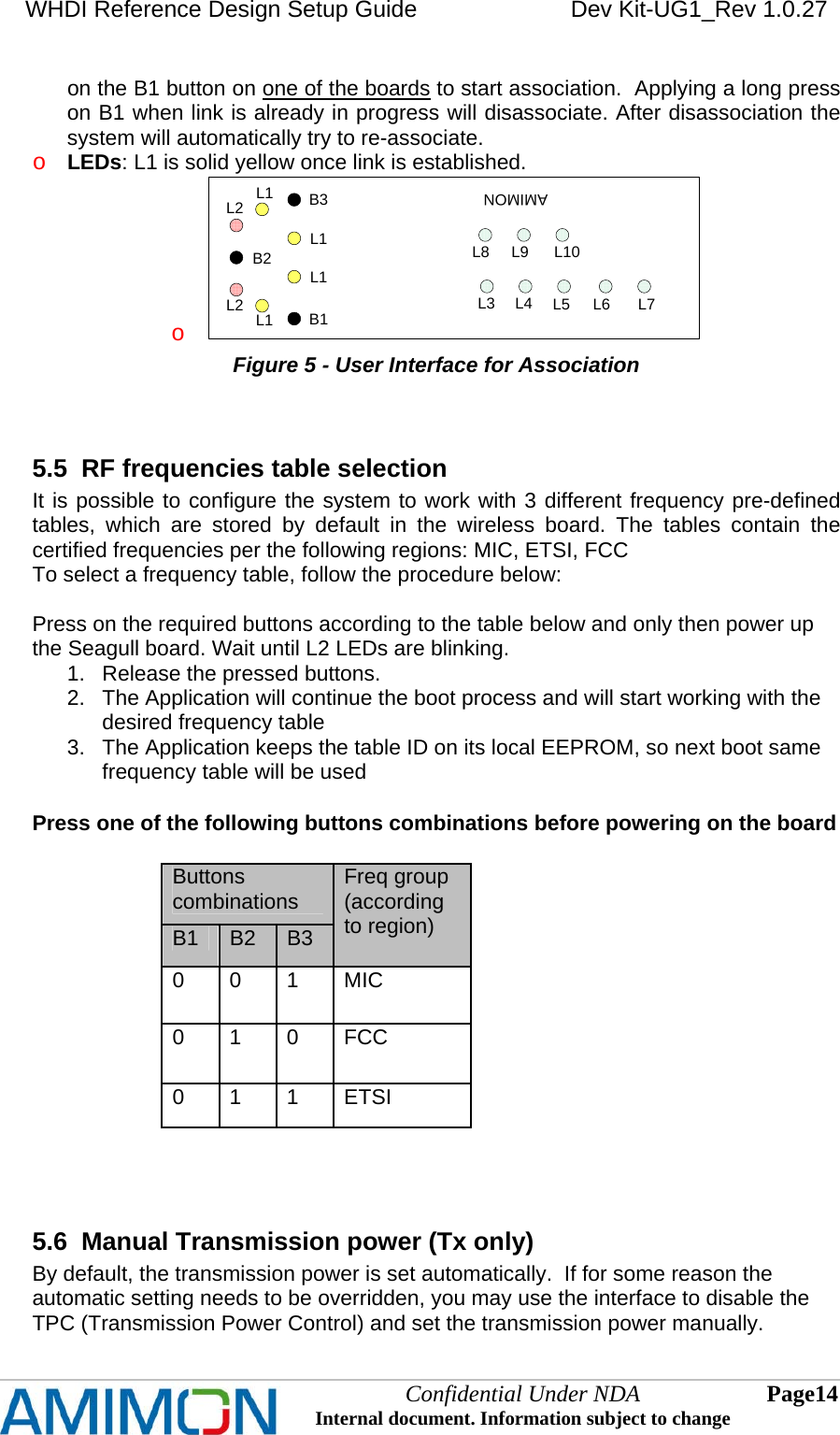
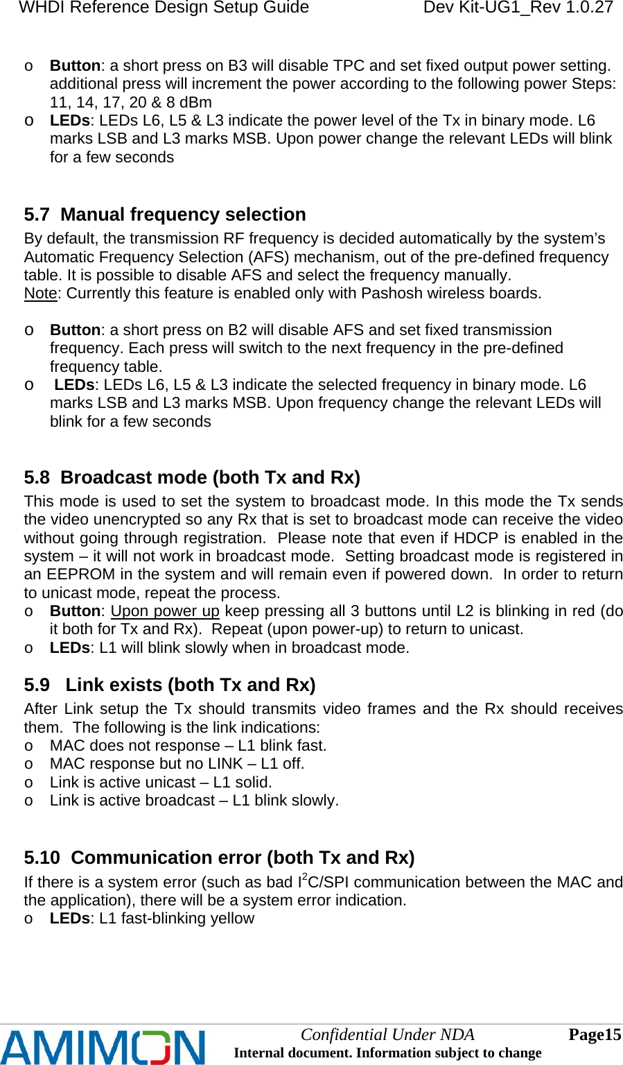
Amimon AMN32100 WHDI Video Destination Unit (VDU) User Manual

Amimon Ltd. WHDI Video Destination Unit (VDU)

Contents

User Manual

WHDI Reference Design Setup Guide   Dev Kit-UG1_Rev 1.0.27           Confidential Under NDA Internal document. Information subject to change  1 Page   UUUssseeerrr   MMMaaannnuuuaaalll
WHDI Reference Design Setup Guide   Dev Kit-UG1_Rev 1.0.27   Confidential Under NDA Internal document. Information subject to change  2 Page      IIImmmpppooorrrtttaaannnttt   NNNoootttiiiccceee      AMIMON Ltd. Reserves the right to make corrections, modifications, enhancements, improvements, and other changes to its products and services at any time and to discontinue any product or service without notice. Customers should obtain the latest relevant information before placing orders and should verify that such information is current and complete. All products are sold subject to AMIMON’s terms and conditions of sale supplied at the time of order acknowledgment. AMIMON warrants performance of its hardware products to the specifications applicable at the time of sale in accordance with AMIMON’s standard warranty. Testing and other quality control techniques are used to the extent AMIMON deems necessary to support this warranty. Except where mandated by government requirements, testing of all parameters of each product is not necessarily performed. AMIMON assumes no liability for applications assistance or customer product design. Customers are responsible for their products and applications using AMIMON components. To minimize the risks associated with customer products and applications, customers should provide adequate design and operating safeguards. AMIMON does not warrant or represent that any license, either express or implied, is granted under any AMIMON patent right, copyright, mask work right, or other AMIMON intellectual property right relating to any combination, machine, or process in which AMIMON products or services are used. Information published by AMIMON regarding third-party products or services does not constitute a license from AMIMON to use such products or services or a warranty or endorsement thereof. Use of such information may require a license from a third party under the patents or other intellectual property of the third party, or a license from AMIMON under the patents or other intellectual property of AMIMON. Reproduction of information in AMIMON data books or data sheets is permissible only if reproduction is without alteration and is accompanied by all associated warranties, conditions, limitations, and notices. Reproduction of this information with alteration is an unfair and deceptive business practice. AMIMON is not responsible or liable for such altered documentation. Resale of AMIMON products or services with statements different from or beyond the parameters stated by AMIMON for that product or service voids all express and any implied warranties for the associated AMIMON product or service and is an unfair and deceptive business practice. AMIMON is not responsible or liable for any such statements. All company and brand products and service names are trademarks or registered trademarks of their respective holders.
WHDI Reference Design Setup Guide   Dev Kit-UG1_Rev 1.0.27   Confidential Under NDA Internal document. Information subject to change  3 Page    Contact Us US Office 2350 Mission College Blvd. Suite 500 Santa Clara, CA 95054  Tel: +1 650 641 7178  Israeli Headquarters 2 Maskit St. Building D, 2nd Floor  P.O Box 12618 Herzlia 46733, Israel Tel: +972-9-962-9222 Fax: +972-9-956-5467 contact@AMIMON.com   AMIMON Japan K.K TK Gotanda Bldg 409, 5-10-18 Higashi-Gotanda, Shinagawa-ku, Tokyo, Japan 141-0022  Tel: 81-3-3444-4305  Fax: 81-3-3444-4351  contact.japan@amimon.com    Korea Office  706 DaerungPostTower2, 182-13, Guro-dong, Guro-gu, Seoul, Korea  Postal Code : 152-790 Office Tel : +82-2-569-9183 Fax : +82-2-569-9153 YH.Park@amimon.com    Taiwan Representative and Sales  Attn: Ruby Yen Tel: 886 9 18981219 ruby.yen@amimon.com   China representative and sales Attn: Richard Yuan 35-7-7B, Yang Guang Zong Lv Yuan, Qianhai Road, Nanshan District, Shenzhen 518048, Guangdong, China Tell: +86 13602584064 Fax: +86 755 86128798 richard.yuan@amimon.com
WHDI Reference Design Setup Guide   Dev Kit-UG1_Rev 1.0.27   Confidential Under NDA Internal document. Information subject to change  4 Page   RRReeevvviiisssiiiooonnn   HHHiiissstttooorrryyy   Version  Date  Description 0.8 25-Sep-07 Initial Release 0.10 17-Oct-07 Updated for SW version App-NXP_0_10: Rx LEDs follow Tx 0.0.19 04-Feb-08 Registration, association, TPC, AFS 0.0.20 13-May-08 Update new TPC 1.0.21 18-Sep-08 Changed from Canary to Pashosh Changed to new application code and new user interface 1.0.22 18-Nov-08 Updated UI to comply with App 1.3.5  1.0.23  Updated for Sparrow4 1.0.24 1-April-09 Roy Korin: updated for Seagull and (preliminary) for Shaldag 1.0.25  June 08 2009  Roy Korin: updated for application version 1.4.25 1.0.26  June 28 2009  Added comment about pixel clock in ‘Troubleshooting’ and section 5.1 1.0.27  Sept 21 2009  Updated back to normal Shaldag-Seagull version. Updated trouble shoot for wrong input port issue
WHDI Reference Design Setup Guide   Dev Kit-UG1_Rev 1.0.27   Confidential Under NDA Internal document. Information subject to change  5 Page    Certification & Compliance - FCC   This product is for indoor use only in the band of 5.15-5.25GHz.   This device complies with part 15 of the FCC Rules. Operation is subject to the following two conditions: (1) This device may not cause harmful interference, and (2) this device must accept any interference received, including interference that may cause undesired operation.   Any changes or modifications not expressly approved by Amimon for compliance could void the user's authority to operate the equipment.   This equipment has been tested and found to comply with the limits for a Class B digital device, pursuant to part 15 of the FCC Rules. These limits are designed to provide reasonable protection against harmful interference in a residential installation. This equipment generates, uses and can radiate radio frequency energy and, if not installed and used in accordance with the instructions, may cause harmful interference to radio communications. However, there is no guarantee that interference will not occur in a particular installation. If this equipment does cause harmful interference to radio or television reception, which can be determined by turning the equipment off and on, the user is encouraged to try to correct the interference by one or more of the following measures:   Reorient or relocate the receiving antenna.   Increase the separation between the equipment and receiver.   Connect the equipment into an outlet on a circuit different from that to which the receiver is connected.   Consult the dealer or an experienced radio/TV technician for help.  Caution: The module should be positioned so that personnel in the area for prolonged periods may safely remain at least 20 cm (8 in) in an uncontrolled environment from the module.
WHDI Reference Design Setup Guide   Dev Kit-UG1_Rev 1.0.27   Confidential Under NDA Internal document. Information subject to change  6 Page   TTTaaabbbllleee   ooofff   CCCooonnnttteeennntttsss   1. PURPOSE 7 2. THE SYSTEM 8 2.1 TX SIDE 8 2.1.1 Wireless Tx board 8 2.1.2 Seagull Interface Tx Board 8 2.1.3 User Interface board (AMN060) 9 2.2 RX SIDE 9 2.2.1 Wireless Rx Board 9 2.2.2 Seagull Rx Interface Board 10 2.2.3 User Interface board (AMN60) 10 3. SETTING-UP A LINK 11 3.1 ENABLING COMMUNICATION TO THE WIRELESS MODULE 11 3.2 BASIC LINK SET-UP 11 4. SYSTEM CONFIGURATION 12 4.1 SUPPORTED RESOLUTIONS 12 4.2 HDMI 12 5. USER INTERFACE 13 5.1 VIDEO INPUT SELECTION 13 5.2 VIDEO INPUT STATUS TX & RX 13 5.3 REGISTRATION (BOTH TX AND RX) 13 5.4 ASSOCIATION (TX & RX) 13 5.5 RF FREQUENCIES TABLE SELECTION 14 5.6 MANUAL TRANSMISSION POWER (TX ONLY) 14 5.7 MANUAL FREQUENCY SELECTION 15 5.8 BROADCAST MODE (BOTH TX AND RX) 15 5.9 LINK EXISTS (BOTH TX AND RX) 15 5.10 COMMUNICATION ERROR (BOTH TX AND RX) 15 5.11 DVI MODE (RX ONLY) 16 6. BASIC TROUBLESHOOTING 17  LLLiiisssttt   ooofff   FFFiiiggguuurrreeesss   Figure 1 – wireless modules connectors  9 Figure 2 - User Interface Board  9 Figure 3  – SW6  11 Figure 4 – User Interface General View  13 Figure 5 - User Interface for Association  14 Figure 6 - LEDs for System Error Indication  16
WHDI Reference Design Setup Guide   Dev Kit-UG1_Rev 1.0.27   Confidential Under NDA Internal document. Information subject to change  7 Page   1.  Purpose This document explains the required steps needed for setting up a link with AMIMON's WHDITM Development Platform.  This is a basic user's guide that includes troubleshooting and a description of the basic features of the system that should allow the user to establish a video link and control the system  This document refers to systems running Pashosh with MAC version 1.5.35/1.3.35 and on, Shaldag with MAC version 3.0 and on, with application (Seagull) version 1.4.25 and on.
WHDI Reference Design Setup Guide   Dev Kit-UG1_Rev 1.0.27   Confidential Under NDA Internal document. Information subject to change  8 Page   2.  The System  The system consists of a Tx part and an Rx part.  Each of the parts is comprised of a box, a 5V 2A DC power supply and 3 main board components:   A wireless board, that contains the antennas, the RF components and the Baseband (BB) chip. The wireless board can be one of the following: o Canary (AMN1110/AMN1210) – First generation board, based on Amimon 1st generation BB and Maxim RF transceivers o Pashosh (AMN11310/AMN12310) – Second generation board, based on Amimon 1st generation BB and Amimon single-chip RFIC o Shaldag – Third generation board, based on Amimon 2st generation BB and Amimon single-chip RFIC   An interface (also called ‘application’ or ‘I/O’) board which is the audio-video input/output board. The interface board is called Seagull, and is numbered AMN_PCB_117/118   A User-Interface board that has LEDs and buttons. (AMN60)  Note: The functionality and operation described in this document is identical to all three possible wireless boards, unless specifically noted  2.1  Tx side 2.1.1  Wireless Tx board The Canary/Pashosh/Shaldag wireless Tx board is the transmission part of AMIMON's wireless system.  The board has 5 printed antennas, 4 of which are for transmission and 1 is for reception of the back-channel. In addition there is one uplink reception diversity antenna. The board also contains the RF components, the Baseband Tx chip and the MAC microprocessor. On the Shaldag board the MAC microprocessor is embedded inside the BB chip. It is connected to the Seagull interface board through a WHDI connector.  The wireless board receives its power supply from the Seagull interface board through the WHDI connector.  2.1.2  Seagull Interface Tx Board The Seagull Interface Tx board is used to connect from the various sources to the wireless link.  It contains the following video and audio inputs:    2 HDMI inputs   VGA input (optional)  Stereo I2S audio (optional)   Optical SPDIF audio input (optional)  Seagull board supports the following Amimon’s wireless module (see fig 1.a): -  Canary   (via J12)  -  Pashosh (via J12) -  Shaldag  (via J15)
WHDI Reference Design Setup Guide   Dev Kit-UG1_Rev 1.0.27                                                                  Figure 1 – wireless modules connectors   -  The board also contains a remote control IR receiver port (optional) that will be supported with later SW versions.  -  The power supply of the Seagull board is 5V 2A center positive DC power.  2.1.3  User Interface board (AMN060) The AMN060 User Interface (UI) board is used to perform several operations, such as registration, display link status etc. Figure 2 shows the picture of the Interface board, that later on in this document will be illustrated as a schematic drawing for clarity.  Please refer to chapter 5 for a description of the various LEDs and buttons use and indications.    Figure 2 - User Interface Board  2.2  Rx side 2.2.1  Wireless Rx Board The Canary/Pashosh/Shaldag Wireless Rx board is the reception part of AMIMON's system.  The board has 5 printed antennas, 4 of which are for reception and 1 alternates between reception and transmission of the back-channel (uplink). The board also contains the RF components, the Baseband Rx chip and the MAC microprocessor. On the Shaldag board the MAC microprocessor is embedded inside the BB chip. It is connected to the Seagull interface board through a WHDI connector.  The wireless board gets its 5V power supply from the Seagull interface board through the WHDI connector.  Confidential Under NDA Internal document. Information subject to change  9 Page
WHDI Reference Design Setup Guide   Dev Kit-UG1_Rev 1.0.27   Confidential Under NDA Internal document. Information subject to change  10 Page   Note: To ensure optimal performance please make sure that the antennas are not blocked by any object, both on Tx and Rx sides  2.2.2  Seagull Rx Interface Board The Seagull Rx Interface board is used to interface to the various displays and destinations of the wireless link.  It contains the following video and audio outputs:   HDMI output  Stereo I2S audio (optional)   Optical SPDIF audio input (optional)  Seagull board is supporting the following Amimon’s wireless modules (same as fig                1.a): -  Canary   (via J12) -  Pashosh (via J12) -  Shaldag  (via J15)  -  The board also contains a remote control IR receiver port (optional) that will be supported with later SW versions.  -  The power supply of the Sparrow board is 5V 2A center positive DC power.  2.2.3  User Interface board (AMN60)  See section 2.1.3 above
WHDI Reference Design Setup Guide   Dev Kit-UG1_Rev 1.0.27   3.  Setting-up a Link 3.1  Enabling communication to the wireless module Seagull boards can work with Canary, Pashosh and Shaldag application boards. Canary and Pashosh use I2C protocol with the Seagull board, while Shaldag uses SPI protocol. The Seagull boards contain Dip Switch to select I2C/SPI communication. In case using Pashosh/Canary, dip switch 1 should be set to ‘On’ (as the figure below). In case using Shaldag dip switch should be off.                                                         Figure 3  – SW6   3.2  Basic Link Set-Up To create a link, follow the below procedure:   Connect the Tx module to a video source using an HDMI cable. Use HDMI 0 port by default (this is Shaldag based system default)   Connect the Rx module to a display (monitor/TV/projector) using an HDMI cable.   Connect the power supplies to both Tx and Rx modules. Ensure that the power switches are off.   Power on the Tx using the power switch and wait for the status LEDs (L2) to turn on. They should be red if no source is connected and turn green if a legal source is connected and the video resolution is identified.  Refer to section 5.5 for more information.   In case the source is off, turn it on and make sure it is set to output a legal resolution (refer to section 4.1). The status LEDs (L2) on the Tx should turn to green once the source was recognized and the transmission is set and (refer to section 5.5).   Make sure your display is on and set to the right input source.   Power on the Rx using the power switch. L1 yellow LEDs should turn on once association is completed and the link is connected (refer to section 5.5). Link establishment process may take 10-15 seconds.   Once link is established, RX L2 LEDs should turn green, and there should be audio and video reception on the display.   In case the display has only a DVI port and the Rx can be connected to a display via an HDMI to DVI cable.  Refer to section 5.7 for explanation on setting DVI mode.  Confidential Under NDA Internal document. Information subject to change  11 Page
WHDI Reference Design Setup Guide   Dev Kit-UG1_Rev 1.0.27   Confidential Under NDA Internal document. Information subject to change  12 Page   4.  System Configuration 4.1 Supported resolutions The Sparrow system currently supports video formats up to and including:  720p 60fps  1080i 60fps  1080p 24fps/30fps   1080p 60fps (Shaldag system)  The system is configured to automatically recognize the resolution, and adjust accordingly.  Switching sources and resolutions once the link is set is legal, and the system should adjust automatically, although this may result in a few frames of blank video and may take a few seconds. The system is also capable of recognizing the color space (RGB/YCbCr) and adjusting accordingly.  4.2 HDMI To ensure full support and optimal performance, the HDMI (or DVI) source and display connected to the WHDI Reference Design system should support EDID and HDCP, and should provide the necessary 5V DC voltage as specified by the HDMI requirements.
WHDI Reference Design Setup Guide   Dev Kit-UG1_Rev 1.0.27   5.  User Interface  Figure 4 – User Interface General View 5.1  Video Input selection Toggle between video input ports – HDMI 0, HDMI 1, VGA, Component  Button o  On Tx with Pashosh wireless board – short press on B1 o  On Tx with Shaldag – no selection can be done via the keypad. Default port is HDMI 0  LEDs: according to section ‘Video-in status Tx & Rx’ below  Note: In some older Shaldag system, short press on B1 button will reverse the output pixel clock polarity, and only HDMI 1 is available. This is a temporary solution. 5.2  Video input status Tx & Rx o  No video input (Rx & Tx) – L2 red o Unsupported video input (Rx & Tx) – L2 blinking red (future implementation) o Video input exists and legal (Tx, and if link exist then Rx as well) – L2 green  5.3  Registration (both Tx and Rx) Registration is the process where the Tx and Rx exchange a public key and generate a unique master key that is stored in non volatile memory.   Registration needs to be done only once for each pair of Rx and Tx. After successful registration the registered Tx and Rx can create link only with each other and cannot link with other devices. Note: A system sent from Amimon will already be registered  o Button: To start the registration process, apply a long press (3 seconds) on B2 of both Tx and Rx. o LEDs: Upon successful registration a link will be established and L1 LEDs should turn solid yellow. L2 will be solid red in case there is no video input or solid green in case of video input. 5.4  Association (Tx & Rx) Association is the link set-up phase between two registered devices. The Tx and Rx create session keys using the master key that was created during registration. o Button:  Association starts automatically upon power-up.  If for some reason manual association is required (mostly for debug purposes), apply a long press Confidential Under NDA Internal document. Information subject to change  13 Page
WHDI Reference Design Setup Guide   Dev Kit-UG1_Rev 1.0.27   on the B1 button on one of the boards to start association.  Applying a long press on B1 when link is already in progress will disassociate. After disassociation the system will automatically try to re-associate. o LEDs: L1 is solid yellow once link is established.  o AMIMONB1B2B3L1L1L1L1L2L2L3 L4 L5 L6 L7L8 L9 L10 Figure 5 - User Interface for Association  5.5  RF frequencies table selection It is possible to configure the system to work with 3 different frequency pre-defined tables, which are stored by default in the wireless board. The tables contain the certified frequencies per the following regions: MIC, ETSI, FCC To select a frequency table, follow the procedure below:  Press on the required buttons according to the table below and only then power up the Seagull board. Wait until L2 LEDs are blinking.  1.  Release the pressed buttons. 2.  The Application will continue the boot process and will start working with the desired frequency table 3.  The Application keeps the table ID on its local EEPROM, so next boot same frequency table will be used  Press one of the following buttons combinations before powering on the board  Buttons combinations B1  B2  B3 Freq group (according to region) 0 0 1 MIC 0 1 0 FCC 0 1 1 ETSI   5.6  Manual Transmission power (Tx only)  By default, the transmission power is set automatically.  If for some reason the automatic setting needs to be overridden, you may use the interface to disable the TPC (Transmission Power Control) and set the transmission power manually. Confidential Under NDA Internal document. Information subject to change  14 Page
WHDI Reference Design Setup Guide   Dev Kit-UG1_Rev 1.0.27   Confidential Under NDA Internal document. Information subject to change  15 Page   o Button: a short press on B3 will disable TPC and set fixed output power setting. additional press will increment the power according to the following power Steps: 11, 14, 17, 20 & 8 dBm o LEDs: LEDs L6, L5 & L3 indicate the power level of the Tx in binary mode. L6 marks LSB and L3 marks MSB. Upon power change the relevant LEDs will blink for a few seconds  5.7  Manual frequency selection By default, the transmission RF frequency is decided automatically by the system’s Automatic Frequency Selection (AFS) mechanism, out of the pre-defined frequency table. It is possible to disable AFS and select the frequency manually. Note: Currently this feature is enabled only with Pashosh wireless boards.  o Button: a short press on B2 will disable AFS and set fixed transmission frequency. Each press will switch to the next frequency in the pre-defined frequency table. o  LEDs: LEDs L6, L5 & L3 indicate the selected frequency in binary mode. L6 marks LSB and L3 marks MSB. Upon frequency change the relevant LEDs will blink for a few seconds  5.8  Broadcast mode (both Tx and Rx) This mode is used to set the system to broadcast mode. In this mode the Tx sends the video unencrypted so any Rx that is set to broadcast mode can receive the video without going through registration.  Please note that even if HDCP is enabled in the system – it will not work in broadcast mode.  Setting broadcast mode is registered in an EEPROM in the system and will remain even if powered down.  In order to return to unicast mode, repeat the process. o Button: Upon power up keep pressing all 3 buttons until L2 is blinking in red (do it both for Tx and Rx).  Repeat (upon power-up) to return to unicast. o LEDs: L1 will blink slowly when in broadcast mode. 5.9   Link exists (both Tx and Rx) After Link setup the Tx should transmits video frames and the Rx should receives them.  The following is the link indications: o  MAC does not response – L1 blink fast. o  MAC response but no LINK – L1 off. o  Link is active unicast – L1 solid. o  Link is active broadcast – L1 blink slowly.  5.10  Communication error (both Tx and Rx) If there is a system error (such as bad I2C/SPI communication between the MAC and the application), there will be a system error indication. o LEDs: L1 fast-blinking yellow
WHDI Reference Design Setup Guide   Dev Kit-UG1_Rev 1.0.27   AMIMONB1B2B3L1L1L1L1L2L2L3 L4 L5 L6 L7L8 L9 L10 Figure 6 - LEDs for System Error Indication 5.11  DVI mode (Rx Only) In case the display has only a DVI port and the Rx is connected to a display via an HDMI to DVI cable, you should set the Rx in DVI mode which removes the audio from the link.  This mode can also be used to mute an HDMI link. o Button: A short press on B3 sets the Rx in DVI mode (default mode is HDMI). An additional press returns the Rx to HDMI mode.     Confidential Under NDA Internal document. Information subject to change  16 Page
WHDI Reference Design Setup Guide   Dev Kit-UG1_Rev 1.0.27   Confidential Under NDA Internal document. Information subject to change  17 Page   6.  Basic Troubleshooting  Before proceeding to the common troubleshooting procedures below make sure that Tx, Rx, source and display are powered, connected and on. Then proceed:  Issue:  No video:    Check the status of the Link LEDs: LEDs off  Make sure the power is connected and devices are on Tx L2 red  Make sure the source is on, connected to the HDMI port and outputting a legal resolution. Try to switch the input to the other HDMI port. Connecting a valid video to the right HDMI port should switch the LEDs from green to red. Rx L2 red  Make sure the Tx is transmitting (L2 on Tx is green), and check if the devices were pre-registered. Make sure that if L2 is green on the Tx, it turns red when pulling out the HDMI cable.  If not – the input selected is probably component or VGA. Switch to HDMI by applying a short presses on B1 until HDMI port is selected. Tx or Rx L1 (Yellow LEDs) blinking fast Hardware issue: check connection between wireless and interface boards. Check the correct state of dip switch 1 Rx L2 green, but no image on screen Make sure the display is connected, on and set on the right channel/source Tx and/or Rx L1 blinking slow   One or more of the link sides are in broadcast mode.  If only one of them is in broadcast mode a link will not be established.  Either set both to broadcast mode or both to unicast mode   If both are in broadcast mode intentionally, make sure your source in not an HDCP source.  Broadcast mode does not support HDCP content. Bad Picture    Make sure the HDMI cables used are intact and that you get a good picture by connecting the source directly to the display by an HDMI cable (bypassing the WHDI link).    Make sure nothing is touching or blocking the antennas   Try restarting the link ‘Dot noise’ around color transitions  In Shaldag only – Randomly the system may power on with reversed polarity of the pixel clock output. Apply a short press to B1 on the Seagull Tx keypad board Bad Audio/No Audio   Make sure the volume on the receiver is on   Make sure that the source is outputting legal audio formats (the system currently does not support HD audio)   Make sure you are not in DVI mode and you are not using DVI cables anywhere in the link   If there are mutes during the link, try restarting the link   Make sure there are no wireless phones in the area that use the 5.8 GHz band, as some of the phones on the market use sub-standard transmission schemes. Other Issues / Unresolved Issues If any other issue occurs of if the above issues persist, try powering off both Rx and Tx and repeating the link set-up process
WHDI Reference Design Setup Guide   Dev Kit-UG1_Rev 1.0.27   Confidential Under NDA Internal document. Information subject to change  18 Page

Navigation menu