Amimon AMNBZT1 Connex TX User Manual CONNEX User Guide
Amimon Ltd. Connex TX CONNEX User Guide
UserManual.wiki
>
Amimon
>
AMNBZT1 User Manual
User Guide
Navigation menu
Upload a User Manual
Namespaces
Wiki Guide
HTML
PDF
Info
Views
User Manual
Discussion / Help
Navigation
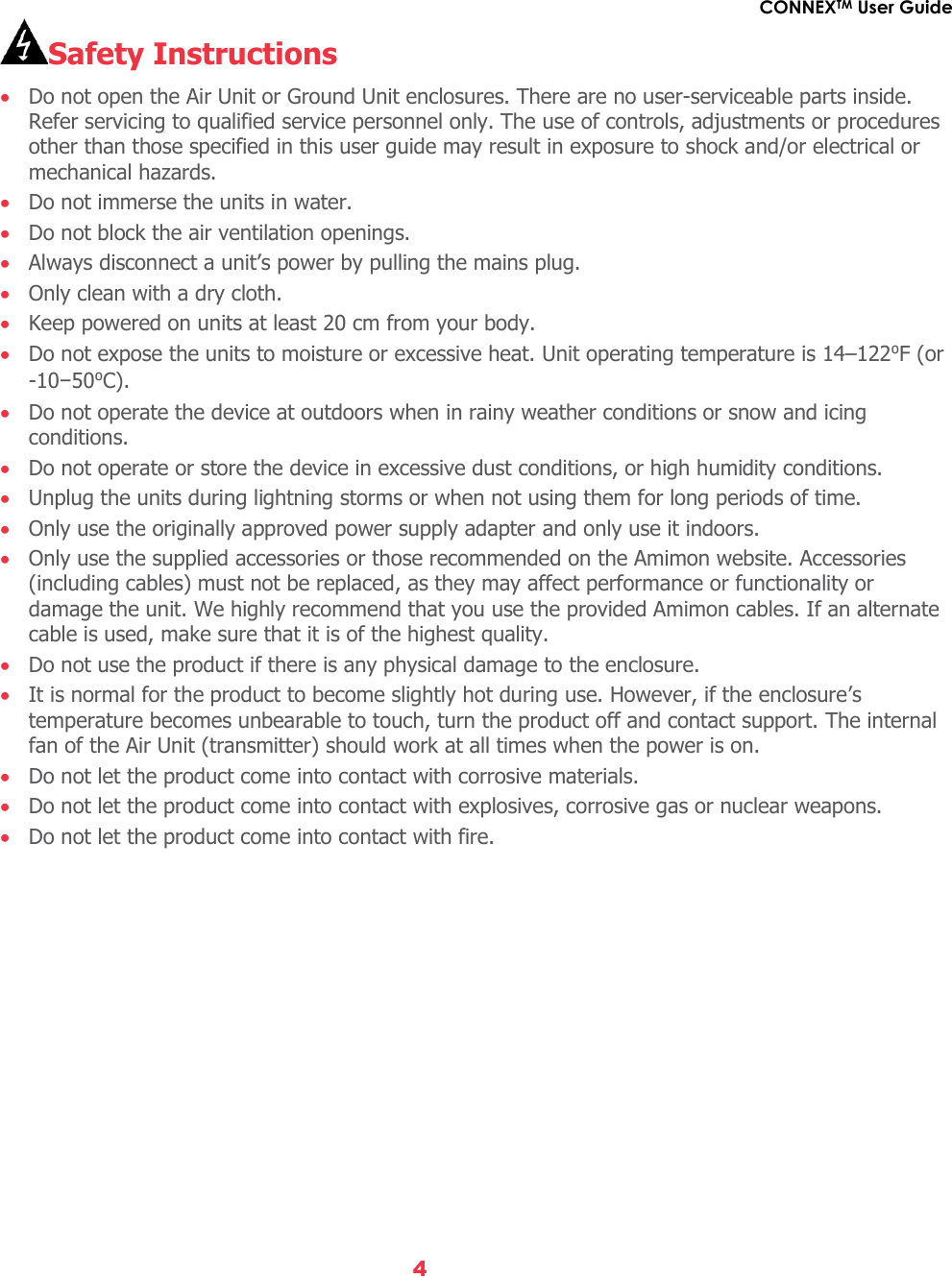

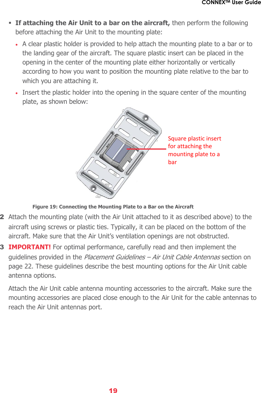
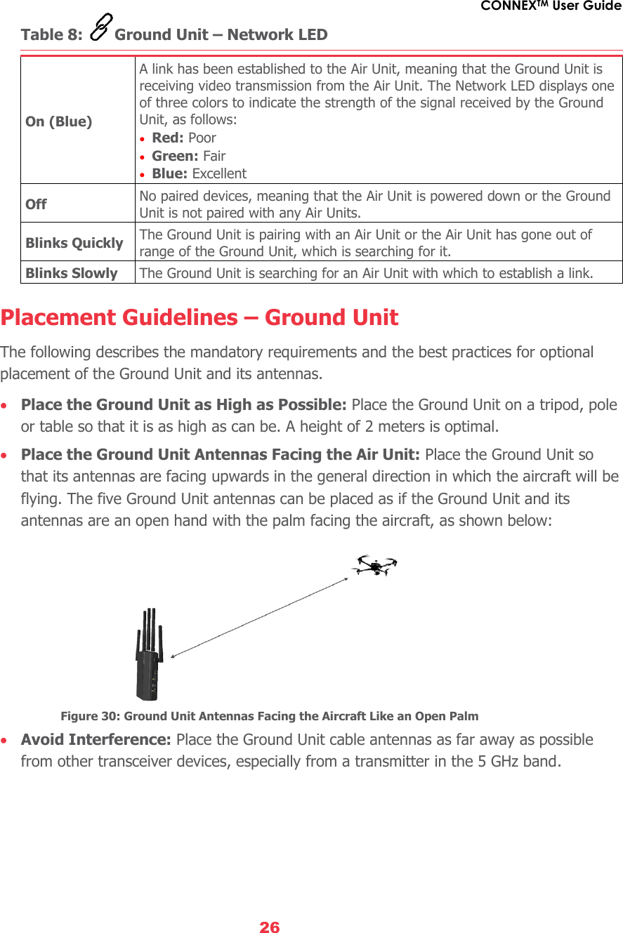
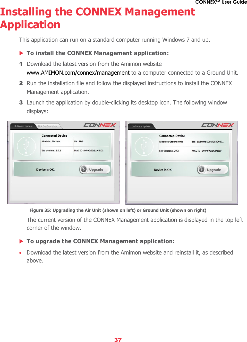
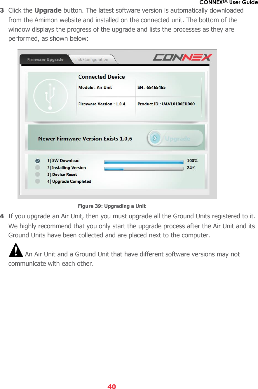
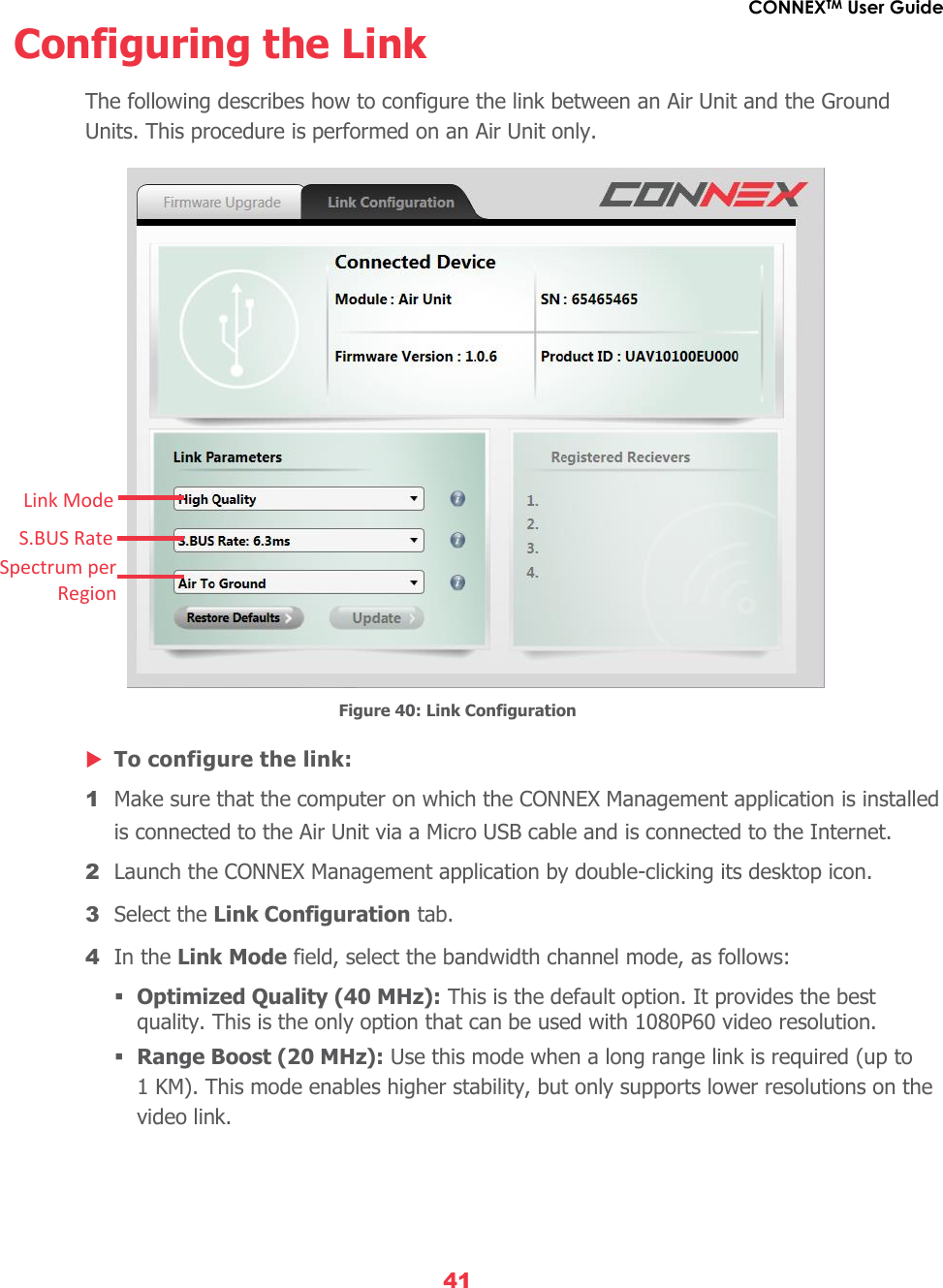
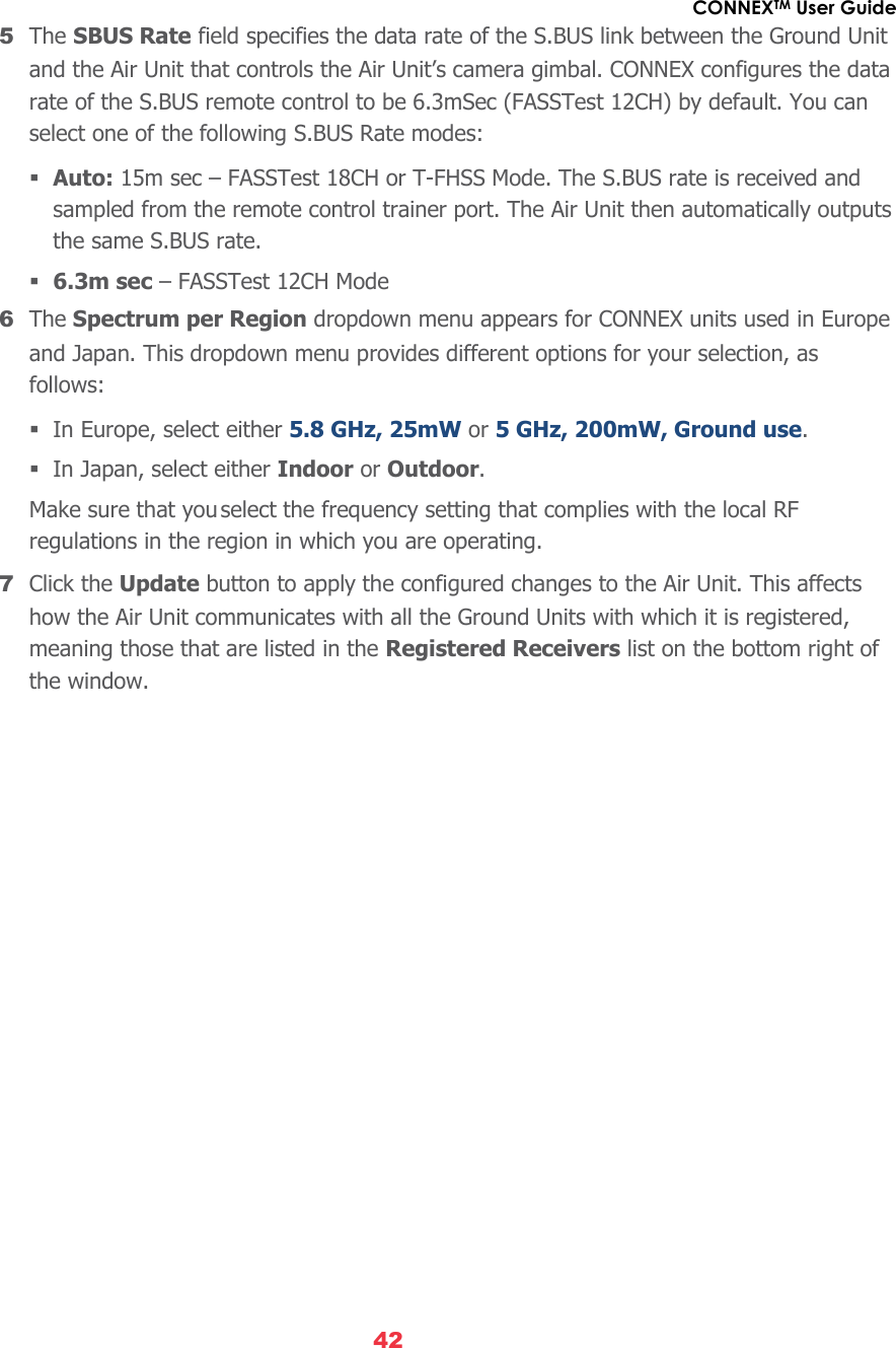
![CONNEXTM User Guide 21 Table 3: Air Unit – Power LED On (White) The Air Unit is powered on. Off No power is being supplied to the Air Unit. Blinks Quickly Indicates a system error. 8 The Air Unit automatically connects with the powered on Ground Units that are paired with this Air Unit. A connection is established between the Air and Ground Units regardless of whether video is transmitted on the wireless link, as follows: If video is transmitting, then the Ground Units display the video. If video is not transmitting, then the Ground Units display the message: Video signal not detected upon linking to the Air Unit. The Air Unit’s video and transmission status is indicated by its LEDs, as described below: Table 4: Air Unit – Video LED On (White) The video signal from the camera is locked, meaning that it is being correctly received by the Air Unit from the camera. Off The video from the camera is not locked, meaning that the Air Unit is not receiving the video from the camera. Blinks Quickly The Air Unit is powered down or the camera is transmitting a video resolution that is not supported by the Air Unit. Table 5: Air Unit – Network LED On (White) A link has been established to the Ground Unit, meaning that video is being transmitted to it. Off The Air Unit is not broadcasting because it has not recognized any Ground Units with which it was paired previously. Blinks Quickly The Air Unit is pairing with a Ground Unit or the Air Unit has gone out of range of the Ground Unit and is searching for it. Blinks Slowly The Air Unit is establishing a link with a Ground Unit. Blinks Very Slowly The Air Unit is searching for an available frequency on which to transmit. Note: This may take up to 70 seconds when working outdoors in Japan. 9 [Optional] To display information received from the aircraft’s flight controller overlaid on the video on the Ground Unit monitor, you may refer to the Connecting the Telemetry Port section on the following page.](https://usermanual.wiki/Amimon/AMNBZT1/User-Guide-2610790-Page-21.png)

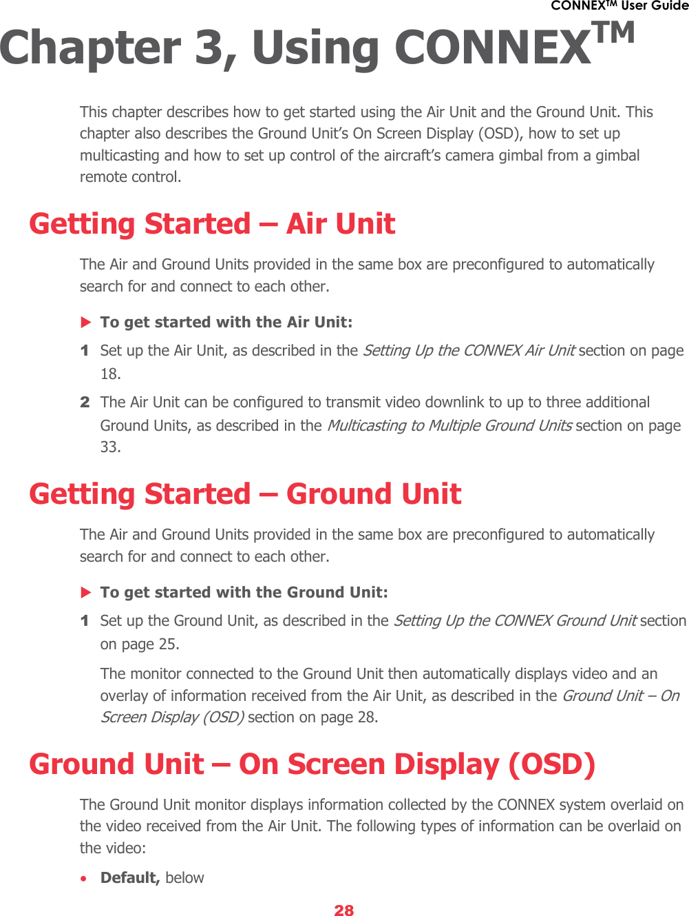
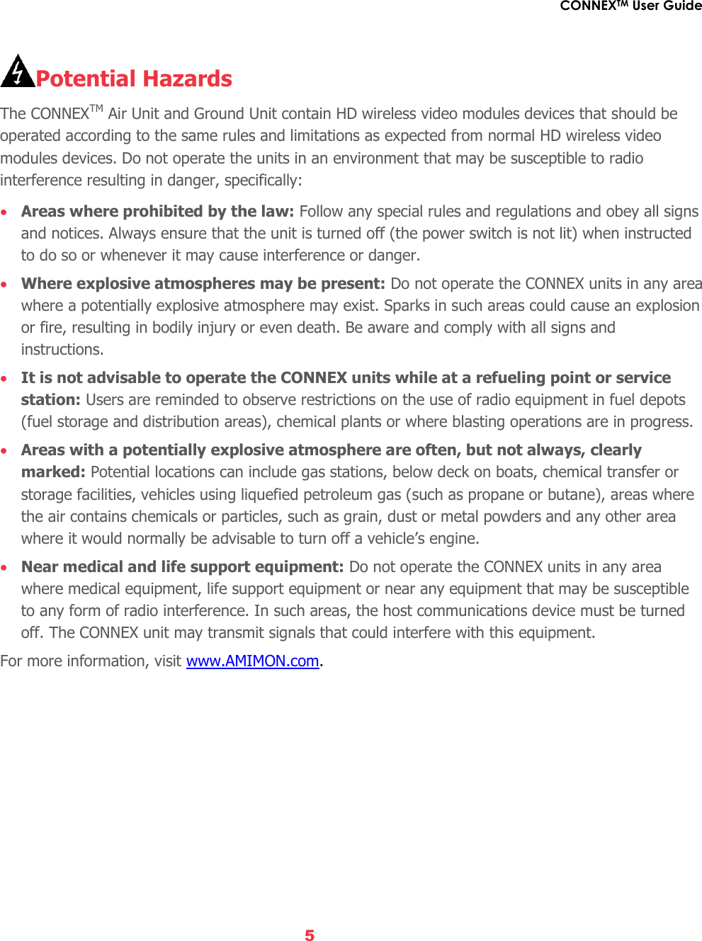
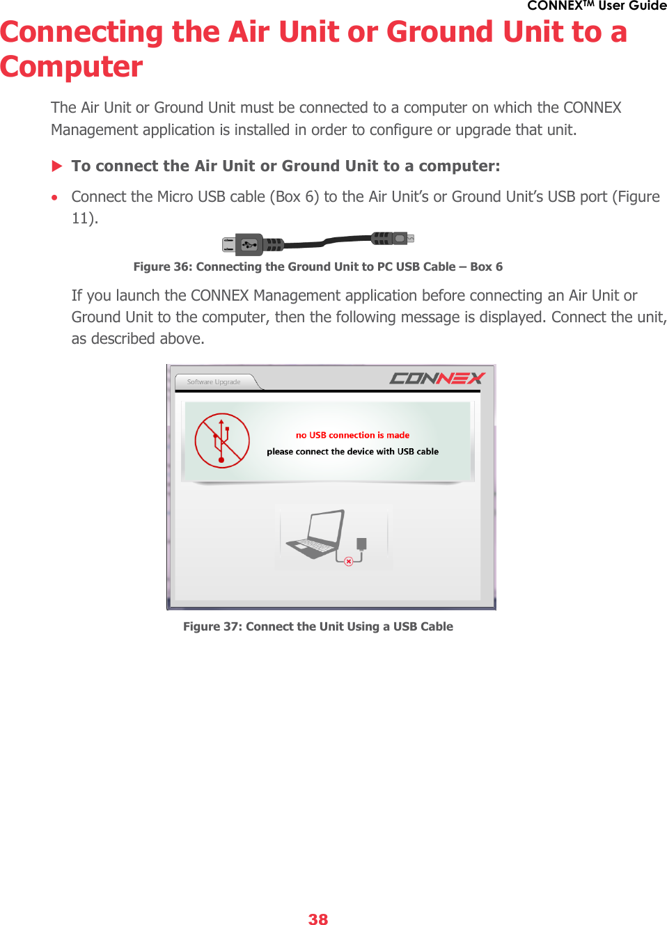
![CONNEXTM User Guide 29 Telemetry [Optional], page 30 Alerts and System Messages, page 32 Default Information Overlaid on Video By default, the Ground Unit displays the following information overlaid on the bottom of the video in a black strip: Figure 31: OSD ON – Default View : Distance of the Air Unit from the Ground Unit : Video resolution captured by the aircraft camera : Air Unit to Ground Unit video signal strength : Air Unit power voltage level By default, this OSD information is enabled (displayed). Pressing the OSD button (shown in Table 2) on the Ground Unit disables (hides) this OSD information. Pressing this button again redisplays it. Default information overlay on video](https://usermanual.wiki/Amimon/AMNBZT1/User-Guide-2610790-Page-29.png)
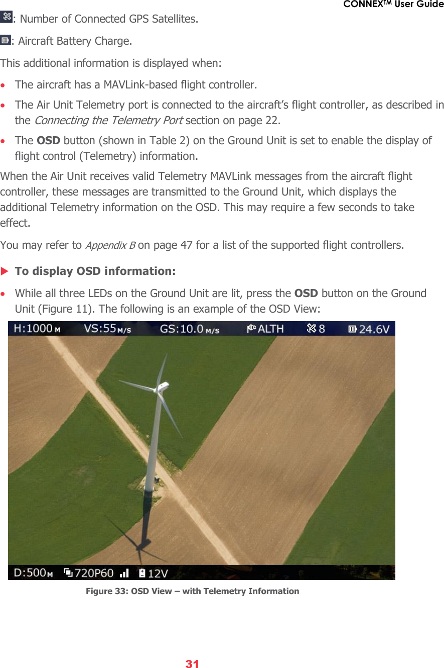
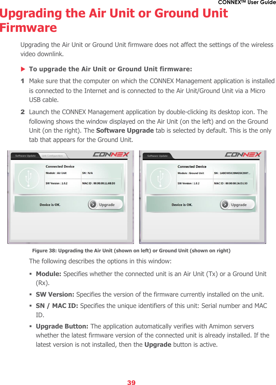

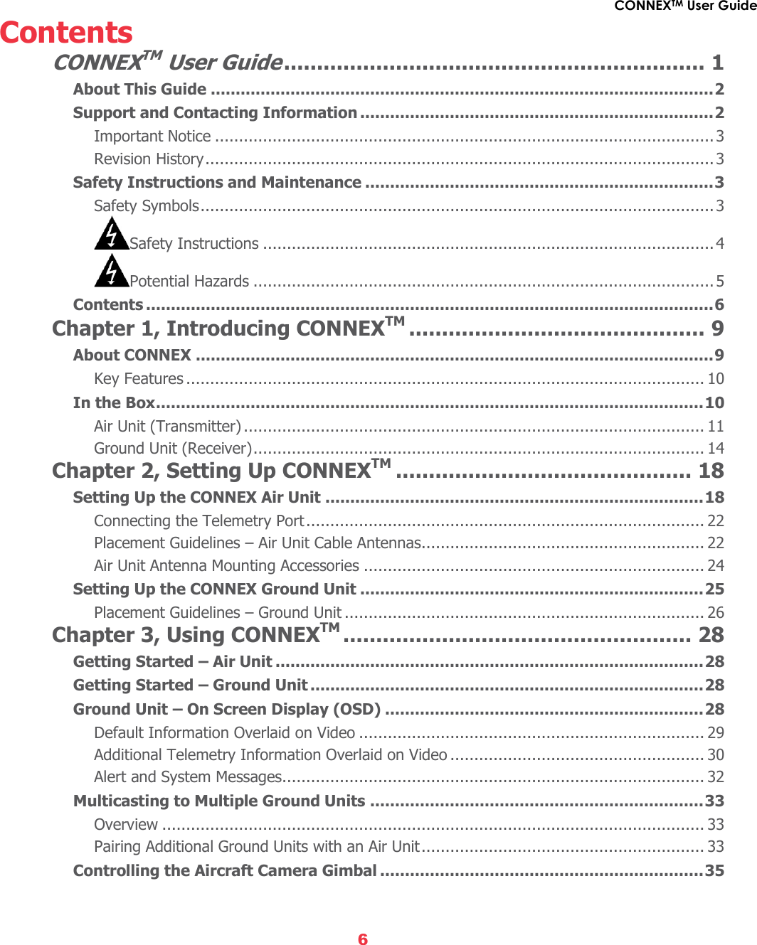
![CONNEXTM User Guide 46 Appendix A, Technical Specifications Table 14: CONNEX Technical Specifications Transmission Distance Outdoor Up to 1,000m/3,000 ft. (LoS) Transmission Delay Zero [Less than 1 msec.] Radio Frequency 5.1-5.8 GHz, 17 channels Channel Selection Automatic frequency selection [AFS] Video Formats 60/59.94, 1080p/50, 1080i/60, 1080i/50, 30/29.97, 24/23.98, 60/59.94, 720p/50, 480i/60, 576i/50 Multicast Mode Up to 4 receivers with no delay or quality degradation. [Requiring extra Ground Unit(s)] OSD Support MAVLink Telemetry based Encryption AES-128 & RSA 1024 for key exchange Operating Temperature -10 - 50o Celsius Regulation CE, FCC, MIC Air Unit Ground Unit Video Interface Mini HDMI HDMI (Type A) Antenna Connectors MMCX (x2) SMA (x5) Power Connector 4-pins DC round Power Input 8-26V (3S-6S) 7-17V Dimensions (mm) 103 x 63.6 x 15.6 129 x 89 x 20 Weight 120 grams 290 grams](https://usermanual.wiki/Amimon/AMNBZT1/User-Guide-2610790-Page-46.png)