Amimon AMNKHEX1 HD-SDI wireless transmitter module User Manual
Amimon Ltd. HD-SDI wireless transmitter module
UserManual.wiki
>
Amimon
>
AMNKHEX1 User Manual
User Manual
Navigation menu
Upload a User Manual
Namespaces
Wiki Guide
HTML
PDF
Info
Views
User Manual
Discussion / Help
Navigation
![Operating modes Aerial mode In this mode a link is established between a single receiver and a single transmitter. This mode uses DFS frequencies as well making it flexible and easy to adjust to all different fields of use and to meet the regional and national frequency requirements and laws. For some SkyLink version the message "please wait 60 seconds" may appear on the monitor when the link is first established to inform the user that the system is searching for a free DFS frequency. In this case this message will be followed by a second identical message to inform that the system is searching for an alternative DFS frequency. Upon completion the message "Ready" will appear on the monitor. In Aerial mode a link can be established only if the systems are within close proximity to each other. If either receiver or transmitter is reset, both sides must be brought close together and reset in order to re-establish the link. Operating Frequencies FREQUENCIES [MHz] DESCRIPTION 5270 DFS 5310 DFS 5510 DFS 5550 DFS 5590 DFS 5630 DFS 5670 DFS 5755 ISM; Non-DFS 5795 ISM; Non-DFS](https://usermanual.wiki/Amimon/AMNKHEX1/User-Guide-2213307-Page-17.png)
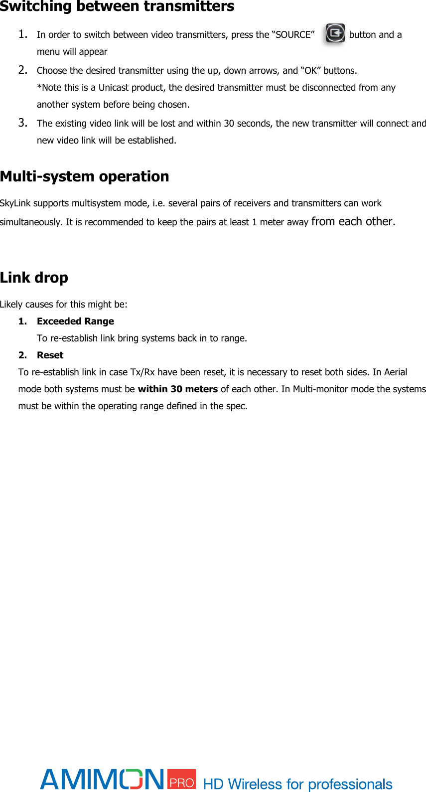
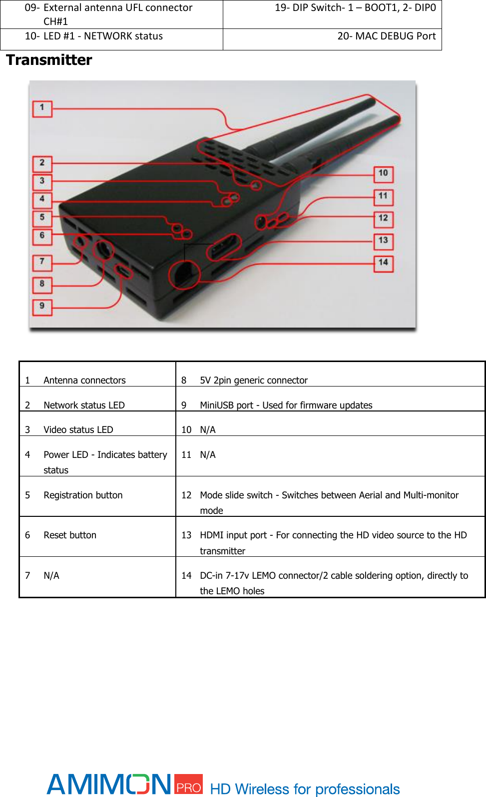
![Multi-monitor mode In this mode a single transmitter can establish a link with several receivers. A link can be established even when the systems are not within close proximity to each other. Operating Frequencies FREQUENCIES [MHz] DESCRIPTION 5755 Non-DFS 5795 Non-DFS Switching between Aerial and Multi-monitor modes Switching between Aerial and Multi-monitor will be done by toggling DIP switch #4 on the Rx side and sliding Mode Slide switch on the Tx side. Switching between modes will reset the systems.](https://usermanual.wiki/Amimon/AMNKHEX1/User-Guide-2213307-Page-18.png)
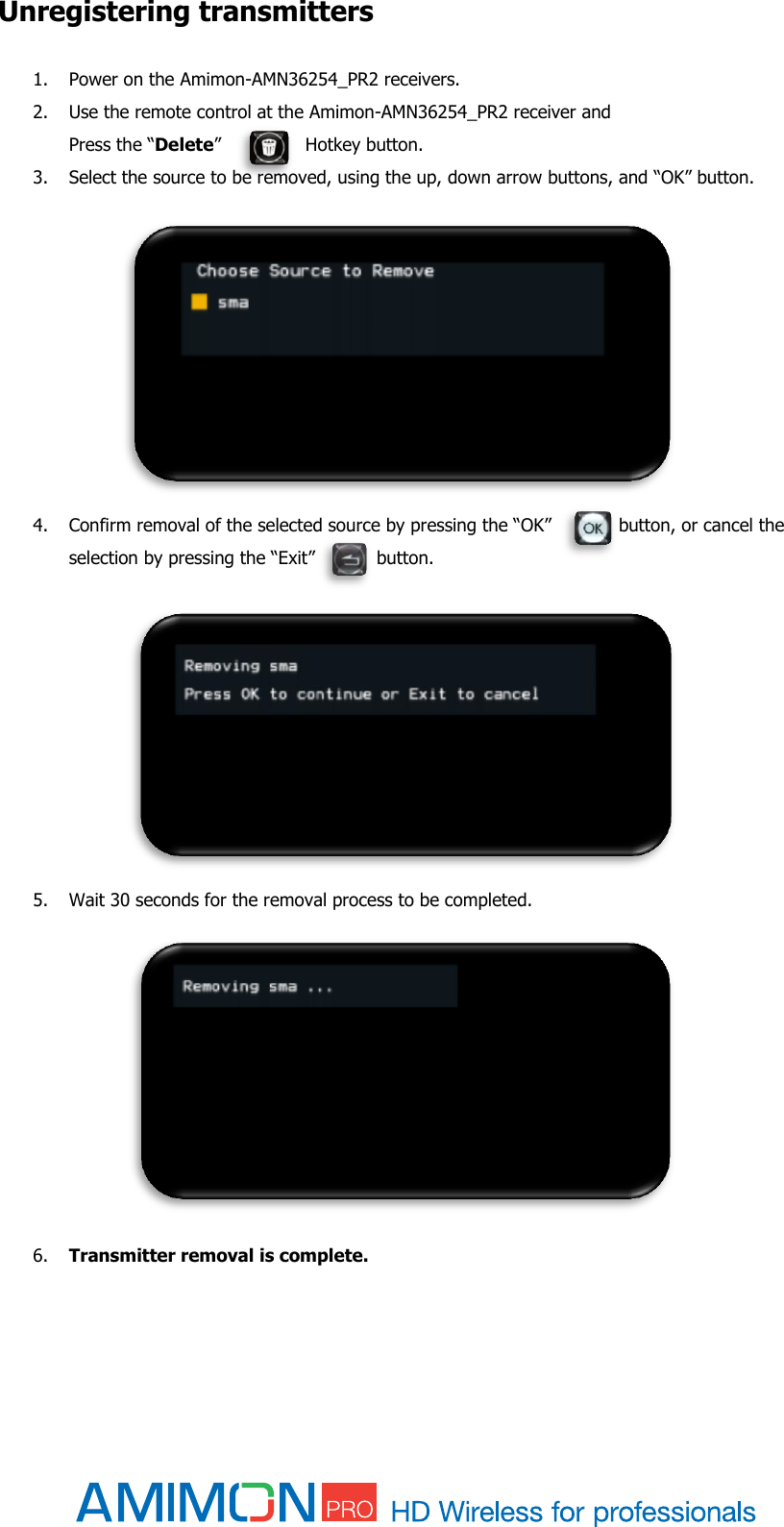
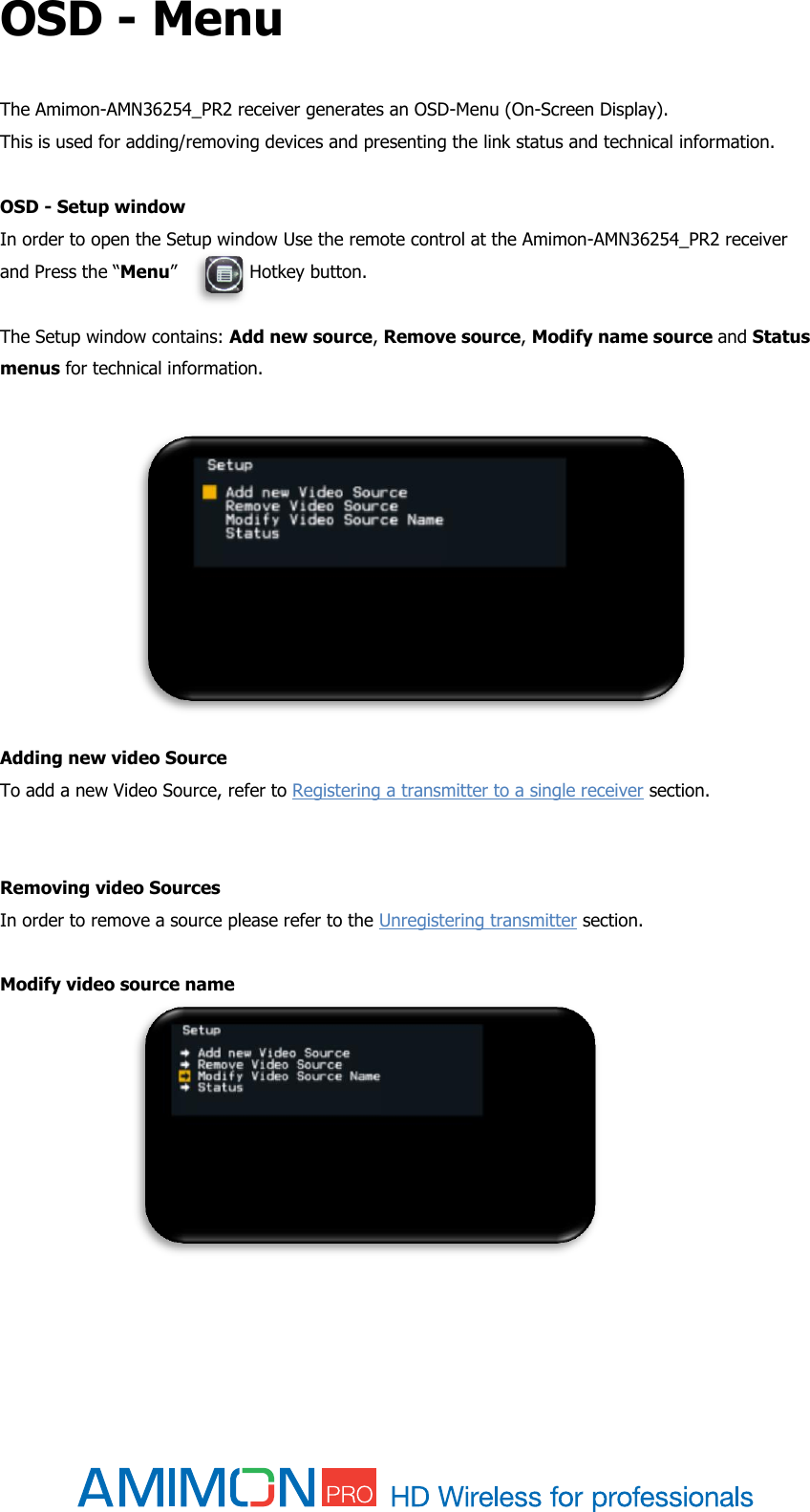
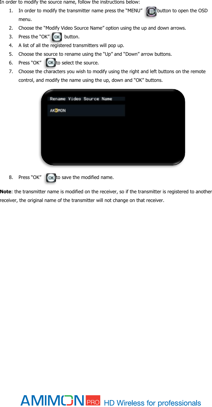
![Registration Amimon products require registration between the transmitter and receiver, in order to establish a wireless link. The registration process includes keys exchange, for enhanced security and can be managed using the remote control, provided with the product. Sets of Amimon - AMN35223_PB transmitter and Amimon-AMN36254_PR2 receiver usually arrive pre-paired, when purchased as pairs. In such case, video link will be established automatically after completing installation. The registration is required only once, and after registration, the sets of transmitters and receivers will connect automatically upon boot up. Important: Registration must be done when the system are in Aerial mode. Registering a transmitter to a single receiver If there is no transmitter registered to the receiver, you should see an OSD menu on the monitor. 1. Connect the HD Source to the Amimon - AMN35223_PB transmitter. 2. Connect a HD-SDI cable from the Amimon-AMN36254_PR2 receiver to the HD display*. 3. Turn on the transmitter and receiver. 4. Use the remote control on the Amimon-AMN36254_PR2 receiver and Press the “Add” Hotkey button. 5. The message “Please Activate the Registration on Transmitter Unit” will appear on the monitor. 6. Press the registration button on the transmitter until the “Network” LED starts blinking. 7. Wait for OSD message of "Adding [Tx name] Press OK to continue or Exit to cancel". 8. Press the “OK” button on the Remote control to confirm the addition of a new Amimon - AMN35223_PB transmitter. 9. Wait until the registration process is complete. An OSD message of " Adding [Tx name]…"and a progress bar will appear during the process. 10. Video link is established. *The registration process can be done without HD source, an OSD message will appear to notify of missing video source. Note: Once the registration process starts on the receiver side, it may take up to 30 seconds for the registration process to start on the transmit side. In case the registration process exceeds 30 seconds, re-start the registration process by going back to stage 4.](https://usermanual.wiki/Amimon/AMNKHEX1/User-Guide-2213307-Page-21.png)
![Registering without remote control If there is no transmitter registered to the receiver, you should see an OSD menu on the monitor. 1. Connect the HD Source to the Amimon-AMN36254_PR2 transmitter. 2. Connect a HD-SDI cable from the Amimon-AMN36254_PR2 receiver to the HD display*. 3. Turn on the transmitter and receiver. 4. Long press the Registration button [#18] on the Rx. 5. The message “Please Activate the Registration on Transmitter Unit” will appear on the monitor. 6. Press the Registration button [#5] on the Tx until the “Network” LED starts blinking. 7. Wait for OSD message of "Adding [Tx name] Press OK to continue or Exit to cancel". 8. Press the Registration button [#18] on the Rx to confirm. 9. Wait until the registration process is complete. An OSD message of " Adding [Tx name]…"and progress bar will appear during the process. 10. Video link is established. *The registration process can be done without HD source, an OSD message will appear to notify of missing video source. Registering a transmitter to multiple receivers The Amimon - AMN35223_PB transmitter has the ability to connect up to 4 receivers at a time. 1. There is a need to make sure the transmitter is not transmitting video to other receivers, so all other receivers which are registered to the transmitter should be powered down while registering an additional receiver. 2. *Connect the HD Source to the Amimon - AMN35223_PB transmitter. 3. Using HD-SDI cables connect each Amimon-AMN36254_PR2 receiver to a HD display. 4. Power on the transmitter and receiver. 5. Power on only one receiver at a time for ease of installation. 6. Use the remote control at the Amimon-AMN36254_PR2 receiver and Press the “Add” Hotkey button. 7. The message “Please Activate the Registration on Transmitter Unit” will appear on the monitor. 8. Pressing the registration button on the transmitter until the “Network” LED starts blinking. 9. Wait for OSD message of "Adding [Tx name] Press OK to continue or Exit to cancel". 10. Press the “OK” button on the IR Remote to confirm the addition of the receiver. 11. Wait until the registration process is complete. An OSD message of " Adding [Tx name]…"and progress bar will appear during the process. 12. In order to add additional receivers to the transmitter, Power down all other Amimon-AMN36254_PR2 receivers, except the latest one. 13. Repeat steps 5 through 12 for each receiver.](https://usermanual.wiki/Amimon/AMNKHEX1/User-Guide-2213307-Page-22.png)
![14. When all the receivers have been registered to the transmitter power on all the receivers one by one. 15. The video should be displayed on all monitors. *The registration process can be done without HD source, an OSD message will appear to notify of missing video source. Registering multiple transmitters to a receiver 1. Connect the HD Source to the Amimon - AMN35223_PB transmitter*. 2. Connect a HD-SDI cable from the Amimon-AMN36254_PR2 receiver to the HD display. 3. Power on the transmitter and receiver. 4. Use the remote control at the Amimon-AMN36254_PR2 receiver and Press the “Add” Hotkey button. 5. The message “Please Activate the Registration on Transmitter Unit” will appear on the monitor. 6. Pressing the registration button on the transmitter until the “Network” LED starts blinking. 7. Wait for an OSD message of "Adding [Tx name] Press OK to continue or Exit to cancel". 8. Press the “OK” button on the Remote control to confirm the new Amimon - AMN35223_PB transmitter. 9. Wait until the registration process is complete. An OSD message of " Adding [Tx name]…"and progress bar will appear during the process. 10. Video link is established. *The registration process can be done without HD source, an OSD message will appear to notify of missing video source.](https://usermanual.wiki/Amimon/AMNKHEX1/User-Guide-2213307-Page-23.png)