Amimon AMNKHIN1 HD-SDI wireless transmitter module User Manual Rev 1
Amimon Ltd. HD-SDI wireless transmitter module Rev 1
Amimon >
User Manual Rev. 1
Sky Link Indoor
User Manual
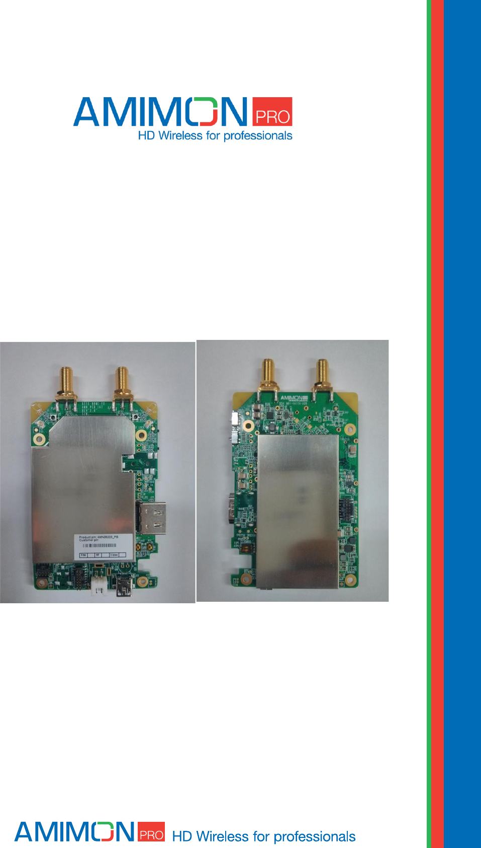
AMN0504PBLR
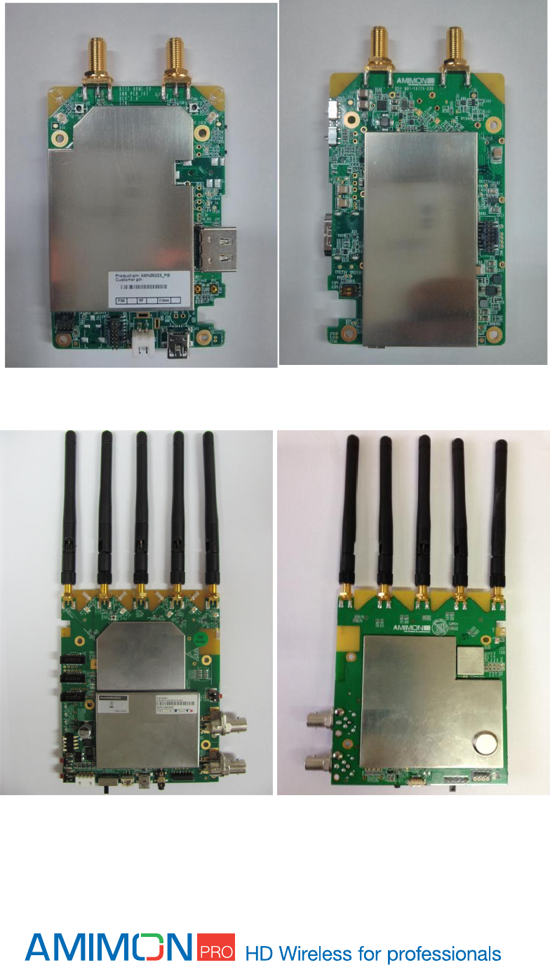
Tx - AMN35223_PM & Rx - AMN36254_PM
Tx without enclosure
www.amimon.comm
mmmmmcmצ
Rx without enclosure
An AMIMON Inc. Document
Copyright 2013
Version 1.9

Important Notice
AMIMON Ltd. reserves the right to make corrections, modifications, enhancements, improvements, and
other changes to its products and services at any time and to discontinue any product or service
without notice. Customers should obtain the latest relevant information before placing orders and
should verify that such information is current and complete. All products are sold subject to AMIMON's
terms and conditions of sale supplied at the time of order acknowledgment.
AMIMON warrants performance of its hardware products to the specifications applicable at the time of
sale in accordance with AMIMON's standard warranty. Testing and other quality control techniques are
used to the extent AMIMON deems necessary to support this warranty. Except where mandated by
government requirements, testing of all parameters of each product is not necessarily performed.
AMIMON assumes no liability for applications assistance or customer product design. Customers are
responsible for their products and applications using AMIMON components. To minimize the risks
associated with customer products and applications, customers should provide adequate design and
operating safeguards.
AMIMON does not warrant or represent that any license, either express or implied, is granted under
any AMIMON patent right, copyright, mask work right, or other AMIMON intellectual property right
relating to any combination, machine, or process in which AMIMON products or services are used.
Information published by AMIMON regarding third-party products or services does not constitute a
license from AMIMON to use such products or services or a warranty or endorsement thereof. Use of
such information may require a license from a third party under the patents or other intellectual
property of the third party, or a license from AMIMON under the patents or other intellectual property
of AMIMON.
Reproduction of information in AMIMON data books or data sheets is permissible only if reproduction is
without alteration and is accompanied by all associated warranties, conditions, limitations, and notices.
Reproduction of this information with alteration is an unfair and deceptive business practice. AMIMON
is not responsible or liable for such altered documentation.
Resale of AMIMON products or services with statements different from or beyond the parameters
stated by AMIMON for that product or service voids all express and any implied warranties for the
associated AMIMON product or service and is an unfair and deceptive business practice. AMIMON is not
responsible or liable for any such statements.
All company and brand products and service names are trademarks or registered trademarks of their
respective holders.
Avis Important
AMIMON Ltd. se réserve le droit d'apporter des corrections, modifications, améliorations et autres
changements à ses produits et services à tout moment, et de mettre fin à tout produit ou service sans
préavis. Les clients doivent obtenir les dernières informations pertinentes avant de passer commande et
doivent vérifier que ces informations sont à jour et complètes. Tous les produits sont vendus selon les
termes et conditions de vente d'AMIMON fournis au moment de la confirmation de commande.
AMIMON garantit la conformité de ses produits manufacturés avec les spécifications en vigueur au
moment de la vente, conformément à la garantie standard AMIMON. Des tests et autres techniques de
contrôle de qualité sont effectués dans la mesure où AMIMON le juge nécessaire pour assurer cette
garantie.
Les tests de tous les paramètres de chaque produit ne sont pas nécessairement effectués, sauf s'il
s'agit de se conformer aux exigences du gouvernement.

AMIMON n'assume aucune responsabilité pour l'assistance aux applications ou aux produits conçus par
sa clientèle. Les clients sont responsables de leurs produits et des applications utilisant des composants
AMIMON. Afin de minimiser les risques associés aux produits et aux applications des clients, les clients
doivent fournir une conception adéquate et des garanties d'exploitation.
AMIMON ne garantit ni ne déclare que toute licence, explicite ou implicite, soit accordée en vertu d'un
brevet AMIMON, de droits d'auteur, masque droit de travail ou autre droit AMIMON de la propriété
intellectuelle relatif à toute combinaison, machine ou processus dans lesquels les produits ou services
AMIMON sont utilisés. Les informations publiées par AMIMON sur les produits ou services de tiers ne
constituent pas une licence de AMIMON d'utiliser de tels produits ou services, ni une garantie ou une
approbation de cette utilisation. L'utilisation de tels renseignements peut exiger une licence d'un tiers
en vertu des brevets ou autre propriété intellectuelle de tiers, ou une licence de AMIMON en vertu des
brevets ou autre propriété intellectuelle de AMIMON.
La reproduction d'informations dans les livres de données AMIMON ou les fiches de données n'est
autorisée que si celle-ci est faite sans modification et est accompagnée par toutes les garanties
associées, conditions, restrictions et avis. La reproduction de ces informations avec une modification est
une pratique commerciale déloyale et trompeuse. AMIMON n'est pas responsable d'une telle
documentation modifiée.
La revente de produits ou services AMIMON avec des déclarations différentes ou au-delà des
paramètres énoncés par AMIMON pour ce produit ou service annule toute garantie implicite ou explicite
pour le produit AMIMON ou service associé, et constitue une pratique commerciale déloyale et
trompeuse.
AMIMON n'est pas responsable de, ni engagé par ces déclarations.
Tous les noms de produit ou de service d'une compagnie ou d'une marque sont des marques
commerciales ou des marques déposées par leurs détenteurs respectifs.
FCC Warning
Changes or modifications not expressly approved by the party responsible for compliance could void the
user’s authority to operate the equipment.
NOTE: This equipment has been tested and found to comply with the limits for a Class B digital device,
pursuant to part 15 of the FCC Rules. These limits are designed to provide reasonable protection against
harmful interference in a residential installation. This equipment generates, uses and can radiate radio
frequency energy and, if not in-stalled and used in accordance with the instructions, may cause harmful
interference to radio communications. However, there is no guarantee that interference will not occur in a
particular installation. If this equipment does cause harmful interference to radio or television reception,
which can be determined by turning the equipment off and on, the user is encouraged to try to correct the
interference by one or more of the following measures:
- Reorient or relocate the receiving antenna.
- Increase the separation between the equipment and receiver.
- Connect the equipment into an outlet on a circuit different from that to which the receiver is connected.
- Consult the dealer or an experienced radio/ TV technician for help.
General Warning
This system must be used indoors only!

Revision History
Version
Date
Description
1.0
05 May 2013
Initial Draft
1.1
07 May 2013
Initial Draft
1.2
18/08/2013
Changed the input voltage value
1.3
29/10/2013
Fixed the product number
1.4
28/11/2013
Add registration with button, Update the Equipment list
1.5
31/12/2013
General overhaul
1.6
20/1/2014
Inserting notice in French and FCC Warning
1.7
19/2/2014
Supports MAC 30.0
1.8
23/02/2014
Added more detail
1.9
25/02/2014
New design

Table of Contents
Safety Instructions ..................................................................................................... 8
Caution ...................................................................................................................... 8
Overview .................................................................................................................... 9
Package Contents .................................................................................................... 10
Product Description .................................................................................................. 11
Transmitter .......................................................................................................... 11
Slide switch - operation mode selection................................................................ 13
LED behaviors – Transmitter ................................................................................ 13
Receiver ............................................................................................................... 14
LED behaviors - Receiver ...................................................................................... 15
ON/OFF Slide switch - operation mode selection .................................................. 15
DIP switches - operation mode selection .............................................................. 16
Operating modes ..................................................................................................... 17
Aerial mode .......................................................................................................... 17
Multi-monitor mode .............................................................................................. 18
Switching between Aerial and Multi-monitor modes ............................................. 18
Installation ............................................................................................................... 19
Transmitter .......................................................................................................... 19
Receiver ............................................................................................................... 19
Remote control ........................................................................................................ 20
Remote Control Hotkeys ....................................................................................... 20
Registration ............................................................................................................. 21
Registering a transmitter to a single receiver ....................................................... 21
Registering without remote control ...................................................................... 22
Registering a transmitter to multiple receivers ..................................................... 22
Registering multiple transmitters to a receiver ..................................................... 23
Unregistering transmitters .................................................................................... 24
Switching between transmitters ........................................................................... 25
Multi-system operation ......................................................................................... 25
Link drop .............................................................................................................. 25

OSD - Menu ............................................................................................................. 26
Link Quality Indicator ............................................................................................... 28
Technical Specifications ........................................................................................... 29
Specifications ....................................................................................................... 30
Troubleshooting ....................................................................................................... 31
Other malfunctions .................................................................................................. 33
Appendix .................................................................................................................. 34
Safety Instructions
When operating this equipment, read and follow all the instructions in this manual.
Do not open unit.
Do not block the air ventilation openings.
Use only accessories specified or recommended by Amimon.
When devices are switched on keep away at least 20 cm from your body.
Do not expose to moisture or excessive heat.
Keep away from water
Use the mains plug to disconnect the apparatus.
Clean with a dry cloth only.
Unplug this apparatus during lightning storms or when unused for long periods of time.
To reduce the risk of fire or electric shock, refer servicing to qualified service personnel.
Keep these instructions in a safe and accessible place for future use.
Explanation of graphical symbols:
High Voltage Sign: warns the user of the presence of uninsulated "dangerous
voltage" within the product enclosure, which may be of sufficient magnitude to
constitute a risk.
General Warning Sign: warns the user of the presence of important operating
and maintenance (servicing) instructions in the product manual.
Caution
The AMN35223_PB supports two types of power input connection:
One will be the 2-pin generic connector and the second should be soldering the 2
cables directly to the LEMO holes, but do not connect them together.

Overview
The HD SkyLink system was designed to establish wireless HD video signal transmission without any
latency over large distances. Amimon finally made this possible with revolutionary technology!
The HD SkyLink is a lightweight but still very powerful wireless HD system, which is the perfect solution
for live streaming from your multicopter or from a steadycam system.
The HD SkyLink transmits encoded but uncompressed signals. Broadcasting is therefore possible
without any delay (latency less than 1ms). This is the ideal live streaming equipment for sports events,
movies and TV productions and also industrial and inspection and monitoring related applications.
Multicasting is supported - the signal of one transmitter can be received by multiple receivers at the
same time, which allows parallel streaming and live preview for the camera operator during recording.
You have the possibility to set the used frequencies (according to the planned usage and the
frequencies assigned by the Federal Network Agency) on location via USB port. The system allows you
to have full control and you can follow the legal regulations of your country or region.
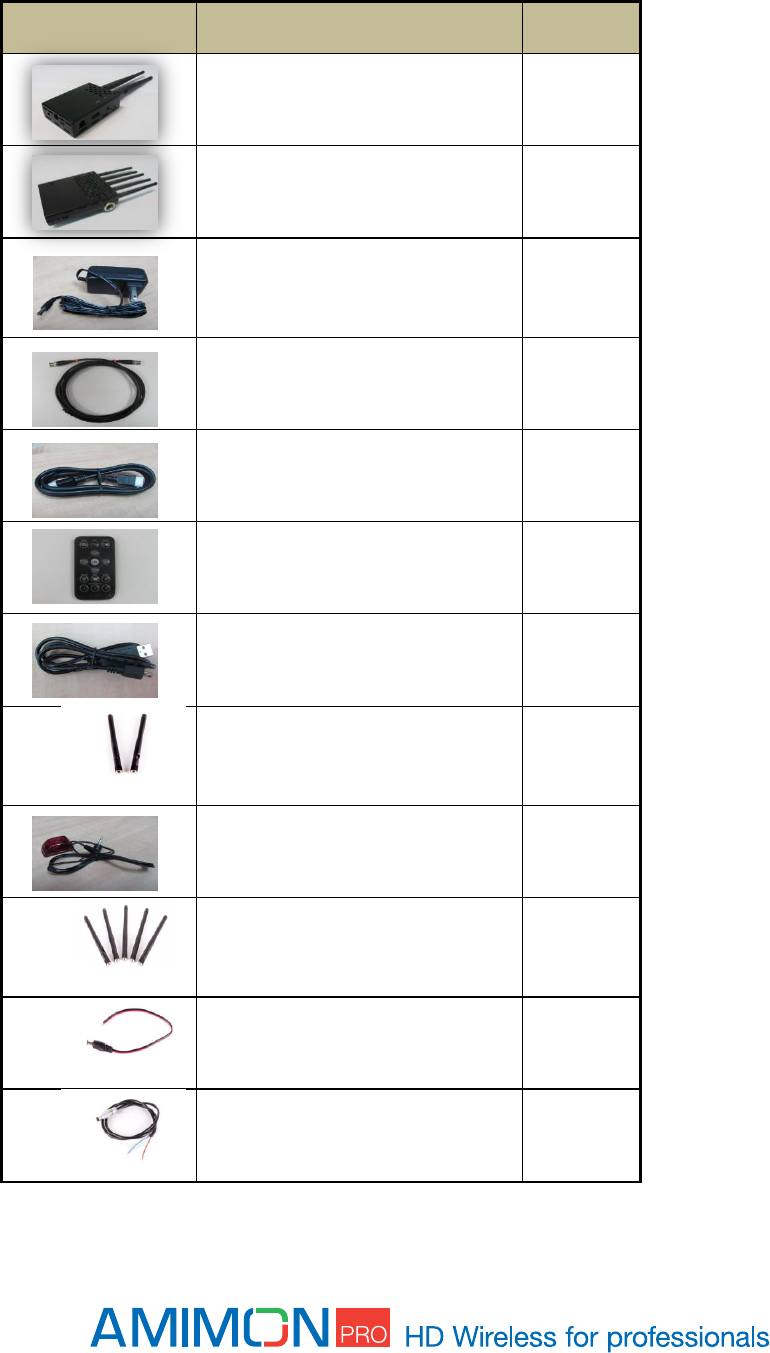
Package Contents
Please verify the following items are in the shipping box, prior to installation of the - AMN35223_PB
transmitter and Amimon-AMN36254_PR2 receiver:
ITEM
DESCRIPTION
QUANTITY
HD wireless video transmitter
1
HD-SDI wireless video receiver
1
12V Power Supply (optional)
(optional)
2
SDI cable (optional)
1
HDMI cable (optional)
1
Remote Control (optional)
1
USB to mini USB cable (optional)
1
2/5dbi (depending on region) OMNI
directional antennas for Transmitter
(optional)
2
z
IR Receiver (optional)
1
2dbi OMNI directional antennas for
Receiver (optional)
5
Cylindrical DC power cable(optional)
1
LEMO power cable(optional)
1
Product Description
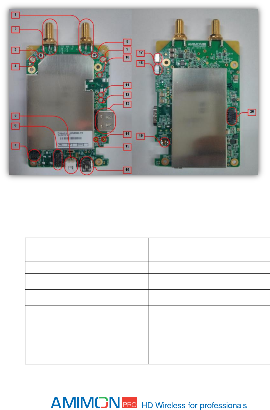
1.1.1 AMN35223 - General Guidelines (Tx)
Figure 1 - Tx AMN35223
Description of all connectors and their functionality including USB, Pass through, power
conn pin out
debug connectors,
1.1.1.1 Parts description
01- Ext antenna RP-SMA connector CH#1
11- LED #2 - VIDEO status
02- Ext antenna RP-SMA connector CH#0
12- LED #3 - Low battery LED
03- RF Push coaxial connector CH#0
13- HDMI female connector
04- External antenna UFL connector
CH#0
14- Reset Button
05- 7-17v Input Voltage connector (2
Pin)
15- Registration & Boot button
06- APP debug Port
16- USB connector
07- External host connector
17- Slide switch #2 – Operation mode
selector
08- RF Push coaxial connector CH#1
18- Slide switch #1 – Operation mode
selector
09- External antenna UFL connector
CH#1
19- DIP Switch- 1 – BOOT1, 2- DIP0
10- LED #1 - NETWORK status
20- MAC DEBUG Port
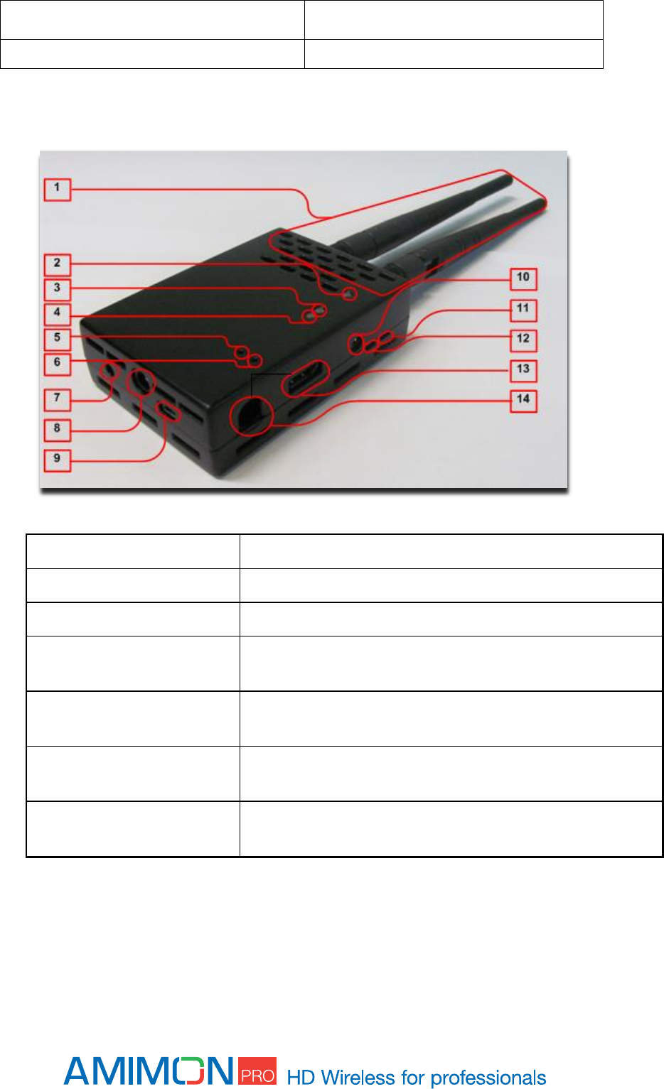
Transmitter in enclosure
1 Antenna connectors
8 5V 2pin generic connector
2 Network status LED
9 MiniUSB port - Used for firmware updates
3 Video status LED
10 N/A
4 Power LED - Indicates battery
status
11 N/A
5 Registration button
12 Mode slide switch - Switches between Aerial and Multi-monitor
mode
6 Reset button
13 HDMI input port - For connecting the HD video source to the HD
transmitter
7 N/A
14 DC-in 7-17v LEMO connector/2 cable soldering option, directly to
the LEMO holes
Slide switch - operation mode selection
LED behaviors – Transmitter
Network LED
BLINKING MODE
DESCRIPTION
Solid
When a connection to Rx is established
Slow
Device is in listen mode
Normal
During link setup mode/during Registration
Fast
System Error (Video LED flashing as well)
Video LED
BLINKING MODE
DESCRIPTION
Solid
Video signal is locked
Normal
Video is not supported
Fast
System Error (Network LED flashing as well)
Power LED
BLINKING MODE
DESCRIPTION
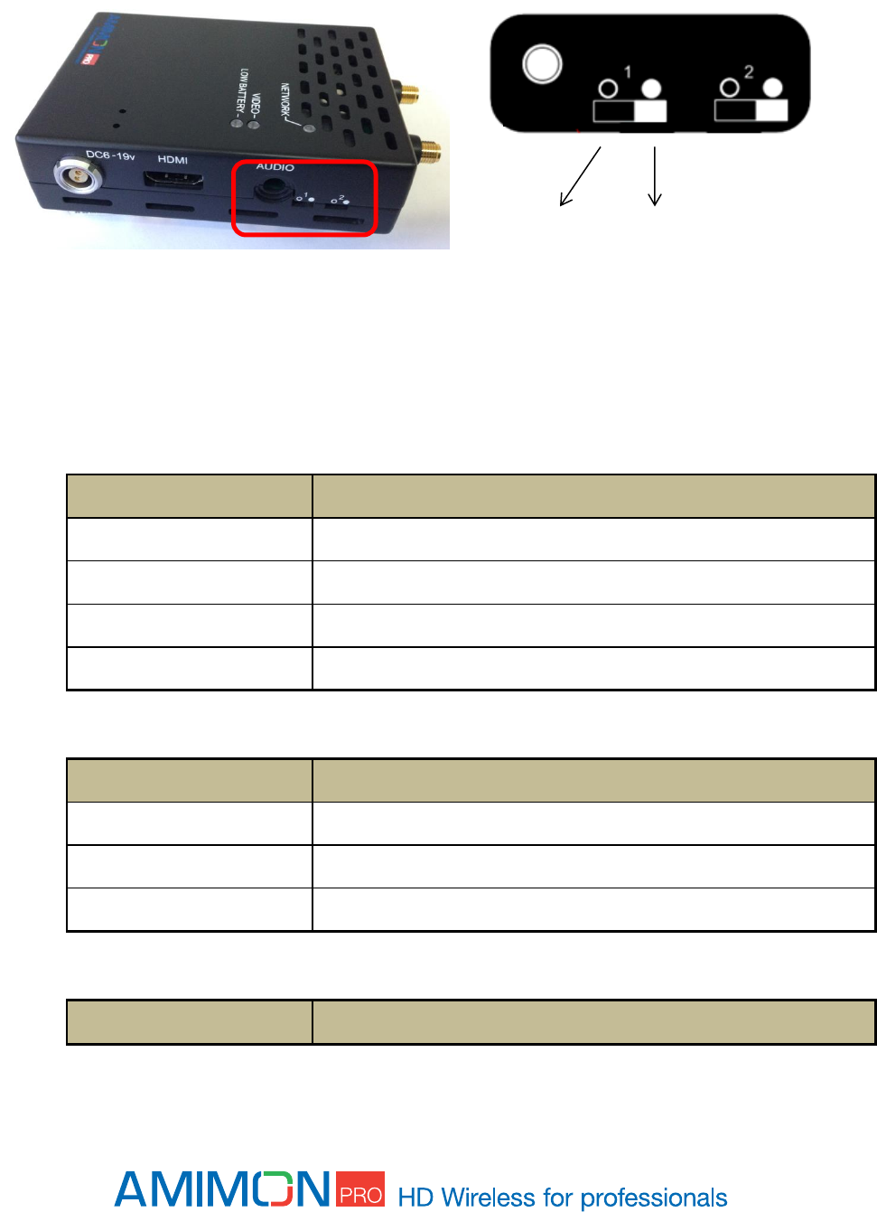
Mode Slide Switch
Aerial
mode
Not in use
Multi-monitor
mode
AUDIO
Solid
Low battery – when voltage is less then 6.5v
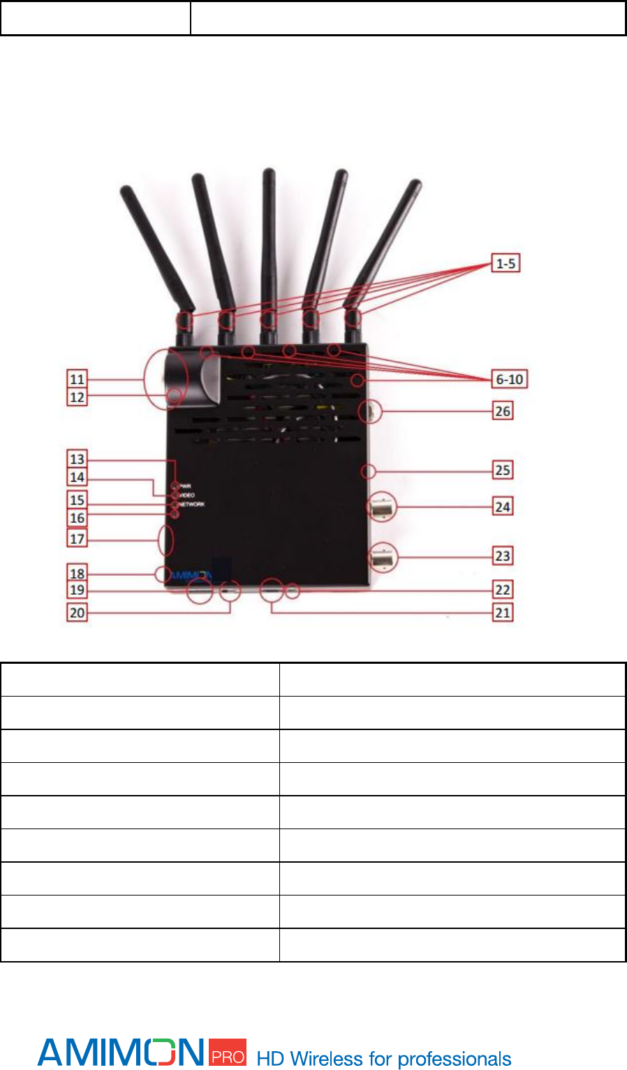
Receiver in enclosure
1-5 External antennas
18 Registration Button/Link quality button
6-10 Internal antennas
19 Input voltage connector 7-17v
11 Power connector 7-17v
20 ON/OFF switch
12 DFS antenna (located on the other side)
21 USB port
13 Power LED
22 IR input connector
14 Video LED
23 HD-SDI output
15 Network LED
24 2D-SDI output
16 N/A
25 Reset button
17 DIP switches
26 DC power connector 7-17v
LED behaviors - Receiver
Network LED
BLINKING MODE
DESCRIPTION
Solid
When a connection to Tx is established*/Link quality is good
Slow
Device is in listen mode/Link quality is reasonably good
Normal
During link setup mode/during registration
Fast
System Error (Video LED flashing as well)/Link quality is poor
*In Aerial mode even when Tx is out of range.
Video LED
BLINKING MODE
DESCRIPTION
Solid
Video signal is locked
Fast
System Error (Video LED flashing as well)
Power LED
BLINKING MODE
DESCRIPTION
Solid
Power is supplied and ON/OFF switch is on
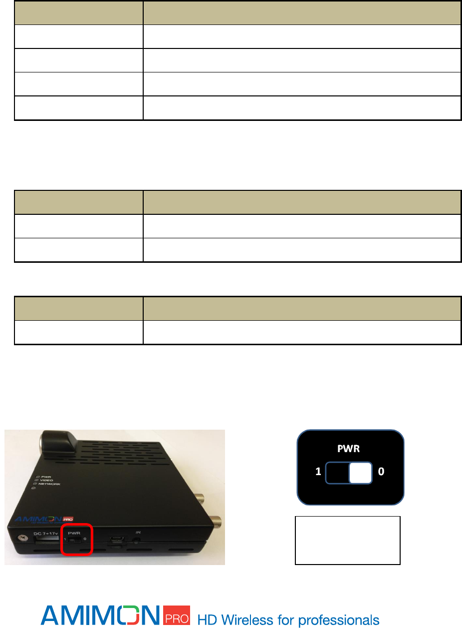
ON/OFF Slide switch - operation mode selection
1 – Powered ON
0 – Powered OFF
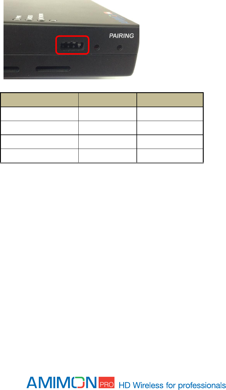
DIP switches - operation mode selection
DIP SWITCH
UP
DOWN
#1
Default
N/A
#2
Default
N/A
#3
Default
N/A
#4
Aerial mode
Multi-Monitor mode
Operating modes
Aerial mode
In this mode a link is established between a single receiver and a single transmitter. This mode uses
DFS frequencies as well making it flexible and easy to adjust to all different fields of use and to meet
the regional and national frequency requirements and laws.
For some SkyLink version the message "please wait 60 seconds" may appear on the monitor when the
link is first established to inform the user that the system is searching for a free DFS frequency. In this
case this message will be followed by a second identical message to inform that the system is
searching for an alternative DFS frequency. Upon completion the message "Ready" will appear on the
monitor.
In Aerial mode a link can be established only if the systems are within close proximity to each other. If
either receiver or transmitter is reset, both sides must be brought close together and reset in order to
re-establish the link.
Operating Frequencies
FREQUENCIES [MHz]
DESCRIPTION
5190
Non-DFS
5230
Non-DFS
5270
DFS
5310
DFS
5510
DFS
5550
DFS
5590
DFS
5630
DFS
5670
DFS
5755
Non-DFS
5795
Non-DFS

Multi-monitor mode
In this mode a single transmitter can establish a link with several receivers. A link can be established
even when the systems are not within close proximity to each other.
Operating Frequencies
FREQUENCIES [MHz]
DESCRIPTION
5190
Non-DFS
5230
Non-DFS
5755
Non-DFS
5795
Non-DFS
Switching between Aerial and Multi-monitor modes
Switching between Aerial and Multi-monitor will be done by toggling DIP switch #4 on the Rx side and
sliding Mode Slide switch on the Tx side. Switching between modes will reset the systems.
Installation
Transmitter
See Transmitter Product Description for port location described in this section.
1. Switch on Source.
2. Connect the Amimon - AMN35223_PB transmitter to the HD video source via HDMI input port
(port #13).
3. Connect the Amimon - AMN35223_PB transmitter to the 7-17v power, via the Lemo connector
(port #14).
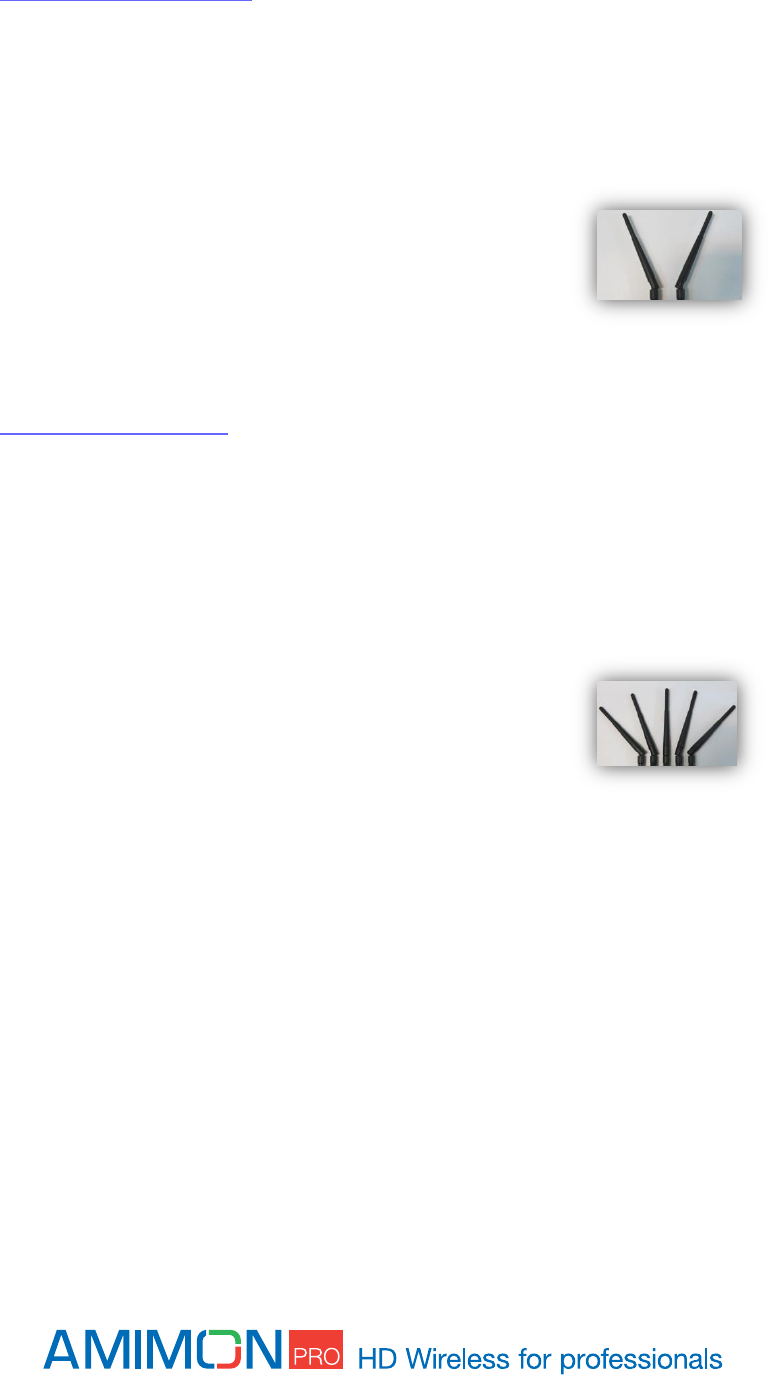
4. Antenna orientation: It is recommended to separate the
antennas so that they form a "V" (as shown in the picture).
Receiving antennas should be oriented in the same plane as the
transmitting antenna.
Receiver
See Receiver Product Description for port location described in this section.
1. Switch on Monitor.
2. Connect the Amimon-AMN36254_PR2 receiver to the video sink (monitor) using a HD-SDI
cable via HD-SDI output (port #23/#24).
3. Make sure all DIPs on DIP Switch are up (port #17).
4. Connect the Amimon-AMN36254_PR2 receiver to the "Input Voltage connector 7-17v", using
the power supply (port #19).
5. Enable Power on by sliding the slide Switch #20 left.
6. Antenna orientation: It is recommended to separate the
antennas to match the picture. Receiving antennas should be
oriented in the same plane as the transmitting antenna.
Note: For maximal range
Keep line of sight between the transmitter and the receiver.
Avoid placing any obstacles besides the transmitter or the receiver.
Position both transmitter and receiver in an upwards position, for enhanced antennas
performance.
Mount the Amimon - AMN35223_PB transmitter and the Amimon-AMN36254_PR2 receiver
with proper air ventilation.
Bring the transmitter and receiver closer together while trying to maintain at least 1 meter
between them.
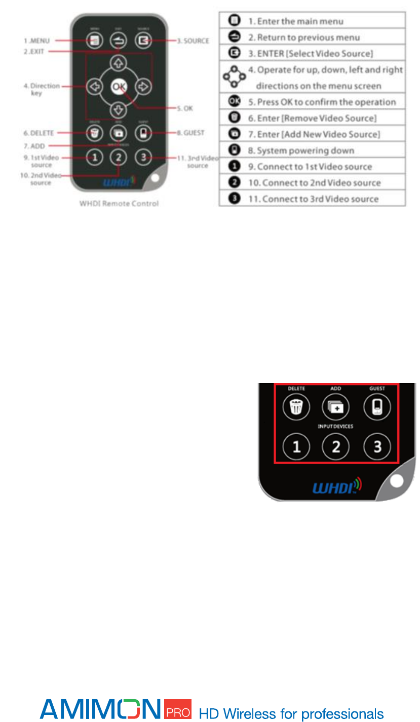
Remote control
Remote Control Hotkeys
ADD - Direct access for starting the registration process on the receiver.
Delete - will open the "Remove Video Source" in the OSD menu to allow the user to choose
to remove devices from the list of registered devices.
Video Source Keys – These three keys (1st/2nd/3rd Video Source) will toggle between the
first, second or third source registered with the receiver, in order of appearance on the
registered sources list.
Registration
Amimon products require registration between the transmitter and receiver, in order to establish a
wireless link. The registration process includes keys exchange, for enhanced security and can be
managed using the remote control, provided with the product.
Sets of Amimon - AMN35223_PB transmitter and Amimon-AMN36254_PR2 receiver usually arrive pre-
paired, when purchased as pairs. In such case, video link will be established automatically after
completing installation.
The registration is required only once, and after registration, the sets of transmitters and receivers will
connect automatically upon boot up.
Important: Registration must be done when the system are in Aerial mode.
Registering a transmitter to a single receiver
If there is no transmitter registered to the receiver, you should see an OSD menu on the monitor.
1. Connect the HD Source to the Amimon - AMN35223_PB transmitter.
2. Connect a HD-SDI cable from the Amimon-AMN36254_PR2 receiver to the HD display*.
3. Turn on the transmitter and receiver.
4. Use the remote control on the Amimon-AMN36254_PR2 receiver and
Press the “Add” Hotkey button.
5. The message “Please Activate the Registration on Transmitter Unit” will appear on the
monitor.
6. Press the registration button on the transmitter until the “Network” LED starts blinking.
7. Wait for OSD message of "Adding [
Tx name
] Press OK to continue or Exit to cancel".
8. Press the “OK” button on the Remote control to confirm the addition of a new Amimon
- AMN35223_PB transmitter.
9. Wait until the registration process is complete. An OSD message of " Adding [
Tx
name
]…"and a progress bar will appear during the process.
10. Video link is established.
*The registration process can be done without HD source, an OSD message will appear to notify of
missing video source.
Note: Once the registration process starts on the receiver side, it may take up to 30 seconds for the
registration process to start on the transmit side. In case the registration process exceeds 30 seconds,
re-start the registration process by going back to stage 4.
Registering without remote control
If there is no transmitter registered to the receiver, you should see an OSD menu on the monitor.
1. Connect the HD Source to the Amimon-AMN36254_PR2 transmitter.
2. Connect a HD-SDI cable from the Amimon-AMN36254_PR2 receiver to the HD display*.
3. Turn on the transmitter and receiver.
4. Long press the Registration button [#18] on the Rx.
5. The message “Please Activate the Registration on Transmitter Unit” will appear on the
monitor.
6. Press the Registration button [#5] on the Tx until the “Network” LED starts blinking.
7. Wait for OSD message of "Adding [Tx name] Press OK to continue or Exit to cancel".
8. Press the Registration button [#18] on the Rx to confirm.
9. Wait until the registration process is complete. An OSD message of " Adding [Tx name]…"and
progress bar will appear during the process.
10. Video link is established.
*The registration process can be done without HD source, an OSD message will appear to notify of
missing video source.
Registering a transmitter to multiple receivers
The Amimon - AMN35223_PB transmitter has the ability to connect up to 4 receivers at a time.
1. There is a need to make sure the transmitter is not transmitting video to other receivers, so all
other receivers which are registered to the transmitter should be powered down while
registering an additional receiver.
2. *Connect the HD Source to the Amimon - AMN35223_PB transmitter.
3. Using HD-SDI cables connect each Amimon-AMN36254_PR2 receiver to a HD display.
4. Power on the transmitter and receiver.
5. Power on only one receiver at a time for ease of installation.
6. Use the remote control at the Amimon-AMN36254_PR2 receiver and
Press the “Add” Hotkey button.
7. The message “Please Activate the Registration on Transmitter Unit” will appear on the
monitor.
8. Pressing the registration button on the transmitter until the “Network” LED starts blinking.
9. Wait for OSD message of "Adding [
Tx name
] Press OK to continue or Exit to cancel".
10. Press the “OK” button on the IR Remote to confirm the addition of the receiver.
11. Wait until the registration process is complete. An OSD message of " Adding [
Tx
name
]…"and progress bar will appear during the process.
12. In order to add additional receivers to the transmitter, Power down all other Amimon-
AMN36254_PR2 receivers, except the latest one.
13. Repeat steps 5 through 12 for each receiver.

14. When all the receivers have been registered to the transmitter power on all the receivers one
by one.
15. The video should be displayed on all monitors.
*The registration process can be done without HD source, an OSD message will appear to notify of
missing video source.
Registering multiple transmitters to a receiver
1. Connect the HD Source to the Amimon - AMN35223_PB transmitter*.
2. Connect a HD-SDI cable from the Amimon-AMN36254_PR2 receiver to the HD display.
3. Power on the transmitter and receiver.
4. Use the remote control at the Amimon-AMN36254_PR2 receiver and
Press the “Add” Hotkey button.
5. The message “Please Activate the Registration on Transmitter Unit” will appear on the
monitor.
6. Pressing the registration button on the transmitter until the “Network” LED starts blinking.
7. Wait for an OSD message of "Adding [
Tx name
] Press OK to continue or Exit to cancel".
8. Press the “OK” button on the Remote control to confirm the new Amimon -
AMN35223_PB transmitter.
9. Wait until the registration process is complete. An OSD message of " Adding [
Tx
name
]…"and progress bar will appear during the process.
10. Video link is established.
*The registration process can be done without HD source, an OSD message will appear to notify of
missing video source.
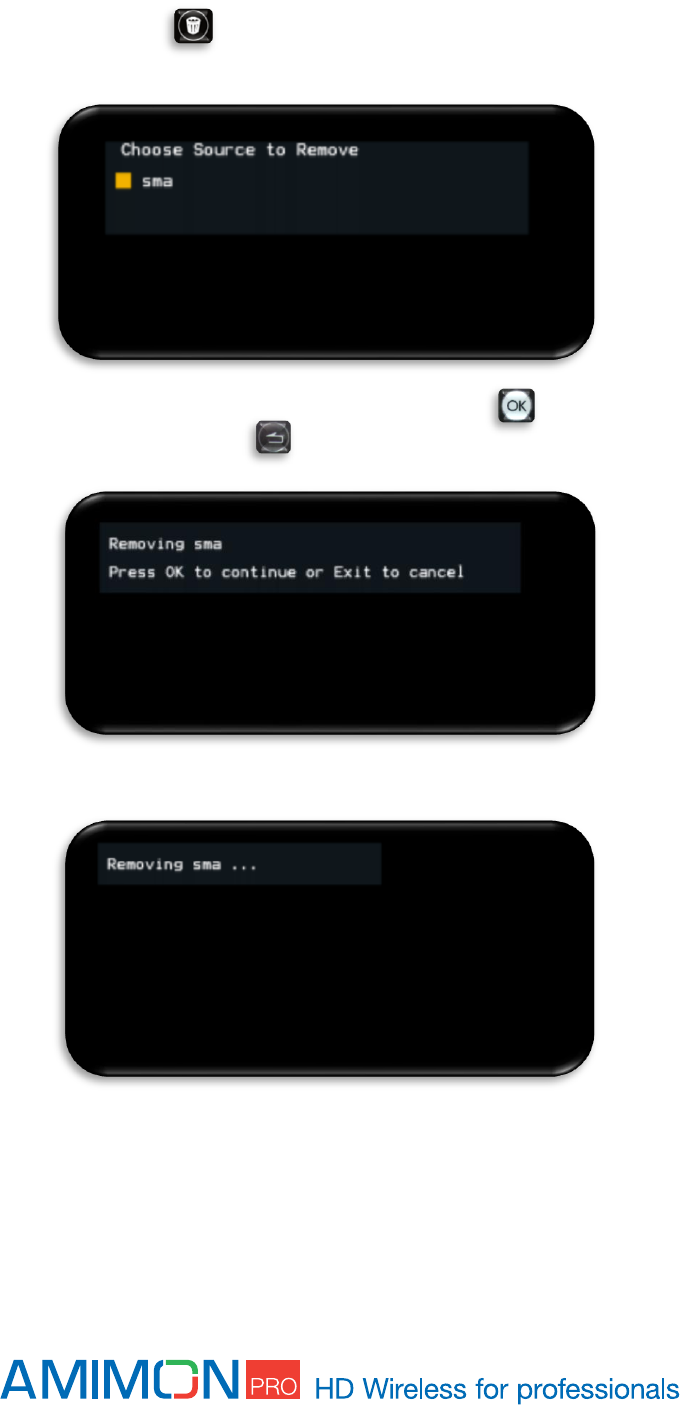
Unregistering transmitters
1. Power on the Amimon-AMN36254_PR2 receivers.
2. Use the remote control at the Amimon-AMN36254_PR2 receiver and
Press the “Delete” Hotkey button.
3. Select the source to be removed, using the up, down arrow buttons, and “OK” button.
4. Confirm removal of the selected source by pressing the “OK” button, or cancel the
selection by pressing the “Exit” button.
5. Wait 30 seconds for the removal process to be completed.
6. Transmitter removal is complete.

Switching between transmitters
1. In order to switch between video transmitters, press the “SOURCE” button and a
menu will appear
2. Choose the desired transmitter using the up, down arrows, and “OK” buttons.
*Note this is a Unicast product, the desired transmitter must be disconnected from any
another system before being chosen.
3. The existing video link will be lost and within 30 seconds, the new transmitter will connect and
new video link will be established.
Multi-system operation
SkyLink supports multisystem mode, i.e. several pairs of receivers and transmitters can work
simultaneously. It is recommended to keep the pairs at least 1 meter away from each other.
Link drop
Likely causes for this might be:
1. Exceeded Range
To re-establish link bring systems back in to range.
2. Reset
To re-establish link in case Tx/Rx have been reset, it is necessary to reset both sides. In Aerial
mode both systems must be within 30 meters of each other. In Multi-monitor mode the systems
must be within the operating range defined in the spec.
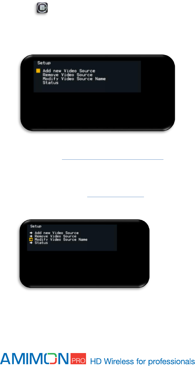
OSD - Menu
The Amimon-AMN36254_PR2 receiver generates an OSD-Menu (On-Screen Display).
This is used for adding/removing devices and presenting the link status and technical information.
OSD - Setup window
In order to open the Setup window Use the remote control at the Amimon-AMN36254_PR2 receiver
and Press the “Menu” Hotkey button.
The Setup window contains: Add new source, Remove source, Modify name source and Status
menus for technical information.
Adding new video Source
To add a new Video Source, refer to Registering a transmitter to a single receiver section.
Removing video Sources
In order to remove a source please refer to the Unregistering transmitter section.
Modify video source name

In order to modify the source name, follow the instructions below:
1. In order to modify the transmitter name press the “MENU” button to open the OSD
menu.
2. Choose the “Modify Video Source Name” option using the up and down arrows.
3. Press the “OK” button.
4. A list of all the registered transmitters will pop up.
5. Choose the source to rename using the “Up” and “Down” arrow buttons.
6. Press “OK” to select the source.
7. Choose the characters you wish to modify using the right and left buttons on the remote
control, and modify the name using the up, down and “OK” buttons.
8. Press “OK” to save the modified name.
Note: the transmitter name is modified on the receiver, so if the transmitter is registered to another
receiver, the original name of the transmitter will not change on that receiver.
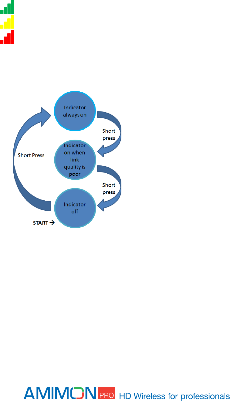
Link Quality Indicator
The link quality indicator gives the user an indication of link quality.
When enabled this indicator appears in the top left corner in three different colors, depending on the
quality of the link:
- Very good
- Reasonably good
- Poor
In order to enable the indicator the user must short press the link quality button on the Receiver during
link. With a series of short presses the user can switch between several indication modes as described
in the flow chart below:
Note that the link quality indication button on the receiver is used for registration as well. During link a
long press will generate the registration message on the monitor.
Before a link is established:
This button is used solely for the registration process. See Registration section for correct usage.
Technical Specifications
SPECIFICATION
DESCRIPTION
Video Resolution:
1080p/50, 1080p/60, 1080/59.94i, 1080/50i, 1080/29.97p, 1080/23.98p,
720/59.94p, 720/50p, 525i/59.94, 625i/50, 1080/24p.
Frequencies:
Non-DFS Frequencies :
5.170~ 5.250 GHz for EU
5.170 ~ 5.250 GHz and 5.735~5.815 GHz for US
DFS Frequencies (used only in Aerial mode):
5.250-5.330 GHz and 5.490 ~ 5.690 GHz for EU
5.250-5.330 GHz and 5.490 ~ 5.590 GHz and 5.650 ~ 5.690 GHz
for US
ISM Frequencies:
5.725 ~ 5.875 GHz for EU
Video Interface:
Tx: HDMI
Rx: SDI with automatic detection (SD,
HD and 3G) over 75 Ohm BNC.
Environment:
Operational - 0:40° C, 10%~90% humidity
Storage - 0:55° C, 10%~90% humidity
Range:
Up to 500m line of sight.
Delay
Less than 1 msec.
Product Regulation:
CE,FCC, RoHS, ESD +2Kv, , DFS
FCC ID
VQSAMNKHIN1
Specifications
Amimon - AMN35223_PB transmitter and Amimon-AMN36254_PR2 receiver
TRANSMITTER AMN35223
RECEIVER AMN36254
Video
Interface
HDMI male connector
SDI splitter
Option to connect external connector board
Audio
Over HDMI. Supports up to 2
channels.
Over SDI
Frequency
Control
Automatic
Automatic
Antenna
2 transmitting 1 Receiving
external using on-board RP SMA
Connectors
5 receiving 1 transmitting
Internal or external using on-board RP SMA
Connectors
Voltage
7-17 ±10%
7-17 V ±10%
Size
Without case: 90mm x W60mm x H
With case :
L130mm x W106mm x H
User Control
3 LEDs indicating Power, Video lock
and Network lock
USB connector for software update
Registration button
Reset button
2 Slide switches for mode selection
External host connector
UART
3 LEDs indicating Power, Video lock and
Network lock
USB connector for software update Hidden
button for registration
Reset button

Troubleshooting
Registration fails
Make sure both transmitter and receiver are powered on.
Make sure the power cable is continuous.
Make sure that pairing units are the only Amimon devices currently powered on.
Bring the transmitter and receiver closer together but no closer than 1 meter.
Keep the number of solid walls between the transmitter and receiver to a minimum.
No Signal on monitor
Make sure the receiver is powered on.
Make sure the monitor is powered on.
Make sure the receiver is properly connected to the monitor.
Make sure the monitor is set to display video from the right source (HD-SDI1, HD-SDI2, HD-
SDI3 etc.).
Reboot the receiver.
Unplug and then re-plug the HD-SDI cable between the receiver and the monitor.
Replace the HD-SDI cable.
Make sure the video resolution is supported by the monitor.
No video over the wireless link
Make sure the transmitter is properly connected to the source.
Make sure the source is powered on.
Unplug and then re-plug the transmitter to the source.
Abnormal Color or Noise on the monitor
Unplug and then re-plug the HD-SDI cable between the receiver and the monitor.
Unplug and then re-plug the HDMI cable between the transmitter and the source.
Bring the transmitter and receiver closer together but no closer than 1 meter.
Keep the number of solid walls between the transmitter and receiver to a minimum.
Power cycle the system.
No Audio
Check the mute and audio volume settings on the monitor.
Check the audio format setting on the source is incompatible with system. Change the source
to output PCM 2.0, DTS or Dolby Digital.
Make sure the pin #2 on the DIP switch is down.
IR Remote Control Malfunctions
Make sure the plastic cover of the battery is removed.
Make sure the remote control batteries are fully charged.

Make sure the IR receiver is connected to the Amimon-AMN36254_PR2 receiver.
Make sure there is a far enough distance between the IR receiver and any fluorescent lighting
or radiation interfering with the IR signals.

Other malfunctions
The receiver keeps outputting a “Searching…” message, and the NETWORK LED is
constantly blinks: It should take up to one minute to establish a wireless link. If the link was not
established within that time period, verify the transmitter is powered on and not connected to another
receiver.
The receiver is outputting “Connected to source name, Please Check Video Source”: Check
the HD-SDI connection between the transmitter and the video source.
The receiver displayed a connection failure message and outputs a “Wireless Off” message:
If there is more than one registered transmitter, and the receiver failed to connect to it within a minute
or two, the receiver will go into standby mode and shut down the RF. In order to connect to the
desired source, press on the “SOURCE” button and choose the desired source.
The NETWORK LED blinks rapidly and there is no display on the monitor: Power cycle the
unit. If the issue remains, the device might be faulty. Please contact Amimon support team.
Link cannot be established or poor video/Audio quality: Try to decrease the range between the
transmitter and the receiver or remove obstacles out of the way between the transmitter and receiver.
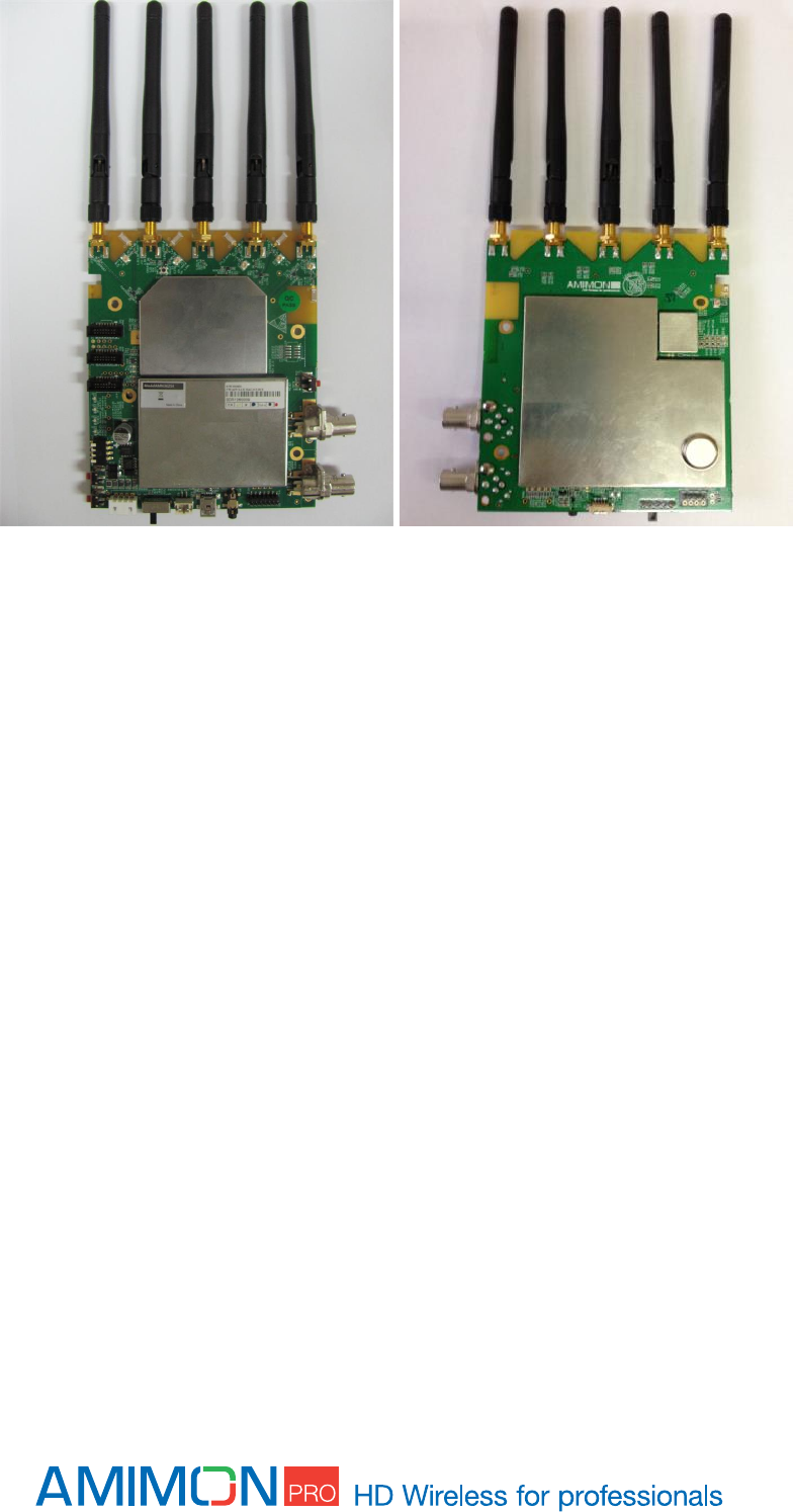
Appendix
Tx without enclosure
Rx without enclosure