Amimon AMNMGIN01 wireless video receiver module User Manual
Amimon Ltd. wireless video receiver module
Amimon >
User manual

AMN39203 (Maglan)
User/Installer Manual
An AMIMON Inc. Document
Copyright 2014
Version 1.0
www.amimon.com

Important Notice
AMIMON Ltd. reserves the right to make corrections, modifications, enhancements, improvements, and
other changes to its products and services at any time and to discontinue any product or service without
notice. Customers should obtain the latest relevant information before placing orders and should verify that
such information is current and complete. All products are sold subject to AMIMON's terms and conditions
of sale supplied at the time of order acknowledgment.
AMIMON warrants performance of its hardware products to the specifications applicable at the time of sale
in accordance with AMIMON's standard warranty. Testing and other quality control techniques are used to
the extent AMIMON deems necessary to support this warranty. Except where mandated by government
requirements, testing of all parameters of each product is not necessarily performed.
AMIMON assumes no liability for applications assistance or customer product design. Customers are
responsible for their products and applications using AMIMON components. To minimize the risks
associated with customer products and applications, customers should provide adequate design and
operating safeguards.
AMIMON does not warrant or represent that any license, either express or implied, is granted under any
AMIMON patent right, copyright, mask work right, or other AMIMON intellectual property right relating to
any combination, machine, or process in which AMIMON products or services are used. Information
published by AMIMON regarding third-party products or services does not constitute a license from
AMIMON to use such products or services or a warranty or endorsement thereof. Use of such information
may require a license from a third party under the patents or other intellectual property of the third party, or
a license from AMIMON under the patents or other intellectual property of AMIMON.
Reproduction of information in AMIMON data books or data sheets is permissible only if reproduction is
without alteration and is accompanied by all associated warranties, conditions, limitations, and notices.
Reproduction of this information with alteration is an unfair and deceptive business practice. AMIMON is
not responsible or liable for such altered documentation.
Resale of AMIMON products or services with statements different from or beyond the parameters stated by
AMIMON for that product or service voids all express and any implied warranties for the associated
AMIMON product or service and is an unfair and deceptive business practice. AMIMON is not responsible
or liable for any such statements.
All company and brand products and service names are trademarks or registered trademarks of their
respective holders.
Revision History
Version
Date
Description
1.0
June 29,2014
Initial Release

Table of Contents
Important Notice ........................................................ 2
Revision History ......................................................... 3
Table of Contents........................................................ 4
Safety Instructions ...................................................... 5
Introduction ............................................................... 6
1.1 Front view ..............................................................................................................7
1.2 Back view ...............................................................................................................7
LED behaviors ....................................................................................... 8
Interface Connector (J32) ...................................................................... 9
FCC Caution.............................................................. 12
S
Y
Z
0
1
0
M
Safety Instructions
When operating this equipment, read and follow all the instructions in this manual.
Do not open unit.
Do not block the air ventilation openings.
Use only accessories specified or recommended by Amimon.
When devices are switched on keep away at least 20 cm from your body.
Do not expose to moisture or excessive heat.
Keep away from water
Use the mains plug to disconnect the apparatus.
Clean with a dry cloth only.
Unplug this apparatus during lightning storms or when unused for long periods of time.
To reduce the risk of fire or electric shock, refer servicing to qualified service personnel.
Keep these instructions in a safe and accessible place for future use.
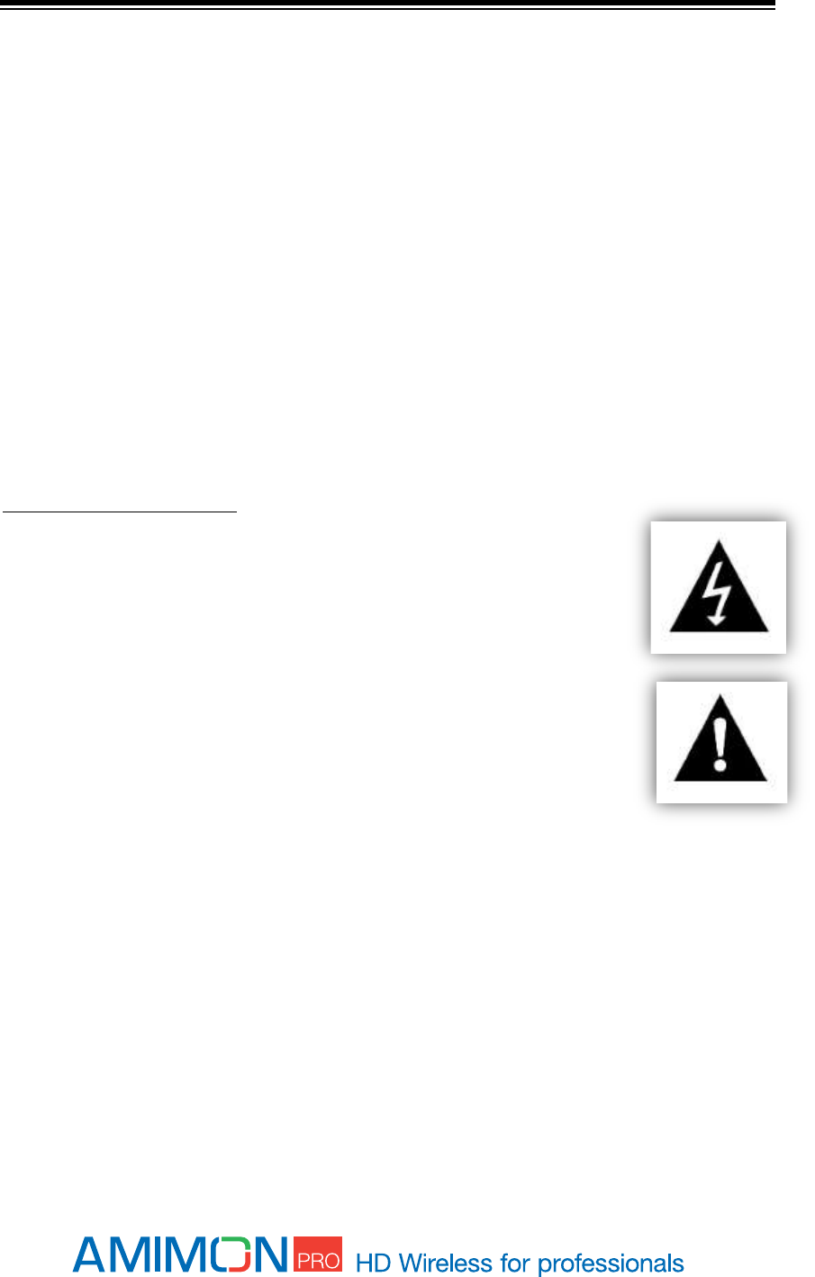
Explanation of graphical symbols:
High Voltage Sign: warns the user of the presence of uninsulated "dangerous
voltage" within the product enclosure, which may be of sufficient magnitude to
constitute a risk.
General Warning Sign: warns the user of the presence of important operating
and maintenance (servicing) instructions in the product manual.
Introduction
The AMN39203 is wireless A/V receiver board, which works at the 5GHz unlicensed band.
It is are based on AMIMON's WHDI Professional chipset that consist of the AMN2220 baseband
receiver and the MAXIM 2851 ICs, presents the ultimate solution for HDMI receiver of the WHDI
system. The perfect HDMI video, audio quality, the high robustness and the invisible latency of
the wireless system are unmatched by any other wireless technology and presents a true
alternative to cable. The WHDI system transmits uncompressed video and audio streams
wirelessly and thus simplifies and eliminates system issues, such as: lip-sync, large buffers and
other burdens like retransmissions or error propagation.
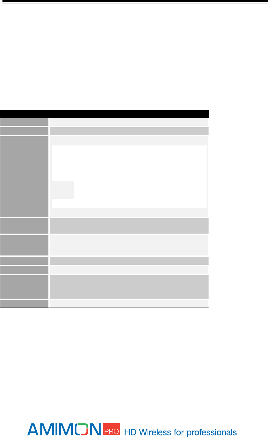
System Technical Specifications:
Table 1: Technical Specifications
Transmitter AMN35253
Video Interface:
Y-Cb-Cr
Audio:
Over I2S interface
Frequency
Control:
Non-DFS Frequencies :
5.170~ 5.250 GHz for EU
5.170 ~ 5.250 GHz and 5.735~5.825 GHz for US
DFS Frequencies (used only in Aerial mode):
5.250-5.330 GHz and 5.490 ~ 5.710 GHz for EU
5.250-5.330 GHz and 5.490 ~ 5.590 GHz and 5.650 ~
5.710 GHz for US
SRD Frequencies (EU):
5.725 ~ 5.875 GHz for EU
Antenna:
4 receiving + 1 transmitting/receiving
External using on-board RP SMA Connectors
Environment:
Operational - 0:40° C, 10%~90% humidity
Storage - 0:55° C, 10%~90% humidity
Voltage:
5V ±10%
Size:
L: 75mm x W: 80mm x H: 15mm
User Control:
3 LEDs indicating Power, Video lock and Network lock
Connector for software update; button for registration;
Reset button
FCC ID
VQSAMNMGIN01
1 PRODUCT DESCRIPTION
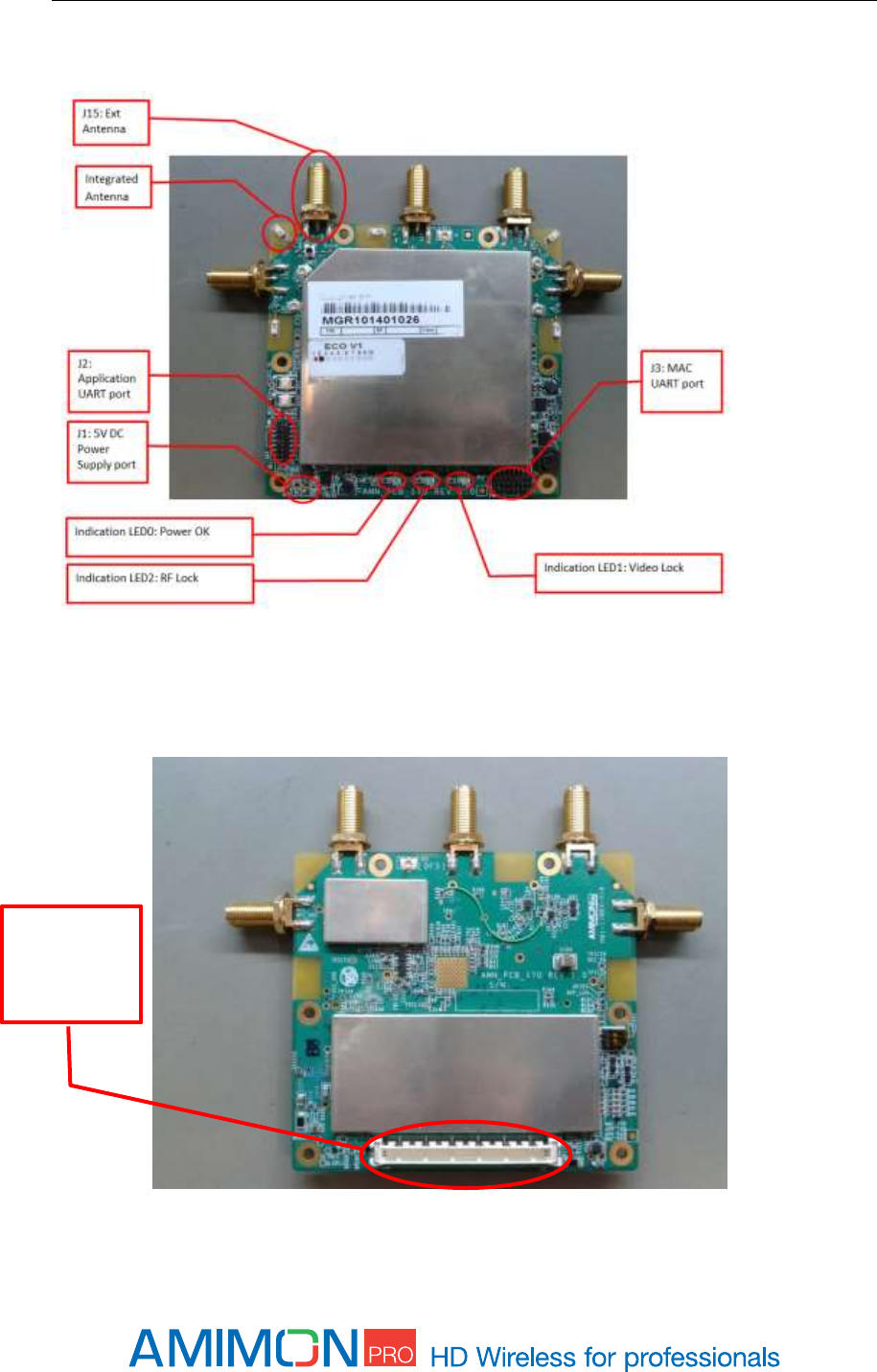
Front view
Figure 1 –Rx AMN39203 top-side
Back view
Figure 2 – Rx AMN39203 bottom side
J32:
Interface
connector
LED behaviors
Network LED
BLINKING MODE
DESCRIPTION
Solid
When a connection to Tx is established*/Link quality is good
Slow
Device is in listen mode/Link quality is reasonably good
Normal
During link setup mode/during registration
Fast
System Error (Video LED flashing as well)/Link quality is poor
*In Aerial mode even when Tx is out of range.
Video LED
BLINKING MODE
DESCRIPTION
Solid
Video signal is locked
Fast
System Error (Video LED flashing as well)
Power LED
BLINKING MODE
DESCRIPTION
Solid
Power is supplied

Interface Connector (J32)
The Interface connector J32 provides various interfaces to communicate with the AMN39203
MCU to configure video related parameters and settings, or receive the network status and
communication related parameters.
The following interface options are available:
- External Power Supply voltage (5VDC ±10%)
- Signal Ground
- Video YCbCr signal output
- I2S audion output interface
- I2C bus
- Indication output (Power, Network, Video Indications)
- Board attached ID pins
- UART
- USB
- SPI
Contact Amimon to request the complete pin allocation and functional description of the
interface board.
The communication through the interface board is provided by AMIMON’s API commands. A
guide for the API commands is available upon request.

2 PRODUCT INSTALLATION
The AMN39203 is referred as the main platform that comprises a wireless Video Display Unit (VDU). It
provides RGB video signal bus and I2S audio interface at its interface connector output. The source of the
video and audio is a compatible remote wireless Video Source Device (VSU). At common application, the
VSU is connected to a video source, and transmits the video over wireless to the VDU, which is connected
to the video monitor.
The AMN39203 is designed to be integrated with any compatible Video Interface Board (VIB), to provide a
complete wireless Video Display Unit.
At common application, the VIB shall provide standard video interface that can be connected to standard
video monitor. This video interface may be HDMI, HD-SDI or any other standard or custom video interface.
It is advised to verify compatibility of the VIB to the interface connector type, pin functionality, and signal
compatibility of the AMN39203 module, before initiating the installation.
At installation, make sure that the AMN39203 is firmly attached and secured to the VIB by proper
mechanical means.
Installation of AMN39203 must provide the adequate heat dissipation means, to provide the module
ambient temperature within the product operating conditions as specified.
3 SYSTEM SETUP
See ‘Product Description’ for port location described in this section.
1. Connect the Amimon-AMN39203 receiver to compatible Video Interface Board (VIB).
2. Connect the VIB to a video monitor through the supported video interface of the VIB.
3. Power ON the VIB according to its operating manual.
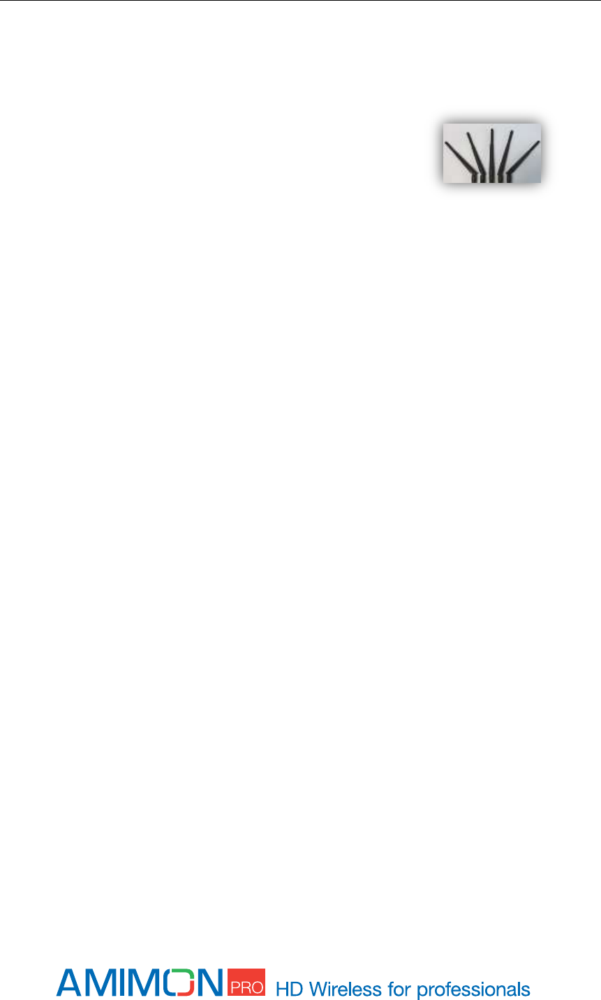
4. Set the Antenna orientation of the AMN39203:
It is recommended to separate the antennas to match the
picture. Receiving antennas should be oriented in the same
plane as the transmitting antenna.
Note: For maximal range
Keep line of sight between the transmitter and the receiver.
Avoid placing any obstacles besides the transmitter or the receiver.
Position both transmitter and receiver in an upwards position, for enhanced antennas
performance.
Mount the Amimon - AMN39203 module with proper air ventilation.
Bring the transmitter and receiver closer together while trying to maintain at least 1 meter
between them.

FCC Caution
Any changes or modifications not expressly approved by the responsible party could void the user's
authority to operate this equipment.
Notice:
This module in its final integration requires the end-product to continue to comply with DFS requirements.
A class II permissive change may be required for operation not already described in the FCC Grant filing.
OEM Labeling Requirements
Notice: The OEM of final integrator must ensure that FCC labeling requirements are met.
For a host using this module, if (1) the module’s FCC ID is not visible when installed in the host, or (2) if
the host is marketed so that end users do not have straightforward commonly used methods for access to
remove the module so that the FCC ID of the module is visible; then an additional permanent label
referring to the enclosed module should be used, with the following contents: Contains FCC ID:
.
The host OEM user manual must also contain clear instructions on how end users can find and/or access
the module and the FCC ID. The applicable usage is to be used as a wireless device, connected to the back
of a professional camera and transmitting live video, coming from BNC connectors
NOTE:
This equipment has been tested and found to comply with the limits for a Class B digital device, pursuant
to part 15 of the FCC Rules. These limits are designed to provide reasonable protection against harmful
interference in a residential installation. This equipment generates, uses and can radiate radio frequency
energy and, if not in-stalled and used in accordance with the instructions, may cause harmful interference
to radio communications. However, there is no guarantee that interference will not occur in a particular
installation.
FCC Radiation Exposure Statement
This equipment complies with FCC RF radiation exposure limits set forth for an uncontrolled environment.
This transmitter must not be co-located or operating in conjunction with any other antenna or transmitter.
This equipment complies with Part 15 of the FCC Rules. Operation is subject to the following two
conditions:
(1) This device may not cause harmful interference, and
(2) This device must accept any interference received, including interference that may cause
undesired operation.
THE ANTENNA USED FOR TRANSMISSION MUST BE INSTALLED TO PROVIDE A SEPARATION DISTANCE OF AT LEAST
20CM FROM ALL PERSONS AND MUST NOT BE CO-LOCATED OR OPERATING IN CONJUNCTION WITH ANY OTHER
ANTENNA OR TRANSMITTER.