Users Manual
Please read this user manual before you use this product, it contains all the notes and impor-
tant things regarding operating this product. In accordance with the safety precautions and
operating instructions listed on this user manual, our applies provided the product is handled
properly for its intended use, but may not apply to below cases:
● Repairs or product modification and alterations have been executed by unauthorized
personnel.
● The damages are caused by accidents including but not limited to lightning, fire, exposed
to rain or water,and moisture.
● Do not use provided power adapter with specific power voltage which are not compliant
with the rated voltage range in the attached label of the power adapter in package.
● The model label on the product has been modified or the warranty tag has been removed
by unauthorized personnel.
The high temperature in the process of operating the device
may cause the high risk of scalding.
To reduce the risks of electricity, do not remove or open the
cover. No user-serviceable parts are inside. Please return to
original factory for maintenance
Safety Precaution
● As connecting any equipment (such as any player or TV , etc.),
please turn off the power to the product before any operation is undertaken.
● Power outlet: To prevent electric shock or fire, short circuit, please make sure the type of
electrical plug used on the receiver's and transmitter's power cord are compliant with the
rated voltage range in the attached label of the power adapter in package.
● Power cord: Do not place any heavy articles above on the power cord. To avoid being
stepped on or pinched by heavy items, the power cord should not be located on the place
where people pass by frequently.
● Power overloading: Avoid overloading wall's electrical outlets and extension cord or other
multi-socket; otherwise could result in electric shock or fire.
● Lightning: For protection from lightning or when the product is left unattended for a long
period, please disconnect it from the power source.
● Please disconnect the power cord from the power outlet when you are not using the
receiver and transmitter, this will reduce the risk of electric shock or fire.
Danger: Be careful with electricity.
● This product should not be exposed to dripping or splashing. Do not place any object filled
with liquid on the product(eg. vases).
● To avoid electric shock, please do not block or stick anything on the air vent of product; do
not remove the cover or put the object just like pins, steel wire into the gap of the air vent.
● Please place the receiver/ transmitter on a flat with hard and stable surface.
● Ventilation: please do not block the air vents on the receiver/transmitter or place any heavy
object on top of them . Blocking the air flow can damage the product itself. Please make
sure that there is adequate ventilation distance between the receiver and TV, and also put
the product away from direct sunlight or any source of heat.
● Water Exposure: To reduce the risk of electric shock or fire , please do not expose the
receiver/transmitter to rain or moisture.
● We assume no responsibility for any damage or result caused by using other adapters instead
of our standard adapters
Important Information
Warning
● Although the product has provided the function of data encryption when transmitting,
you still need to pay attention to deliberate signal interception. There will be the
Possibility of a third party intentionally intercept the transmission signal since the product
adopt wireless communication. Please do not use the product on confidential and important
communications, or life-related communications The main concern is that the content of
wireless communication might be received by the third party's wireless devices deliberately
or accidentally.
● The impact of radio waves (such as the following environment may cause the abnormal
audio and video(blocked image, noise ...etc.).
1 ) Transmit near the wall which is hard for the radio waves to get through.
2 ) Quite close to the refrigerator, metal fitment and appliances, or next to the crowded
situation.
● This product has been tested and manufactured to comply with national electrical safety
rules, however, there will be noise caused by the interference with other machines in rare
cases. If the interference is happened, please keep a certain distance away from other
machines.
● The product is susceptible to interference from 5GHz wireless local area network or other
wireless devices.
● Optimal range between transmitter and receiver is between 1 meter and 30 meters within
line of sight indoor.
● Please do not set up the transmitter and receiver in metal shelf, or it will hinder the
wireless communications.
● 1080P/60 Hz Wireless transmitting.
● It will take 15-20 seconds to boot the system before wireless communication start, the
media receiver can not be operated during this time.
Special Notice
Danger!
High voltage
Beware of
hot surfaces!
Caution!
Please use our standard power adapter.Detailed information
refer to the rated voltage range showed on the label at
the back of package's power adapter.
Please
This equipment complies with FCC radiation exposure limits set forth for an uncontrolled
● FCC Radiation Exposure Statement:
environment .This equipment should be installed and operated with minimum distance 20cm
between the radiator& your body.
Keep the product away from the body 20cm.
●
● Use only indoor.
● No enclosure provided, need add a complete 5VB enclosure.
2. Features:
1.Uncompressed and uncompromised FHD video quality
2.Supports 20 and 40 MHz channels for supreme video quality and high rate video/audio signals
3. Supports WHDI、Unicast、Broadcast
4. Supports HDMI、SDI output device(Need connect ES001 to use)
5. Strong 256-bit/128-bit AES based encryption
6. Supports MIMO technology
7. Supports OSD display WHDI 1.0 compliance, including HDCP 2.0
3. Performance parameters:
Number Unit Specification
Item
5.15~5.25, 5.25~5.35, 5.47~5.725,
1Transmitter&Receiver Frequency GHZ
5.725~5.825 (GHz)
2MIMO
RF Communication Systems
3Modulation Mode OFDM
4Frequency Stability PPM ±20
5Operating Bandwidth MHZ 40
6Typical Transmit Power dBm 15(MAX)
7Receiver Sensitivity dBm -70
8System Delay ms ≤1(Video No Compression)
9Channel 1 & 5
Transmit Channel&Receive Channel
10 HD Video System
HD: 480i, 480p, 576i, 576p, 720p, 1080i, 1080p
Panel: 854x800, 1280x768, 1366x768, 1920x1080
PC: VGA (640x480), SVGA (800x600),
XGA (1024x768),
11 HD Video Encryption HDCP 1.2
12 Multi-path Transmission Distance m50
13
14
15
16
17
18
Consumption Current mA 820±10%
Power Supply VDC 3.3±5%
Operation Temperature ℃0℃ - + 40℃
Storage Temperature ℃-20℃ - + 60℃
Operation Humidity RH 15% - 85%
Dimensions mm 144.92X105X1.78
1.
AMN32200-IR Block DiagramAMN32200-IR Block DiagramAMN32200-IR Block Diagram
ts and 40 MHts 40 MH
4.
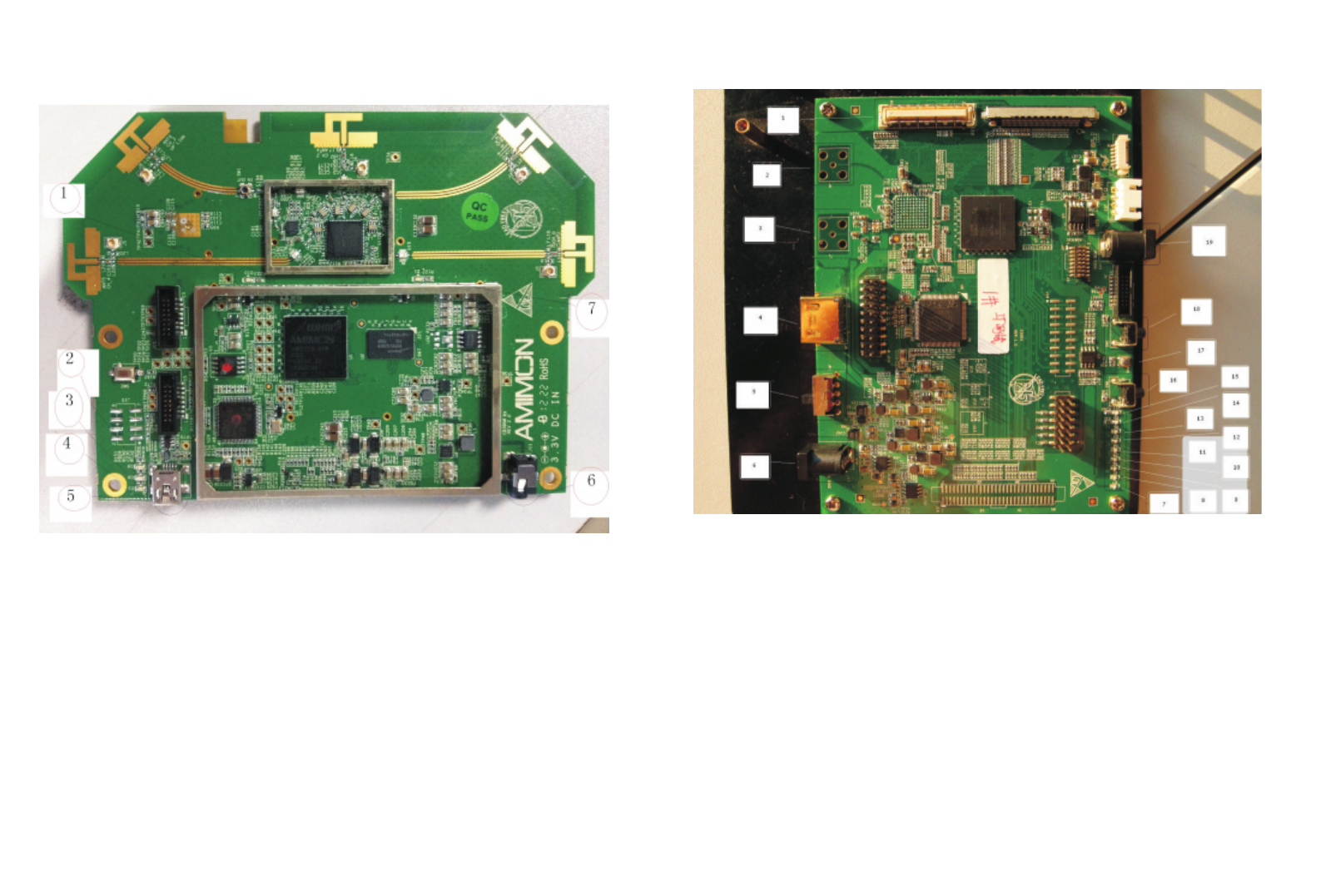
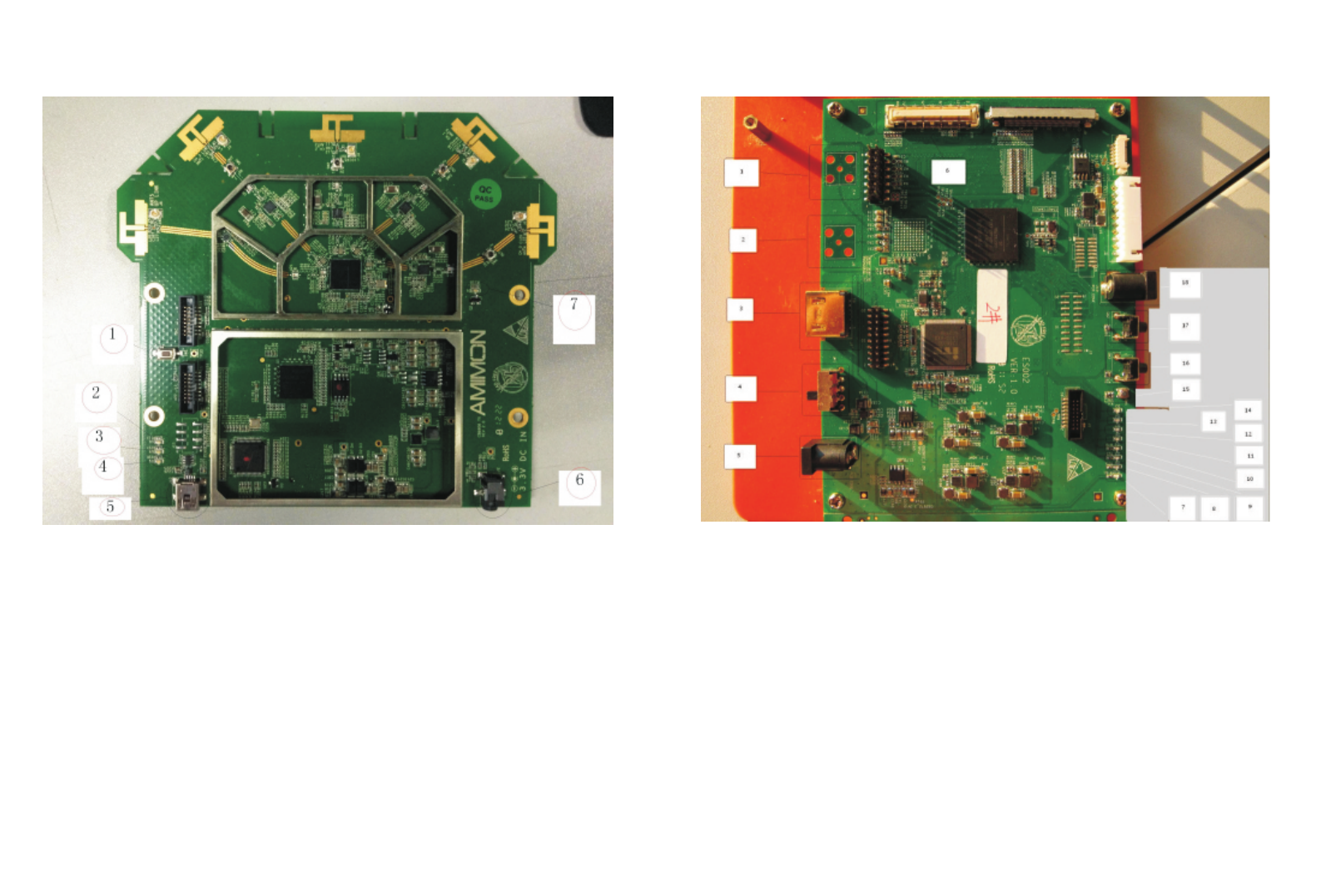
Interface and Button definition:
1. Blue LED: BB I/O Work indicator
2. Blue LED: Video connection indicator
3. Blue LED: Wireless connection indicator
4. Blue LED: ARM working indicator
5. USB Interface
6. DC IN:3.3V Power input
7. Blue LED: RF IC Work indicator
5.ES001 Interface and Button definition:
1. 80PIN Connector:Connected with the AMN32200-IR
4. HDMI Interface: HDMI output
5. Toggle switch:Power switch
6. DC IN: 5V Power input
7. Blue LED:YCbC 444 Indicator
8. Blue LED:SDI Signal Lock Indicator
9. Blue LED:SDI Signal bit error rate indicator
10. Blue LED:YCbCr Input indicator
11. Blue LED:YCbCr 422 indicator
12. Blue LED:SDI Signal input indicator
13. Blue LED: Not defined
14. Blue LED:5V Power indicator
15. Blue LED:FLAG1 Power indicator
16. Tact Switch:Not defined
17. Tact Switch:System reset button
19. DC IN: 5V Power input
2. BNC(75Ω):BNC cable to connect the
output of the SDI signal
3. BNC(75Ω):BNC cable to connect the SDI
signal loop output
18. Tact Switch:HDMI and SDI Output select
buttons, Default HDMI
AMN32200-IR Product appearance and Interface definitionAMN32200-IR Product appearance and Interface definitionAMN32200-IR Product appearance and Interface definitionAMN32200-IR Product appearance and Interface definitionAMN32200-IR Product appearance and Interface definition
2. Features:
1.Uncompressed and uncompromised FHD video quality
2.Supports 20 and 40 MHz channels for supreme video quality and high rate video/audio signals
3. Supports WHDI、Unicast、Broadcast
4. Supports HDMI SDI output device(Need connect ES002 to use)
5. Strong 256-bit/128-bit AES based encryption
6. Supports MIMO technology
7. Supports OSD display WHDI 1.0 compliance, including HDCP 2.0
3. Performance parameters:
Number Unit Specification
Item
5.15~5.25, 5.25~5.35, 5.47~5.725,
1Transmitter&Receiver Frequency GHZ
5.725~5.825 (GHz)
2MIMO
RF Communication Systems
3Modulation Mode OFDM
4Frequency Stability PPM ±20
5Operating Bandwidth MHZ 40
6Typical Transmit Power dBm 12(MAX)
7Receiver Sensitivity dBm -70
8System Delay ms ≤1(Video No Compression)
9Channel 4 & 1
Transmit Channel&Receive Channel
10 HD Video System
HD: 480i, 480p, 576i, 576p, 720p, 1080i, 1080p
Panel: 854x800, 1280x768, 1366x768, 1920x1080
PC: VGA (640x480), SVGA (800x600),
XGA (1024x768),
11 HD Video Encryption HDCP 1.2
12 Multi-path Transmission Distance m50
13
14
15
16
17
18
Consumption Current mA 360±10%
Power Supply VDC 3.3±5%
Operation Temperature ℃0℃ - + 40℃
Storage Temperature ℃-20℃ - + 60℃
Operation Humidity RH 15% - 85%
Dimensions mm 144.92X130X1.78
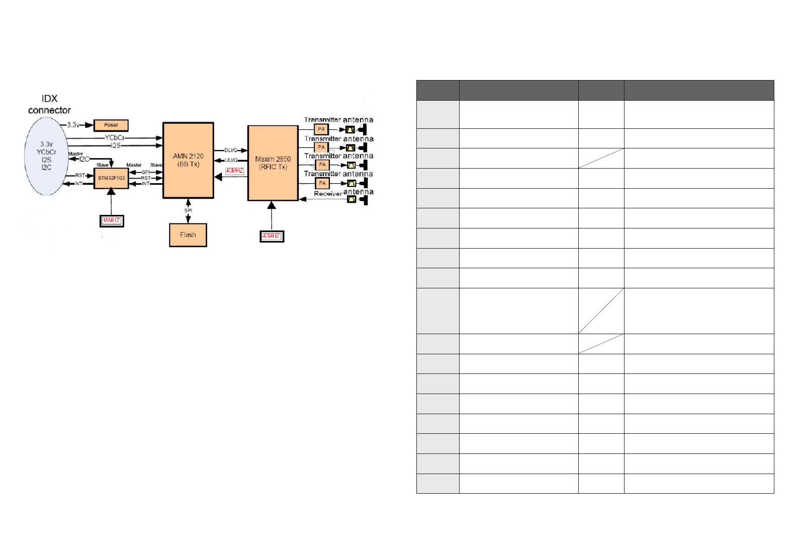
1. AMN31200-IR Block Diagram1. AMN31200-IR Block Diagram1. AMN31200-IR Block Diagram1. AMN31200-IR Block Diagram1. AMN31200-IR Block Diagram
ts 40 MH
Interface and Button definition:
1. Tact Switch:System reset button
2. Blue LED:ARM working indicator
3. Blue LED: Wireless connection indicator
4. Blue LED: Video connection indicator
5.USB Interface
6.DC IN:3.3V Power input
7. Blue LED: RFIC Work indicator
5.ES002 Interface and Button definition:
3. HDMI Interface: HDMI input
4. Toggle switch:Power switch
5. DC IN: 5V Power input
6. 80PIN Connector:Connected with the AMN-31200-IR
7. Blue LED:5V Power indicator
8. Blue LED:5V Power indicator
9. Blue LED:HDMI Signal Lock Indicator
10. Blue LED:SDI Signal Lock Indicator
11. Blue LED:YCbC 444 Indicator
12. Blue LED:YCbCr 422 Indicator
13. Blue LED:YCbCr Output Indicator
14. Blue LED:SDI Signal output indicator
15. Tact Switch:System reset button
16. Tact Switch:Not defined
18. DC IN: 5V Power input
1. BNC(75Ω):BNC cable to connect the
output of the SDI signal
2. BNC(75Ω):BNC cable to connect the
output of the SDI signal
17. Tact Switch:HDMI and SDI Output select
buttons, Default HDMI
4. AMN31200-IR Product appearance and Interface definition4. AMN31200-IR Product appearance and Interface definition4. AMN31200-IR Product appearance and Interface definition4. AMN31200-IR Product appearance and Interface definition4. AMN31200-IR Product appearance and Interface definition4. AMN31200-IR Product appearance and Interface definition

Under Industry Canada regulations, this radio transmitter may only
operate using an antenna of a type and maximum (or lesser) gain
approved for the transmitter by Industry Canada. To reduce potential
radio interference to other users, the antenna type and its gain should
be so chosen that , the equivalent isotropically radiated power (e.i.r.p.)
is not more than that necessary for successful communication.
This device complies with Industry Canada licence-exempt RSS standard(s).
Operation is subject to the following two conditions:
(1) this device may not cause interference, and
(2) this device must accept any interference,including interference that may cause
undesired operation of the device.
IC Warning :
FCC Radiation Exposure Statement
Caution!
The manufacturer is not responsible for any radio or TV interference caused by
unauthorized modifications to this equipment. Such modifications could void the
user authority to operate the equipment.
This equipment complies with FCC RF radiation exposure limits set forth for an
uncontrolled environment. This transmitter must not be co-located or operating
in conjunction with any other antenna or transmitter.
This equipment complies with Part 15 of the FCC Rules.Operation is subject to
the following two conditions:
(1) This device may not cause harmful interference, and
(2) This device must accept any interference received, including interference
that may cause undesired operation.
FCC Caution :
Any changes or modifications not expressly approved by the responsible party could void the user's
authority to operate this equipment.
Notice:
This module in its final integration requires the end-product to continue to comply with DFS requirements. A Class II
Permissive Change may be required for operation not already described in the FCC Grant filing.
OEM Labeling Requirements
NOTICE: The OEM or final integrator must ensure that FCC labeling requirements are met. This includes an additional label
on the outside of the final product housing with the following contents:
Company Name
MODEL:
Contains Model: AMN31200-IR, FCC ID: VOSCB890802120528
This device complies with Part 15 of the FCC Rules. Operation is subject to the following two conditions: (1) This device
may not cause harmful interferences, and (2) this device must accept any interference received, including interference
that may cause undesired operation.
The applicable usage is to be used as a wireless device, connected to the back of a professional camera using V lock
connectors, and transmitting live video, coming from BNC connectors, with less than 1msec delay.
Company Name
MODEL:
Contains Model: AMN32200-IR, FCC ID: VOSCB390802120528
This device complies with Part 15 of the FCC Rules. Operation is subject to the following two conditions: (1) This device
may not cause harmful interferences, and (2) this device must accept any interference received, including interference
that may cause undesired operation.