Ampeg Svt Gs Users Manual
Gene Simmons Punisher Bass Amplifier to the manual a854ad47-b7c5-4979-8103-9a898c16e152
2015-02-05
: Ampeg Ampeg-Svt-Gs-Users-Manual-508684 ampeg-svt-gs-users-manual-508684 ampeg pdf
Open the PDF directly: View PDF ![]() .
.
Page Count: 8
Owner's Guide
for the
Made in the U.S.A. by
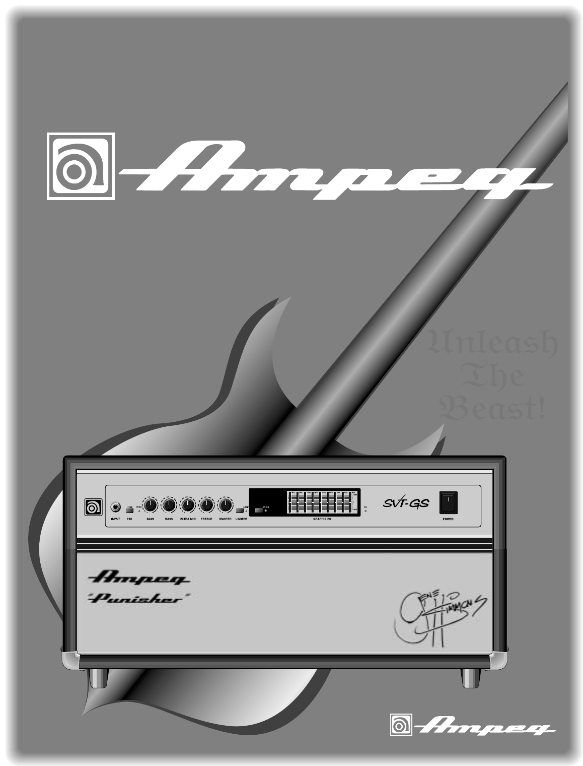
SVT-GS Gene Simmons Punisher
Bass Amplifier

SVT-GS Gene Simmons Punisher
2
Table of Contents
Introduction . . . . . . . . . . . . . . . . . . . . . . . . . . . . . .2
Features . . . . . . . . . . . . . . . . . . . . . . . . . . . . . . . .2
Important Safeguards and Precautions . . . . . . . . . .3
The Front Panel Controls and Their Use . . . . . . . .4
The Rear Panel . . . . . . . . . . . . . . . . . . . . . . . . . . .5
Some Suggested Settings . . . . . . . . . . . . . . . . . . .6
Troubleshooting . . . . . . . . . . . . . . . . . . . . . . . . . . .7
System Block Diagram . . . . . . . . . . . . . . . . . . . . . .7
Tech Specs . . . . . . . . . . . . . . . . . . . . . . .back cover
First of all, thank you for making what could be one of the best choices you could ever make concerning your
musical career – choosing one of the best bass amps available, the Ampeg SVT-GS Gene Simmons Punisher.
This powerhouse of an amplifier offers you many outstanding features: 350 watts of throbbing bass energy, total
tone control, rugged construction, and the seal of approval of Mr. Gene Simmons himself!
In the world of high performance bass amps, Ampeg’s SVT amplifiers stand alone. In true Ampeg tradition,
the SVT-GS Gene Simmons Punisher offers you more power, performance and flexibility than any other bass
amp in its class. Below are some of the outstanding features of your new amplifier; features which set it (and
you) apart from the competition!
•9-BAND GRAPHIC EQ: Use as a “second channel” for bass solos, or to shape your sound to your
own exacting standards
•BALANCED LINE OUTPUT: XLR with independent level control switch to patch into house con-
soles, mixing boards, or external power amplifiers
• EFFECTS LOOP: For increased intensity and quieter operation of external effects
• POWER AMP IN and PREAMP OUT: Allows direct access into the power amp and a signal tap
from the preamp section for even greater versatility
• GENE SIMMONS PUNISHER GRAPHICS: Inspired by one of Gene’s “deadly weapons”
• CLASSIC SVT SOUND AND PERFORMANCE: Proudly Made In America!
An introduction To Your Ampeg
SVT-GS Gene Simmons Punisher Bass Amplifier
Features
SVT-GS Gene Simmons Punisher
3
Important Safeguards and Precautions
All Ampeg products are designed for continuous safe operation, as long as common sense is used and
steps are taken to help avoid certain problems. Abiding by the following rules can help prevent damage to
your amplifier, yourself and others.
•The amplifier is equipped with a three-pronged AC power cord. To reduce the risk of electrical shock,
NEVER remove or otherwise attempt to defeat the ground pin of the power cord.
•Connect the amplifier ONLY to a properly grounded AC outlet of the proper voltage for your amp.
•Avoid sudden temperature extremes, rain and moisture. Also, avoid sudden and intense impact. (If
the unit has been subjected to any of the preceding abuses, have it looked at by an authorized ser-
vice center.)
•NEVER set the amplifier on a support that might give out under its weight.
•Always keep the total speaker impedance at or above the rated load.
•Unplug the amplifier before cleaning it. NEVER spray liquid cleaners onto the amplifier. Wipe it with
a slightly dampened, lint-free cloth to remove dirt and film.
•Don’t use the amplifier if it has sustained damage to the chassis, controls, or power cord. Refer the
unit to an authorized service center for inspection.
•Amplifiers capable of producing high volume levels are also capable of inflicting permanent hearing
loss or damage, if the exposure to such levels is prolonged. Such damage is progressive and irre-
versible!
CAUTION
RISK OF ELECTRIC SHOCK
DO NOT OPEN
CAUTION: TO REDUCE THE RISK OF ELECTRIC SHOCK,
DO NOT REMOVE COVER.
NO USER-SERVICEABLE PARTS INSIDE.
REFER SERVICING TO QUALIFIED SERVICE PERSONNEL.
ATTENTION
RISQUE D'ELECTROCUTION
NE PAS OUVRIR
ATTENTION: POUR REDUIRE D'ELECTROCUTION NE PAS
ENLEVER LE COUVERCLE. AUCUNE PIECE INTERNE N'EST REPRABLE
PAR L'UTILISATEUR. POUR TOUTE REPARATION, S'ADRESSER A UN
TECHNICIEN QUALIFIE.
VORSICHT
ELEKTRISCHE SCHLAGGEFAHR
NICHT OFFENEN
VORSICHT: ZUR MINIMIERUNG ELEKTRISCHER SCHLAGGEFAHR NICHT
DEN DECKEL ABENHMEN. INTERNE TEILE KONNEN NICHT VOM
BENUTZER GEWARTET WERDEN. DIE WARTUNG IS QUALIFIZIERTEM
WARTUNGSPERSONAL ZU UBERLASSEN.
THIS EQUIPMENT HAS BEEN DESIGNED AND ENGINEERED TO PROVIDE SAFE AND RELIABLE OPERATION. IN ORDER TO PROLONG THE LIFE OF THE UNIT AND PREVENT ACCIDEN-
TAL DAMAGES OR INJURY, PLEASE FOLLOW THESE PRECAUTIONARY GUIDELINES:
WARNING: TO REDUCE THE RISK OF ELECTRIC SHOCK, DO NOT OPEN CHASSIS; DO NOT DEFEAT OR REMOVE THE GROUND PIN OF THE POWER CORD; CONNECT ONLY TO A PROP-
ERLY GROUNDED AC POWER OUTLET.
CAUTION: TO REDUCE THE RISK OF FIRE OR ELECTRIC SHOCK, DO NOT EXPOSE THIS EQUIPMENT TO RAIN OR MOISTURE.
CAUTION: NO USER-SERVICEABLE PARTS INSIDE. REFER SERVICING TO QUALIFIED SERVICE PERSONNEL.
CAUTION: OUR AMPLIFIERS ARE CAPABLE OF PRODUCING HIGH SOUND PRESSURE LEVELS. CONTINUED EXPOSURE TO HIGH SOUND PRESSURE LEVELS CAN CAUSE PERMANENT
HEARING IMPAIRMENT OR LOSS. USER CAUTION IS ADVISED AND EAR PROTECTION IS RECOMMENDED IF UNIT IS OPERATED AT HIGH VOLUME. The chart below shows the U.S.
Government Occupational Safety and Health Administration (OSHA) regulations which were in effect at the time of this publication for permissible noise exposure, per 29CRF1910, Table G-16.
According to OSHA, any exposure in excess of those listed above could result in some hearing loss.
"IT IS NECESSARY FOR THE USER TO REFER TO THE INSTRUCTION MANUAL"
"REFERREZ-VOUS AU MANUAL D'UTILISATION"
"UNBEDINGT IN DER BEDIENUNGSANLEITUNG NACHSCHLAGEN"
EXPLANATION OF
GRAPHICAL SYMBOLS:
"DANGEROUS VOLTAGE"
"DANGER HAUTE TENSION"
"GEFAHLICHE SPANNUNG"
==
SOUND LEVEL dBA DURATION PER DAY
SLOW RESPONSE IN HOURS
90 8
92 6
95 4
97 3
100 2
SOUND LEVEL dBA DURATION PER DAY
SLOW RESPONSE IN HOURS
102 1-1/2
105 1
110 1/2
115 1/4 or less
SVT-GS Gene Simmons Punisher
4
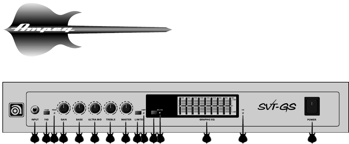
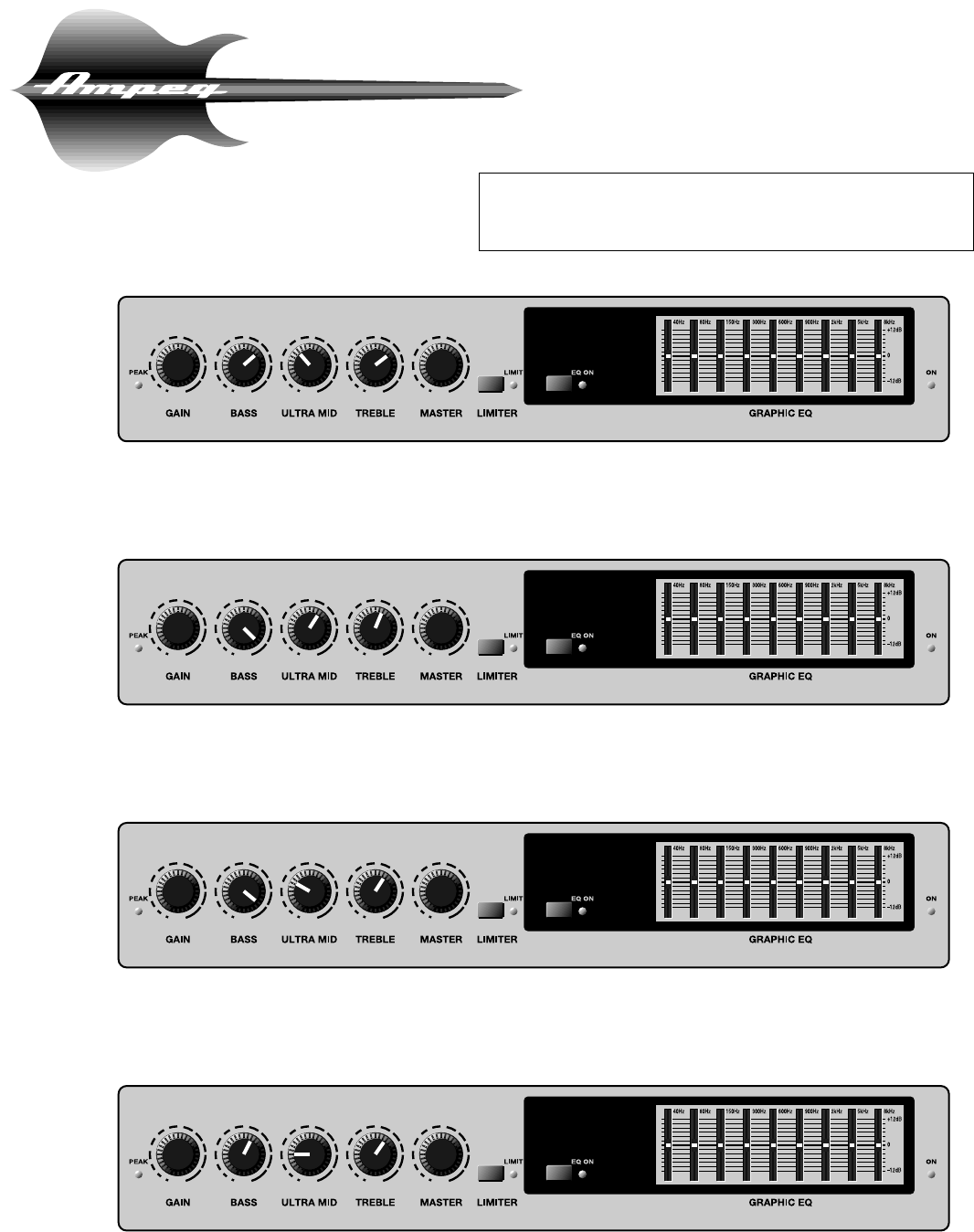
The Front Panel Controls and Their Use
4 5 6 7 8 103 12 13 14 1521 9 11
1. INPUT: Connect your bass here
using a standard shielded instrument
cable.
2. 15dB PAD: When engaged, this
switch cuts the input signal level by
15dB, allowing you to set the Gain
control (#4) for the best signal to noise
ratio. (If your bass has high-output
pickups or active electronics, you
should use the Pad.)
3. PEAK LED: This LED lights when-
ever any preamp stage is near clip-
ping. Adjust the Gain control (#4) until
a strong signal from your bass causes
this LED to flicker.
4. GAIN: This serves as the input level
control for the amplifier. For the best
signal to noise ratio, set this control so
the Peak LED (#3) flashes when you
hit your strings hard.
NOTE: If the Peak LED stays on with
the Gain at a low setting, use the 15dB
pad (#2) to cut the input signal, then
readjust the Gain.
5. BASS: The primary low frequency
control. This knob allows for a range of
8dB of cut or boost at 50Hz.
6. ULTRA-MID: The primary midrange
control. Rotate the knob to the left of
center for a “contoured” sound (more
distant, less midrange output) or to the
right of center for a sound which really
cuts through.
7. TREBLE: The primary high frequen-
cy control. This knob allows for a range
of 12dB boost or 19dB of cut at 5kHz.
8. MASTER: Set the overall output
level of the amplifier with this control.
The Effects Loop and Balanced Out
(#22-26) are not affected by the Master
control.
9. LIMITER SWITCH: The amplifier
uses an internal Optocoupler Limiter to
help keep the power amp’s output
“clean” at extreme volume levels. (All
amplifiers may begin to clip their out-
put signals as they approach maxi-
mum output levels, resulting in poten-
tially damaging distortion.) To engage
the Limiter, press in the Limit switch.
Playing at full power with the Limiter off
will give you increased output power,
but the sound may be distorted. Use
discretion when playing without the
Limiter.
10. LIMIT LED: This LED will flash any
time the internal limiter circuit is called
upon to keep the amplifier’s output sig-
nal clean. This shows that the amplifi-
er is nearing full output and the limiter
is keeping it from clipping the output
signal.
11. EQ ON SWITCH: Press this switch
IN to activate the Graphic EQ.
12. EQ ON LED: This LED lights when
the Graphic EQ is active.
13. GRAPHIC EQ: These slide con-
trols allow you to adjust the output of
the frequencies shown above each
control. The center position of each
control is flat (no boost or cut).
14. POWER ON LED: This LED lights
when the POWER switch (#15) is ON.
15. POWER SWITCH: This heavy-
duty rocker switch applies the power to
the amplifier: the amp is ON in the up
position, OFF in the down position.
SVT-GS Gene Simmons Punisher
5
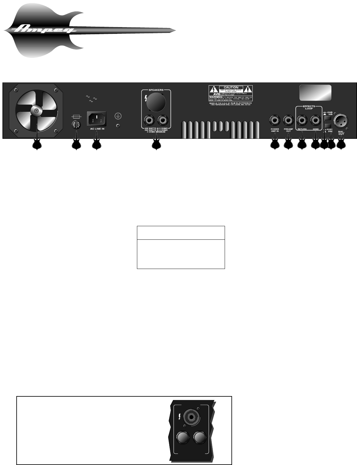
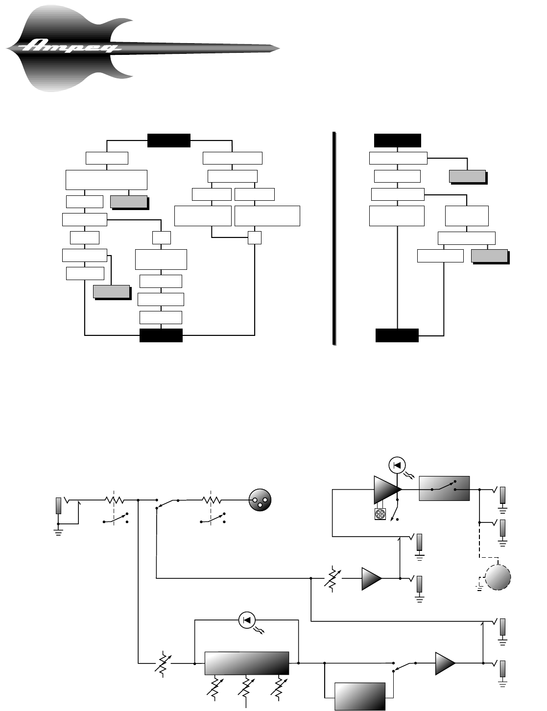
The Rear Panel
115VAC, 60Hz: T10A SLO BLO
100/115VAC, 50/60Hz: T8A SLO BLO
230VAC, 50/60Hz: T4A SLO BLO
MODEL:
SERIAL:
LINE: V ~ Hz
WATTS: MAX
SVT-GS
SVTGS126902U
120 60
16 17 18 19 20 21 22 25 262423
16. FAN: This temperature controlled,
variable speed fan draws cool air into
the amplifier, forcing heat out through
the exhaust vents (also on the rear
panel, between the speaker jacks and
the power amp in jack). Never block the
vent holes or the fan openings.
NOTE: It is not uncommon for the fan to
remain off when the amplifier is first
powered up.
17. FUSE: This protects the unit from
damage due to overload conditions or
power line surges. If the fuse blows,
replace it only with the same size and
type.
18. AC LINE IN: Firmly plug the sup-
plied AC power cord into this socket,
pushing it in until it is fully seated. Plug
the male end of the cord into a ground-
ed AC outlet. DO NOT DEFEAT THE
GROUND PRONG OF THE AC PLUG!
19. SPEAKER OUTPUTS: Use these
jacks to connect the amplifier to your
speaker(s) using cables terminated with
1/4” plugs. Always use high-quality
speaker cables for these connections.
NOTE: When connecting multiple
speaker cabinets to the amplifier,
keep the overall impedance at or
above four ohms! The following chart
shows the total impedance load when
connecting speaker cabinets in parallel:
20. POWER AMP IN: This mono jack
allows you to feed the preamp output of
another amplifier to the input of the
internal power amp. This disconnects
the SVT’s preamp.
21. PREAMP OUT: A post-EQ signal
may be taken from this jack to be sent
to the house mixing board, recording
console or external power amplifier.
22. EFFECTS RETURN: To use an
external effects device, connect the
OUTPUT of the device to the Return
jack using a shielded cable. This feeds
the processed signal into the amp’s
Master section.
23. EFFECTS SEND: Connect the out-
put from the Send jack to the INPUT of
your effects using shielded cable. This
sends a post-EQ signal to your effects.
24. -20dB SWITCH : This control
adjusts the output level at the Balanced
Line Output jack (#26). The control
works independently from the front
panel Master control. Pushing the
switch in activates the -20dB pad,
allowing use of microphone inputs on a
mixer without overdriving the inputs.
25. PRE/POST SWITCH: You can
select either Pre or Post EQ for the sig-
nal at the Balanced Out jack (#26) with
this switch. With the switch in the OUT
position, the signal at the jacks will be
Pre-EQ. This is a direct output not
affected by any EQ or boost settings.
With the switch in, the signal is Post-EQ
and is controlled and modified by the
tone controls, Graphic EQ, and Effects
Loop.
26. BALANCED OUTPUT: This XLR-
type connector supplies a balanced
preamp output signal for connecting to
a house mixing board, recording con-
sole or external amplifiers with bal-
anced inputs. The signal can be set to
Pre or Post EQ by the back panel
Pre/Post switch (#25). The level can be
adjusted for either mic or line type
inputs using the -20dB switch (#24).
Cabinet # of Total
Impedance Cabs Impedance
8Ω24Ω
16Ω28Ω
16Ω44Ω
SPEAKERS
200W @ 8 OHMS
350W @ 4 OHMS
4 OHMS MINIMUM
IMPORTANT NOTE ABOUT CERTAIN EXPORT
UNITS: In some areas 1/4” speaker jacks are not
acceptable for use on amplifiers capable of high out-
put power levels. For this reason the Speaker jacks
on your amplifier may resemble the illustration to the
right. Connect the amplifier to your speaker(s) using
cables rated for very high output power, terminated
with the appropriate connectors.
SVT-GS Gene Simmons Punisher
6
Some Suggested Settings
JAZZ:
ROCK:
COUNTRY:
FUNK “POPPING:”
The setting of the Gain and Master controls depend on your bass, on your
playing style, and on how loud you want it! The Graphic EQ can be used
to compensate for room acoustics, to “fine tune” your sound, and as a
“second channel” to be kicked in when needed for soloes and riffs.
SVT-GS Gene Simmons Punisher
7
Troubleshooting
In the unlikely event that your SVT-GS Gene Simmons Punisher should stop working properly (or just stop working), take
a few minutes to troubleshoot it before you call for service. You can save yourself a lot of time and sometimes money by
doing it yourself, and often the cure for the problem is something quite simple.
If the problem isn’t covered above, or if the steps led you here, then contact your Ampeg dealer for service informa-
tion. Also, you should refer your amp for servicing if it gets dropped, has liquid spilled into it, or sustains damage to its
power cord.
INPUT
-15dB PAD
POST
PRE
-20dB PAD
LIMIT
ON
COOLING
FAN
POWER AMP PROTECTION
RELAY
Thermal Shutdown,
Low Voltage,
DC Protect
EFFECTS
SEND
BALANCED
LINE OUT
GAIN
BASS
MASTER
VOLUME
ULTRA MIDTREBLE
PEAK
LED
TUBES
9 BAND
GRAPHIC
EQ
EFFECTS
RETURN
PREAMP
OUT
EQ
IN
SPEAKER
OUT
POWER AMP
IN
SPEAKER
OUT
SPEAKON
JACK
1+
2+
1- 2-
LIMIT
LED
System Block Diagram
NO SOUND
LEDs LIGHT
POOR SOUND
Check bass, cables
Check speaker(s)
Replace speaker(s)
POOR SOUND
LEDs DON'T LIGHT
Check AC outlet
NO SOUND
NO HUM HUM
Listen for hum
NO CHANGE
SOUND OK
SOUND OK
POOR SOUND SOUND OK
SOUND OK
Check amp controls, check
for signal from bass
Check power cord,
fuse, power switch Check house fusebox
or circuit breaker SPEAKER(S) OK,
POOR SOUND SPEAKER(S)
DEFECTIVE
Check speaker Unplug bass,
touch tip of cable
Speaker OK
Replace cable
NO CHANGE
SEE BELOW SEE BELOW
NO OUTLETOUTLET OK
OK
SVT-GS Gene Simmons Punisher
Ampeg reserves the right to change specifications without notice.
Ampeg is proudly Made in America. ©1997 SLM Electronics, 1400 Ferguson Avenue, St. Louis, MO 63133 U.S.A.
P/N 47-612-03 • 12/97
Tech Specs
OUTPUT POWER RATING 350 Watts RMS, 4 ohm load, 120VAC
200 Watts RMS, 8 ohm load, 120VAC
POWER REQUIREMENTS
Domestic: 115VAC, 60Hz, 205VA
Export: 100/115VAC, 50/60Hz, 205VA
230VAC, 50/60Hz, 205VA
TONE CONTROL RANGE
Bass: ±8dB @ 50Hz
Ultra Mid: ±8dB @ 500Hz
Treble: +12dB/-19dB @ 5kHz
GRAPHIC EQ RANGE
40Hz: ±11dB
80Hz: ±8dB
150Hz: ±8dB
300Hz: ±8dB
600Hz: ±8dB
900Hz: ±8dB
2kHz: ±8dB
5kHz: ±9dB
9kHz: ±12dB
GAIN 45dB typical, tones @ center
SIGNAL TO NOISE RATIO 75dB typical
SIZE AND WEIGHT 24”W x 11.5”H x 13”D, 44 lbs.
