Amplidyne AMP11240BTS User Manual AmpWaveTM
Amplidyne Inc. AmpWaveTM
manual

AmpWaveTM 11Mbps Central Site Installation
Figure 4 shows a block schematic of the installation procedure for the Central Site AmpwaveTM
Installation.
Your Kit should include the following equipment:
A. AMP 1124BTS – Base Station (1) is provided with a 120vac to 12V D.C. to D.C.
converter ADC-12AP-120 (2). The BTS is mounted into standard 19” Rack using the
BTS mounting sockets on the front of the unit (3).
Connect the RJ45 ethernet cable (4) to the Ethernet socket at the back of the
AMP11240BTS (Access Point) and the other end to your hub via the cross over
cable. Connect the DC/DC converter to a 120vac socket and the other to the
AMP1124BTS after the test of the installation is complete.
B. 2-foot length of Stress Relief Cable (5) is connected to the reverse SMA connector of
the AMP11240BTS. This stress relief provides stress relief between the large
LMR400 Cables with N Connectors. In between the stress relief cable and the 100’
large LMR400 cable the DC Injector (7) is connected. The DC Injector is directional
and is clearly marked as to the orientation for mounting the unit. An N type, male to
male adapter (6) is required to be connected between the stress relief cable and the
D.C. Injector.
C. The D.C. Injector is used to supply +12V to the tower top Amplifier, AMP2425-27S.
A 120vac to 12v converter ADC-12-AMP-120 (8) is supplied with the kit. Connect
the line cord (9) of the converter to a 120vac socket. Connect the other end to the
D.C. Injector after the installation is complete.
D. LMR400 – this cable (10) is supplied with the kit and has two N-type male
connectors at each end.
E. The Bi-directional Amplifier, AMP2425-27 (11) is supplied with the kit and has 2
mounting brackets which connect the amplifier to the Mast – See Figure 2 for the
installation directions of the Amplifier in detail. The Amplifier is directional and is
clearly marked as to the orientation for mounting the unit.
F. A short 6” length of LMR400 cable (12) is used to connect to the Lightening Arrester
(13). The lightening Arrester must be suitable grounded.
G. Finally the 10 dBi Omni Antenna (15), or optional antennas is connected to the
lightning arrestor with a N- type male to male adapter cable (14) which is provided
with the kit. The optional antennas are:
a. AOM5
b. AOM8
Page 1
c. INET-OMNI-10
d. INET-ANT-15
e. APN-7
The mounting instructions for the 10 dBi OMNI, AOM10 are detailed as illustrated in
Section B.
Mounting Instructions for the remainder of the AMPDNETTM antennas are provided with
the antennas.
Page 2

Figure 4
Page 3

The Central Site Kit
1. AMP11240BTS – Base Station
2. ADC-12AP-120 – 120vac to 12v D.C. to D.C. Converter
3. Mounting Sockets
4. RJ45 Ethernet Cable
5. Stress Relief Cable
6. N- type Male-to-Male Adapter
7. DC Injector
8. ADC-12AMP-120 - 120vac Converter
9. Line Cord
10. LMR400
11. AMP2425-27S
12. LMR400 Cable
13. Lightning Arrestor
14. N-type Male-to-Male Adapter Cable
15. Antenna
The FCC warning relate to all Antennas used. Please refer to instructions in your kit.
WARNING: The AMPDNETTM Antenna should be installed only by an experienced antenna installer
familiar with local building and safety codes and, wherever necessary, licensed by appropriate
government regulatory bodies. Failure not to do so, may void the Product Warrantee, as well as expose
the end user to legal and financial liabilities. Amplidyne, Inc., it’s agents, resellers, or distributors, are not
liable of injury, damage or violation of government regulations associated with the installation of the
antenna.
The installer is responsible for ensuring that the public is not exposed to radio energy levels in excess of
the FCC guidelines. Those guidelines imply that no human may conceivably be found within one foot of
the front of the antenna. If such a situation is likely to occur, the installer is responsible for placing the
appropriate caution signs to warn the public. Amplidyne, Inc., it’s agents, resellers, or distributors are not
liable for exposure to excessive RF energy levels due to improper antenna installation.
The Maximum Permissible Exposure guidelines are 1 foot (30cm) for the AMPDNETTM unit, as based on
the National Council on Radiation Protection and Measurement (NCRP). If the antenna is in an
accessible area, an appropriate warning sign must be installed in the appropriate place by the installer.
WARNING: Using an antenna or cable other than those supplied or recommended for use with the
AMPDNETTM units, whether installer indoors or outdoors, could cause degradation of the system and
could void your authority to operate this equipment. In addition, the use of unauthorized antennas or
external amplifiers violates Federal Law and FCC’s regulations. This may void the Product Warranty, as
well as expose the end user to legal and financial liabilities.
WARNING: The AMPDNETTM Antenna emits high radio frequency energy levels. In order to comply
with FCC RF Exposure requirements the antenna must be installed in a manner that will provide a
minimum separation distance of 1 foot, (30 cm) between the antenna and all persons.
Page 4

Example of Omni Directional
The Omni directional antenna available for use with the AMPDNETTM Central Site equipment is
intended for external mounting and should be used when full 360-degree coverage is desired. When this
antenna is mounted on a mast, it must be located as high as possible in order to avoid any other object
located beside it. The OMNI antenna has a very narrow vertical beam width. Both the height and
distance separation between the 2 sites must be taken into consideration when selecting the antenna in
order to maximize the coverage area.
Following are the steps required to install the antenna for the AMPDNETTM System.
To install the Omni Antenna:
1. Mount the antenna using the enclosed brackets, following the instructions included with the
antenna and cable kit that you purchased.
WARNING: AMPDNETTM Antenna should be installed only by experienced antenna installers familiar
with local building and safety codes, and wherever necessary, licensed by appropriate government
regulatory bodies. Failure to do so may void the Product Warrantee as well as expose the end user to
legal and financial liabilities. Amplidyne, Inc., it’s agents, resellers, or distributors, are not liable for
injury, damage or violation of government regulations associated with the installation of the antenna.
POWER COMPLIANCE
The system, if required by regulation, performs transmits power adjustment based on the installed antenna
and cable. The antenna filter unit, if required, goes between the tension release cable and the antenna
cable and is used to limit the AMPDNETTM emissions to comply with you country’s requirements.
Make sure that you enter the correct antenna and cable parameters in the antenna configuration software
so that it complies with your country’s requirements. In addition, do not attempt to dispense with the use
of the filter in conjunction with the AMPDNETTM units. Incorrect antenna parameters and/or dispensing
with the use of the filter may cause the system to malfunction and invalidate your warranty.
LIGHTNING PROTECTION
It is highly recommended that you connect the shield/enclosure of the antenna and/or cable to a ground
before the entrance to the building. This will provide some lightning arrestor. Such devices protect the
AMPDNETTM Central Site, as well as the life of any person in contact with the wireless access unit if the
antenna is struck by lightning.
The optional AMPDNETTM lightning arrestor has the same connector arrangement as the antenna cable
segment (male/male). As a result, it can be installed between any two-cable segments (the antenna and
the tension release cable are also considered cables for this purpose). However, the best location for the
arrestor is just before the cable’s entrance to the building. In either case, the arrestor must be mounted
outside the building. The arrestor that comes in the Central site Kit is self-resetting, meaning that
maintenance is not needed, even following a lightning strike. Follow the installation instructions
provided for the arrestor and ensure that the grounding solution is in accordance with these instructions.
Warning: A lightning arrestor should be installed on any antenna mounted outdoors. Failure to do so may
void the product. Amplidyne, Inc., it’s agents, resellers, or distributors, are not liable for injury or
damage caused by lightning striking the antenna.
Page 5

SECTION B
Installing Instructions
Rev. 1
Omnidirectional Antennas
Mounting:
For optimal performance these antennas must be mounted on top of the antenna supporting structure
(tower, pole, etc.) above all other objects (lightning rod, obstruction lights, other antenna, etc.). In areas
where severe lightning can be a problem, a thin lightning rod can be mounted several wave lengths away
from the antenna. If the antenna is mounted on the side of the tower of above the top of the tower but in
the vicinity of other antennas or a lightning rod, then this will result in a “scalloped” azimuth pattern with
nulls or a slightly offset pattern.
Some antenna models have a very narrow beamwidth and must be mounted carefully. The antennas must
be mounted in a true vertical (plumb) position in order to assure omnidirectional coverage in the
horizontal (azimuth) plane. In a point-to-multipoint system where a high gain antenna is installed on top
of a high mountain, the system designer should make sure that the signal does not merely “pass over” the
close-in subscribers situated in the valley below.
The antennas are mountd to a customer supplied support mast having an outside diameter of 1.75 to 4.0
inches (45 t0 102 mm) using the clamps supplied with the antenna.
Lightning Protection:
The antenna is a DC ground for lightning protection. The mounting clamps “ground” the antenna to the
support mast. The support mast must in turn, be grounded using practices supplied/approved by the
customer.
Weatherproofing:
All connections between the antenna connector and the transmission line must be weatherproofed. This
can be done using the procedure outlined in application No.2.
Drainage:
Since the radome on the antenna is not pressurized, there is a drain hole in the connector base plate. This
drain must be kept open so that any moisture accumulating inside the radome will be able to drain
properly.
NOTE: THESE MODELS CANNOT BE MOUNTED IN THE INVERTED POSITION.
ANTENNAS MUST BE MOUNTED WITHIN 1 DEGREE VERTICAL.
Page 6
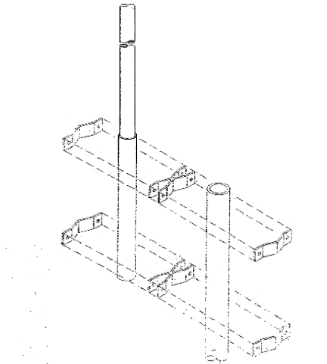
MOUNTING DIAGRAM
Rev. 1
NOTE: a) Clamps supplied will mount to a 1.75”-4” pipe.
Page 7
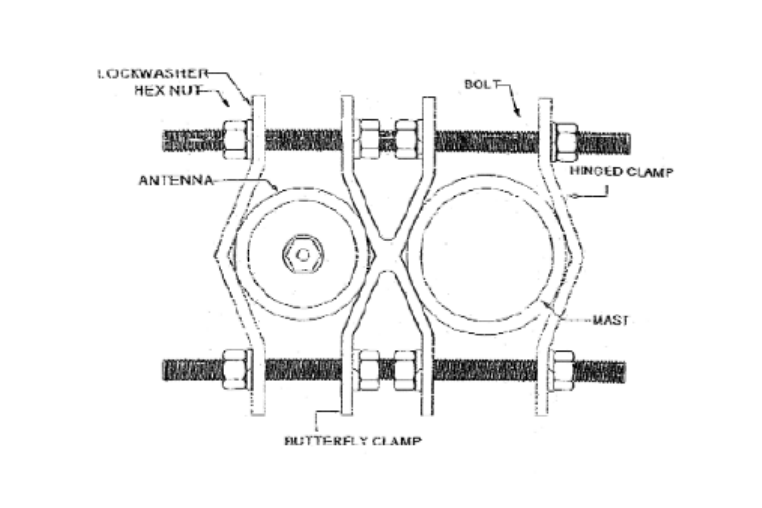
MOUNTING DIAGRAM (TOP VIEW)
NOTE: a.) Clamps supplied will mount to a 1.75” – 4” O.D. Pipe.
Page 8
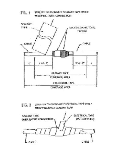
Most antenna problems are caused by coaxial cable connections that loosen due to
vibration, allowing moisture to penetrate the connector interface. We recommend that all
out door cable connections be weatherproofed using a procedure similar to the one
described below. To facilitate the task the sealant tape is supplied with each antenna
shipped, (the customer is responsible for providing the electrical tape).
Step 1.
Beginning as shown in Figure 1 by
overlapping half-width, wrap sealant
tape over entire connection.
Step 2.
Firmly press on the sealant tape.
Sealing it to the connection, itself and
the cable jackets, as shown in Figure2.
Page 9
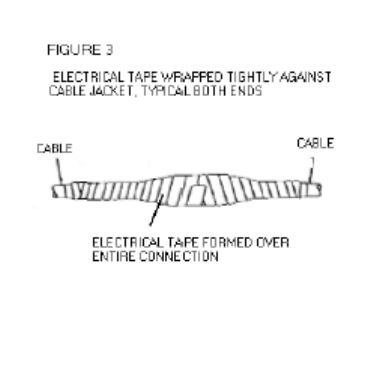
STEP 3.
While overlapping half-width, wrap
electrical tape (not supplied) over the
entire sealant tape connection. While
stretching tape, begin at one end of
formed sealant tape and work towards
on end approximately on inch beyond
end of sealant tape. Insure tight
electrical tape coverage over cable
jacket. Without breaking electrical tape,
reverse direction and wrap to other end,
again extending approximately one-inch
beyond end sealant tape. Again insure
tight coverage onto cable jacket.
Reverse direction again and wrap
electrical tape to center of connection
and cut.
Page 10