Ams 1073 Users Manual H
Neve 1084 Neve 1084
1073 to the manual 33b4bb60-5ed6-4318-a95c-f6f462aafcaf
2015-02-05
: Ams Ams-1073-Users-Manual-508815 ams-1073-users-manual-508815 ams pdf
Open the PDF directly: View PDF ![]() .
.
Page Count: 44
- Con tents
- 1073_84_user.pdf

© 2004 AMS Neve plc own the copyright of all
information and drawings contained in this manual which
are not to be copied or reproduced by any means or
disclosed in part or whole to any third party without
written permission.
As part of our policy of continual product improvement,
we reserve the right to alter specifications without notice
but with due regard to all current legislation.
Disclaimer: The information in this manual has been
carefully checked and is believed to be accurate at the
time of publication. However, no responsibility is taken by
us for inaccuracies, errors or omissions nor any liability
assumed for any loss or damage resulting either directly or
indirectly from use of the information contained within it.
AMS NEVE INC., NEW YORK
TEL: +1 (212) 965 1400 • FAX: +1 (212) 965 9306
AMS NEVE INC., HOLLYWOOD
TEL: +1 (818) 753 8789 • FAX: +1 (818) 623 4839
AMS NEVE PLC • BILLINGTON ROAD • BURNLEY
LANCS BB11 5UB • ENGLAND
TELEPHONE: +44 (0) 1282 457011 • FAX: +44 (0) 1282 417282
HEAD OFFICE
TELEPHONE: +44 (0) 20 7916 2828 • FAX: +44 (0) 20 7916 2827
LONDON OFFICE
NORTH AMERICAN OFFICES
e-mail: enquiry@ams-neve.com
http://www.ams-neve.com
AMS
NEVE
User Guide
527-341
Issue 3
1073 & 1084
Channel Amplifier

Con tents
In tro duc tion 1
High Pass Fil ter (re sis tor mod i fi ca tion) 1
Im por tant Note 1
In stal la tion 2
Di men sions 3
Power Re quire ments 3
Mains Sup ply (rack units) 4
DC Power Sup ply In di ca tors (rack units) 4
Phan tom Power 4
Out put Level Con trol 4
Con nec tor De tails 5
Am pli fier Con trols 6
1073 Mod ule 6
1084 Mod ule 7
Spec i fi ca tions 8
1073 and 1084 Mod ules 8
Re call Sheets 9
1073 - Ver ti cal Mod ule 9
1073 - Hor i zon tal Mod ule 10
1084 - Ver ti cal Mod ule 11
1084 - Hor i zon tal Mod ule 12
Ser vice In for ma tion 13
Sche matic Draw ing In dex - 1073/1084 Racks 13
Sche matic Draw ing In dex - 1073 Mod ule 13
Sche matic Draw ing In dex - 1084 Mod ule 14
User Guide Is sue 3 Page i
1073 & 1084 Chan nel Am pli fiers
In tro duc tion
These 45 series modules are the same as the original designs, and contain all of the original
components.
1073 Chan nel Am pli fiers
These very popular sounding mic pre's are considered by many to capture the very essence of the
Neve sound. In manufacture since the early 1970s, the Class A design offers 3 bands of EQ with
one fixed high frequency and a high pass filter.
1084 Chan nel Am pli fiers
Based on the same technology as the 1073s, the 1084s again deliver the unique sound and quality
of Neve. However, the 1084s offer additional features, including 3 switchable EQ bands with cut
and boost, a high Q for presence and low pass/high pass filters.
High Pass Fil ter (re sis tor mod i fi ca tion)
Im por tant Note
The high pass filter in both the 1073 & 1084 modules is a passive design and as such must be
correctly terminated to achieve a maximally flat response.
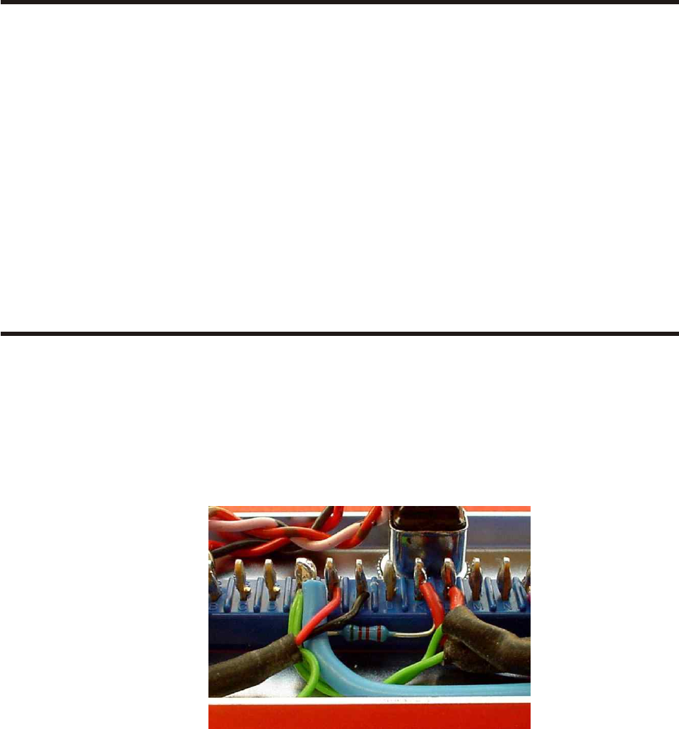
In order to achieve this there is a 5k1 resistor fitted inside the module on the back connector
between pin E (0v) and pin K (fader send) see diagram below:
In situations where the fader connection is not used (most Neve 45 series consoles except
BCM10's) then the resistor remains in place.
In situations where the fader connection is used (BCM10's and AMS Neve 1073/1084 racks)
then the 5k1 resistor should be disconnected and replaced with a fader or potentiometer whose
value is 4k7 / 5k ohms.
-All mod ules which leave the fac tory with ei ther a 3U or 5U rack unit will have the 5K1 re sis tor
re moved.
Failure to do so will result in incorrect levels and uneven frequency response.
User Guide Is sue 3 Page 1
1073 & 1084 Chan nel Am pli fiers In tro duc tion
In stal la tion
The 1073s and 1084s are available as stand-alone modules, or in a choice of two housings.
The 3U rack houses two modules mounted horizontally in a 19” rack-mounting unit.
The 5U rack houses eight modules mounted vertically in a 19” rack-mounting unit.
Both have rear panels with XLRs for transformer balanced I/O.
The 3U rack rear panel has a fused, voltage selector IEC mains input connector. The 5U rack has a
free standing AC supply with a fused, voltage selector IEC mains input connector and connects to
the rack via a connector and a 1.5 meter cable.
Modules of any combination can be fitted into a rack unit.
User Guide Is sue 3 Page 2
1073 & 1084 Chan nel Am pli fiers In stal la tion
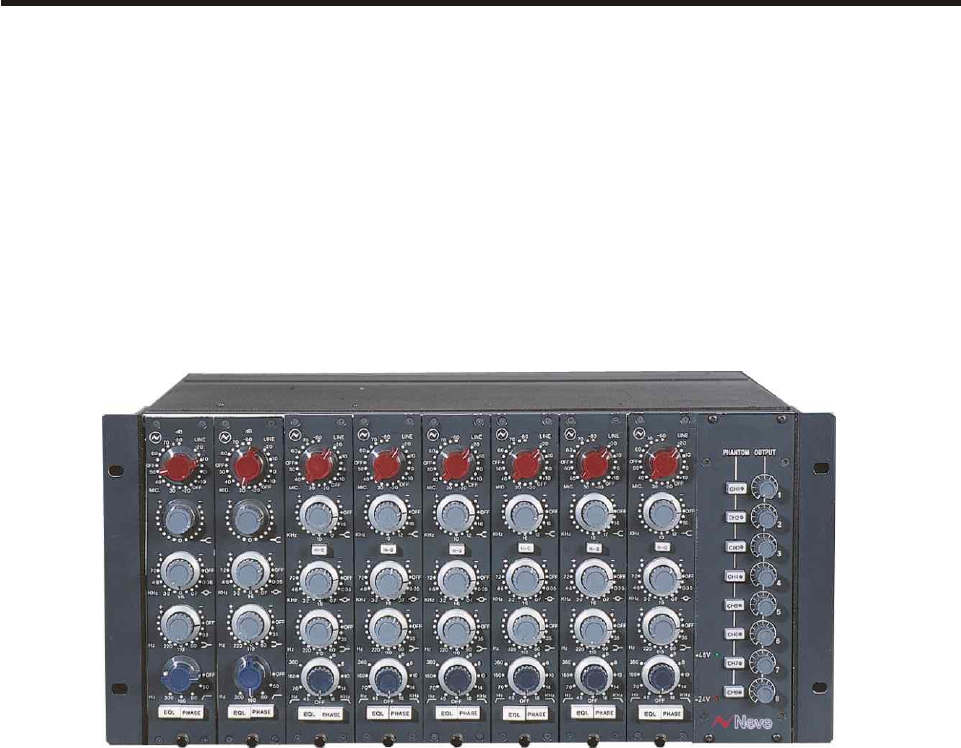
Ex am ple: 5U Rack fit ted with two 1073 mod ules and six 1084 mod ules
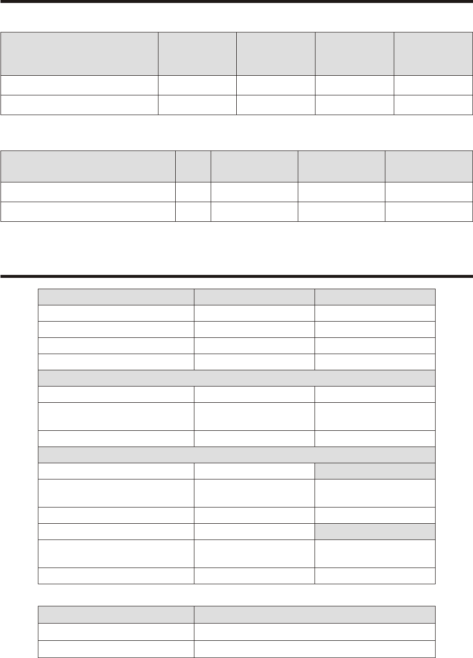
Di men sions
Stand-alone Mod ules Width
mm (inches)
Height
mm (inches)
Depth
mm (inches)
Ap prox.
Weight
kg (lbs)
1073 Module 45 (1.8) 222 (8.75) 254 (10) 2.5 (5.5)
1084 Module 45 (1.8) 222 (8.75) 254 (10) 2.5 (5.5)
19" Rack Mount ing U Depth
mm (inches)
Height
mm (inches)
Ap prox. Weight
kg (lbs)
2 Mod ule Ver sion 3405 (16) 133 (5.25) 11 (24.2) *
8 Mod ule Ver sion 5405 (16) 222 (8.75) 30 (66) *
* Fully populated rack
Power Re quire ments
Rack Units 3U 5U
Rated Volt age 100- 230V AC 100- 230V AC
Rated Fre quency 50- 60 Hz 50- 60Hz
Rated Cur rent 0.5A Max 0.8A Max
Pri mary Pro tec tion Fuse:
Op er at ing Volt age 100- 230V AC 100- 230V AC
Fuse Rat ing and Type T0.5A H 250V
20mm x 5mm CE RAMIC
T1A H 250V
20mm x 5mm CE RAMIC
Lo ca tion IEC Mains con nec tor IEC Mains con nec tor
Sec on dary Pro tec tion Fuse:
Out put Volt age 24V DC
Fuse Rat ing and Type T 2.0A L 250V
20mm x 5mm GLASS
Lo ca tion F1
Out put Volt age 48V DC
Fuse Rat ing and Type T 250mA L 250V
20mm x 5mm GLASS
Lo ca tion F2
Modules Power
1073 Mod ule 106mA ±10mA at 24V DC. Neg a tive Earth
1084 Mod ule 106mA ±10mA at 24V DC. Neg a tive Earth
User Guide Is sue 3 Page 3
1073 & 1084 Chan nel Am pli fiers Di men sions

Mains Sup ply (rack units)
The 3U rack has a fused, voltage selector IEC mains input connector.
The 5U rack has a free standing AC supply with a fused, voltage selector IEC mains input connector
and connects to the rack via a connector and a 1.5 meter cable.
The mains switch on the rear panel of the 3U rack unit is non-illuminating.
The CH (chassis) and 0V are linked internally.
DC Power Sup ply In di ca tors (rack units)
The red LED on the front panel of both 3U and 5U rack units indicates +24V power healthy when
illuminated.
The green LED on the front panel of both 3U and 5U rack units indicates +48V power healthy when
illuminated.
Phan tom Power
Phantom power can be supplied to each module by pressing the phantom power switch on the front
panel of the 3U or 5U rack. The LED in the switch will illuminate confirming that phantom power is
supplied.
Out put Level Con trol
Each channel has an independent Output Level Control. The control is post-input, post-EQ and
pre-output. This control can reduce the level at the output.
When the Output Control is fully clockwise the output gain is unity. The output is 20dB down with
the control in the mid-position.
User Guide Is sue 3 Page 4
1073 & 1084 Chan nel Am pli fiers Phan tom Power
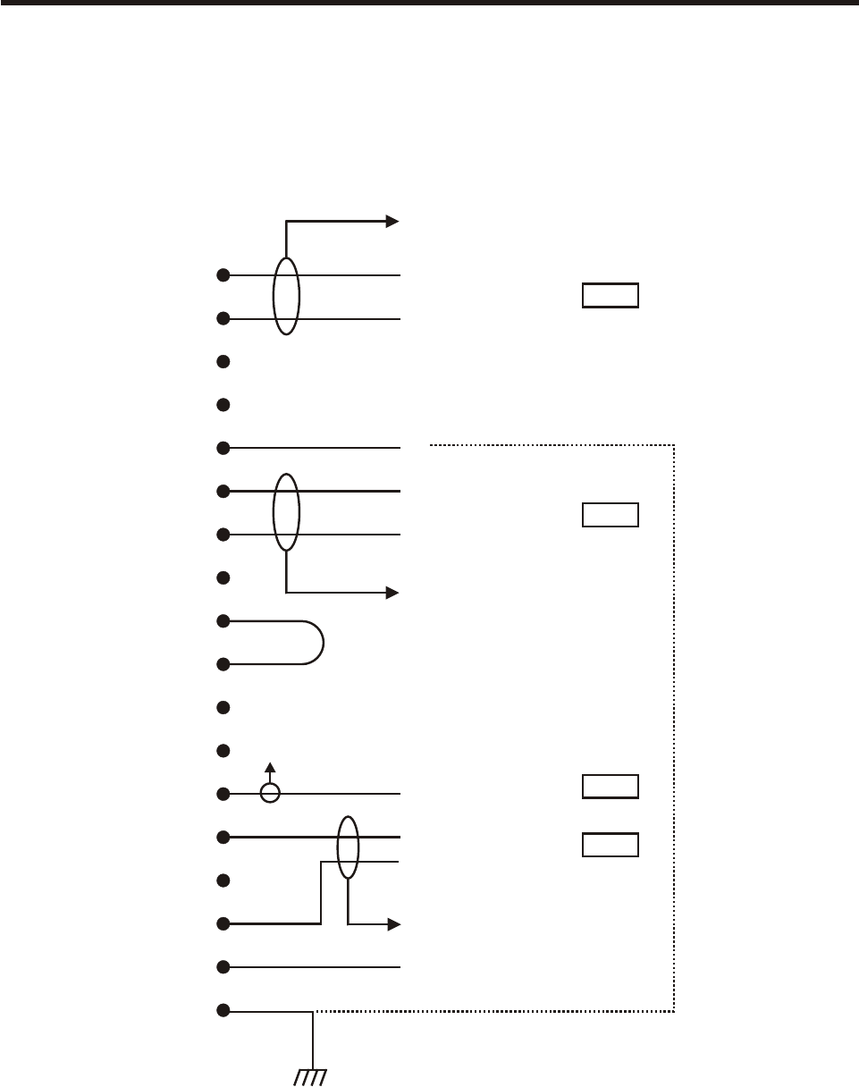
Con nec tor De tails
User Guide Is sue 3 Page 5
1073 & 1084 Chan nel Am pli fiers Con nec tor De tails
Standalone 1073 & 1084
Module Wiring to 18 way Free Plug
A
B
C
D
E
F
H
J
K
L
M
N
P
R
S
T
U
V
0V
Hi
Lo
0V
Hi
Lo
Link
Unbalanced O/P
Hi
Lo
BAL O/P
+24V at 106mA
Mic I/P
Line I/P
-20dBu
-3dBu
0dBu
0dBu
Technical
Earth Link
To Pin V
To Pin V
To Pin V
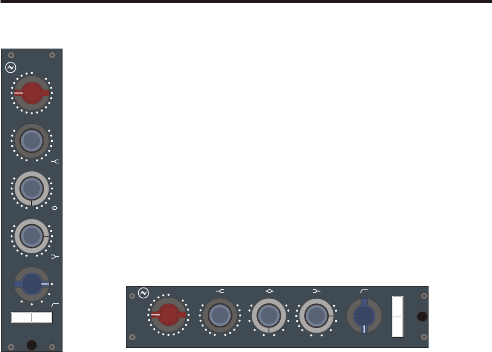
Am pli fier Con trols
1073 Mod ule
High Frequency: Smooth +/-16dB fixed frequency shelving at 12kHz.
Low Frequency: Smooth +/-16dB shelving with selectable frequencies of 35Hz,
60Hz, 110Hz & 220Hz.
Mid Frequency: Smooth +/-18dB peaking, fixed 'Q' with, selectable centre
frequencies of 0.36kHz, 0.7kHz, 1.6kHz, 3.2kHz, 4.8kHz &
7.2kHz.
High Pass Filter: 18dB per octave slope, switchable between 50Hz, 80Hz,
160Hz & 300Hz.
EQL Button: Switches the equaliser in or out of circuit.
Phase Button: Gives 180° Phase change at Balanced Output.
User Guide Is sue 3 Page 6
1073 & 1084 Chan nel Am pli fiers Am pli fier Con trols
dB
LINE
-20
10
0
+10
OFF
-2030
MIC
40
50
OFF
60
70 -80
+-
0
+-
0
OFF
0.36
0.7
1.6
3.2
KHz
Hz
4.8
7.2
+-
0
OFF
35
60
110
220
Hz
OFF
50
80
160
300
EQL PHASE
dB
LINE
-20
10
0
+10
OFF
-2030
MIC
40
50
OFF
60
70 -80
+-
0
+-
0
OFF
0.36
0.7
1.6
3.2
KHz
4.8
7.2
Hz
+-
0
OFF
35
60
110
220
OFF
50
80
160
300
Hz
E
Q
L
P
H
A
S
E
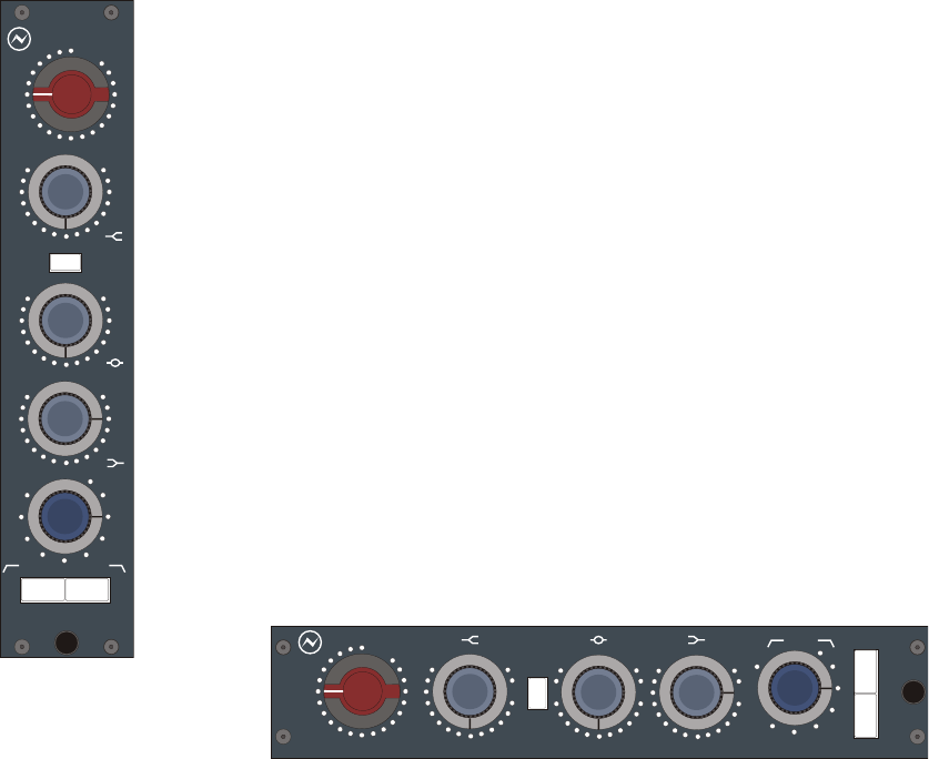
1084 Mod ule
High Frequency: Smooth +/-16dB shelving wit selectable frequencies of 10kHz,
12kHz and 16kHz.
Low Frequency: Smooth +/-16dB shelving with selectable frequencies of 35Hz,
60Hz, 110Hz & 220Hz.
Mid Frequency: Smooth +/-12dB or +/-18dB peaking with switchable 'High Q',
selectable centre frequencies of 0.36kHz, 0.7kHz, 1.6kHz,
3.2kHz, 4.8kHz & 7.2kHz.
High Pass Filter: 18dB per octave slope, switchable between 45Hz, 70Hz, 160Hz
& 360Hz.
Low Pass Filter: 18dB per octave slope, switchable between 6kHz, 8kHz, 10kHz,
14kHz, & 18kHz.
EQL Button: Switches the equaliser in or out of circuit.
Phase Button: Gives 180° Phase change at Balanced Output.
User Guide Is sue 3 Page 7
1073 & 1084 Chan nel Am pli fiers Am pli fier Con trols
dB
LINE
-20
10
0
+10
OFF
-2030
MIC
40
50
OFF
60
70 -80
+-
OFF
16
12
10
KHz
+-
OFF
0.35
0.7
1.6
3.2
KHz
4.8
7.2
Hz
+-
OFF
35
60
110
220
Hz
10
14
18
OFF
45
160
70
8
6
360
KHz
EQL PHASE
Hi-Q
dB
LINE
-20
10
0
+10
OFF
-2030
MIC
40
50
OFF
60
70 -80
+-
OFF
16
12
10
KHz
E
Q
L
P
H
A
S
E
+
OFF
0.35
0.7
1.6
3.2
4.8
7.2
Hz
+-
OFF
35
60
110
220
Hz
10
14
18
OFF
45
1
6
0
70
8
6
360
KHz
Hi
Q
KHz
-

Spec i fi ca tions
1073 and 1084 Mod ules
Microphone Input: Input Impedance 300W or 1200W, gain +80db to +20dB in
5dB steps.
Line Input: Input Impedance 10,000W bridging, gain +20dB to -10dB in
5dB steps.
Both inputs are transformer balanced and earth free.
Output: Maximum output is >+26dBu into 600W. Output impedance is
75W @1kHz.
Output is transfomer balanced and earth free.
Distortion: Not more than 0.07% from 50Hz to 10kHz at +20dBu output
(80kHz bandwidth) into 600W.
Frequency Response: +/-0.5dB 20Hz to 20kHz, -3dB at 40kHz Eq Out.
Noise: Not more than -83dBu at all Line gain settings Eq In/Out
(22Hz to 22kHz bandwidth).
EIN better than -125dBu @ 60dB gain.
User Guide Is sue 3 Page 8
1073 & 1084 Chan nel Am pli fiers Spec i fi ca tions
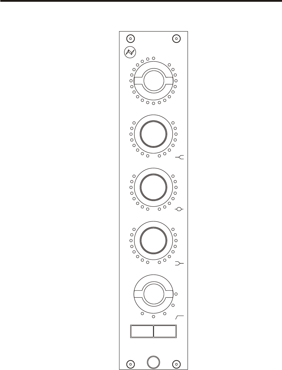
Re call Sheets
1073 - Vertical Mod ule
User Guide Is sue 3 Page 9
1073 & 1084 Chan nel Am pli fiers Re call Sheets
dB
LINE
-20
10
0
+10
OFF
-2030
MIC
40
50
OFF
60
70 -80
+-
0
+-
0
OFF
0.36
0.7
1.6
3.2
KHz
Hz
4.8
7.2
+-
0
OFF
35
60
110
220
Hz
OFF
50
80
160
300
EQL PHASE
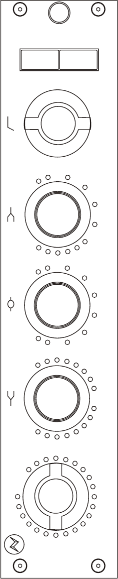
1073 - Hor i zon tal Mod ule
User Guide Is sue 3 Page 10
1073 & 1084 Chan nel Am pli fiers Re call Sheets
dB
LINE
-20
10
0
+10
OFF
-2030
MIC
40
50
OFF
60
70 -80
+-
0
+-
0
OFF
0.36
0.7
1.6
3.2
KHz
4.8
7.2
Hz
+-
0
OFF
35
60
110
220
OFF
50
80
160
300
Hz
E
Q
L
P
H
A
S
E
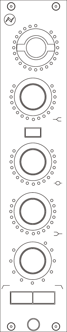
1084 - Ver ti cal Mod ule
User Guide Is sue 3 Page 11
1073 & 1084 Chan nel Am pli fiers Re call Sheets
dB
LINE
-20
10
0
+10
OFF
-2030
MIC
40
50
OFF
60
70 -80
+-
OFF
16
12
10
KHz
+-
OFF
0.35
0.7
1.6
3.2
KHz
4.8
7.2
Hz
+-
OFF
35
60
110
220
Hz
10
14
18
OFF
45
160
70
8
6
360
KHz
EQL PHASE
Hi-Q
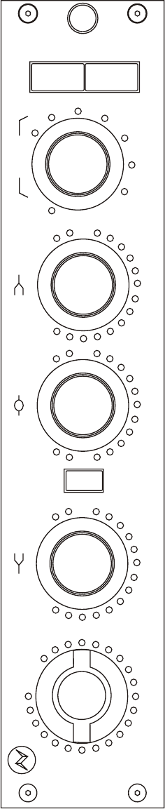
1084 - Hor i zon tal Mod ule
User Guide Is sue 3 Page 12
1073 & 1084 Chan nel Am pli fiers Re call Sheets
dB
LINE
-20
10
0
+10
OFF
-2030
MIC
40
50
OFF
60
70 -80
+-
OFF
16
12
10
KHz
E
Q
L
P
H
A
S
E
+
OFF
0.35
0.7
1.6
3.2
4.8
7.2
Hz
+-
OFF
35
60
110
220
Hz
10
14
18
OFF
45
1
6
0
70
8
6
360
KHz
Hi
Q
KHz
-

Ser vice In for ma tion
Sche matic Draw ing In dex - 1073/1084 Racks
3U Horizontal Rack (AM5028) AM5028 Assembly Drawing
AM5028 Wiring Diagram
5U Vertical Rack (AM5033) UNDER DEVELOPMENT
Sche matic Draw ing In dex - 1073 Mod ule
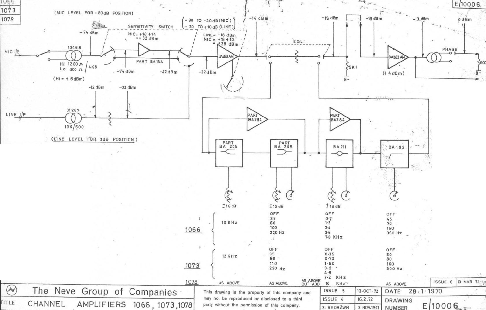
1073 Channel Amplifier (PL31073-C) E10006 Block Diagram
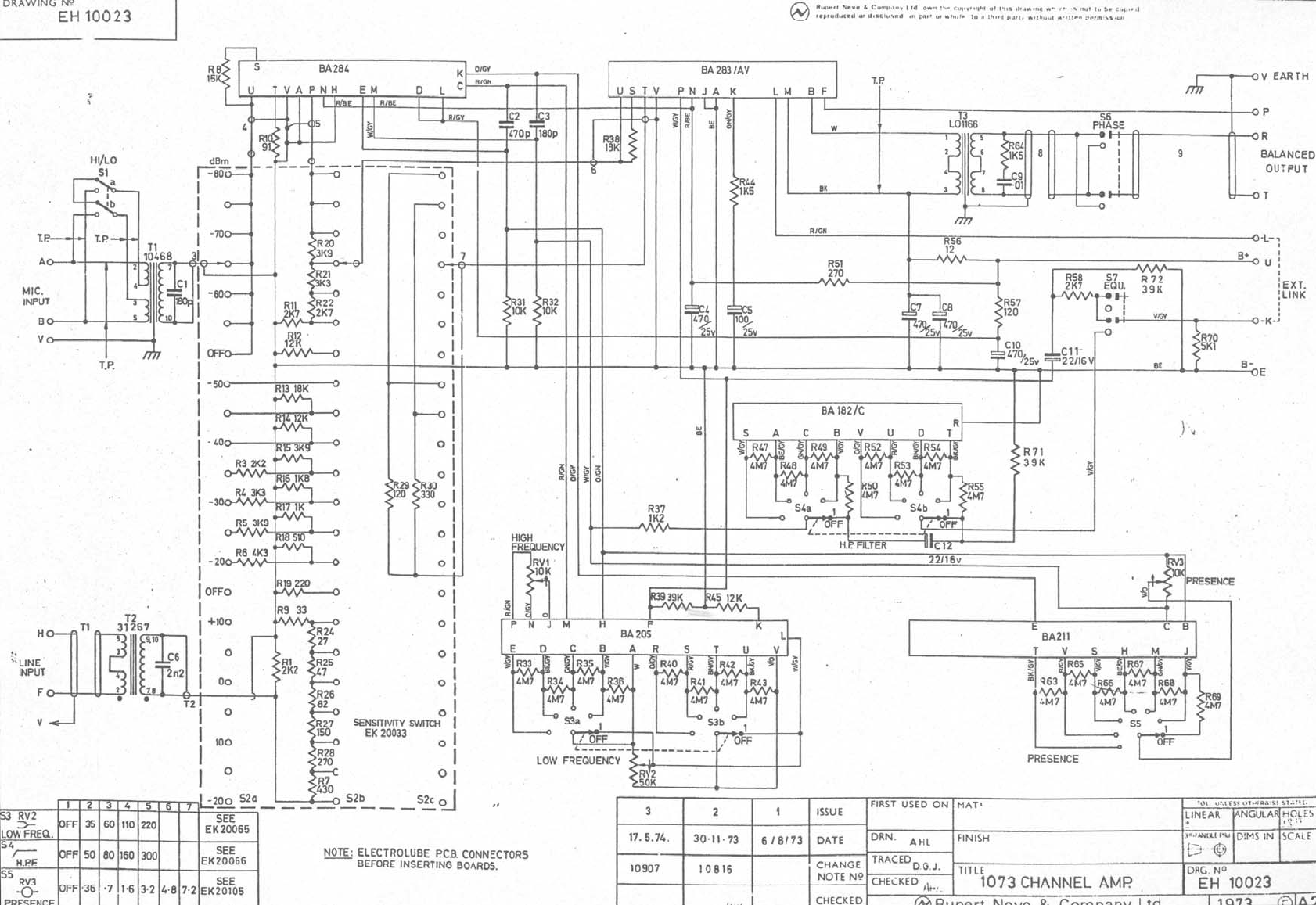
EH10023 Circuit Diagram
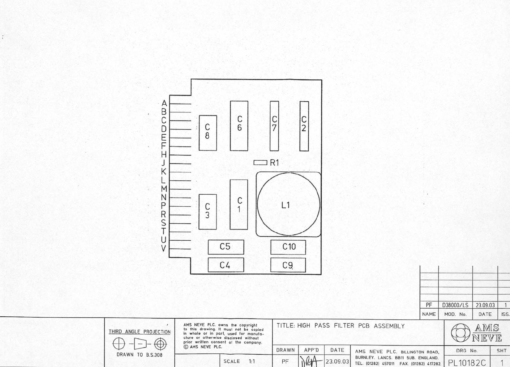
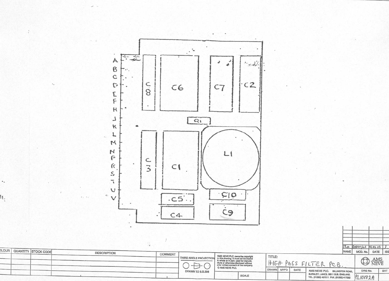
High Pass Filter (PL10182/C) PL10182/C Assembly Drawing
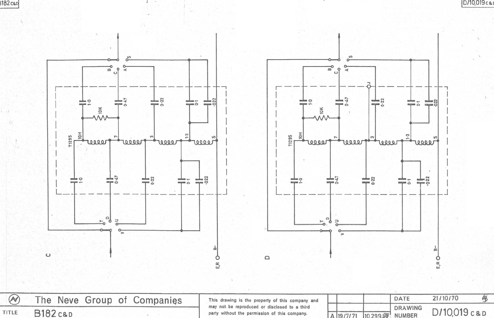
D/10019C Circuit Diagram
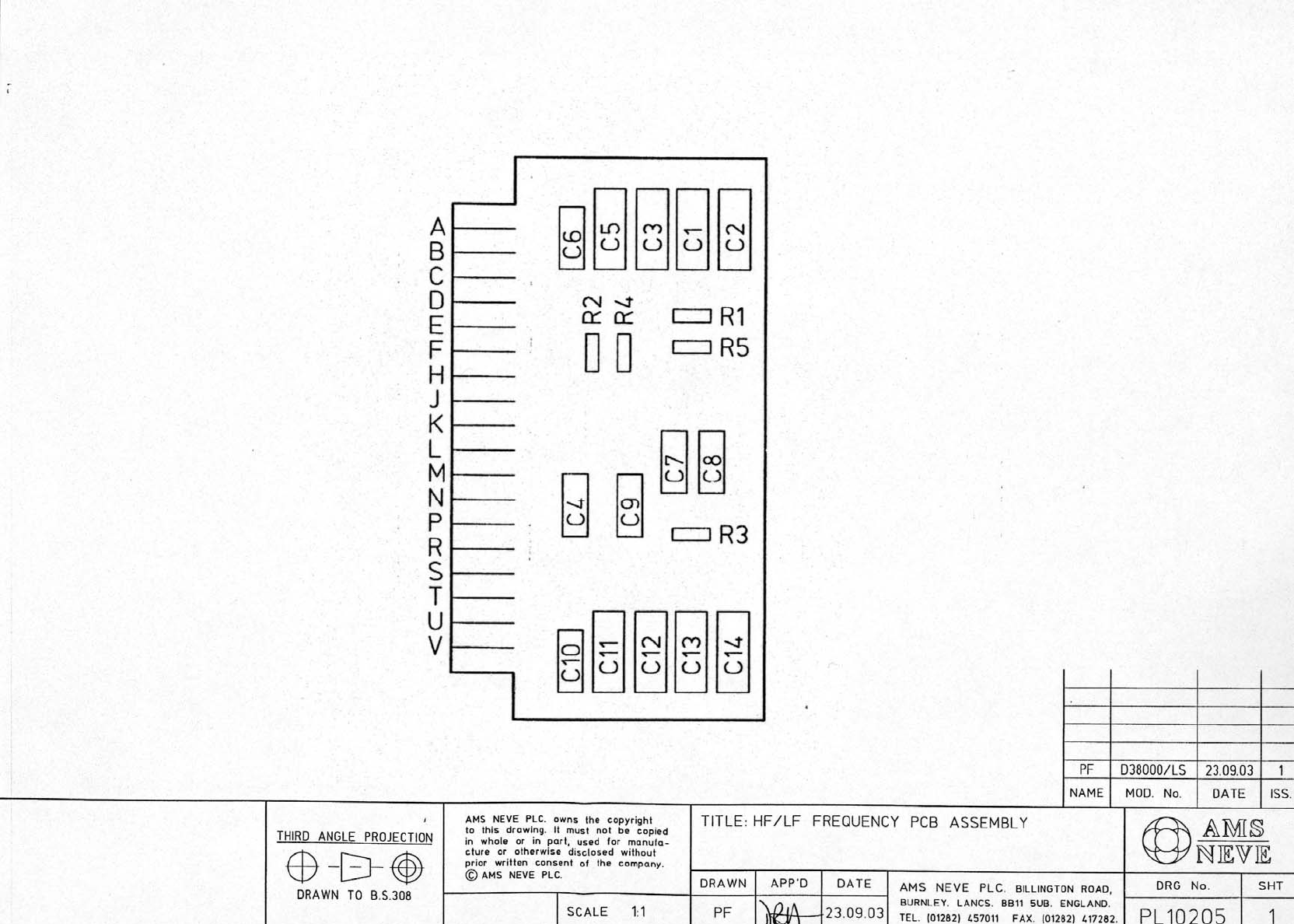
HF/LF EQ Frequency (PL10205) PL10205 Assembly Drawing
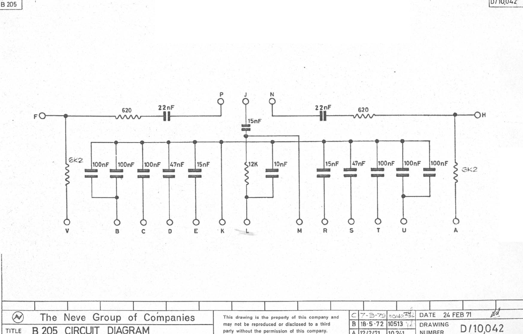
D/10042 Circuit Diagram
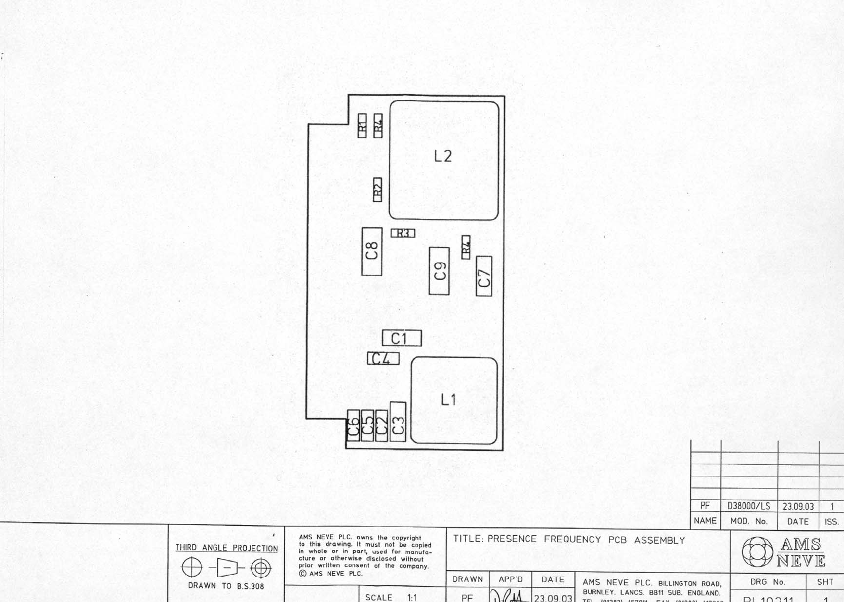
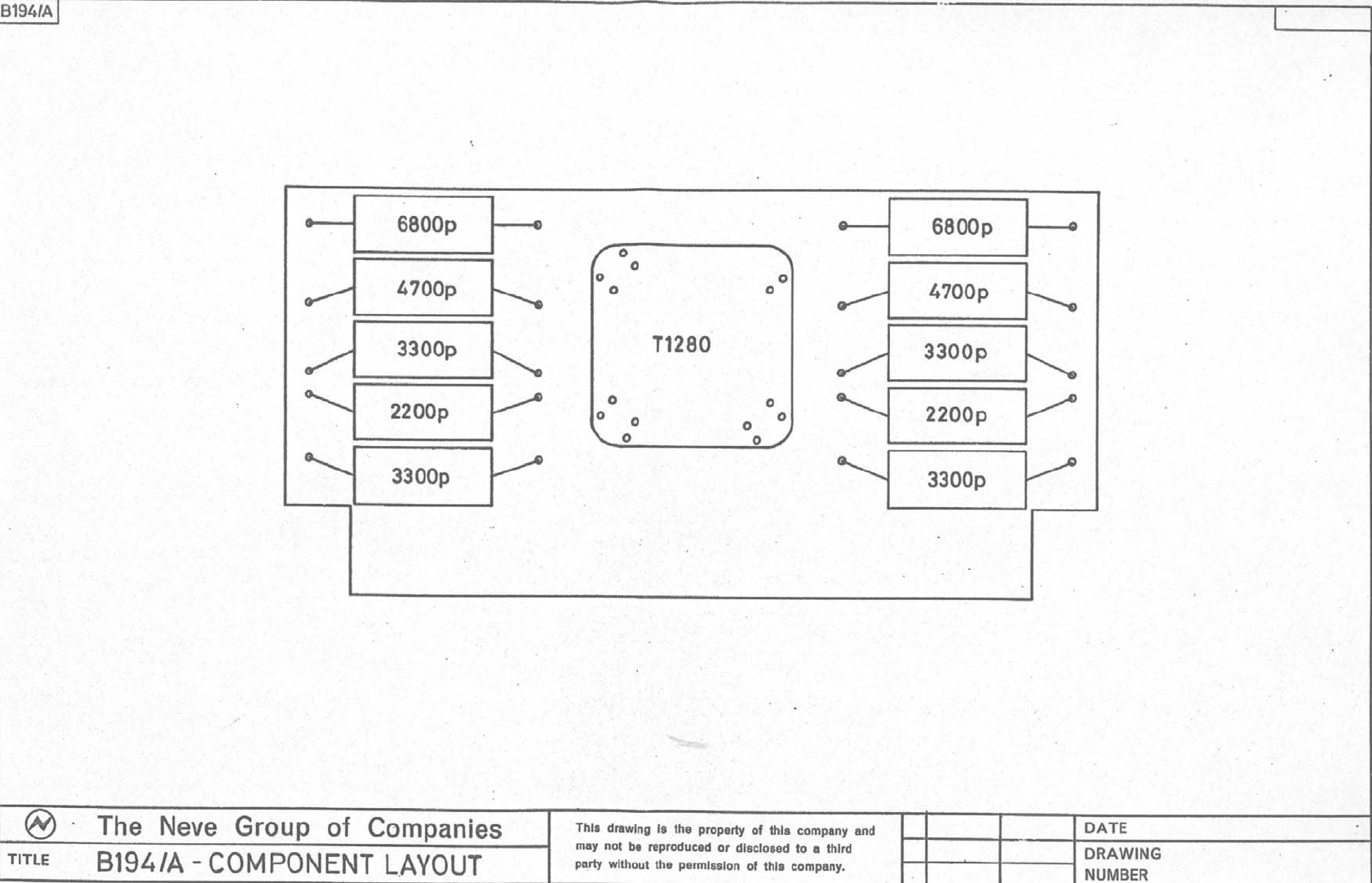
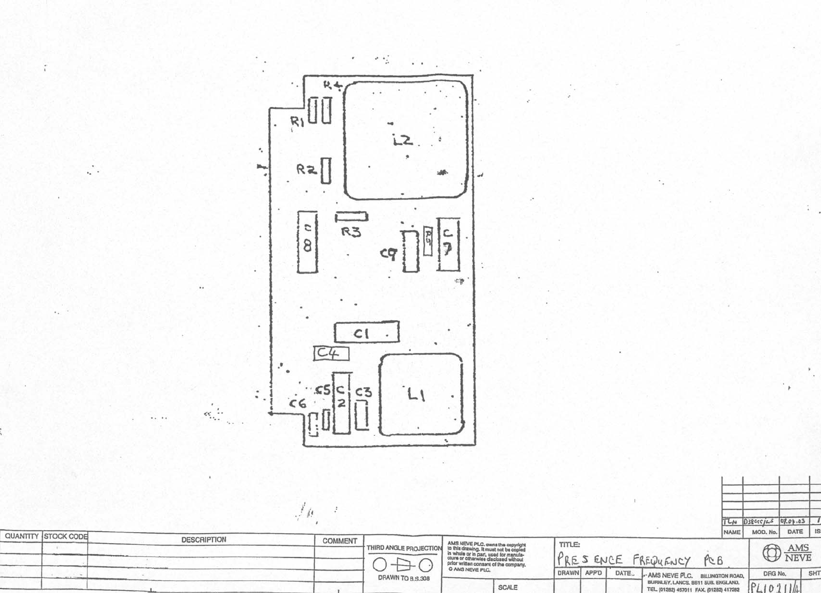
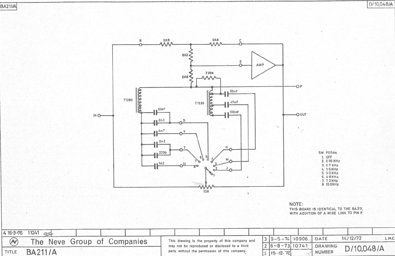
Presence Frequency (PL10211) BA211 Assembly Drawing
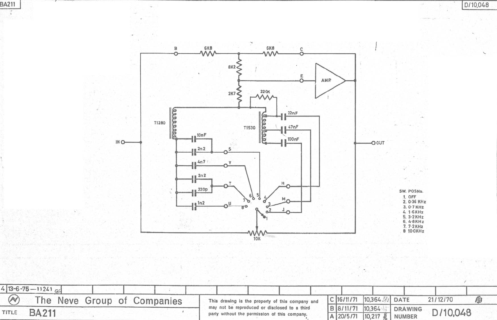
D/10048 Circuit Diagram
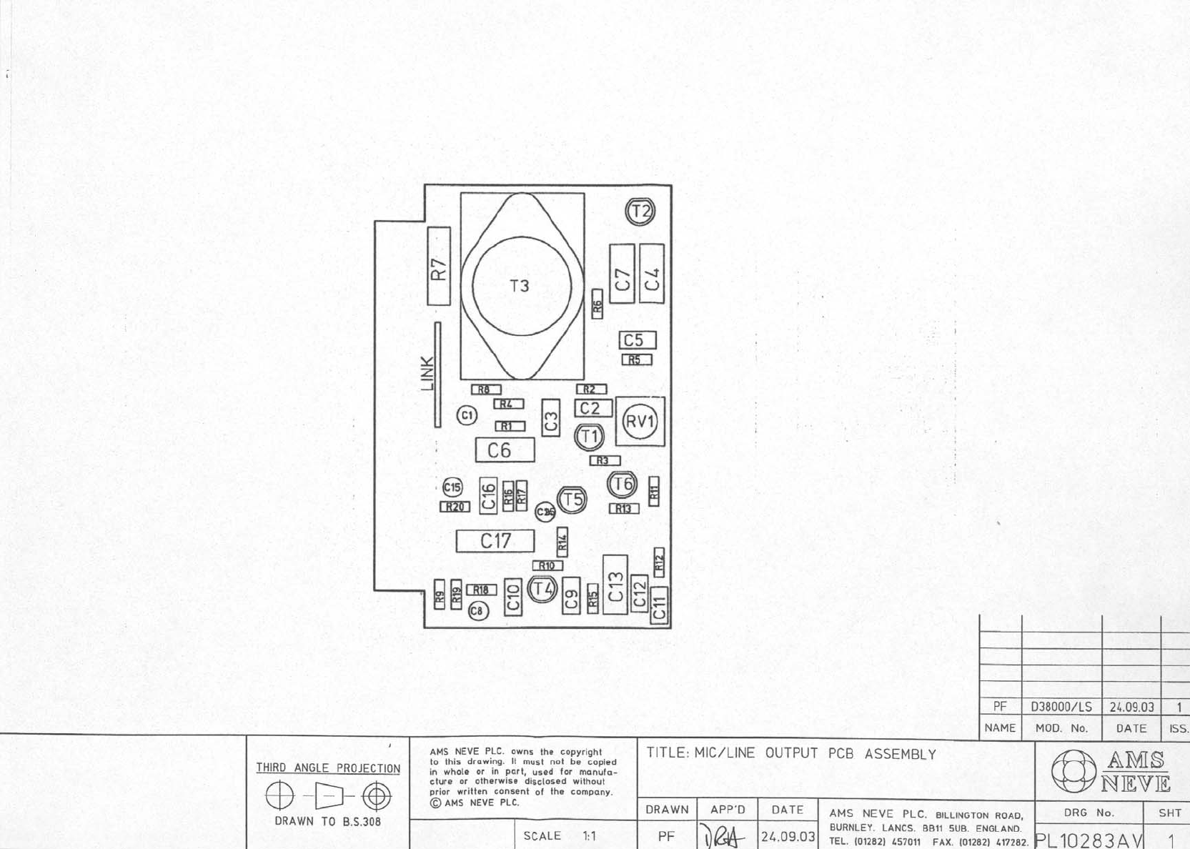
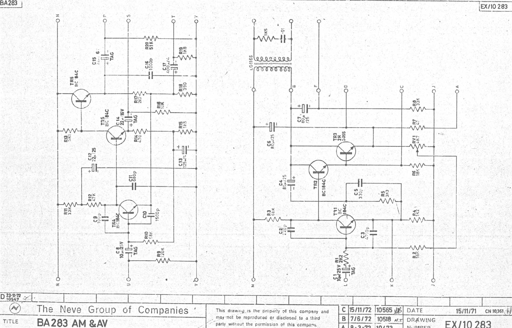
Mic Line Output (PL10283AV) PL10283 Assembly Drawing
EX10283 Circuit Diagram
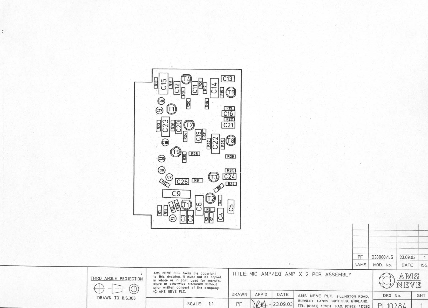
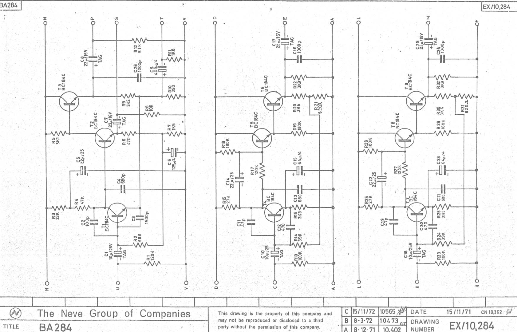
Mic Amp/EQ Amp (PL10284) PL10284 Assembly Drawing
EX10284 Circuit Diagram
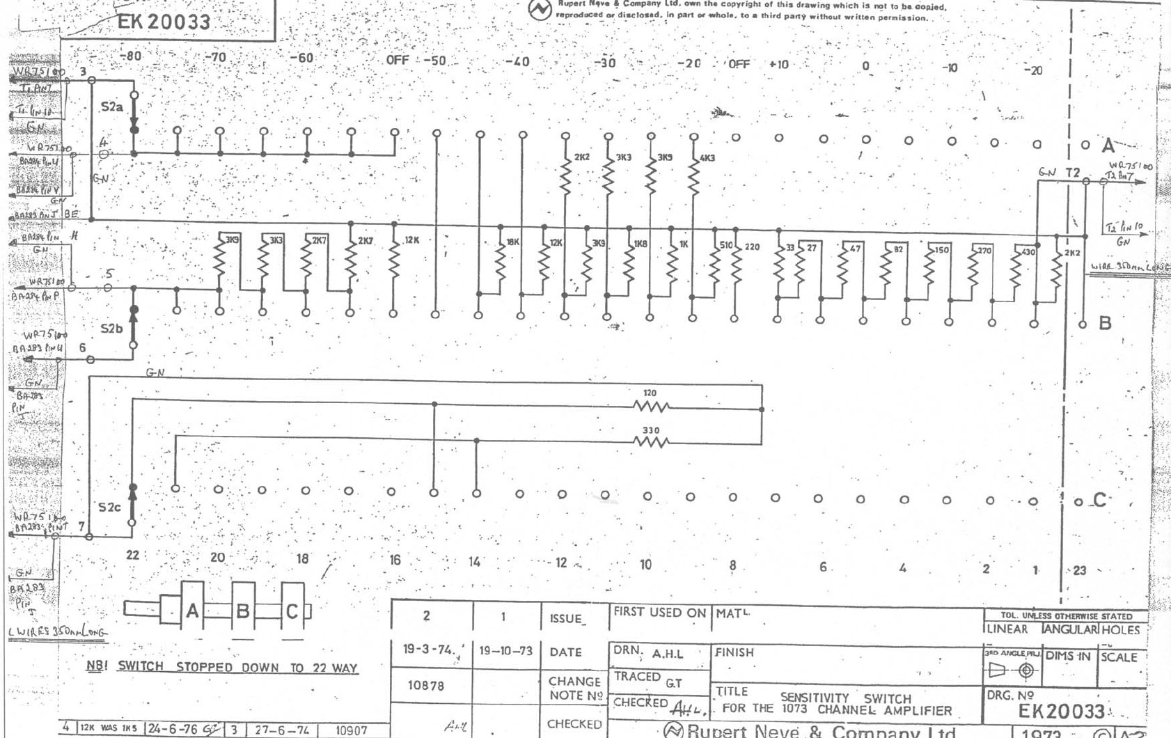
Sensitivity Switch (PL20033) EK20033 Wiring Diagram
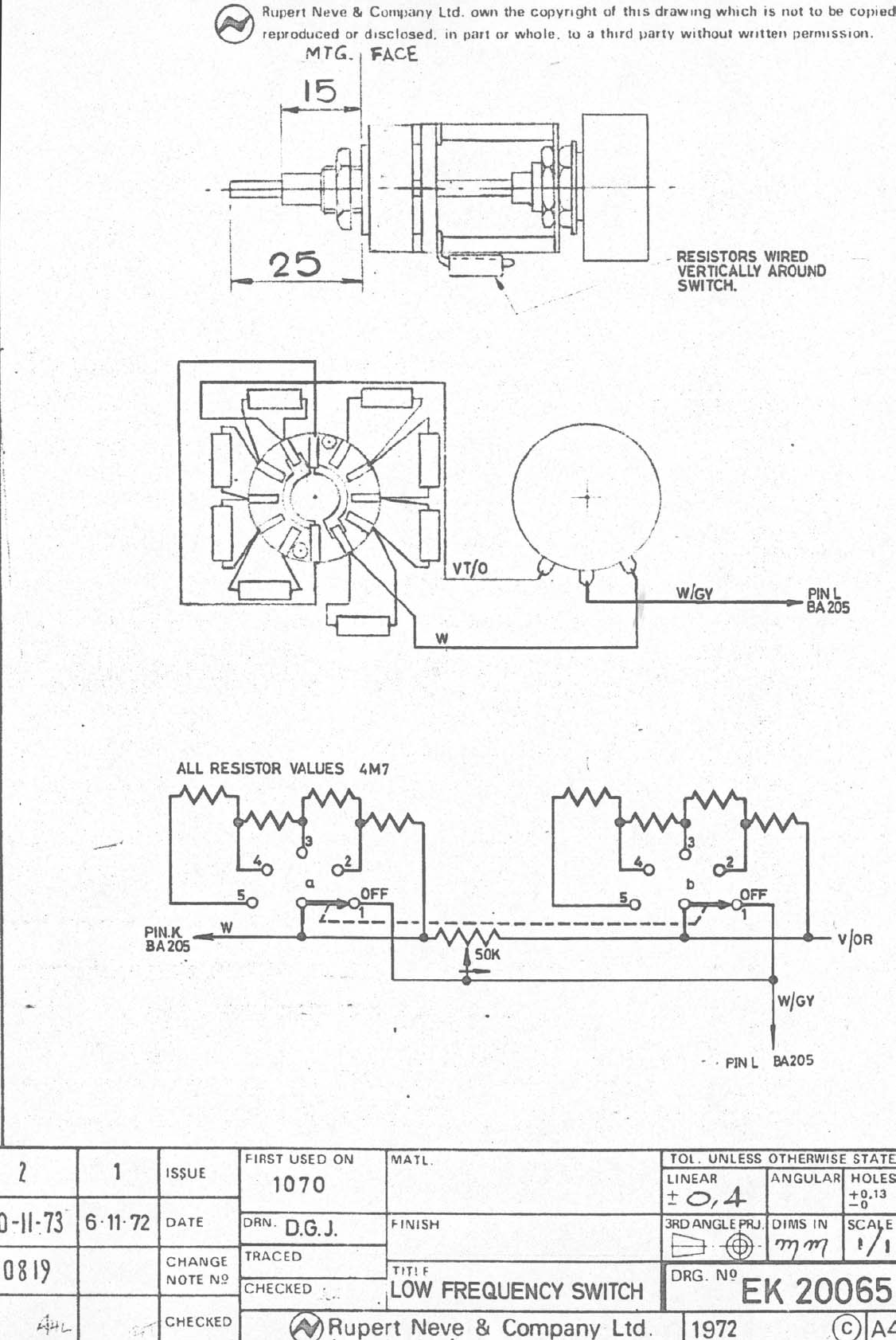
Low Frequency Switch (PL20065) EK20065 Wiring Diagram
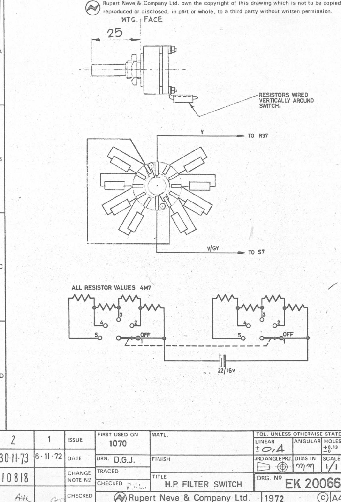
HP Filter Switch (PL20066) EK20066 Wiring Diagram
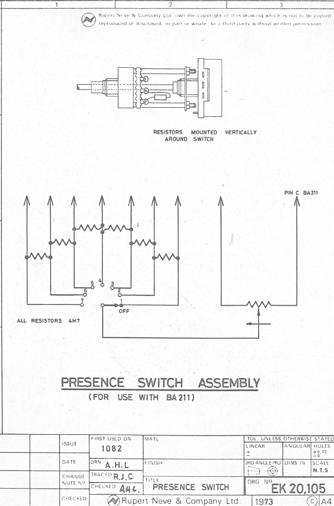
Presence Switch (PL20105) EK20105 Wiring Diagram
User Guide Is sue 3 Page 13
1073 & 1084 Chan nel Am pli fiers Ser vice In for ma tion
Sche matic Draw ing In dex - 1084 Mod ule
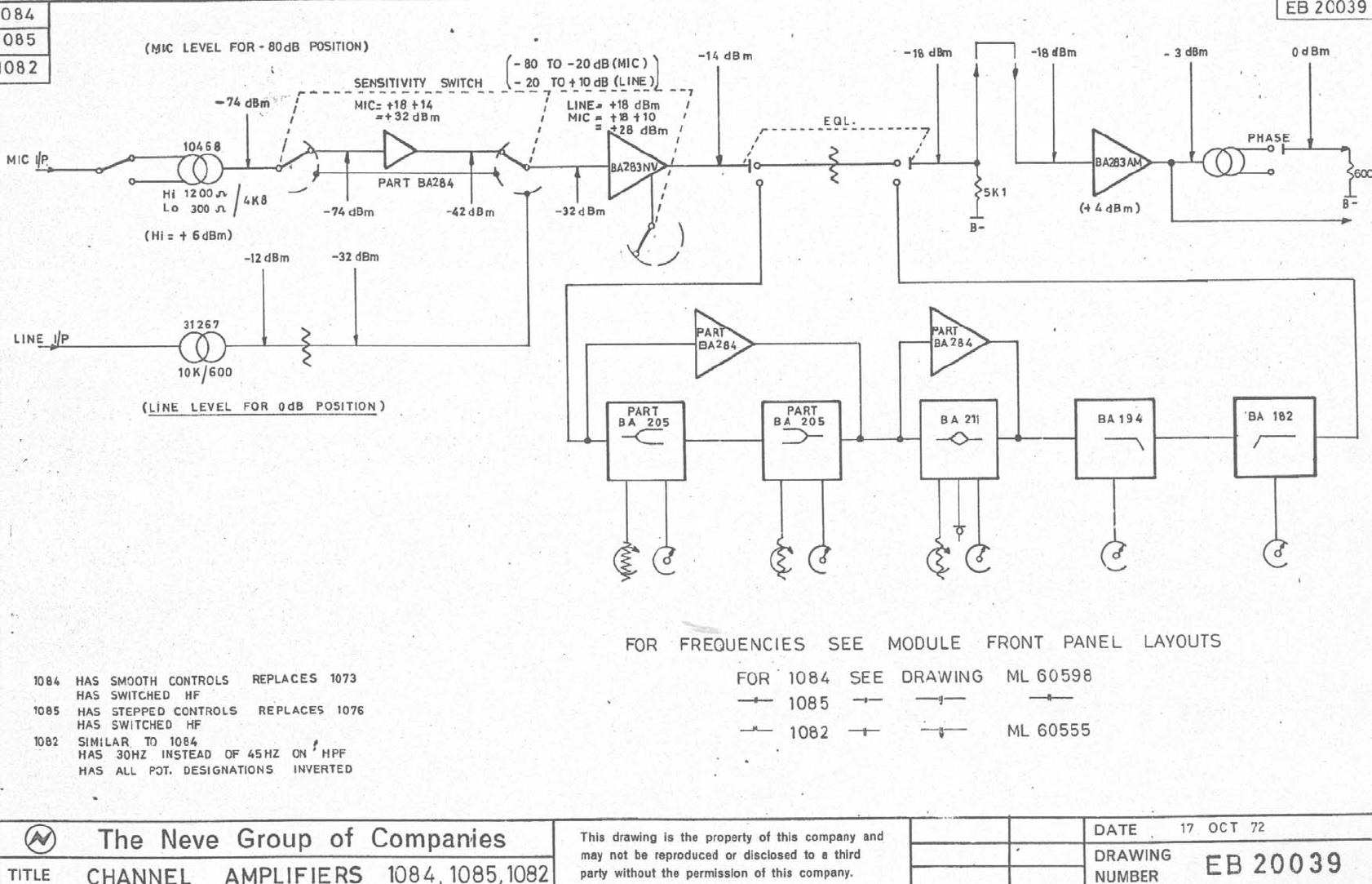
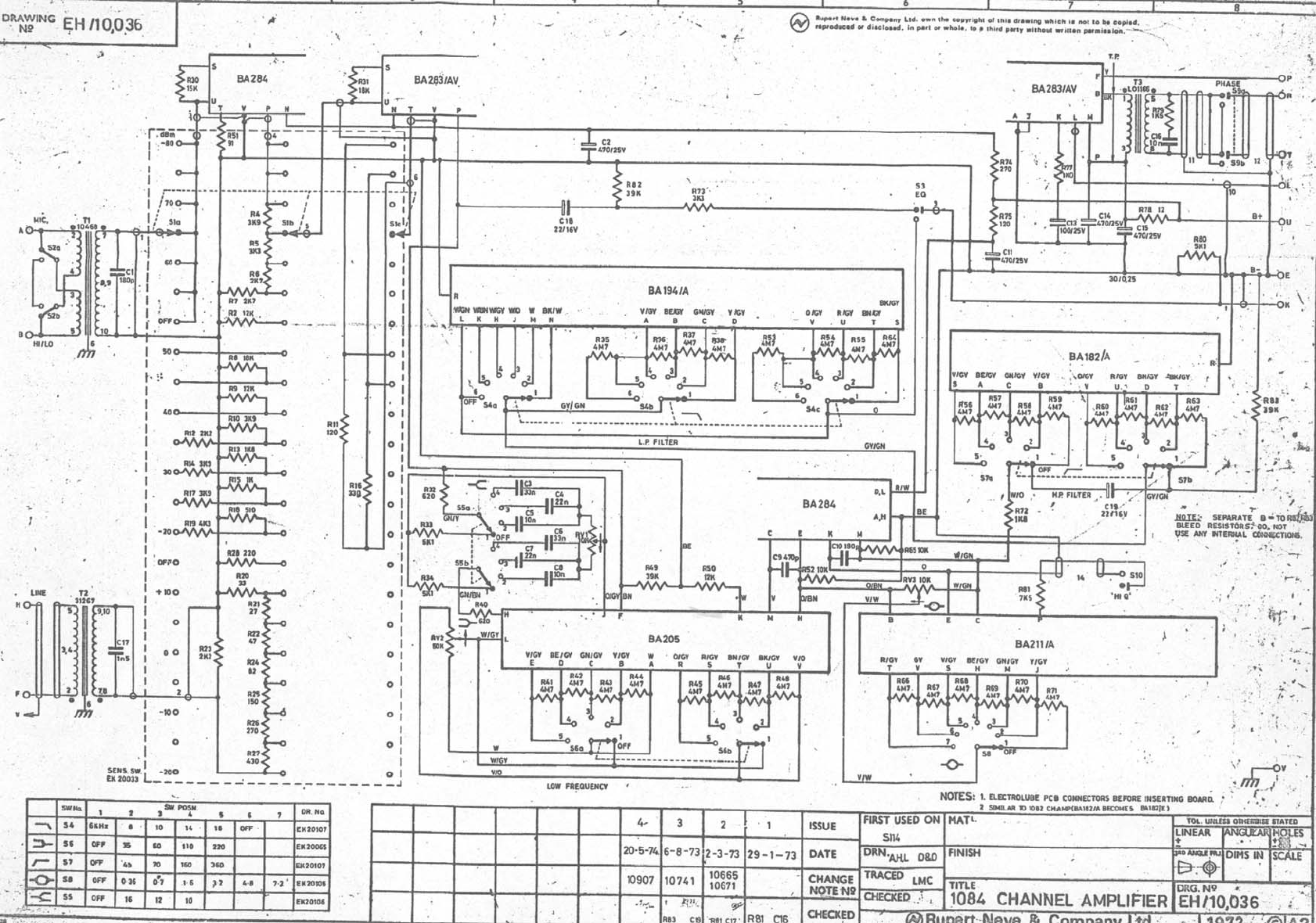
1084 Channel Amplifier (PL31084-C) EB20039 Block Diagram
EH10036 Circuit Diagram
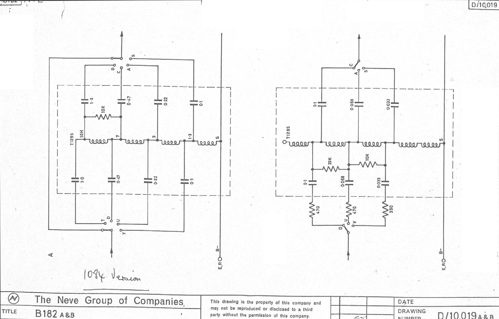
High Pass Filter (PL10182/A) PL10182/A Assembly Drawing
D/10019A Circuit Diagram
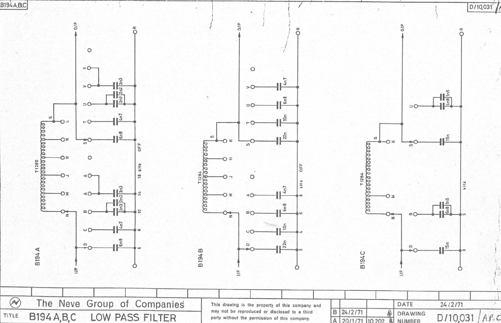
Low Pass Filter (PL10194/A) PL10194/A Assembly Drawing
D10031/A Circuit Diagram
HF/LF EQ Frequency (PL10205) See 1073 drawing section
Presence Frequency (PL10211/A) PL10211/A Assembly Drawing
D/10048/A Circuit Diagram
Mic Line Output (PL10283AV) See 1073 drawing section
Mic Amp/EQ Amp (PL10284) See 1073 drawing section
Sensitivity Switch (PL20033) See 1073 drawing section
Low Frequency Switch (PL20065) See 1073 drawing section
Presence Switch (PL20105) See 1073 drawing section
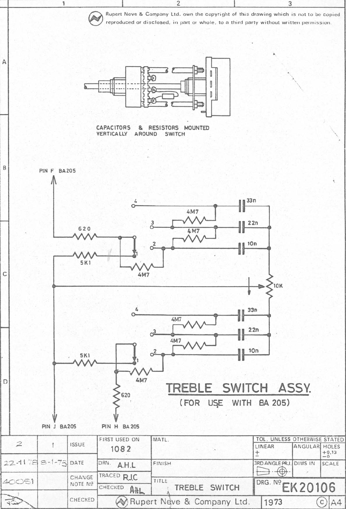
High Frequency Switch (PL20106) EK20106 Wiring Diagram
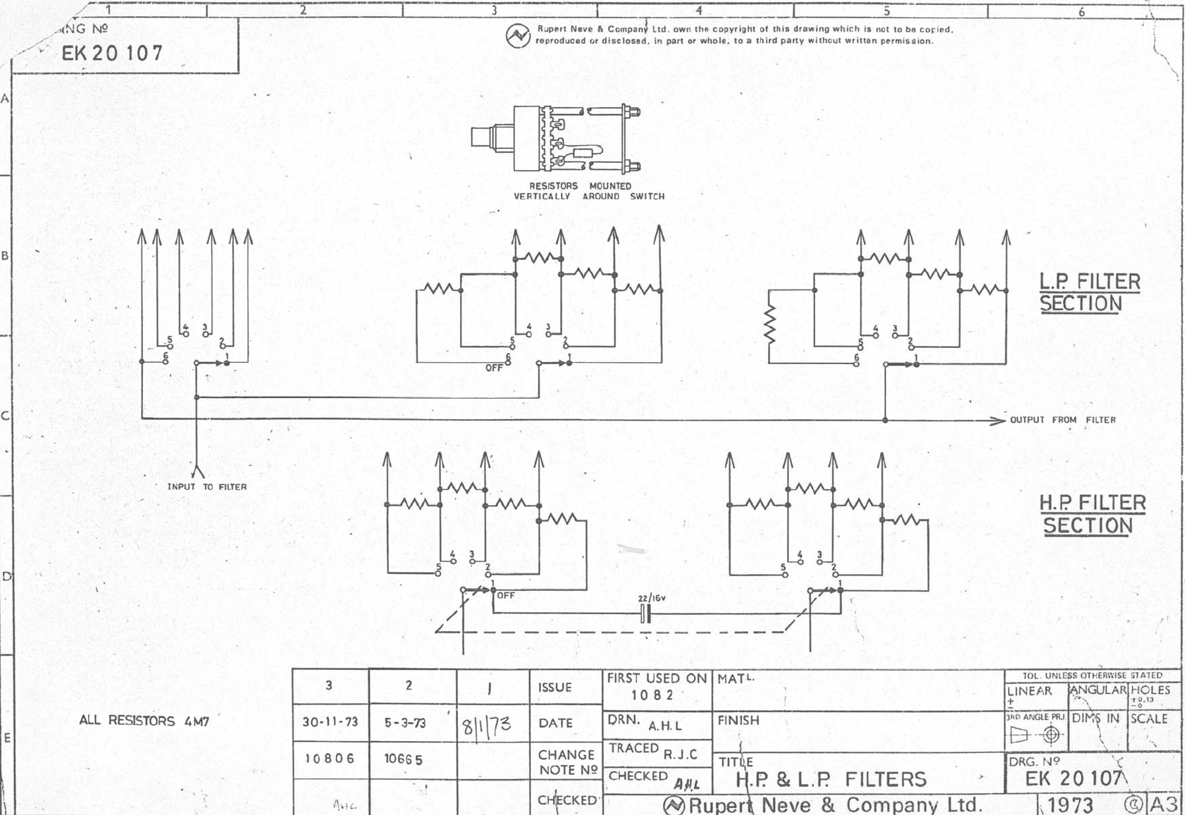
HP/LP Filter Switch (PL20107) EK20107 Wiring Diagram
User Guide Is sue 3 Page 14
1073 & 1084 Chan nel Am pli fiers Ser vice In for ma tion
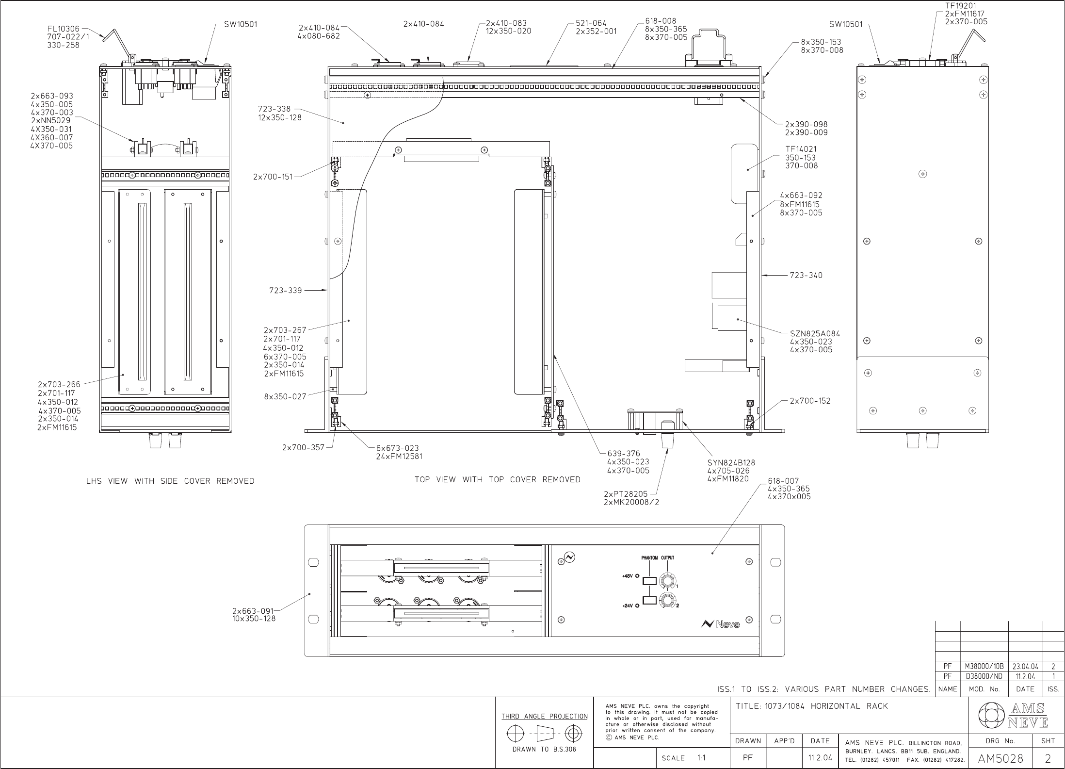
Title: 1073/1084 Horizontal Rack Schedule Nr: AM5028
3 August, 2004 Page:
3
Issue: 1
CABLE FROM:- ROUTING TO:-
Code Type Colour Pin Connector Location Signal Length Comment Pin Connector Location
310-183 24/0.2 Green/Yellow E 330-071 IEC Stud 330-454 Safety Earth
310-183 24/0.2 Green/Yellow 330-069 Chassis Stud 330-454 Safety Earth
310-047 16/0.2 Brown L 330-071 IEC Sleeve with 1A 330-071 Switch
310-052 16/0.2 Blue N 330-071 IEC WA12005 2A 330-071 Switch
Yellow TF14021 1 CN20013 Switch
Yellow TF14021 Centre Solder TF19201
310-052 16/0.2 Blue 1(1of2) Solder TF19201 2 330-071 Switch
Black TF14021 1(2of2) Solder TF19201
Brown TF14021 3 Solder TF19201
Green TF14021 2 Solder TF19201
Blue TF14021 4(1of3) Solder TF19201
310-046 16/0.2 Black 4(2of3) Solder TF19201 4(2of3) Solder TF19201
Red TF14021 4(3of3) Solder TF19201
Orange TF14021 6 Solder TF19201
Violet TF14021 5 Solder TF19201
Grey TF14021 7 Solder TF19201
White TF14021 3 J1 (25VAC) SZN825A084
White TF14021 4 J1 (25VAC)
310-052 16/0.2 Blue 2 SZN825A084 Bolt 330-069 Chassis
310-031 7/0.2 Orange 1 420-691 Housing CN2 2+3 solder via 6K8 Res’s Mic In Ch1 XLR
310-031 7/0.2 Orange 9 420-612 Contacts SYN824B12
8
2+3 solder via 6K8 Res’s Mic In Ch2 XLR