Amtek System AIRT20XQMKG2 Tablet PC User Manual
Amtek System Co., Ltd. Tablet PC
user manual
1

i
Preface
Copyright 2004
All Rights Reserved.
The information in this document is subject to change without prior notice in order to improve reliability, design
and function and does not represent a commitment on the part of the manufacturer.
In no event will the manufacturer be liable for direct, indirect, special, incidental, or consequential damages arising
out of the use or inability to use the product or documentation, even if advised of the possibility of such damages.
This document contains proprietary information protected by copyright. All rights are reserved. No part of this
manual may be reproduced by any mechanical, electronic, or other means in any form without prior written
permission of the manufacturer.
Safety Notices
1. Please read these safety instructions carefully.
2. All precautions and warnings on the equipment should be carefully noted.
3. Please disconnect the computer from the AC outlet before cleaning.
4. Never pour any liquids into any openings or directly onto the computer unit. This could result in fire or electrical
shock.
ii
5. Ensure the voltage range of the power outlet is between 100V and 240V before connecting the computer unit.
Exceeding the maximum rated voltage may cause damage to the AC adapter or to the computer. This could result in
fire or electrical shock.
6. Do not leave this equipment in a non-temperature controlled environment; storage temperatures below 4°C (39°F)
or above 40°C (104°F) may damage the unit.
To reduce the risk of an electric shock, which could cause personal injury, please follow all
safety notices. The symbols shown are used in your documentation and on your equipment to
indicate safety hazards.
Lithium batteries can be dangerous. Danger of explosion if battery is incorrectly replaced.
Replace only with the same or equivalent type recommended by the manufacturer. Dispose of
used batteries according to the manufacturer’s instructions.

iii
Under no circumstances should the user attempt to disassemble the power supply. The power
supply has no user-replaceable parts. Inside the power supply are hazardous voltages that can
cause serious personal injury. A defective power supply must be returned to your dealer.
Safety Notices for the Power Cord
This equipment has a 2 or 3-wire power cord. Replace the power cord if it becomes damaged. Contact your dealer
for an exact replacement.
In the U.S.A. and Canada, the power cord must be a UL-listed detachable power cord (in Canada, CSA-certified).
2-wire cord SPT-2 18AWG
3-wire cord SVT or SJT, 18 AWG, 3-conductor
Provided with a molded-on cord connector body at the other end. The cord length must not exceed 3 meters.
Outside the U.S.A. and Canada, the plug must be rated for 250 VAC, 2.5 amp minimum, and must display an
international agency approval marking. The cord must be suitable for use in the end-user’s country. Consult your
dealer or the local electrical authorities if you are unsure of the type of power cord to use in your country. Voltage
changes occur automatically in the power supply.

iv
Note-TNV Safety Caution
To reduce the risk of fire, use only No. 26 AWG or larger telecommunication line cord. Avoid
using a telephone (other than a cordless type) during an electrical storm. There may be a remote
risk of electric shock from lightning. Do not use the telephone to report a gas leak in the vicinity
of the leak.
Notice of EMC Compliance
This equipment has been tested and found to comply with the limits for a Class B digital device, pursuant to Part 15
of the FCC Rules. These limits are designed to provide reasonable protection against harmful interference in a
residential installation. This equipment generates, uses, and can radiate radio frequency energy and if not installed
and used in accordance with the instruction manual may cause harmful interference to radio communications.
However, there is no guarantee that interference will not occur in a particular installation. If this equipment does
cause harmful interference to radio or television reception, which can be determined by turning the equipment off
and on, the user is encouraged to try to correct the interference by one or more of the following measures:
Reorient or relocate the receiving antenna.
Increase the separation between the equipment and receiver.
Connect the equipment into an outlet on a circuit different from that to which the receiver is connected.
Consult the dealer or an experienced technician for help.
RF exposure warning ·
The equipment complies with FCC RF exposure limits set forth for an uncontrolled
environment.
The equipment must not be co-located or operating in conjunction with
any other antenna or transmitter.
Max. SAR Measurement (1g)
802.11b: 0.264 W/kg
802.11g: 0.188 W/kg

v
Use only shielded I/O cables to connect I/O devices to this equipment.
You are cautioned the changes or modifications not expressly approved by the party responsible for compliance
could void your authority to use the equipment.
Canadian EMI Compliance Statement
This Class B digital apparatus meets all requirements of the Canadian Interference - Causing Equipment
Regulations.
European Union CE Marking Declaration
This product has been tested and found to comply with the EMC requirement subject to the EU directive for CE
marking.
FCC Statement to Users for the FaxModem
This equipment complies with Part 68 of the FCC rules. On the bottom of this equipment is the label that contains,
among other information, the FCC Registration Number and Ringer Equivalence Number for this equipment. IF
REQUESTED, THIS INFORMATION MUST BE GIVEN TO THE TELEPHONE COMPANY.
The REN is useful to determine the number of devices you may connect to your telephone line and still have all of
those devices ring when your telephone number is called. In most, but not all areas, the sum of the REN’s of all
devices connected to one line should not exceed five (5.0).
To be certain of the number of devices you may connect to your line, as determined by the REN, you should
contact your local telephone company to determine the maximum REN for your calling area.
If your telephone equipment causes harm to the telephone network, the telephone company may disconnect your
service temporarily. If possible, they will notify you in advance. But if advance notice isn’t practical, you will be
informed of your right to file a complaint with the FCC.
Your telephone company may make changes in its facilities, equipment, operations or procedures that could affect
the proper functioning of your equipment. If they do, you will be notified in advance to give you an opportunity to
maintain uninterrupted telephone service.
The telephone company may ask you to disconnect this equipment from the network until the problem has been
corrected or until you are sure that the equipment is not malfunctioning. This equipment may not be used on coin
service provided by the telephone company.

vi
The Telephone Consumer Protection Act of 1991 makes it unlawful for any person to use a computer or their
electronic device to send any message via a telephone facsimile machine unless such message clearly contains in a
margin at the top or bottom of each transmitted page or on the first page of the transmission the following
information:
The date and time of transmission
Identification of either business, business entity or individual sending the message;
Telephone number of either the sending machine, business entity or individual.
In order to program this information into your fax/modem, please refer to the appropriate instructions in your
fax/modem manual.
This transmitter must not be co-located or operating in conjunction with any other antenna or transmitter.

vii
Laser Compliance Statement for CD-ROM, DVD-ROM, CD-RW and DVD/CD-RW Combo Drives
The CD-ROM, DVD-ROM, CD-RW and DVD/CD-RW Combo drive for this computer are laser products. The
classification label of the drive is located on the bottom of the drive. Below is a sample of the classification label;
CLASS 1 LASER PRODUCT
LASER KLASSE 1
LOUKAN 1 LASERLAITE
APPAREIL A LASER DE CLASSE 1
KLASS 1 LASER APPARAT
The drive is certified in the USA to comply with the requirements of the Department of Health and Human Services
21 Code of Federal Regulations (DHHS 21 CFR) Subchapter J. for Class 1 laser products.
In other countries the drive is certified to comply with the requirements of EN60825.

viii
Do not open the drive. There are no user-serviceable parts or components inside. Use of controls,
adjustments and operation of procedures other than those specified, may result in hazardous
exposure to radiation. Class I (1) laser products are not considered hazardous. The drive has an
internal, Class I (1), 0.5-milliwatt, aluminum gallium-arsenide laser that operates at a wavelength
of 760 to 810 nanometers. The design of the laser system and the drive ensures that there is no
exposure to laser radiation above a Class I (1) level during normal operation, user maintenance or
servicing.
Table of Contents
Chapter 1 Before You Start ...............................................1
Important Things to Remember Before Working on Your Computer 2
Chapter 2 Introduction ......................................................5
Introducing your Computer ........................................................... 6
Unpacking the Computer............................................................... 6
Getting to Know Your Computer .................................................. 7
Chapter 3 Getting Started ................................................15

ix
Setting Up the Computer............................................................. 16
Inserting and Removing the Battery Pack ................................... 16
Operating on Battery Power ........................................................ 18
Chapter 4 Using the Computer........................................21
Adjusting the Screen Display ...................................................... 22
CF Cards and Expansion Sockets ................................................ 24
The Battery Power System .......................................................... 24
Using the A-Menu....................................................................... 27
Entering Information with the Pen .............................................. 28
Rotating your Display ................................................................. 30
Using the OnScreen Keypad ....................................................... 30
Chapter 5 Performing Desktop Operations on Your Computer 33
Audio .......................................................................................... 34
Connecting Peripheral Devices ................................................... 35
Chapter 6 Software Utilities ............................................37
Recovery CD Installation ............................................................ 38
Using the Support CD ................................................................. 40
Utilities ....................................................................................... 42
Chapter 7 Troubleshooting..............................................52
General Hardware Problems/Possible Cause and Solution .......... 53
Contacting Your Dealer .............................................................. 56
Chapter 8 How do I Expand my Computer? ...................58
How to upgrade your RAM module ............................................ 59
Easy to Upgrade HDD Module.................................................... 60

x
Appdendix Specifications ................................................66
Detailed Specifications................................................................ 67
1
Before You Start
2
This manual will help you get the most from your computer.
If you are a less experienced user, you should read through
the manual carefully before using your computer.
Important Things to Remember Before Working on Your
Computer
Let your Computer acclimatize itself
Rapid changes in temperature such as those from the cold outdoors to a
warm office would not be suitable for your system.
Do not power up your system immediately if it has been
exposed to hot or cold conditions. Instead, allow the system
to adjust gradually to room temperature over a three to four
hour period.
Placement of your Computer
Choose a suitable place for your system that’s not too hot, too cold, too
dark, or too bright. Glare can make it difficult to read the screen.
Allow sufficient air circulation around the computer when you are
working indoors
Try to keep the system components from being destroyed if it is over
heated
Do not block the ventilation opening

3
Do not place your computer in direct sunlight
Suitable place to work
Your computer will run well under most conditions but avoid extreme
temperatures and humidity levels.
There are some things you can tolerate that the computer can’t – things
like static electricity, dust, water, steam and oil.
A lithium-ion battery pack is included for those who are
frequent travelers. When you are running your computer on
battery power for the first time, remove the battery from the
package, install it into the system and recharge the battery
to fully prepare for service.

4
Intentionally Left Blank

5
Introduction

6
Introducing your Computer
Your computer features the latest advances in portable computing
technology. The computer modular design provides maximum
expandability without compromising portability. One CF card slot gives
you the ability to use standard CF cards or memory cards.
Unpacking the Computer
The computer comes securely packaged in a shipping carton. Please
contact your dealer if you find that anything is missing or damaged
after examining the contents. The shipping carton should contain the
following items:
Power cord
Support CD
Carrying bag
Battery Pack
Stand (Optional)
AC/DC adapter
User’s manual, Recover CDs
Do not throw the packaging materials away. You may need them later if
you have to ship the computer.
Because of different configurations, some of the features
mentioned in this manual might not be included on your
computer or may differ slightly.
7
Getting to Know Your Computer
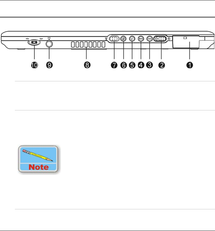
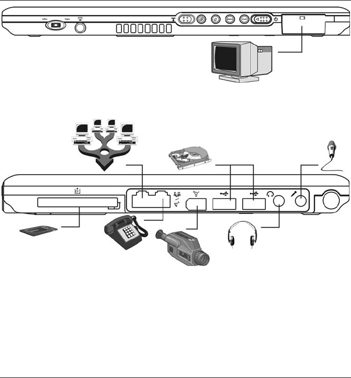
The Front View
1. External CRT Port
This port allows you to easily connect an external display
monitor into your computer using the 15-pin female connector.
2. Power Switch
Slide and release the power switch for 1 to 2 seconds will turn
on the computer (the LED will lit to indicate its present status).
You can also slide this switch to resume normal status when the
computer is in suspend mode.
In case your computer crash, we recommend you to slide
and release the power switch for 4 to 6 seconds will force
the system to shutdown.
3. Secure Attention Sequence(SAS)
A computer without an attached keyboard must support an SAS

8
hardware mechanism to generate the SAS which also known as
“CTRL-ALT-DEL” or “CAD”.
4. Menu Button
Use this key to enable the A-Menu display function
5. Internet Explorer Button
Use this key to open the Internet Explorer.
6. Rotate Button
Use this function to switch your screen display between portrait
or landscape orientation.
7. Wireless Switch
Use this switch to turn off the wireless function of your system.
8. Ventilation Opening
Please do not block this opening when the system is in
operation.
9. DC IN Jack
Plug the AC adapter into this jack.
10. Jog dial
Functions like enter and the up and down arrow keys on a
standard keyboard.
Press inward to enter .
Rotate upward to scroll up.
Rotate downward to scroll down.
9
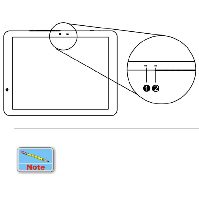
LED Indicator
1. Battery Charge
This indicator will light up when the battery is charging. It also
indicates when the computer enters suspend mode.
Under suspend mode, the power LED will start blinking while
the battery LED will stay lighted. The Battery LED is orange
while the battery pack is charging. When the battery pack is
fully charged, the Battery LED will turn green.

10
For more detailed information, please refer to “The Battery
Power System” in Chapter 4.
2. HDD LED
Indicates that the computer is accessing the hard disk drive.
The Left View
1. Port Replicator Stand Supporter
Connect these two holes into the Docking Station that will serve
as supporter for the system.
2. Speaker
This will serve as sound output for the system.
The Rear View
1. Kensington Lock
Allows you to connect a special computer lock to secure your
computer. You can purchase a lock at most computer retailers.
11
2. Speaker
This will serve as sound output for the system.
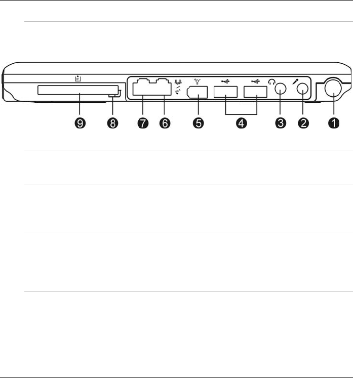
The Right View
1. Pen Holder
Secures the pen to the system.
2. Microphone Input
This jack is used to input audio from other devices, such as a
radio or tape recorder, into your computer.
3. Audio Line Out
You can plug in an external speaker or headphone, or connect
the line out jack to an audio device such as a cassette recorder
to record the computer’s audio output.
4. USB Port
Your computer includes two Universal Serial Bus (USB) 2.0
ports. USB2.0 is the latest development in Plug and Play
technology.

12
5. IEEE 1394 Port
A fast external bus standard that supports data transfer rates of
up to 400 Mbps (400 million bits per second). Can be used to
connect up to 63 external devices. Also supports isochronous
data -- delivering data at a guaranteed rate.
This makes it ideal for devices that need to transfer high levels
of data in real-time, such as video devices. Also supports both
Plug-and-Play and hot plugging, and provides power to
peripheral devices.
6. Modem
This jack connects to an internal 56K voice/fax/data modem.
Connect your computer to your phone line through this port.
7. LAN
This jack provides a standard RJ-45 connection to an existing
network or a high-speed (DSL or cable) connection via a
network cable.
When using a LAN, please use an EMI Shielding Cable to
minimize inteference when transmitting.
8. CF Card Eject Button
Ejects an optional CF Card from the CF Card slot.
13
9. CF Card Slot
Supports an optional Type I or Type II CF card or memory Card.
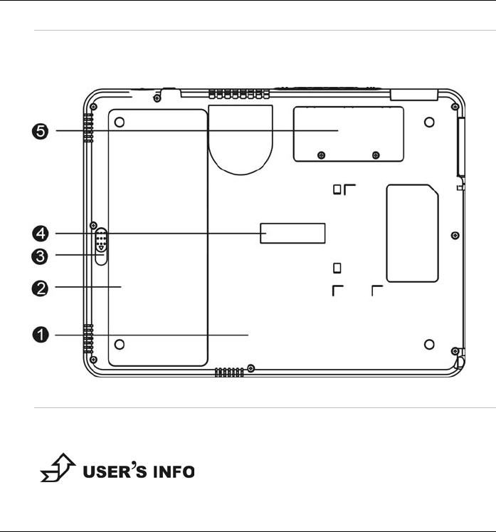
The Bottom Panel
1. HDD Compartment
Your computer includes a 2.5-inch IDE hard disk drive (9.5mm
in height).
For upgrading, please refer to Chapter 8 on “How do I
Expand my computer”.

14
2. Battery
Your computer comes equipped with a factory-installed battery
pack module. After the battery runs down, the module can be
removed and replaced with a charged battery.
3. Battery Release Latch
Use this latch to release the battery from its bay.
4. Port Replicator Connector (Optional)
Connect the optional Port Replicator to the100-pin Port
Replicator connector. The Port Replicator further enhances
your computer’s portability by making it easy for you to connect
and disconnect peripheral devices to your computer.
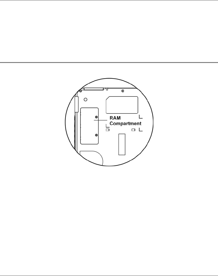
5. RAM Module Compartment
This compartment will allow for upgrading your system DDR-
RAM.
For upgrading, please refer to Chapter 8 on “How do I
Expand my computer”.
15
Getting Started
16
Setting Up the Computer
Remove the computer from its package.
Insert the battery pack into the computer so the pack can start
charging. (Please refer to the “ Inserting and Removing the Battery
Pack “section.)
Connect the computer to an external power source. Turn on the
computer.
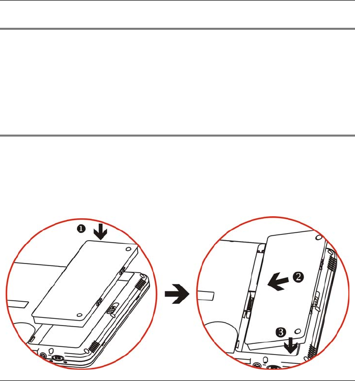
Inserting and Removing the Battery Pack
Inserting the Battery Pack
Turn over the computer and place it on a solid, flat surface.
Align the battery into the battery compartment (1).
Place the battery into the bay at a slight angle of 45 degree as
illustrated in (2).
17
The front edge of the battery should slide into the grooves in the
battery compartment as indicated in the illustration (3).
After it is securely fitted into the grooves, gently lower the battery
into the bay until it clicks securely in the bay.
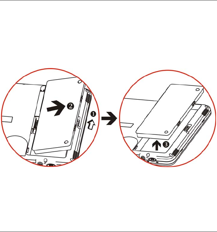
Removing the Battery Pack
Turn off the computer and disconnect the AC adapter.
Turn it over and place it on a solid, flat surface.
Use your thumbs to pull the latch into the direction of the arrow (1) to
release the battery from the bay.
The battery will now be angled slightly out of the bay (2).
Pull the battery out (3) to completely release from the battery
compartment.
18
Connecting the Computer to an External Power Source
To connect the computer to an external AC power source using the AC
adapter:
Plug the AC adapter cable into the AC power connector on the
computer.
Plug one end of the power cord into an electrical outlet and the other
end into the AC adapter.
To prevent damage to your computer, please do not use
inferior extension cords. An AC adapter comes with your
computer. Never use a different kind of adapter to power
the computer or other electrical devices.
Whenever possible, keep the AC adapter plugged into the computer and
an electrical outlet to recharge the battery.
Don’t try to reset your computer while the hard disk is in use
as it may result in the loss or destruction of your data.
Operating on Battery Power
Your computer comes with a rechargeable battery pack that lets you
operate the computer without an external power source.

19
When the battery pack is fully charged, you can operate the computer
for approximately 3.5 hours/40Wh pack under typical condition.
Charging the Battery Pack
The installed battery pack charges automatically whenever the
computer is connected to the AC adapter and an external power source.
The first time you use the battery, be sure to fully discharge the battery
and recharge it until it is fully charged.

20
Intentionally Left Blank
21
Using the Computer
22
Adjusting the Screen Display
External CRT Display
You can connect an external monitor through the 15-pin CRT connector.
Four configurations are available:
Monitor
Notebook
Intel ® Dual Display Clone = Monitor + Notebook
Extended Desktop = Panel + Extended CRT
Please refer to the “VGA Utility” section in Chapter 6.
The Computer’s Hot Key Controls
The computer provides you with special hot keys to execute all the
major functions that you like to run on your computer.
Power Switch – Slide this button for 1-2 seconds to power on or
enter the suspend/resume mode. Slide this button for more than 4
seconds to power off the system.
SAS Button – Press this button to implement the “Ctrl-Alt-Del”
function.
Menu Button - Press this button to implement the “A-Menu”
function.
Internet Button - Open Internet Explorer short-cut key

23
Rotate Button - Switch your screen display between portrait and
landscape orientations.
Wireless Switch - Turn the radio on and off.

24
CF Cards and Expansion Sockets
The computer features one CF expansion socket designed to interface
with a Type I or Type II CF card.
Inserting a CF Card
The computer will emit a tone followed by a higher tone when a CF
card is inserted. When you eject a card, the computer will emit a high
tone followed by a lower tone. Cards can be inserted and removed
whether your system is on or off. Follow these instructions to insert a
CF card:
Hold the CF card with the arrow side up and the connector side
toward the socket.
Align the card connectors with the socket and carefully slide it into
the socket until it locks into place.
The Battery Power System
Before using the computer on battery power for the first time,
disconnect the power adapter and check the battery status icon on the
Windows Toolbar to make sure the battery is fully charged.
Removing the Battery Pack
To remove the battery pack from its compartment, please refer to
Chapter 3,” Inserting and Removing the Battery Pack”.

25
Preparing the Battery Pack for Use
Before using the battery pack for the first time, the Smart Battery IC
within the battery pack should be calibrated in order to get accurate
reporting of the remaining battery life status.
To calibrate the battery pack, follow the instructions below:
Turn the computer off. Connect the AC adapter and let the battery
fully recharge. When the battery charge LED turns from orange to
green, the battery is fully charged.
Turn On the computer and let the battery run down until the battery is
low-low and you hear continuous warning beeps. The system will
automatically enter the Suspend mode. You can now connect the AC
adapter.
The battery pack is now properly calibrated.
In general, using the battery until the low battery warning indicator
appears and fully recharging the battery each time (full
discharge/charge cycle) will ensure the accuracy of the battery status
gauge.
Automatic Battery Pack Charging Function
You can automatically charge the battery pack by using the AC Adapter.
The charge time is almost two hours when the computer
power is turned off.

26
Battery Status
Windows XP has an applet in the Control Panel that will display an
icon in the Windows taskbar indicating when the computer is running
on battery power or is attached to the AC adapter.
This applet also displays a meter that indicates how much charge
is remaining in the battery.
Battery Low Warning
A beeping sound every 1.5 seconds alert you on the “Battery Low”
status. When the battery power reaches the “Battery Very Low” status
the beeping sound will accelerate.
Your battery now has 1 ~ 2 minutes of battery charge left. You must
save your data or connect AC power immediately; otherwise, you may
lose your data.
Beeping accelerates - Battery Very Low: Indicates that there are 1 to
2 minutes of battery charge left. Save your work and turn off the
computer or connect the AC adapter.
When there is only one minute of battery charge left, the computer will
suspend to the HDD and power off. Connect AC power and resume
your work.
Small Battery for the Real Time Clock
There is a small built-in battery pack that supplies power to the system
in order to maintain certain system information while the power is off.
If the computer is left without a power source for long period of time,
this battery will be exhausted and system information will be lost.
27
To avoid damage, only use replacement batteries
recommended by System provider. To prevent the loss of
data when the system loses power, do not remove the
battery pack while the power is on.
Using the A-Menu
Press the “Menu” button located on the side of the Tablet PC to display
the “A-Menu” window dialog box.
Some of the most popular functions can be accessed from
this menu.
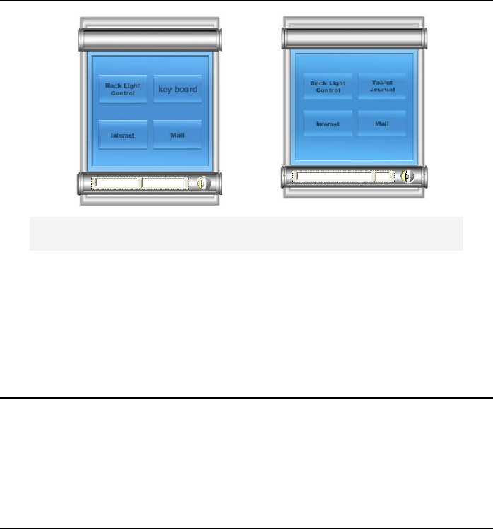
28
(1) (2)
(1) Left graphic is for Windows XP Home Edition/Professional
(2) Right graphic is for Windows XP Tablet PC Edition
Adjusting the Brightness
The brightness can be adjusted using the selection provided by the A-
Menu. Choose “Back Light control” to adjust the brightness of your
screen.
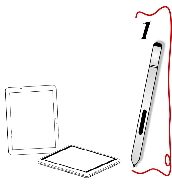
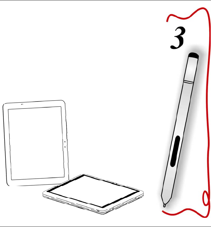
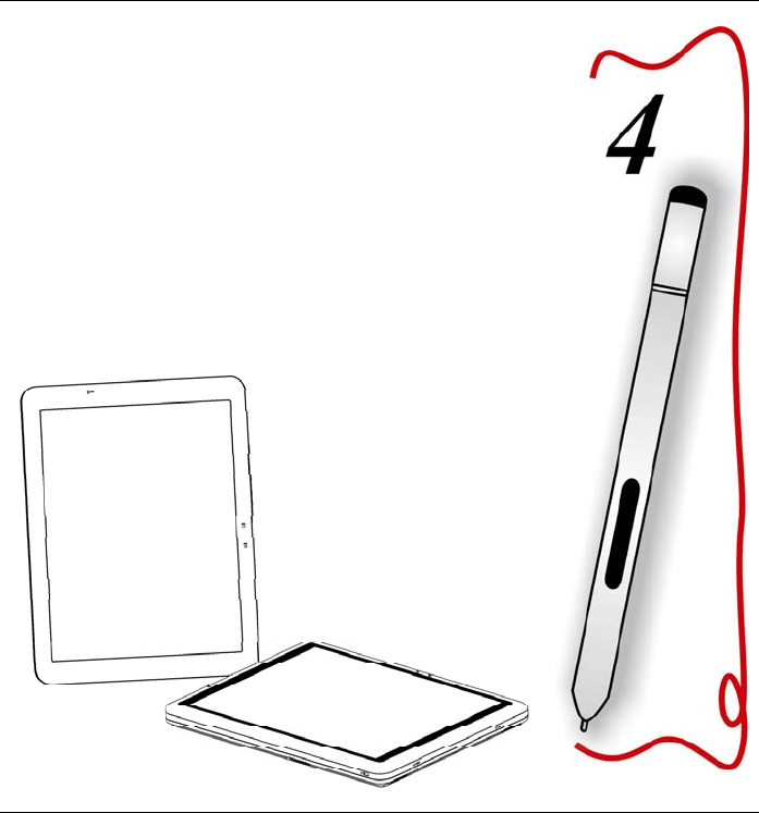
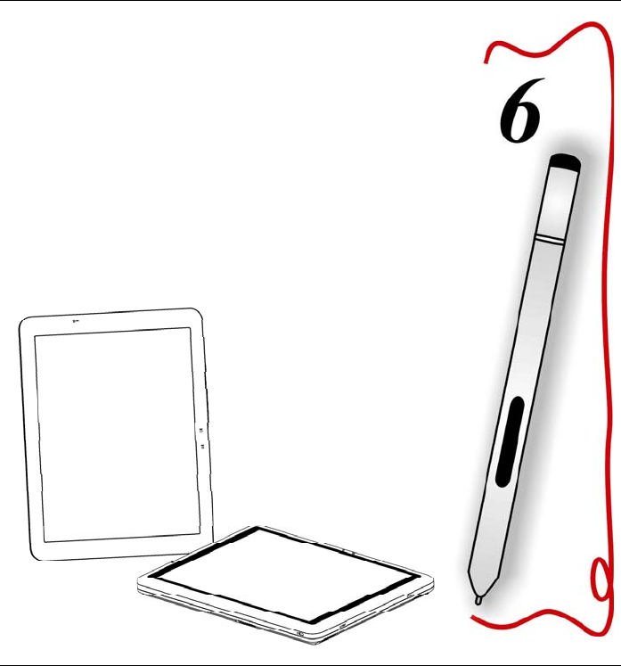
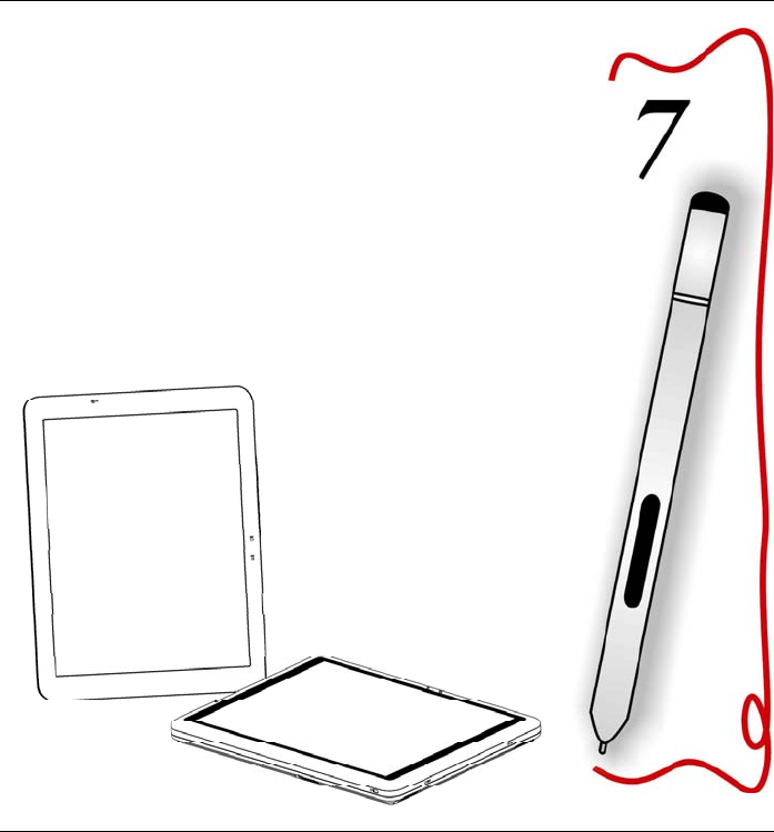
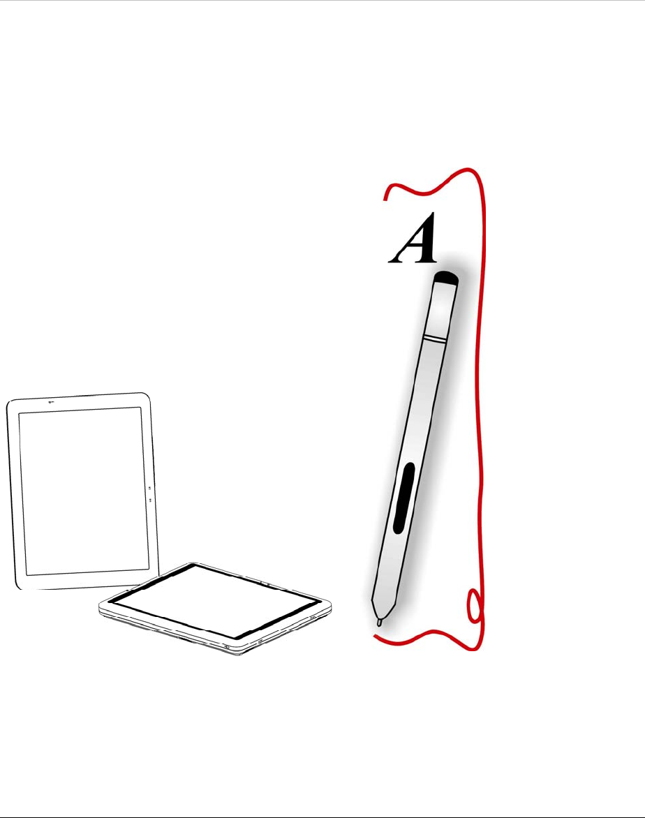
Entering Information with the Pen
There are two types of pen available for your system:
Stylus Pen (For Digitizer System)
29
Stylus Pen
Hold the pen as if you were writing with a standard pen or pencil.
Position your hand on the pen so that you will not accidentally press the
pen button.
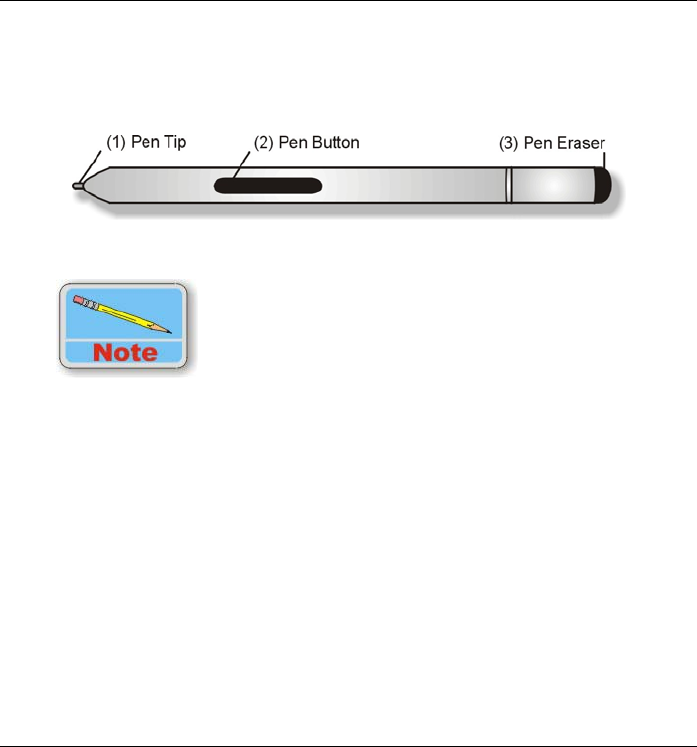
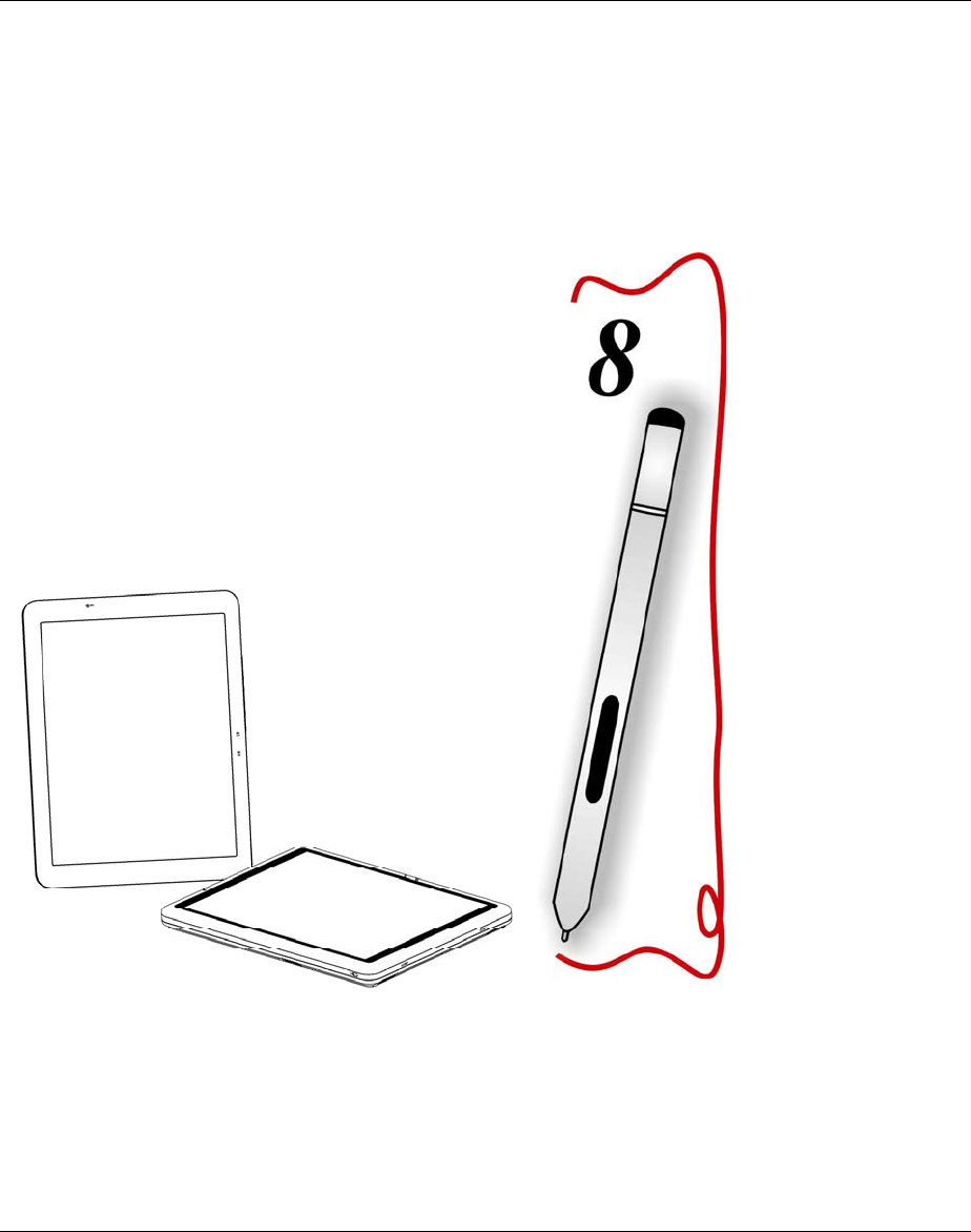
Identifying the Pen Tip and Pen Button of Stylus Pen
As you monitor the movements of the pen, focus on the
pointer on the screen, not on the tip of the pen.
30
Pen Components
Pen tip - Interacts with the Tablet PC whenever the tip is touching the
screen. When tapped on or held over a pen-activated button it
activates the button.
Pen button - Functions like the right button on a mouse.
Pen Eraser - Use this eraser to delete information the same way you
use the backspace key of your keyboard.
Rotating your Display
Your computer allows you to switch your screen display between
portrait and landscape orientation.
Rotation button – You can use this function to rotate your screen
into portrait or landscape mode.
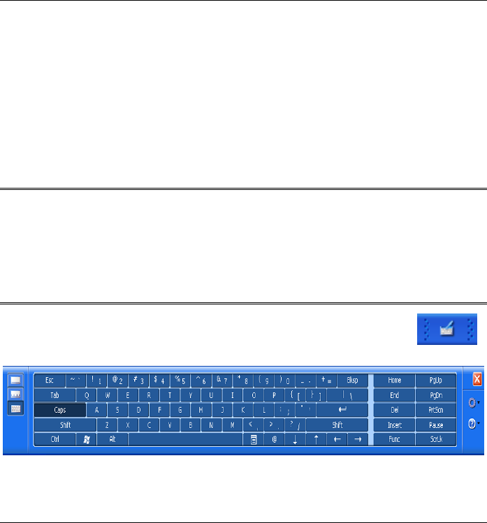
Using the OnScreen Keypad
Select the Keyboard via the "Tablet PC Input Panel" icon " "
and use the pen to tap on the onscreen keypad.
Windows XP Tablet PC Edition
Select the keyboard via A-MENU and use the pen to tap on the
onscreen keypad.
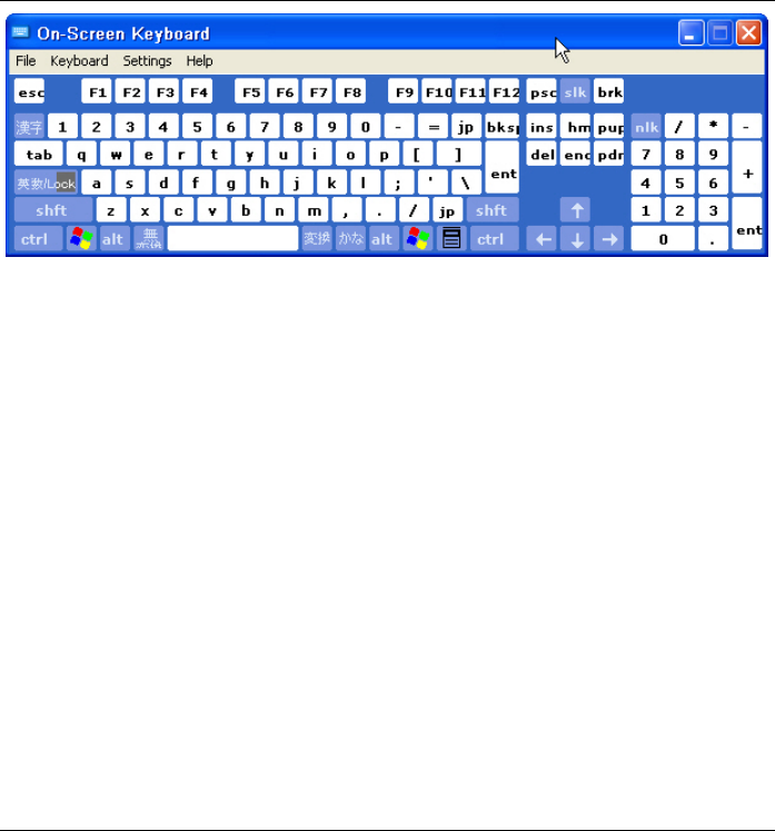
31
Windows XP Home Edition/Professional

32
33
Performing Desktop
Operations on Your
Computer

34
This chapter will discuss some of the major functions that are typical of
a desktop system.
Audio
Multimedia Sound System
Your computer is equipped with internal stereo speakers, a microphone
and input audio ports for external audio devices.
Audio Software
Your computer comes equipped with an integrated sound system
capable of providing you with quality audio sound through the built-in
speakers or through external speakers connected via the system ports.
Audio Volume Control
The volume can be adjusted using the adjustment provided by A-Menu.
Choose the “Volume” control to adjust the volume of the system.
Playing Audio Files
Your computer can play audio files stored in MIDI, WAVE or MP3 file
formats. Check the Help and Support Center in Windows for
information on the functions of the Media Player.
External Speakers and Microphone
The sound system is capable of providing high-quality sound to
external speakers and receiving and of processing sounds from an
external microphone or external sound source.

35
Connecting Peripheral Devices
Connecting an External Monitor - This machine allows you to
connect to an external monitor via the VGA port.
Connecting USB Devices - USB devices are Plug & Play; simply
plug the USB device into any USB port on the computer to use it.
There are some exceptions; the OS will not support some devices.
Connecting IEEE 1394 Devices – IEEE 1394 is a very common
transfer interface widely used in many audiovisual devices.
If the OS you use does not recognize the 1394 devices you plan to use,
please follow the instructions in the manual to install the proper
drivers or software applications to make the devices work.
Connecting to a network - The illustration only shows how to
connect the computer to the network. The actual application and
setting should be done following the instructions in the OS manual, or
you should ask for a technician’s professional assistance.
Installing the modem - Use a phone cable to connect the slot on the
modem to the phone jack.
The hardware installation is complete. Then follow the instructions
from your ISP (Internet Service Provider) to make the proper
connection to the Internet.
Connect peripheral devices to the computer's interface ports as shown
below:
36
37
Software Utilities

38
This chapter deals with installing the drivers and utilities essential to
the operation or improvement of some of the computer’s subsystems.
Recovery CD Installation
Restoring Software
The Tablet PC includes “Recover CD” that contains all the software
shipped and pre-installed or preloaded with simple instructions to
restore it.
We recommend you to use the Recover CD to recover your
system in case you system crash.
Setting Up Your Hardware
You can insert the “Recover CD” into any external CD-ROM drive
whether it is USB or IEEE 1394 based interface.
To navigate on the “Recover CD” software, you can use an optional
USB external keyboard or Jog dial.
Using the System Recovery CDs
The “Recover CD” is included in all models to let you restore back to
the original factory default setting. This default setting is the software
installed in your system before the shipment of the computer.
After the restoration from the “Recover CD”:
All settings are set back to the original default settings.
All software is factory default.
39
No software, including drivers, applications, and utilities that you
may have installed are present after the initial setup.
You may use the “Recover CD” as bootable CD to start the Tablet PC
in case it is not functioning.
In case of unsuccessful restoration or installation that may lead to loss
of data; to prevent this, read the 2 cautions before using the “Recover
CD”. Please refer to the documentation included in the CDs for more
detailed information on using the “Recover CD”. If the tablet PC does
not function, you can start the system using the “System Recover CD”;
the CD is bootable.
To prevent any loss of data, please back your files to your
hard drive before re-installing the operating systm using the
“System Recover CD”.
In case there is a serious damage or an unsuccessful
restoration or installation on your Tablet PC, use the “Recover
CD” to prevent it only if the system is connected to a reliable
external power or AC adapter or optional docking station or DC
cable. We don’t recommend you to use the “Recover CD” during
a power failure or running on battery power or connected to an
optional Auto/Air cable or Automobile Power adapter/charger.
40
During restoration
Do not interrupt the power on the tablet PC by unplugging or
undocking the tablet PC.
Do not shut down the tablet PC.
Using the Support CD
The Support CD contains the drivers and utilities necessary for the
proper operation of the computer based what you need to install
according to your choice of operating system.
Drivers and utilities from Support CD are already installed on
your computer. Only use it to reinstall the software.
Driver Operating System Support
• VGA
• Audio
• A-Menu
• Chipset Utility
• Modem
• Wireless Utility
Windows XP Tablet PC Edition
Windows XP Home Edition
Windows XP Professional
Driver Installation
Drivers can be installed using the AutoRun installation.
Use the step-by-step procedures to execute the “AutoRun”
application by selecting “Driver Installation” on the CD disk that
comes with your package

41
This section describes the operation and installation of
drivers supplied on the Driver Utility CD-ROM that is shipped
with your computer.
Installing VGA/Audio/A-Menu/Chipset Utility/Modem Drivers
Please follow the installation procedure to install driver and utilities.
Insert the Support CD into your CD drive. Click “Start” and select
“Run”.
Type the following: D:\Driver\VGA or Audio or A-Menu or
Chipset Utility or Modem (where D represents your CD drive).
Click on “Setup.exe” to begin the Installation Wizard. Follow the
Wizard’s on-screen instructions to complete the installation.
Restart the system.
Installing the Wireless LAN Driver
Please follow the installation procedure as listed to install driver and
utilities. Please follow these instructions to install the Wireless LAN
driver:
Insert the Support CD into your CD drive. Click “Start” and select
“Run”.
Type the following: D:\Driver\Wireless\ (where D represents your
CD drive).
Click on “SetupWLD.exe” to begin the Installation Wizard. Follow
the Wizard’s on-screen instructions to complete the installation.
Restart the system.

42
Utilities
This section describes the utilities essential to the operation with
your computer.
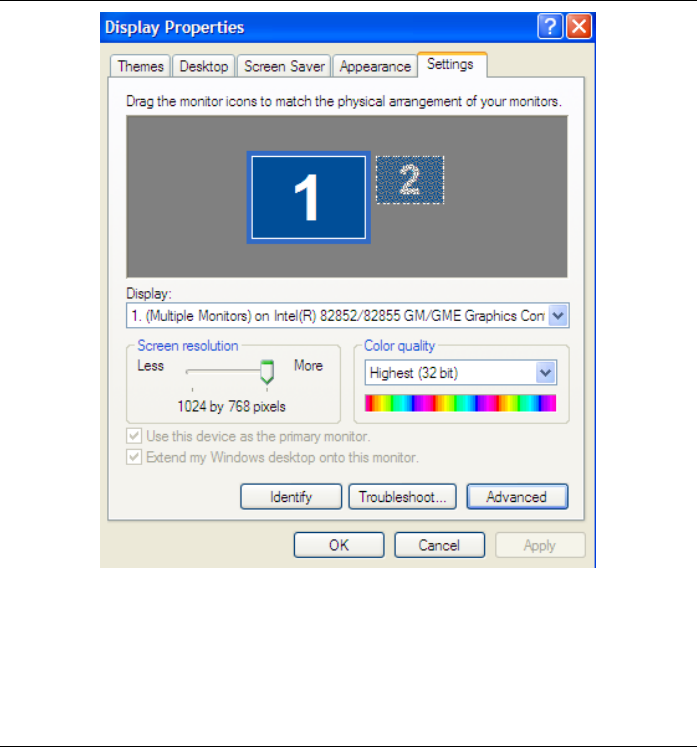
VGA Utility
After you have restarted Windows, open the “Control Panel” and
double click on the “Display” icon. From the “Display Properties”
window, select the “Settings” tab and click on the “Advanced” tab to
enter the "INTEL VGA Utility" window.
43
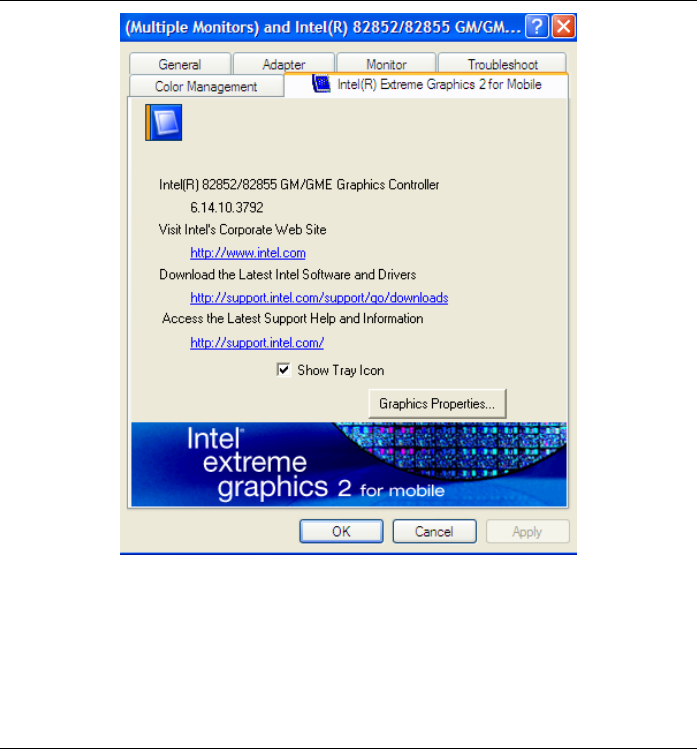
Select “Intel® Extreme Graphics 2 for mobile”
Click the “Graphics Properties”
44
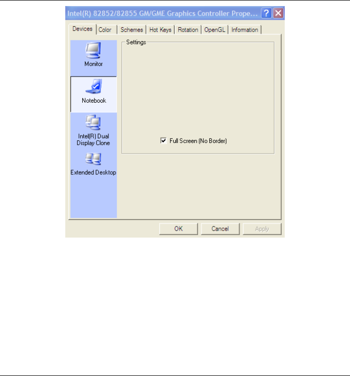
Display Control
The VGA utilities allow four simultaneous outputs to Monitor
(External), Notebook (Tablet PC), Dual Display Clone (External +
Tablet PC) and Extended Desktop. Before proceeding, be sure the
monitor is connected to the computer.
45
Type/State
This applies to the display that you prefer to use.
Select the "Monitor" if you want the picture to display only on the
external monitor screen.
Select "Notebook" if you want the picture to display only on the
Tablet PC’s screen.
Select “Intel® Dual Display Clone” if you want the picture to
display on both the Tablet PC and the external monitor.

46
Select “Extended Desktop” if you want to extend your screen on the
external monitor.

47
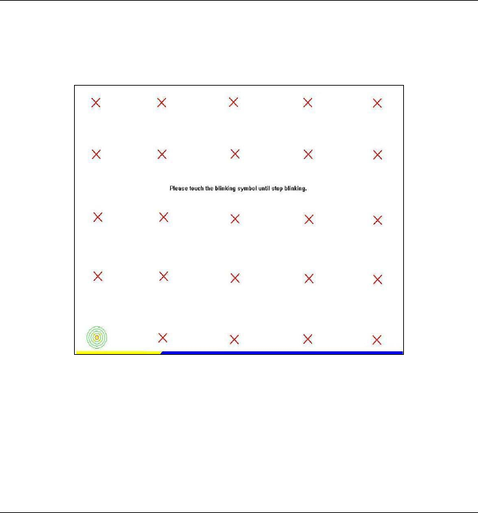
Calibration
If your cursor pointer does not function well, you can select the
“General” tap “4 pts Cal” button or “Advanced -> 25 pts Cal” button
and click it to correct point locations.
< 4 pts cal >
Correct 4 point locations on the screen with the panel, screen displays
as follows: Touch the blinking symbol on panel until beep or stop
blinking.
48
< 25 pts cal >
25 point calibration is more accurate for touch sensor. In general case,
it does not need to do 25 points calibration other than bad linearity
sensor.
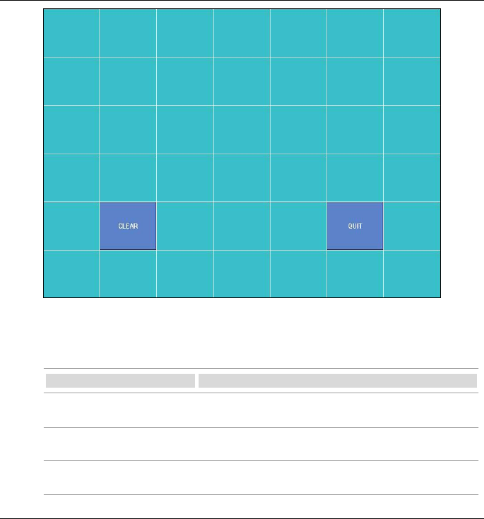
< Draw Test >
Test the drawing position related to the display screen on panel. There
will be a squared blue display showing. In drawing test windows, user
can click “Clear” button to clear the window.Also,click “Quit” button
to quit from the drawing test.
In drawing test windows, users can verify the panel linearity,
calibration capability, and drawing line quality.
49
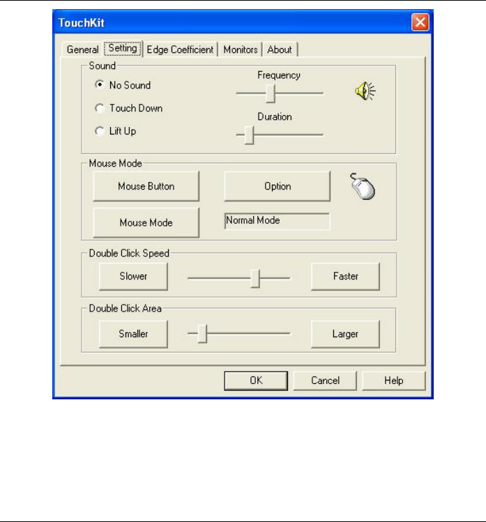
< Setting >
There are three function groups – “Sound Option”,”Mouse
Mode”,”Double click Adjustment” in this page.
Function Description
Sound Option Provide the click feedback while touching the
panel.
Mouse Mode Click it to show or hide TouchTray. Provide
option for advanced mouse emulation setting.
Double click Adjustment Provide user set up the tolerance while double
clicking.
50

51
Intentionally Left Blank
52
Troubleshooting

53
This chapter describes locating and solving problems that you may
encounter while using your computer.
General Hardware Problems/Possible Cause and Solution
A few common hardware problems and suggested solutions are
presented in the table below:
Antenna Problem/Solution
Problem Possible Cause Solution
The internal wireless
local area network
(LAN) is not functioning.
The antennas are
obstructed
Try to prevent the
antennas from being
obstructed and be sure
the computer access
point is quite near you.
Audio Problems/Solutions
Problem Possible Cause Solution
No sound can be heard. Either the volume is
muted or turned down.
Use the Microsoft
Windows volume
control icon at the lower
righthand corner of the
display to adjust the
volume.
No sound on the
external speakers or
headphones.
Connected to the wrong
jack.
Change to the correct
jack.
Battery Problems/Solutions
Problem Possible Cause Solution
Beeping sound. The computer battery is
low and Hibernation is
disabled.
Connect the computer
to an external power
source immediately.

54
The battery pack is
warm after charging.
This is a normal
condition.
No action is required.
No power is connected
to the computer.
Check the power
source.
The battery is fully
charged.
Refer to the battery icon
located at the lower
righthand corner of your
screen if you are
operating on battery.
Battery pack was
exposed to a high
temperature.
Let the battery pack
reach room temperature
before use.
The battery LED
indicator does not light
when the battery is
charging or if it is not
charging.
The battery pack is
nearing the end of its
life.
Replace the battery
pack.
Battery charge guage
not accurately
displaying the charge
remaining
Battery pack requires
calibration.
Calibrate the battery
pack.
Display Problem/Solution
Problem Possible Cause Solution
Rotation button is not
functioning.
A-Menu software is not
installed
Install A-Menu software
using the support CD
Driver.
Internet Problems/Solutions
Problem Possible Cause Solution
The computer is unable
to connect to the
Internet.
Account for Internet
service provider (ISP) is
not properly configured.
Ask for your ISP
assistance.

55
Network Problem/Solution
Problem Possible Cause Solution
The system does not
connect to the network
The settings are not
correctly set.
Contact your network
administrator.
Ordinary Pen Problems/Solutions
Problem Possible Cause Solution
The cursor is not
functioning properly
while using the ordinary
pen.
Device was missing. Executing the touchkit
program then add the
device COM1 again.
The cursor not in
position while using the
ordinary pen.
Computer settings not
calibrated.
Change the settings in
the touchkit settings
window. Select
TouchKit program>4
pts Cal to calibated.
Power Problems/Solutions
Problem Possible Cause Solution
The computer is
connected to an
external power source
but does not turn on
even though the battery
pack is connected.
The battery pack may
be defective.
Replace the battery
pack.
The Power/Standby
light is off and the
system turns off when it
is left unattended.
The system initiated
Hibernation mode
Press the Power button.
The system will not turn
on after it turns off
when left unattended.
The system initiated
Hibernation because it
is in critical low-battery
condition.
Connect the computer
to an external power
source.

56
Screen Problem/Solutions
Problem Possible Cause Solution
The screen is blank. Standby or Hibernate
has initiated.
Exit Standby or
Hibernate.
External monitor display
is selected
Switch to the computer.
(Refer to “Software
Utilities” searction of
Chapter 6.
USB Problem/Solutions
Problem Possible Cause Solution
The external device
does not work when
connected to the USB
connector.
The external device is
not receiving power.
Ensure that the external
device is plugged into
an electrical outlet.
The external device is
defective.
Try connecting the
external device to
another computer to
determine if it operates
properly.
Contacting Your Dealer
If you still have a problem after reading the preceding section, the next
step is to contact your dealer.
Your dealer can determine if the problem is something that requires the
computer to be taken to the shop. Before you call your dealer, however,
please have the following information available:
How is your computer configured? Your dealer needs to know what
peripheral devices you are using.
What messages, if any, are on the screen?

57
What software were you running at the time?
What have you done already to try to solve the problem? If you have
overlooked a step, your dealer may be able to solve the problem over
the phone.
58
How do I Expand my
Computer?
59
How to upgrade your RAM module
Refer to the following instructions and illustration for information on upgrading your computer’s
memory.
Turn off your computer and turn it over.
Locate the DDR-RAM module compartment in the center of the
bottom panel of the system. Unscrew the two screws that secure the
DDR-RAM module compartment cover.
60
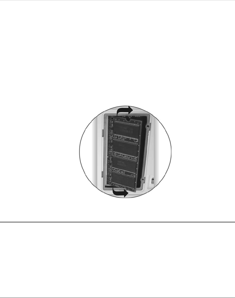
Remove the cover and set aside.
Locate the DDR-RAM modules.
Using your fingers or a small screwdriver, press the two plastic tabs
on the sides of the DDR-RAM module away from the modules.
The DDR-RAM module should pop out slightly.
Gently pull out the DDR-RAM module as shown on the illustration.
To replace the
DDR-RAM module,
align the DDR-
RAM module
connector with the
DDR-RAM module
socket and press the
DDR-RAM module
down until it clicks
into place.
Once the module is
properly seated, you
can replace the
cover on this
compartment.
1. Replace and tighten the screws.
Easy to Upgrade HDD Module

61
Your computer provides you with a HDD that is easy to upgrade. Before installing a new drive,
all the files in your system should be backed up.
62
How to upgrade your Hard Drive

63
Turn off your computer and turn it over, locate the battery
compartment to remove the battery from your system.
(Refer to the “Inserting and Removing the Battery Pack” section
in Chapter 3.)
After you have removed the battery from your system, set it aside.
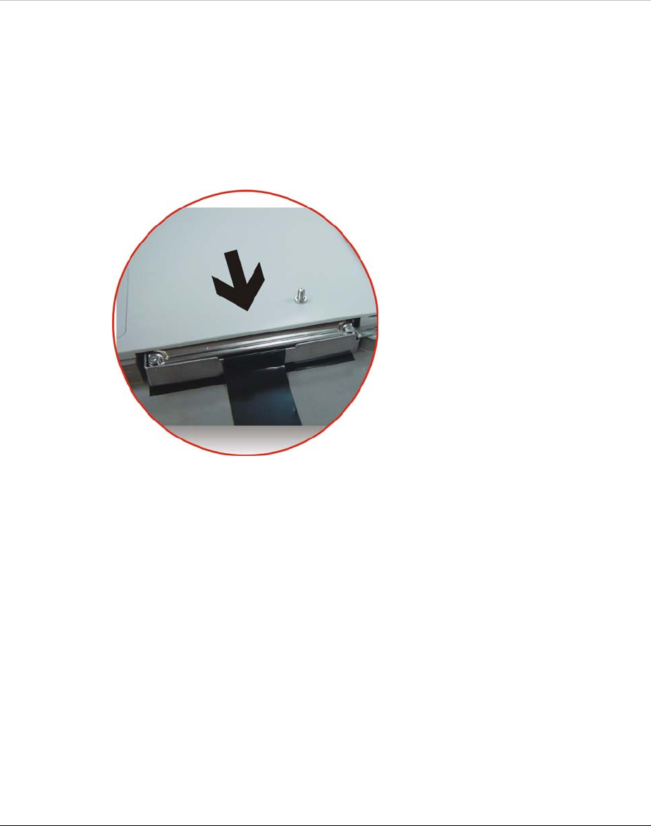
Locate the HDD compartment right beside the battery compartment.
Remove the screw that is secured with the HDD compartment.
Hold the HDD release strip away from its compartment as shown
on the illustration.
64
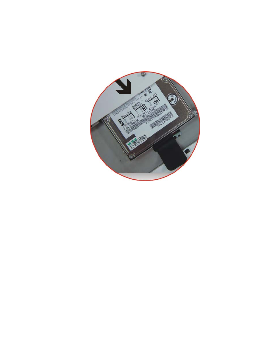
Replace the HDD
and insert it back
into the
compartment.
After the HDD is
securely inserted,
lock the
compartment with
the screw that you
have removed
earlier when you
are removing the
HDD.
Insert the battery
back into the
battery
compartment.

65
Intentionally Left Blank
66
Specifications

67
Detailed Specifications
Features Tablet PC
Processor • INTEL (Ultra) Low Voltage Mobile Pentium M
or Dothan 900MHz up to 1.3GHz
Core Logic Chipset • North Bridge: Intel GMCH-M 855GM(E)
• South Bridge: Intel ICH4-M
Cache • 1 MB L2 Cache (Pentium M) or 2 MB L2
Cache (Dothan)
System Memory • One DDR-SODIMM Support up to 1GB,User
upgradeable
BIOS ROM • 512KB flash with boot block or above
Graphics Controller • Integrated on Intel GMCH-M 855GM(E)
• Supports Dual Display Options
Audio • AC-97 Rev 2.3 Compliant
• Two 1W Speakers
Digitizer • Electromagnetic
• 133 samples/second
• Resolution: 2540 PPI
• Full Size Stylus Included
Communication • Ethernet
• Built In 10/100 Ethernet Port
Onboard Wireless • Built In Intel Calexico 802.11b/g or
802.11a/b/g Wireless LAN
• Trial mode Antenna

68
Mass Storage • 20/30/40/60GB HDD with support for larger
capacity
• 2.5”size, 9.5” height, 5V
• User Upgradeable
Modem • MDC software Modem 56Kbps V.90
External
Connectors
• DC-IN Jack
• D-Sub15 External Monitor Out
• CF card type I and type II with hot insertion
and removal
• RJ45/RJ11 Port
• IEEEE 1394 port
• USB 2.0 Type A x2
• Headphones Out
• Microphone In
• Docking Station Interface
User Controls • Power On/Off switch
• SAS key
• Menu key (Pop Up short cut Menu)
• WWW key
• Screen Rotation key
• Wireless On/Off Switch
• Up/Down/Enter key
User Indicators • Power On / Suspend indicator
• Battery State indicator
• HDD Access indicator

69
• RF On/Off indicator
Battery Pack • 3S2P Lithium Ion Smart Battery
(3.6AH@11.1V) 3.5 hours battery life,
Weight:338g
• Note: Battery life is tested by mobile
mark2002 at LCD 97 nits.
AC Power Adapter • 19VDC @ 60W LI SHIN:LSE0208A1960,
DC19V, 3.16A
• Worldwide EMI and Safety Approvals
Operating System • Microsoft Windows XP Tablet PC Edition
Touch Panel • WinXP Home Edition/Professional
Optional Accessory • External Charger
.