Amtran Technology Co AZW9271-240 IEEE 802.11 b/g/n USB wireless module User Manual
Amtran Technology Co Ltd IEEE 802.11 b/g/n USB wireless module
user manual
1 -
AW-NU240
IEEE 802.11b/g/n
USB Wireless Module
AMTRAN: CUS233
User’s Manual
2 -
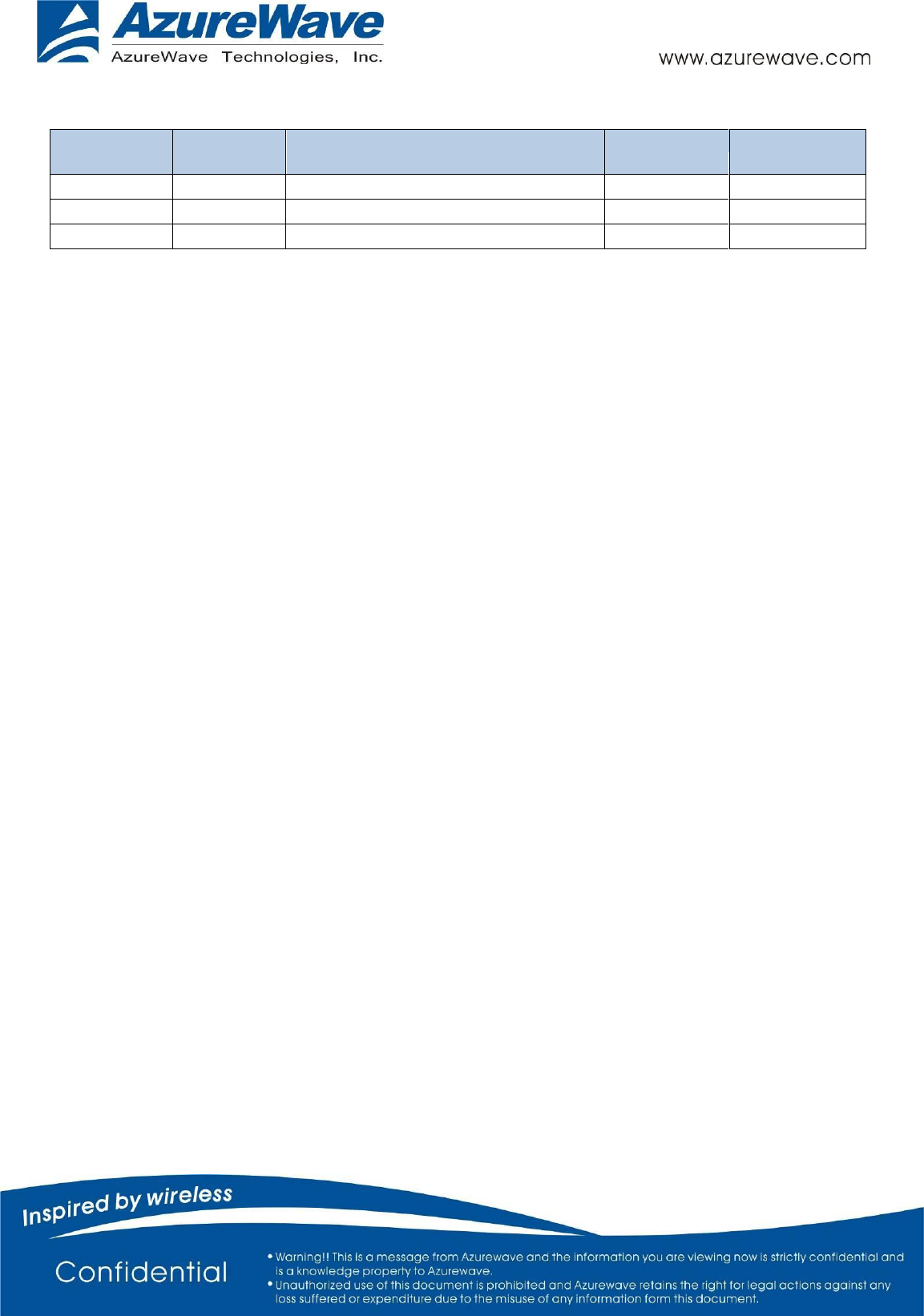
Document
release
Date
Modification
initials
Approved
Version 0.1
2012/07/27
Initial release
Johnny Wei
Antonio Chu
Version 0.2
2012/09/18
Update general spec
Johnny Wei
Antonio Chu
Version 0.3
2012/09/28
Update note/label
Amber Tseng
Ray Lee

3 -
1. Introduction
AzureWave Technologies, Inc. introduces IEEE 802.11b/g/n USB wireless module, AW-NU240. This
USB wireless module is a highly integrated wireless local area network (WLAN) solution to let users enjoy
the digital content through the latest wireless technology without using the extra cables and cords. It
enables a high performance, cost effective, low power, compact solution that easily fits onto one side of a
USB.
Compliant with the IEEE 802.11b/g/n standard, the AW-NU240 uses Direct Sequence Spread Spectrum
(DSSS), Orthogonal Frequency Division Multiplexing (OFDM), BPSK, QPSK, CCK and QAM baseband
modulation technologies. A high level of integration and full implementation of the power management
functions specified in the IEEE 802.11 standard minimize system power requirements by using
AW-NU240.
Longer Range and Faster Speed
Comparing to 802.11g technology, 802.11n standard make big improvement on speed and range. It
Increases wireless range by up to 2 times and reduces dead spots in coverage area. The robust signal
travels farther, maintaining wireless connections more farther than standard 802.11g. The data rate can
up to 150Mbps data rate.
2. Features
USB module
Compliant with IEEE802.11n standard
Antenna to support 1(Transmit)* 1 (Receive) technology
High speed wireless connection up to 150Mbps
Low power consumption and high performance
Enhanced wireless security
4 -
3. General Specifications
Model Name
AW-NU240
Product Description
IEEE 802.11 b/g/n USB wireless module
WLAN Standard
IEEE 802.11b/g/n, Wi-Fi compliant
Host Interface
USB
Major Chipset
Atheros AR9271L ( MAC/Baseband/RF ) Single chip
Dimension
50 x 17 x 9.6 mm
Weight
8 g
Antenna
Metal Antenna on PCB
1. Main: TX/RX
USB Connector
JS-1125R-05
RF Connector
Murata MM8430-2610
Operating Conditions
Voltage
3.3V +/- 5%
Temperature
0~80oC
Cold start
Turn on after storage at 0 oC for 6hrs
Long time connection
Keep operating at 60 oC after 168hrs
Electrical Specifications
Frequency Range
2.4 GHz ISM Bands 2.412-2.472 GHz, 2.484 GHz /
Modulation
802.11 g/n: OFDM
802.11b: CCK(11, 5.5Mbps), QPSK(2Mbps), BPSK(1Mbps)
Receive Sensitivity
802.11b: 11M less then -76dBm (High data rate)
802.11g: 54M less then -65dBm (High data rate)
802.11n: HT20 MCS7 less then -64dBm (High data rate)
HT40 MCS7 less then -61dBm (High data rate)
Operating Range
Open Space: 300M
(The transmission speed may vary according to the
environment)
Operating
System Compatibility
Windows Linux
Regulatory (EMI)
FCC ( For USA)
Part De-rating test
Follows the current spec of each component
5 -
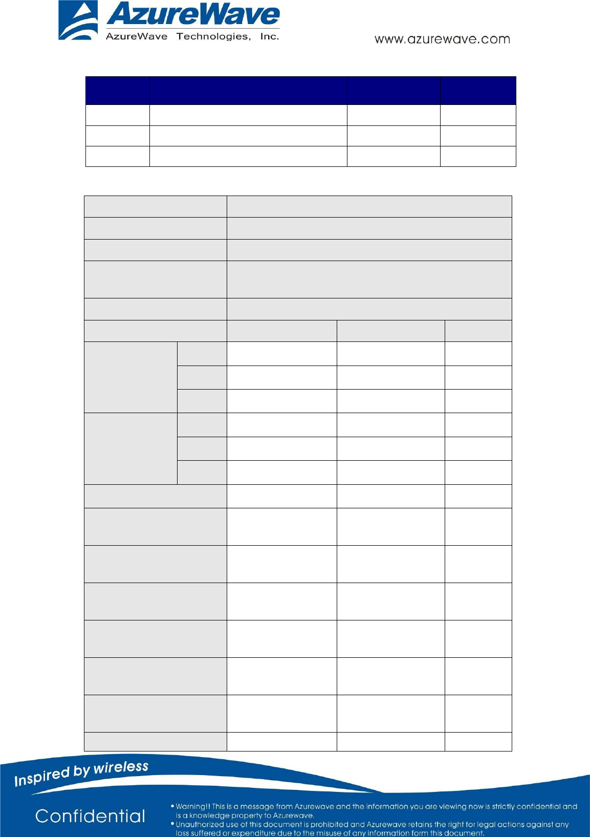
4-1. Absolute Maximum Ratings
Symbol
Parameter
Max. Rating
Unit
Vdd3.3V
Maximum I/O supply voltage
–0.3 to 3.465
V
RFin
Maximum RF input (reference to 50 Ω)
+10
dBm
Tstore
Storage temperature
–20 to 85
°C
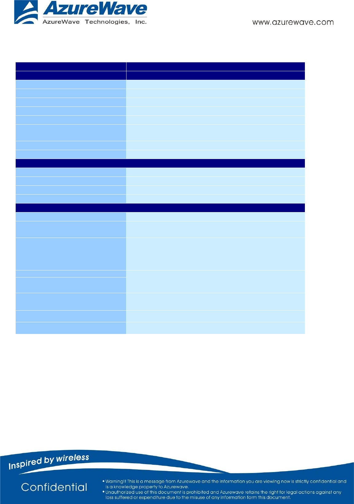
4-2. Power Consumption
Test Bed
DELL VOSTRO 3450
Test OS
Windows 7 Ultimate x64 SP1
Test AP
D-LINK DIR-855
Driver Version
AZ_AR9271_XP_7.7.0.98_VT_8.0.0.80_WIN7_2.0.0.5
7_20101105
Test Voltage
3.3V
Item
L0 Mode
L1 Mode
NOTE
WLAN Module
No Connect AP
AVG
44.4 mA
N/A
MAX
212.0 mA
N/A
MIN
39.8 mA
N/A
WLAN Module
Connect to the
AP
AVG
209.2 mA
N/A
MAX
250.1 mA
N/A
MIN
105.4 mA
N/A
WLAN
RF
OFF
N/A
N/A
Transmit Packet Test
11Mbps*
328.1 mA
N/A
Receiver Packet Test
11Mbps*
192.0 mA
N/A
Transmit Packet Test
54Mbps*
271.5 mA
N/A
Receiver Packet Test
54Mbps*
190.6 mA
N/A
Transmit Packet Test HT
20*
334.7 mA
N/A
Receiver Packet Test HT
20*
193.5 mA
N/A
Transmit Packet Test HT
358.0 mA
N/A
6 -
40*
Receiver Packet Test HT
40*
239.6 mA
N/A
Note. 1. The power consumption data were measured when NB operated in DC
(battery) mode.
2. Device not support L1 mode.
7 -
5. Connector Pin-out Definitions
Pin No.
Definition
Basic Description
Type
1
GND
Ground.
GND
2
USB_D+
USB Differential signal.
Digital
3
USB_D-
USB Differential signal.
Digital
4
Power
3.3V power supply.
Vcc
5
Reset_B
Reset if low.
Input
8 -
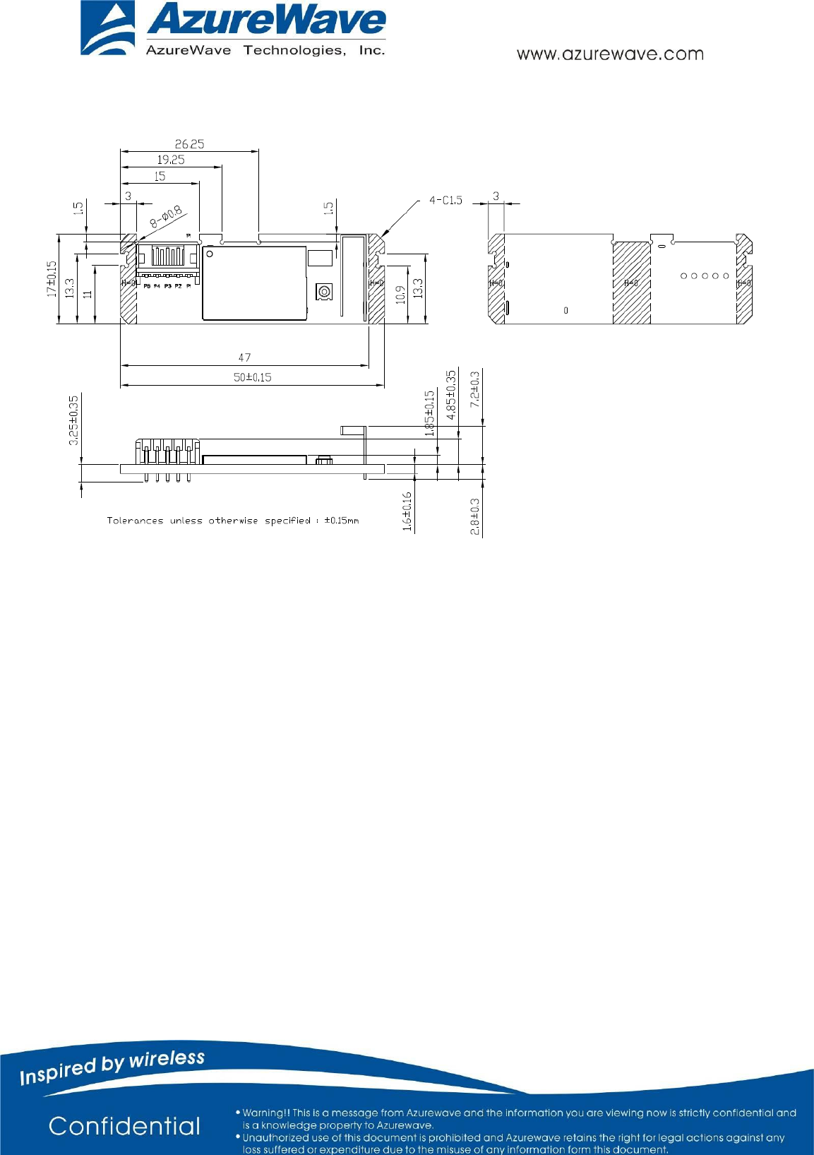
6. Mechanical drawing

9 -
FCC Statement:
Federal Communication Commission Interference Statement
This equipment has been tested and found to comply with the limits for a Class
B digital device, pursuant to Part 15 of the FCC Rules. These limits are
designed to provide reasonable protection against harmful interference in a
residential installation. This equipment generates, uses and can radiate radio
frequency energy and, if not installed and used in accordance with the
instructions, may cause harmful interference to radio communications.
However, there is no guarantee that interference will not occur in a particular
installation. If this equipment does cause harmful interference to radio or
television reception, which can be determined by turning the equipment off and
on, the user is encouraged to try to correct the interference by one of the
following measures:
● Reorient or relocate the receiving antenna.
● Increase the separation between the equipment and receiver.
● Connect the equipment into an outlet on a circuit different from that to which
the receiver is connected.
● Consult the dealer or an experienced radio/TV technician for help.
FCC Caution: Any changes or modifications not expressly approved by the
party
responsible for compliance could void the user’s authority to operate this
equipment.
This device complies with Part 15 of the FCC Rules. Operation is subject to the
following two conditions: (1) This device may not cause harmful interference,
and (2) this device must accept any interference received, including
interference that may cause undesired operation.
For product available in the USA/Canada market, only channel 1~11 can be
operated. Selection of other channels is not possible.
10 -
This device and its antenna(s) must not be co-located or operation in
conjunction with any other antenna or transmitter.
IMPORTANT NOTE:
FCC Radiation Exposure Statement:
This equipment complies with FCC radiation exposure limits set forth for an
uncontrolled environment. This equipment should be installed and operated
with minimum distance 20cm between the radiator & your body.
IMPORTANT NOTE:
This module is intended for OEM integrator. The OEM integrator is still responsible
for the FCC compliance requirement of the end product, which integrates this
module.
20cm minimum distance has to be able to be maintained between the antenna and
the users for the host this module is integrated into. Under such configuration, the
FCC radiation exposure limits set forth for an population/uncontrolled
environment can be satisfied.
Any changes or modifications not expressly approved by the manufacturer could
void the user's authority to operate this equipment.
USERS MANUAL OF THE END PRODUCT:
In the users manual of the end product, the end user has to be informed to keep at
least 20cm separation with the antenna while this end product is installed and
operated. The end user has to be informed that the FCC radio-frequency exposure
guidelines for an uncontrolled environment can be satisfied. The end user has to
also be informed that any changes or modifications not expressly approved by the
manufacturer could void the user's authority to operate this equipment. If the size
of the end product is smaller than 8x10cm, then additional FCC part 15.19
statement is required to be available in the users manual: This device complies
with Part 15 of FCC rules. Operation is subject to the following two conditions: (1)
this device may not cause harmful interference and (2) this device must accept any
interference received, including interference that may cause undesired operation.
11 -
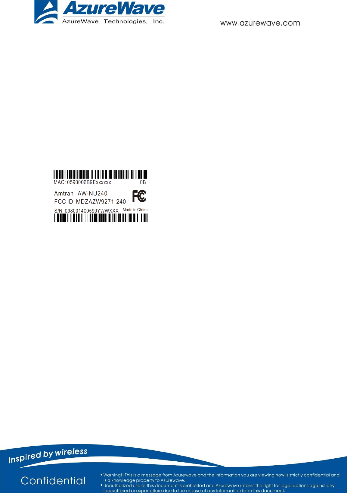
LABEL OF THE END PRODUCT:
The final end product must be labeled in a visible area with the following "
Contains TX FCC ID: MDZAZW9271-240 ". If the size of the end product is larger
than 8x10cm, then the following FCC part 15.19 statement has to also be available
on the label: This device complies with Part 15 of FCC rules. Operation is subject
to the following two conditions: (1) this device may not cause harmful interference
and (2) this device must accept any interference received, including interference
that may cause undesired operation.