Anbash Technology NC335SPW Network Camera User Manual
Shenzhen Anbash Technology Co., Ltd. Network Camera
UserManual.wiki
>
Anbash Technology
>
NC335SPW User Manual
User manual
Navigation menu
Upload a User Manual
Namespaces
Wiki Guide
HTML
PDF
Info
Views
User Manual
Discussion / Help
Navigation
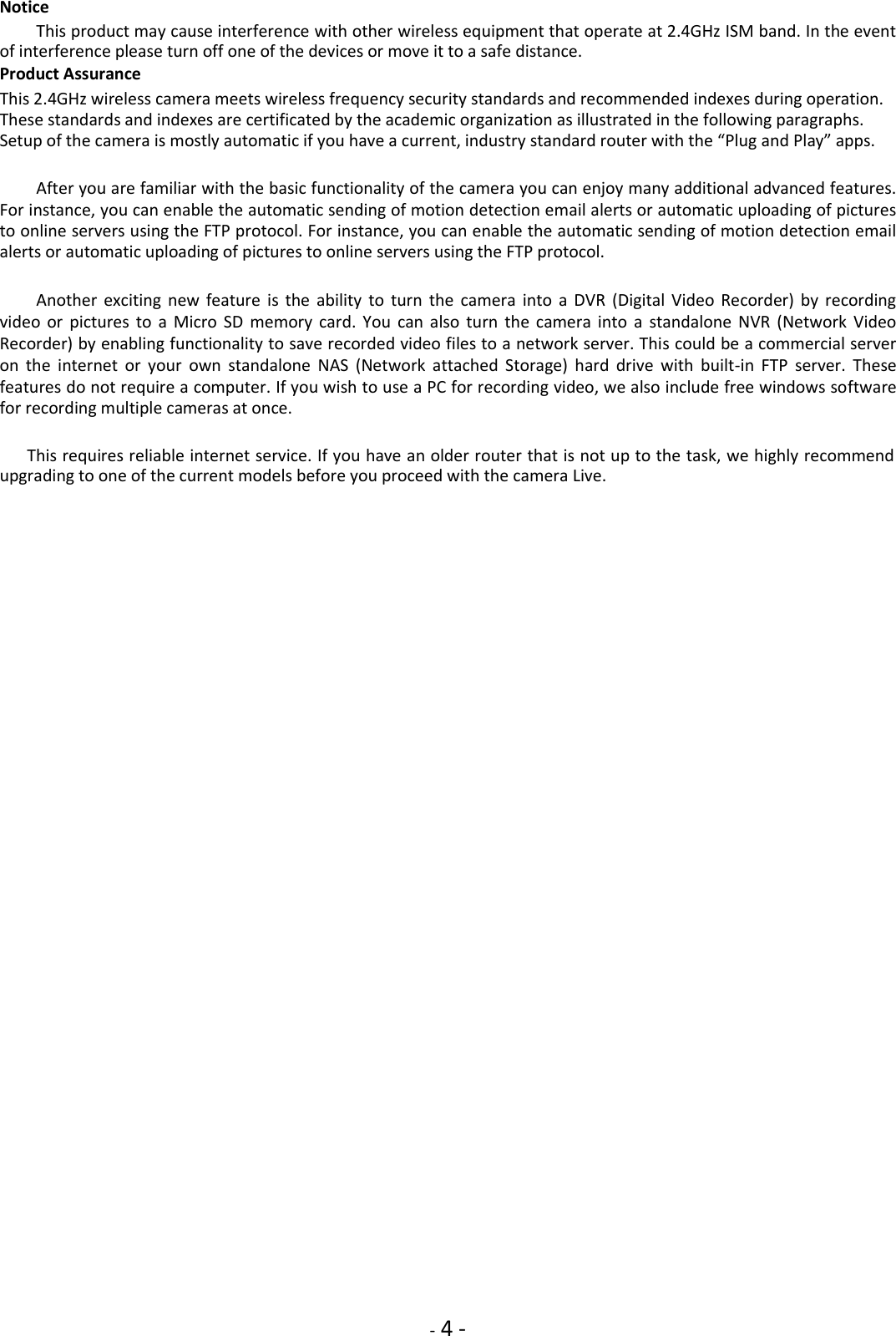
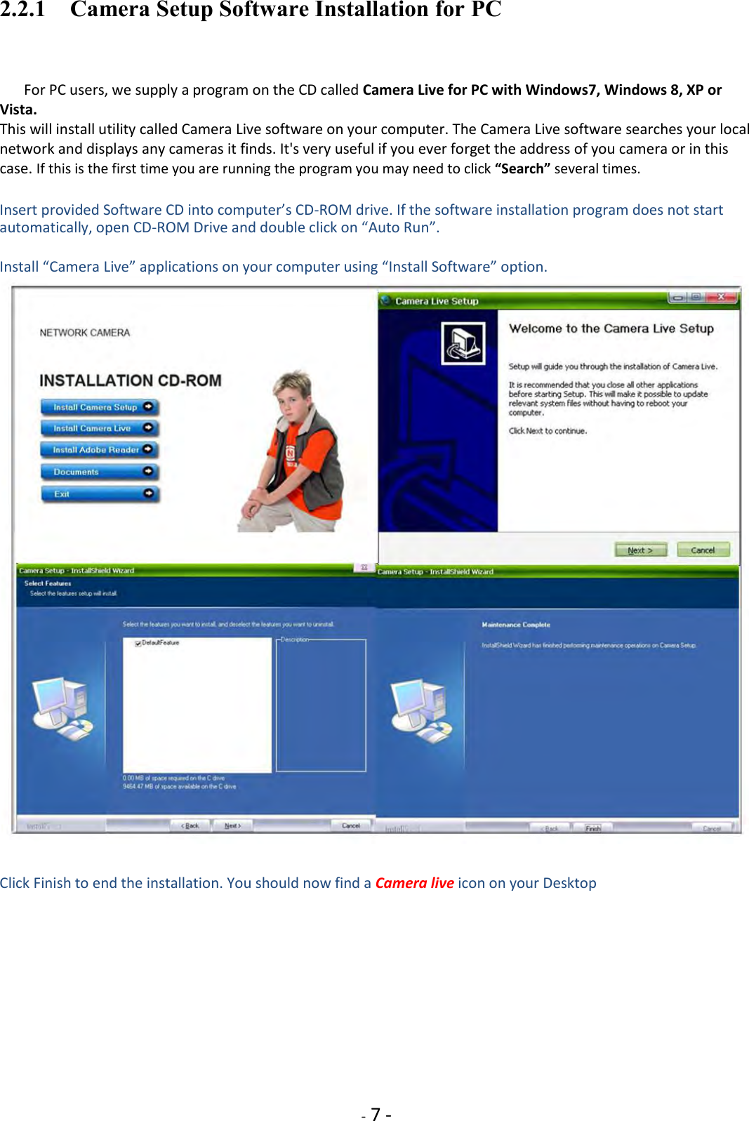
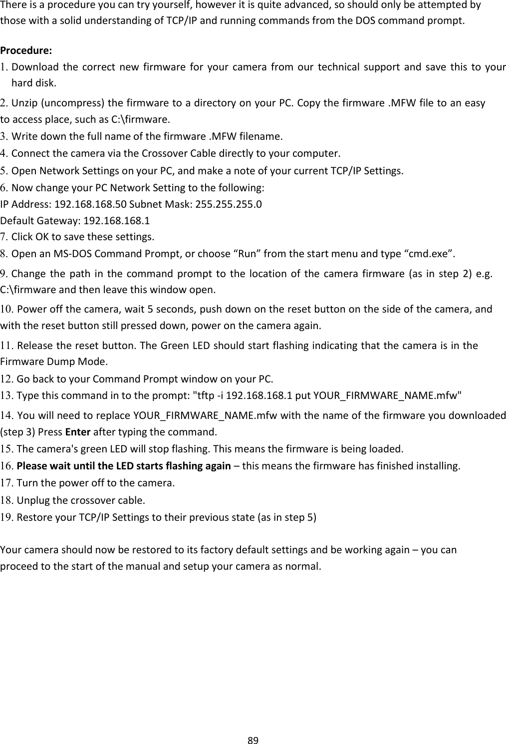
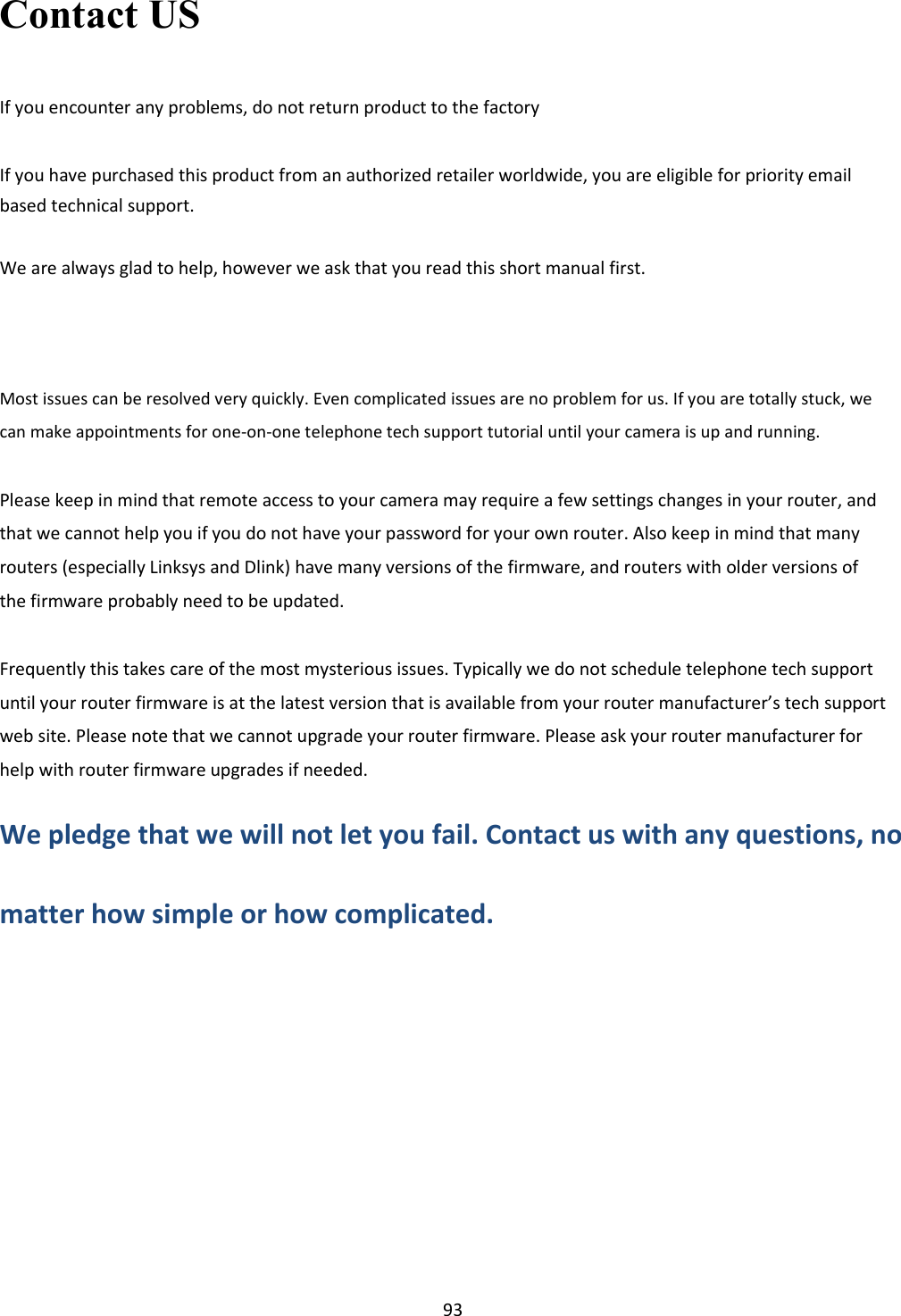
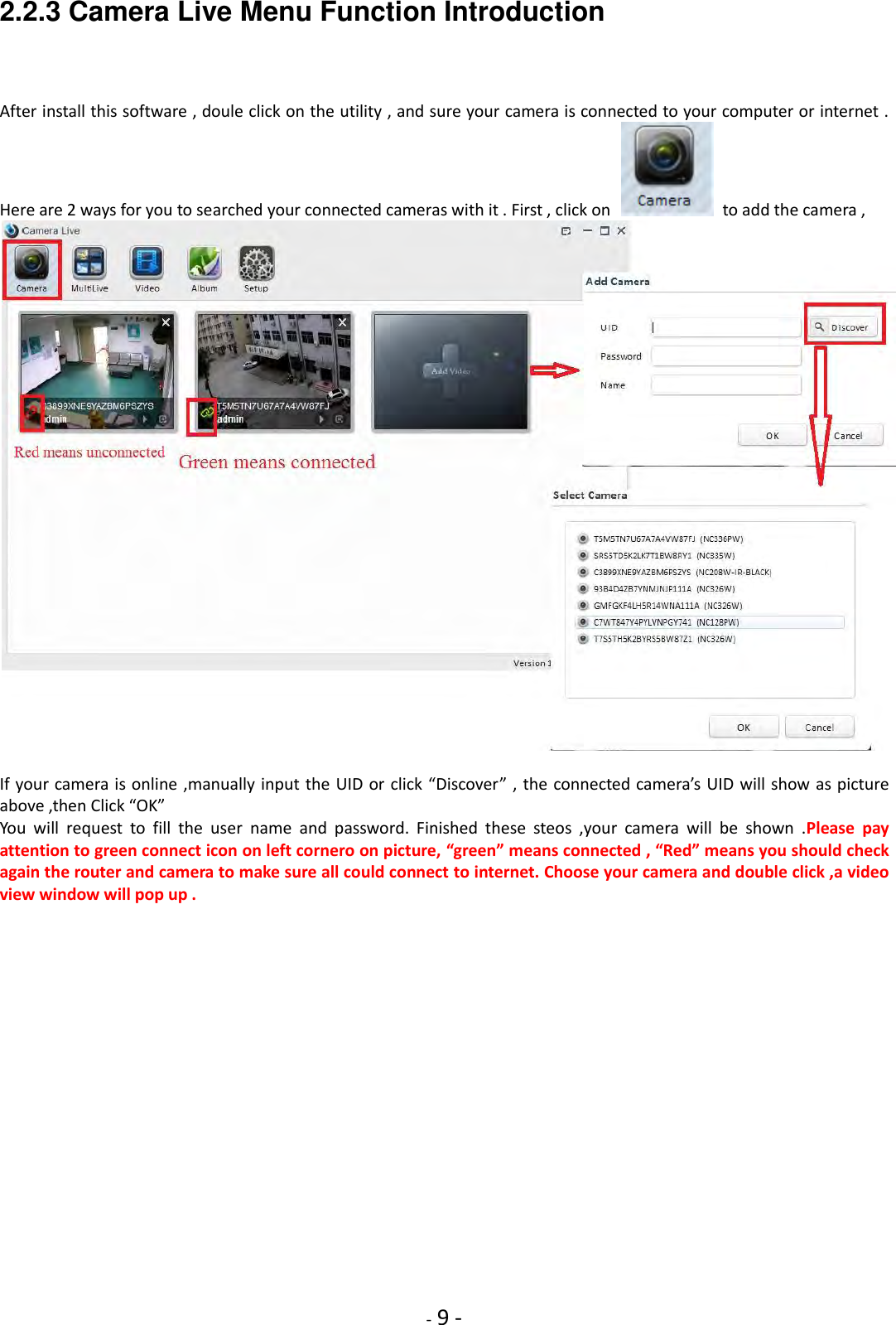
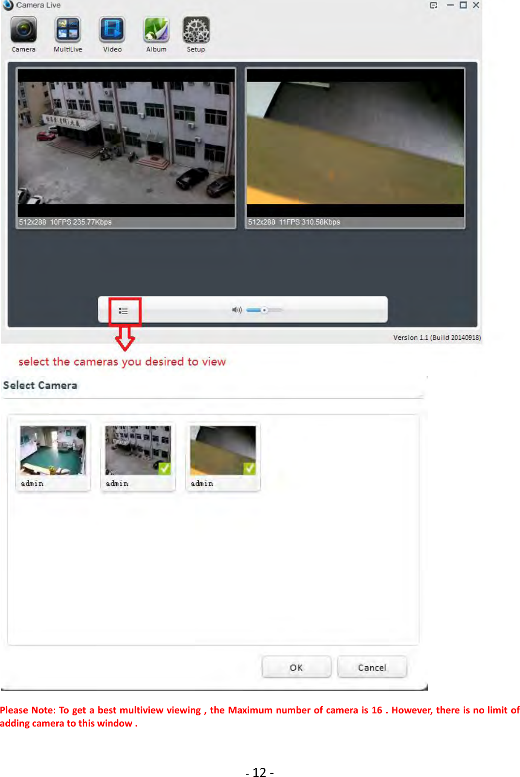
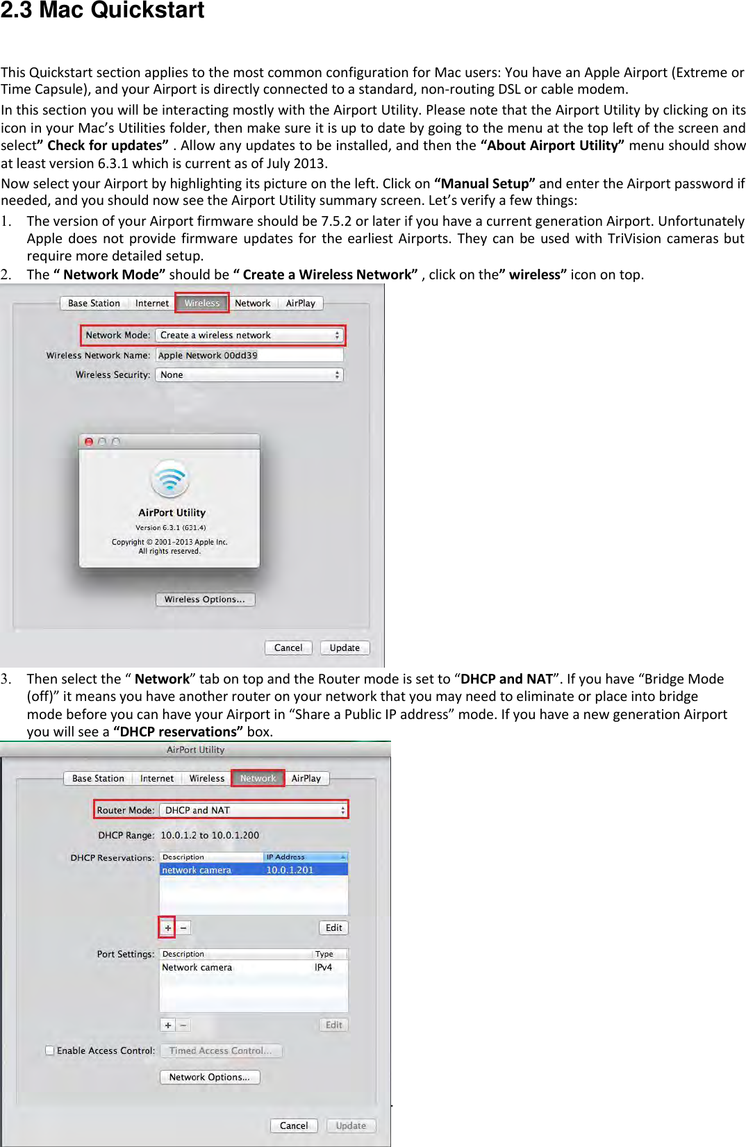
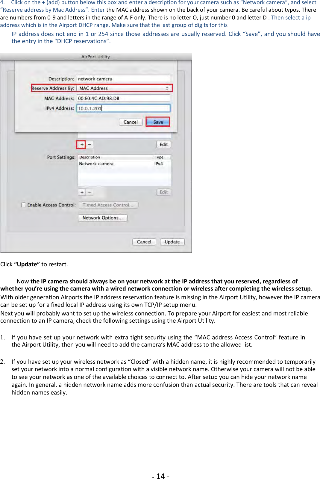
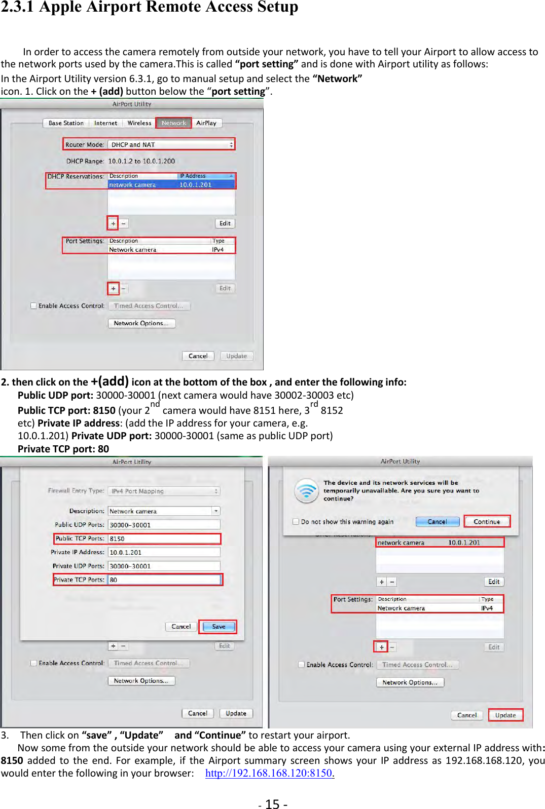
![- 8 - 2.2.2 Finding your Camera with Camera Live Utility Now you have your camera attached and the software ready, you are ready to find your camera on your network. Double-click the Camera Live icon on your Desktop to launch the Camera Live program. The Camera Live utility should automatically find your camera if it is correctly connected (See image below).You can use this program to set up cameras but we recommend that you use this program only to find your IP address. Then do all setup by going directly to the camera using the IP address, either by double-clicking on the address or by typing the number into your browser(with http:// in front) If no camera is found it could be that your Antivirus or Firewall program is blocking the “Camera Live” program. In that case you should either disable your Firewall program or use the alternate method of finding the IP address by checking the menus in your router as described below. Sometimes the program may take a few minutes to find your camera, so if your camera isn’t displayed, wait a few moments and then click “Search” to search for cameras again. [Search] – Searches your local network for cameras. [Browser] - Select the required camera and click Browser to access the camera via a web browser. [Clean] - Click clean to clean up the searched cameras . [Setup] - Select the required camera and click Setup to configure the network settings for the camera. Anytime you lose the IP address of your camera, you can run the Setup software to easily find it again. Once your camera is displayed, either chose “Search” to find the camera. Please note: The camera setup will only detect cameras that are on the same network as your computer. Ensure the camera is plugged into the same router/network switch that your computer is connected to](https://usermanual.wiki/Anbash-Technology/NC335SPW/User-Guide-3167460-Page-8.png)
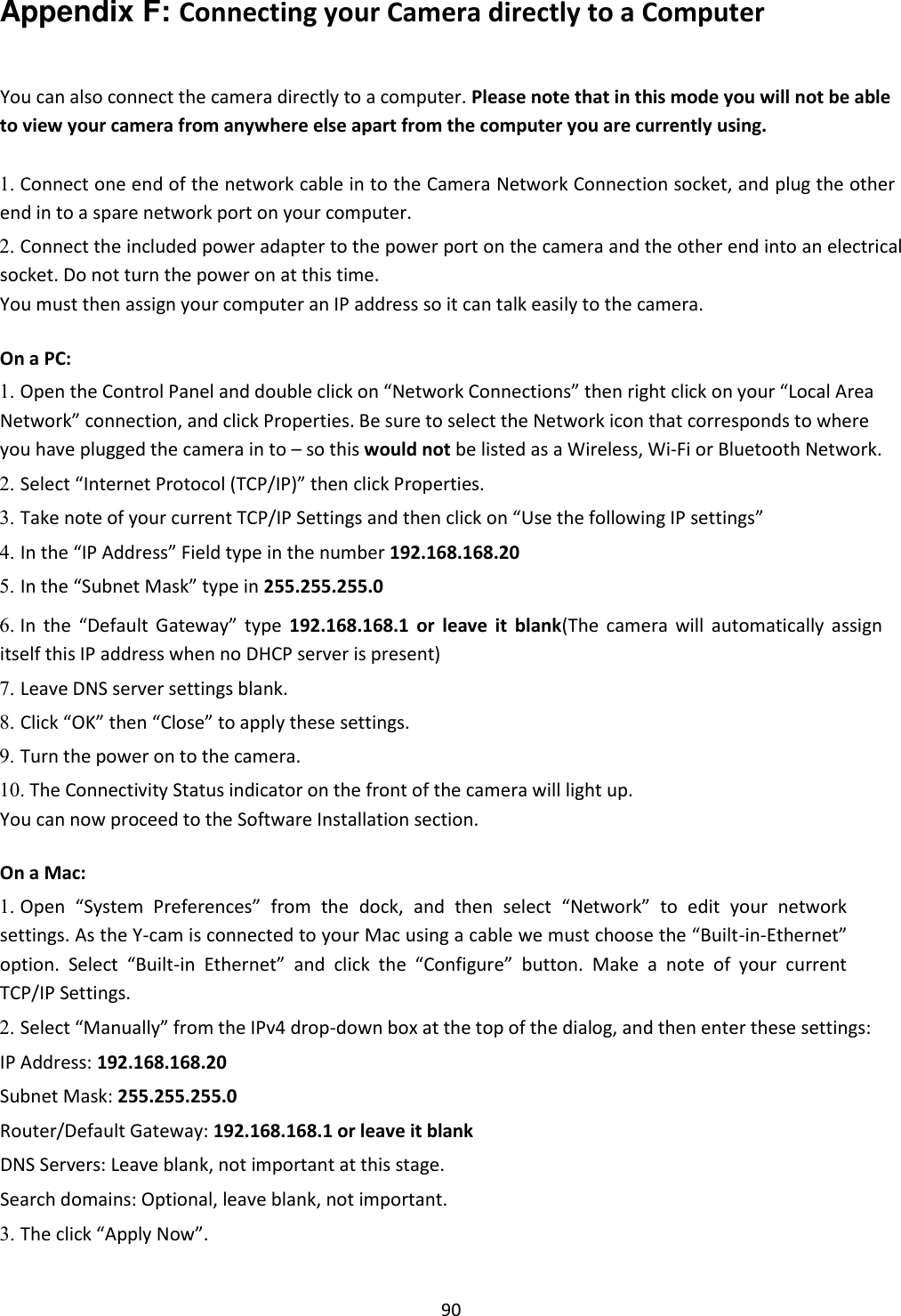
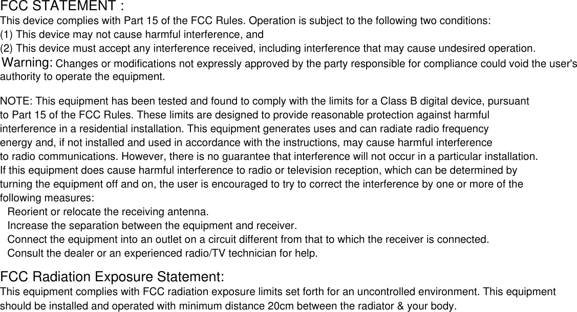
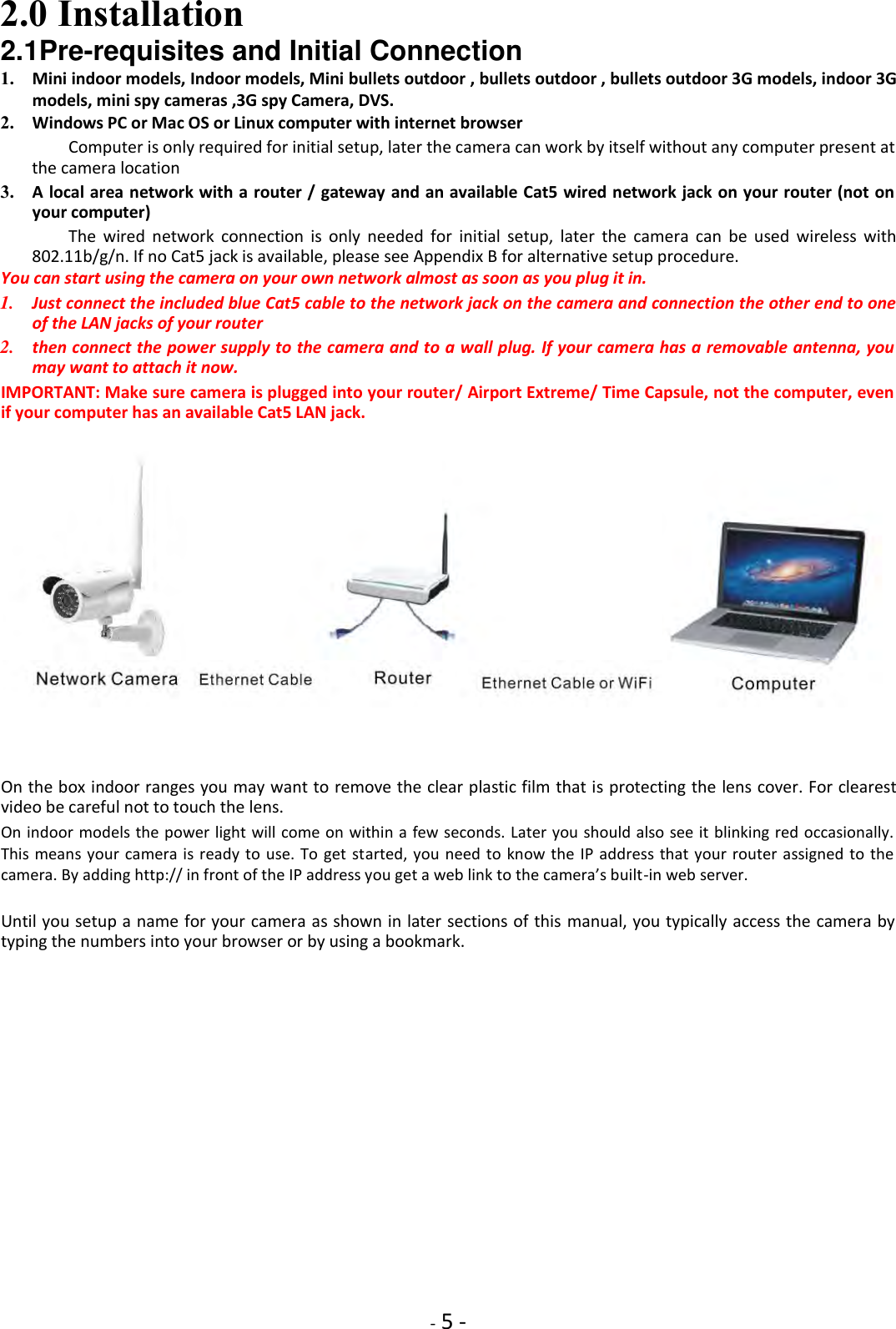
![- 16 - 2.4 Camera Homepage Regardless of the method you used to find your camera’s IP address, Once you have used the Camera Live Software to find your camera and opened your selected camera or entered the IP address manually into your browser” (with http:// in front) , you will be greeted with the Homepage for your camera (which should look something like the below screenshot depending on your model): [Enter] Lets you view live video transmitted by the camera. [Setting] This section allows you to setup your camera with its various settings. To see video, click on “Enter”, The default setting: Username: admin Password: admin. This is login is case sensitive, so should be entered exactly as they are above. It is recommended you change your password as soon as you are logged in - to avoid unauthorized access to the camera. Make a note of the password somewhere safe, as the only way to reset the password is to reset the cameras, so all settings will be lost. Please note: The password can be any mixture of lower and uppercase alpha-numeric characters. Extended characters are not permitted](https://usermanual.wiki/Anbash-Technology/NC335SPW/User-Guide-3167460-Page-16.png)
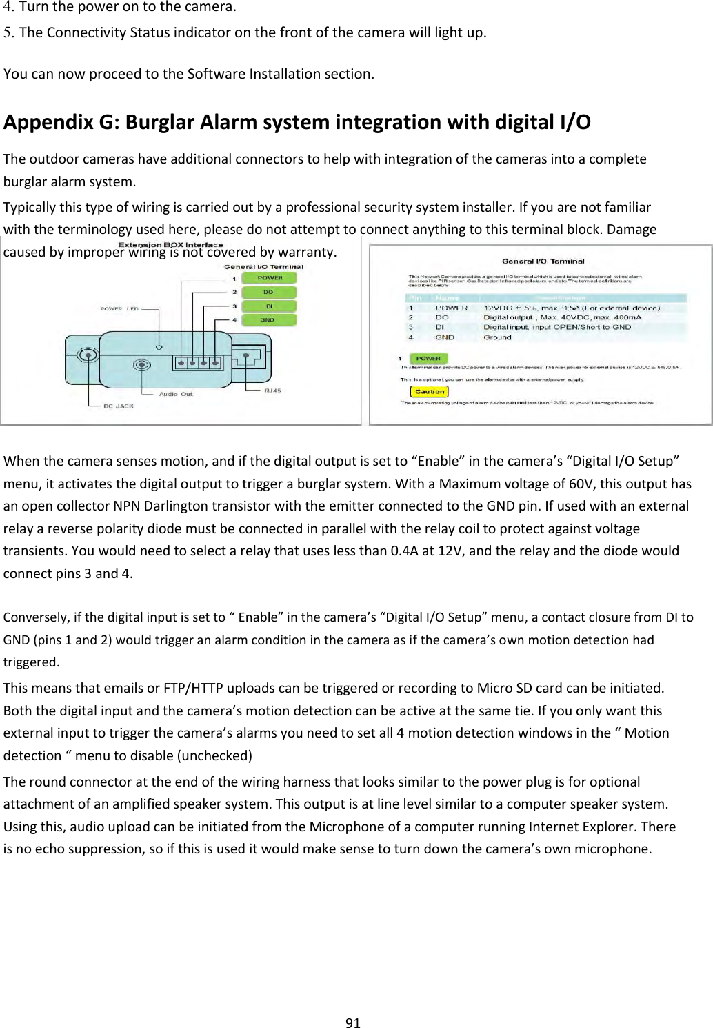
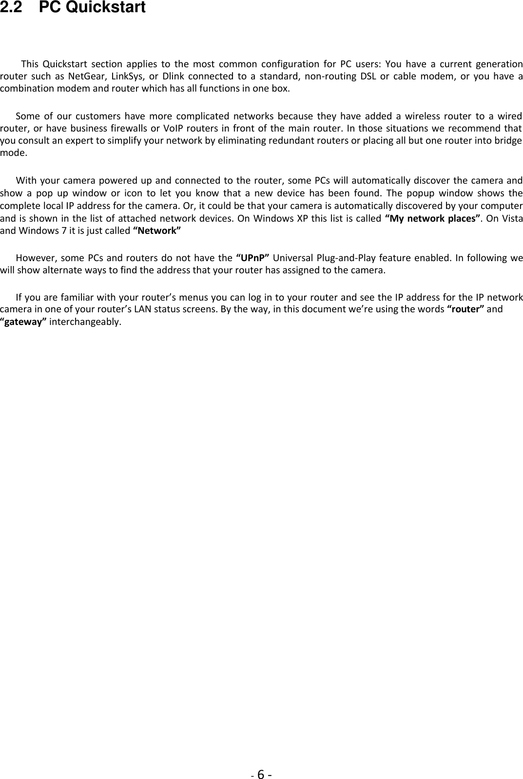
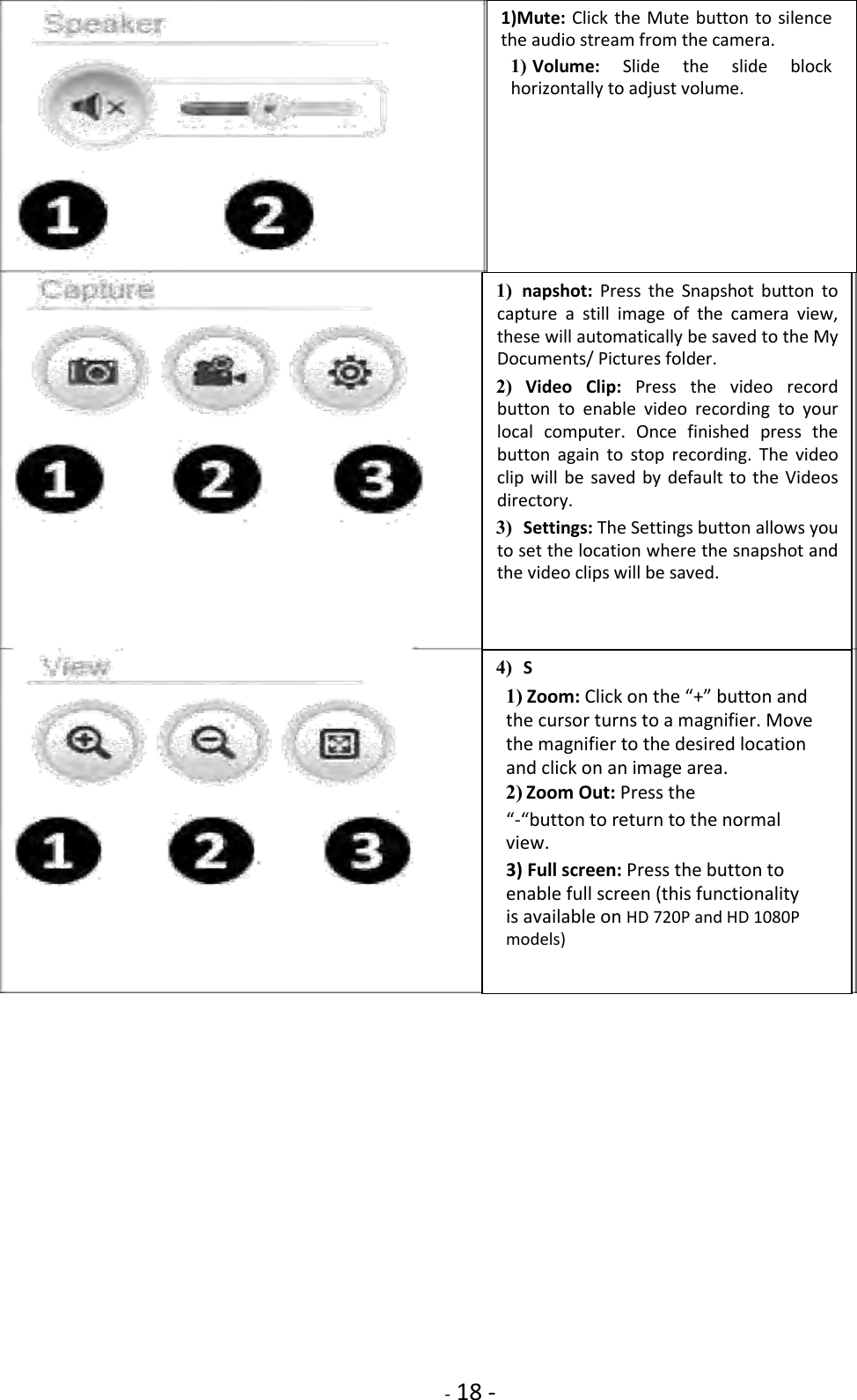
![- 17 - 2.5 Live View (using Internet Explorer) When using the camera for the first time on a PC with Internet Explorer, your PC will ask you for permission to install the viewing software (called ActiveX). This ActiveX is needed to decode the H.264 or MPEG4 video stream and control the camera. Click to “OK” this at the top of your screen, then again click on “OK” on the install menu that will pop up in the middle of your screen. If you have a popup blocker like Google Toolbar you will need to disable it. Within a few seconds you can then see live video from the camera. NOTE: If the camera shows video but also displays the message “connecting, waiting…”, close Internet Explorer and wait a couple of minutes for the camera to obtain current time from a internet time server and restart itself. The two links at the top of the screen are Home and Settings. [Home] This takes you back to your Camera Homepage. [Settings] This will take you to the cameras internal settings. Please view the next page for an explanation of the Operating Bar settings.](https://usermanual.wiki/Anbash-Technology/NC335SPW/User-Guide-3167460-Page-17.png)
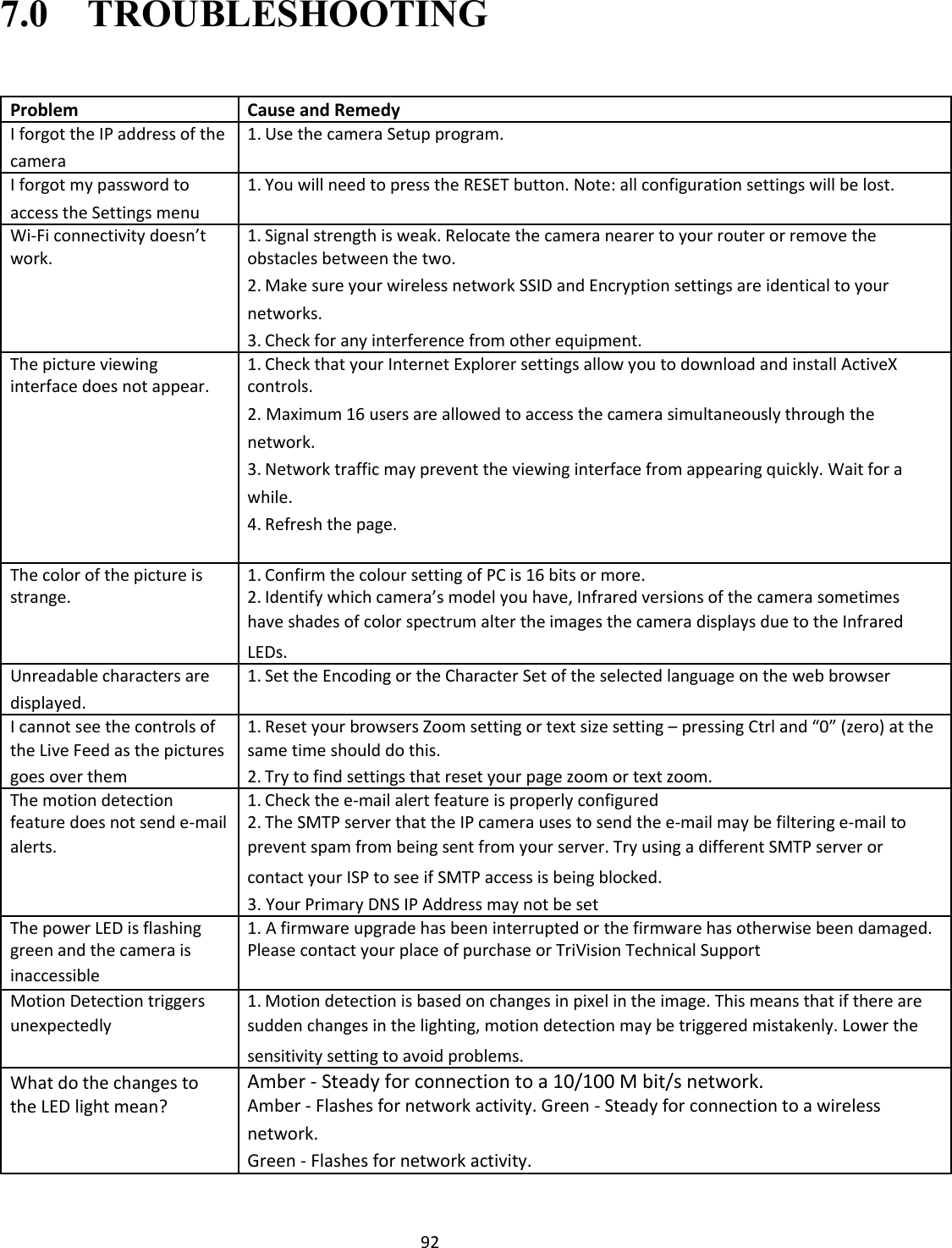
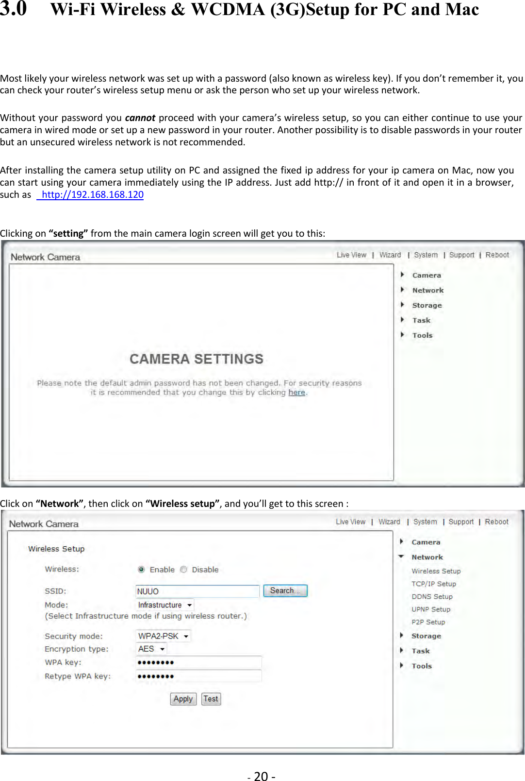
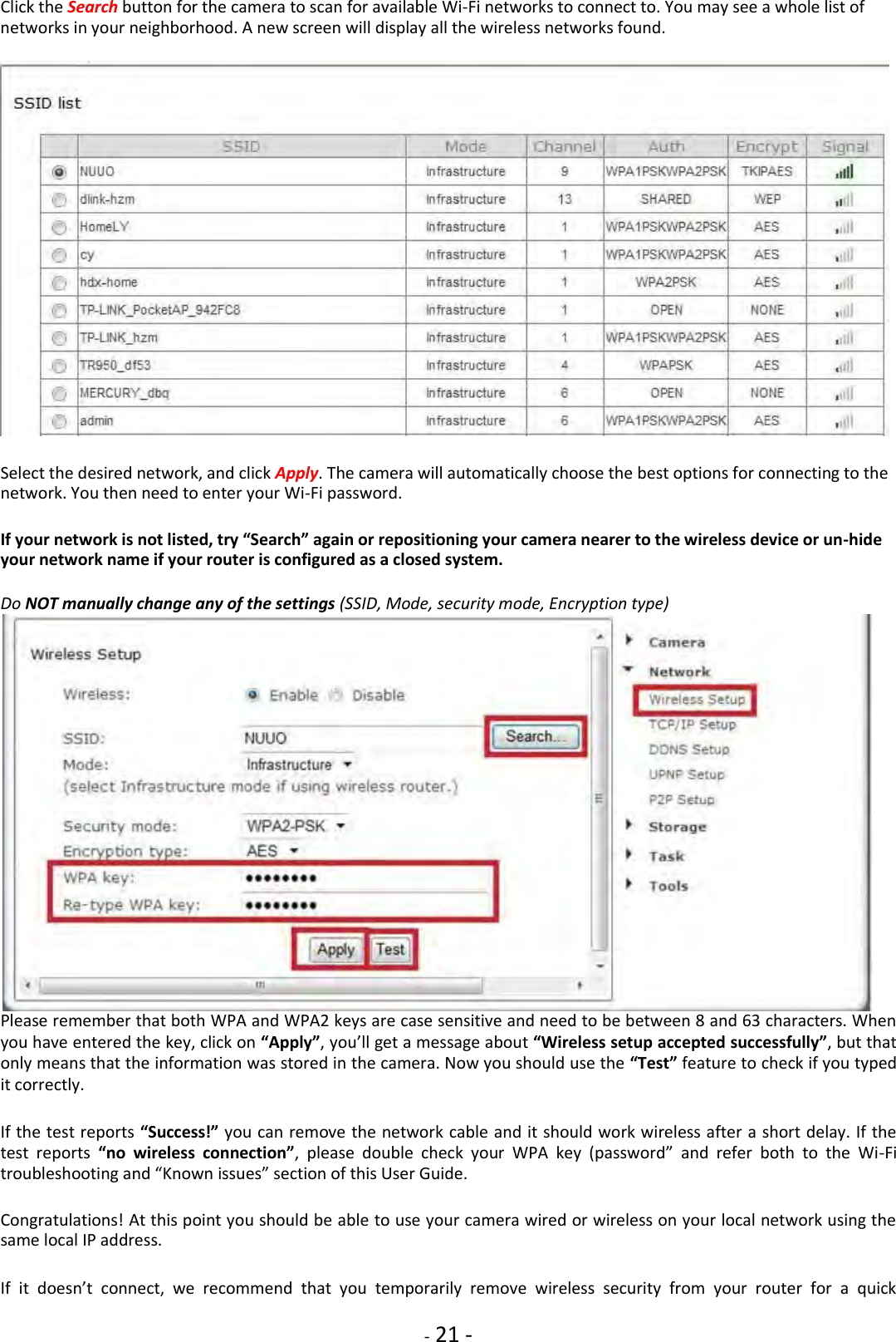
![- 19 - 2.6 Live View (using Firefox, Safari) Upon verification of the username and password, the camera image will begin to load. Adobe Flash Player or QuickTime or your media program may ask you to re-enter your login username and password at this point. This is common on most systems. Please note: You need to have QuickTime Pro Installed on your system to record videos directly from the web browser if you are using a program other than Internet Explorer. The links at the top of the screen are Home, Settings, Secondary Stream and Motion JPEG. [Home] This takes you back to your Camera Homepage. [Settings] will take you to the cameras internal settings. [Secondary Stream] This is set via your settings, and is useful if you need a lower resolution stream for certain devices (e.g. some mobiles and software) [Motion JPEG] This is a continuous motion JPEG stream – without any audio.](https://usermanual.wiki/Anbash-Technology/NC335SPW/User-Guide-3167460-Page-19.png)
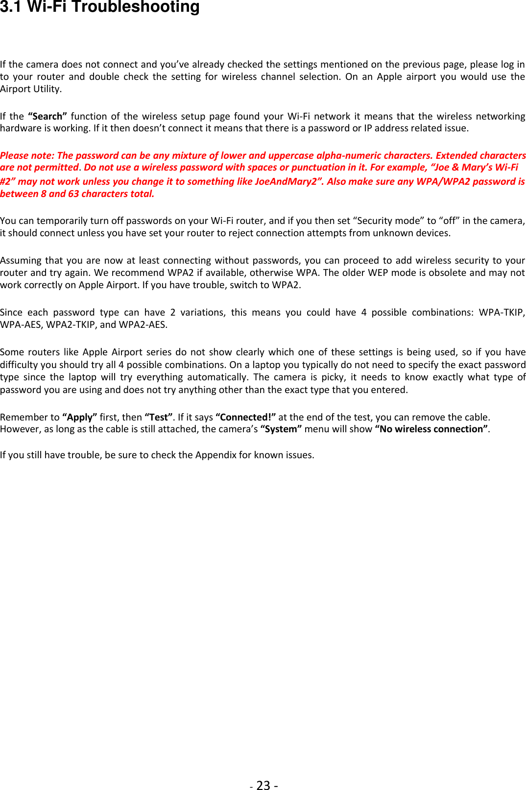
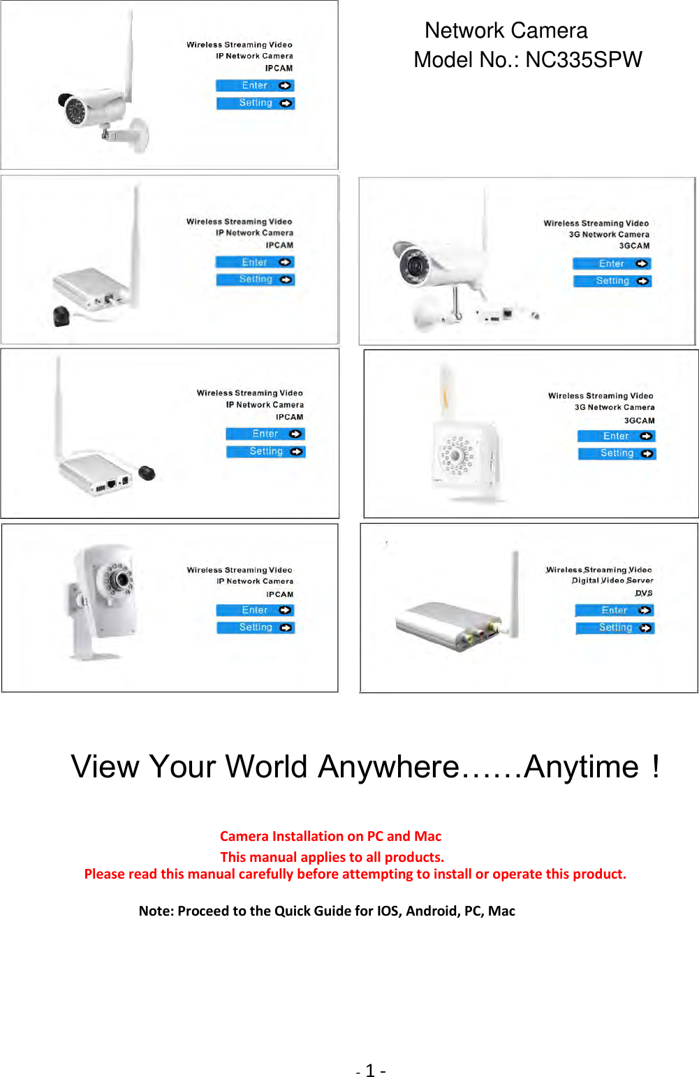
![- 27 - 4.2 UPNP SETUP---Enabling UPnP for Automatic Remote Access Setup Usually it is very simple to enable UPnP. You just need to log in to your router’s setup screen and find the UPnP menu. Then you click on enable, save the setting and restart both the router and the camera (in that order). The camera comes from the factory with the UPnP enabled. You can double check by selecting the UPnP Setup tab under the camera’s Network menu: [UPnP] Enable or disable the UPnP function. We recommend you to have UPnP enabled. For most users, the rest of the settings can be left as the default settings. [Gateway HTTP/RTSP port forwarding] If this is enabled, the camera will automatically add a port forwarding rule to your router via UPnP protocol. [External HTTP/RTSP port range] By default, this port range is 8150 – 8350. The ports are assigned in order, so if you only have one camera attached to your system, the chosen port will be 8150(8150-8150) for the first camera, 8151 for the second(8151---8151), and so on. Every camera will remember its port, and it will automatically use this port (if still available) whenever it is powered on. [Gateway RTP port forwarding] Used when viewing the feed through a VLC player. If not wishing to view the feed through a VLC this should be left enabled. [External RTP port range] The RTP port range can't be changed here - you should change it from the TCP/IP setup page. Click Apply to confirm your setting. If your router UPnP is enabled, the UPnP is still not shown as above, then power off the router and restart both the router and camera. If UPnP works, clicking on the camera’s “system” menu at the top of the setting screen will show something like the following in the UPnP section:](https://usermanual.wiki/Anbash-Technology/NC335SPW/User-Guide-3167460-Page-25.png)
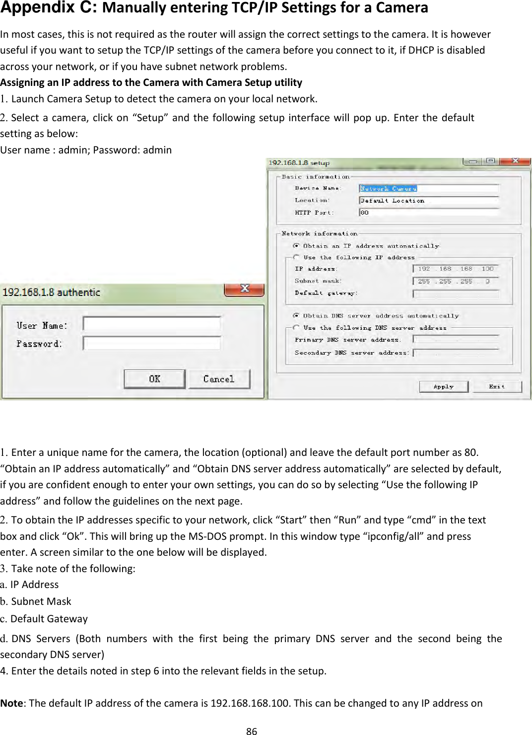
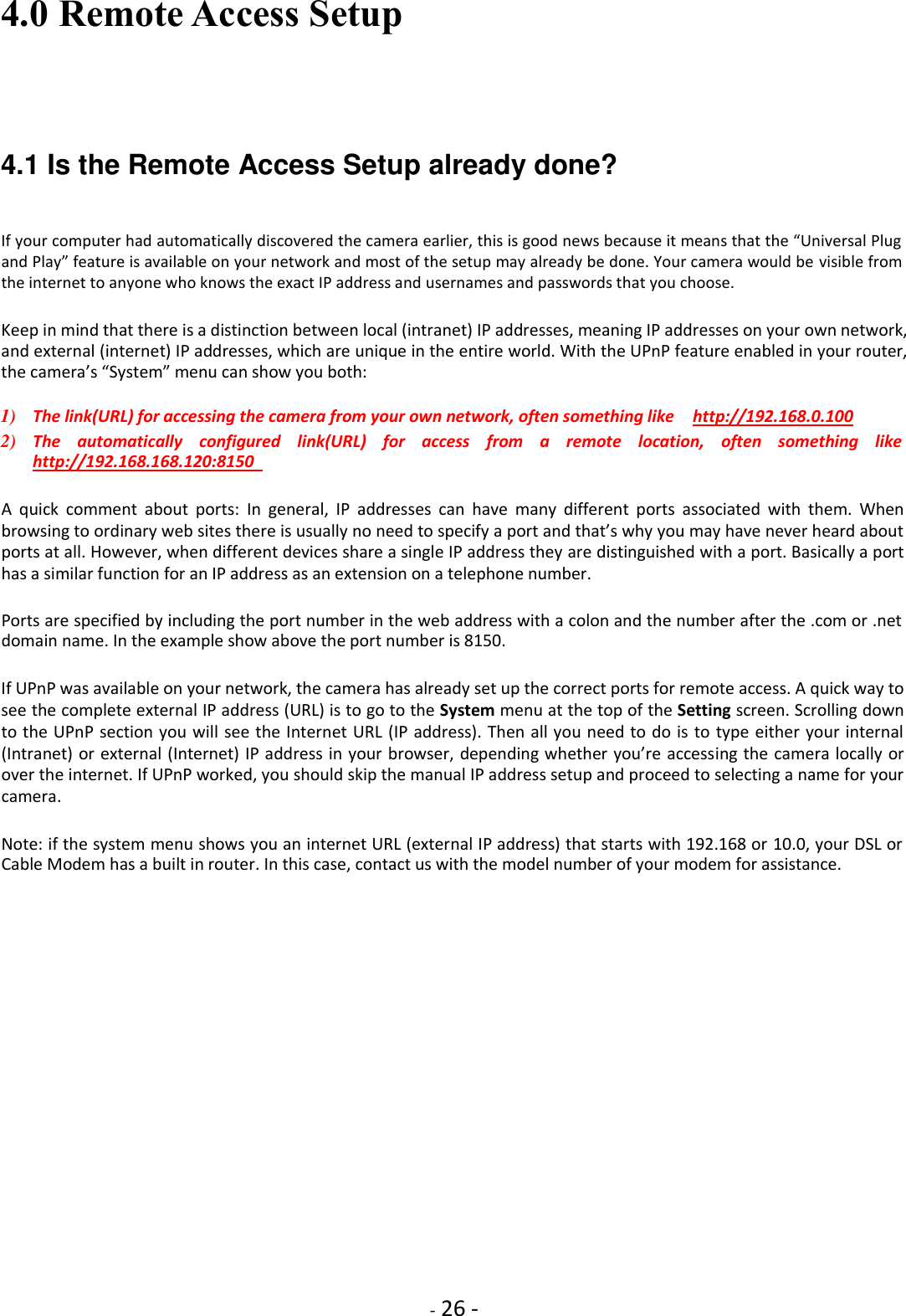
![- 29 - 4.3.1 TCP/IP SETUP --Manual Setup Step 1: Assigning a permanent IP address for your camera on your local network (Without UPnP) On your home network (LAN) all your computers, printers and other network connected devices have an IP address. In every IP address there are 4 groups of digits that can each vary from 1 to 255. For your home network the first 3 numbers are already determined by your router’s address, which is typically something like 192.168.0.1 or 192.168.1.1 or 10.0.1 To pick a permanent address for your camera you first need to know your router’s IP address. It is shown in your camera’s “system” menu (at the top of the setting screen) if you scroll down to “Default Gateway”. The router’s IP address determines the first 3 groups of digits for your camera’s IP address. Now we need to select a valid number for the last group of digits. We don’t simply pick a random number because we have to avoid numbers that are already taken or could be used by your router. The router uses addresses in a range set aside for this purpose (called the DHCP range). For many routers, this DHCP range is from 2 to 100 but you’ll have to check your specific router’s DHCP menu. Sometimes this is shown as start and end address, or start address plus number of available addresses. Why is this important? We want to select an address outside this range to make sure that your router would never pick this address for another device. For example, if your router uses the DHCP range from 192.168.0.2 to 100, You could choose 192.168.0.101 as a permanent IP address. Conversely, if your router uses DHCP addresses from 100 to 255, you could use 192.168.0.50 to be outside the range. Never use addresses that end in .0 or .1, since that is reserved for your router, and never use addresses that end in a number higher than 255 since that is the highest possible limit. Now that you have picked a local IP address for your camera, then go to the Camera Settings menu, then select “Network” and “TCP/IP Setup” : The camera is setup to obtain an IP address automatically (DHCP) from your Network by default, so these settings should not be needed by most users. If your network supports a DHCP server (e.g. router) select this option to have the IP address is assigned automatically. If you select Obtain an IP address automatically you should select Obtain a DNS Server address automatically. [Obtain an IP address automatically (DHCP)]](https://usermanual.wiki/Anbash-Technology/NC335SPW/User-Guide-3167460-Page-27.png)
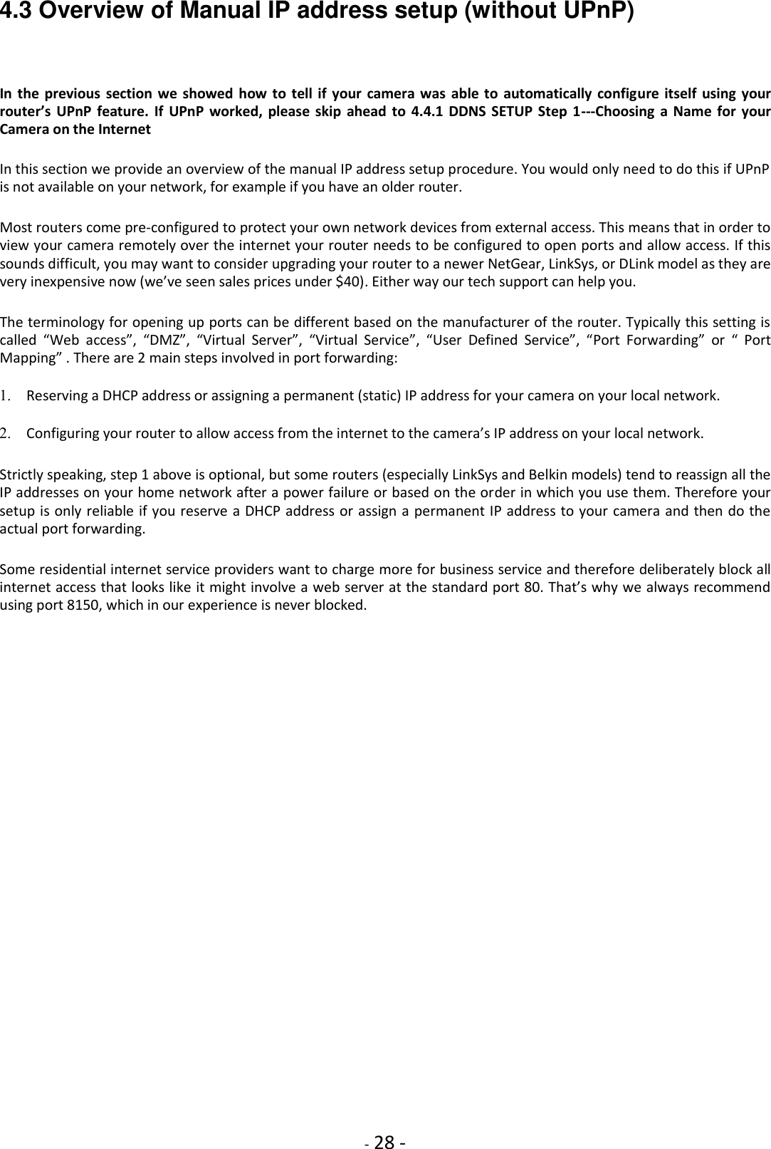
![- 30 - [Use the following IP address] Select this option when a fixed IP is required. [IP address] Type the IP address of your camera (Required). [Subnet mask] Type the subnet mask (Required). [Default gateway] Type the default gateway (Required). [Primary DNS IP address] Type the IP address of the primary DNS server, if necessary (Optional). [Secondary DNS IP address] Type the IP address of the secondary DNS server, if necessary (Optional). [HTTP port number] The default HTTP port number is 80. [RTSP port range] In order to view video over RTSP the router should be setup to forward a port in the range 30000 to 30100 to the camera’s IP address using UDP with an internal port in the range of 30000 to 30100. If you wish to assign the IP address manually, use this page to enter the address detail. 1. Click on “use the following IP address”. Then enter the IP address you picked that is outside your router’s DHCP range. 2. Do not change the subnet mask. The default setting of 255.255.255.0 is correct unless you have a very unusual home network. 3. Then enter your own router’s address in the “Default Gateway” box. Note that the first 3 groups of digits should be the same as your camera’s IP address. Usually the last digit is 1, sometimes it is 254. Note: It is very important to add the “Default Gateway” when assigning static local IP. While the camera gets this information automatically from the router when using DHCP, the camera will not obtain this information if a local IP address is assigned manually. 4. Then click on “Use the following DNS server” and Leave DNS server settings blank or enter both the primary and secondary DNS addresses that you obtained from your router menu or from your computer’s network connection menu. 5. HTTP/RTSP PORT: Leave it the default setting. The HTTP port is usually 80. 6. RTP port range: Leave it the default setting or enter the RTP port as below: The RTP port range should start at 30000 for your first camera. For all additional cameras the start of the range increase by 2, for example your 2nd camera would have a starting RTP port of 30002, the 3rd camera would have 30004, 4th camera at 30006 etc. After you click on “Apply”, you need to log in to the camera at the address you just picked. Remember to add the http:// in front of the IP address, as in http://192.168.168.120. If your port is not 80 you need to add the port too. From now on , regardless of what computers or other devices you have on your own network and regardless of the order that you turn them on or off, you camera’s IP address will always be the same. On some routers, for example some older models of Leviton or NetGear, you may also need to tell your router about the network camera’s IP address, so that it shows up as a known device on your network.](https://usermanual.wiki/Anbash-Technology/NC335SPW/User-Guide-3167460-Page-28.png)
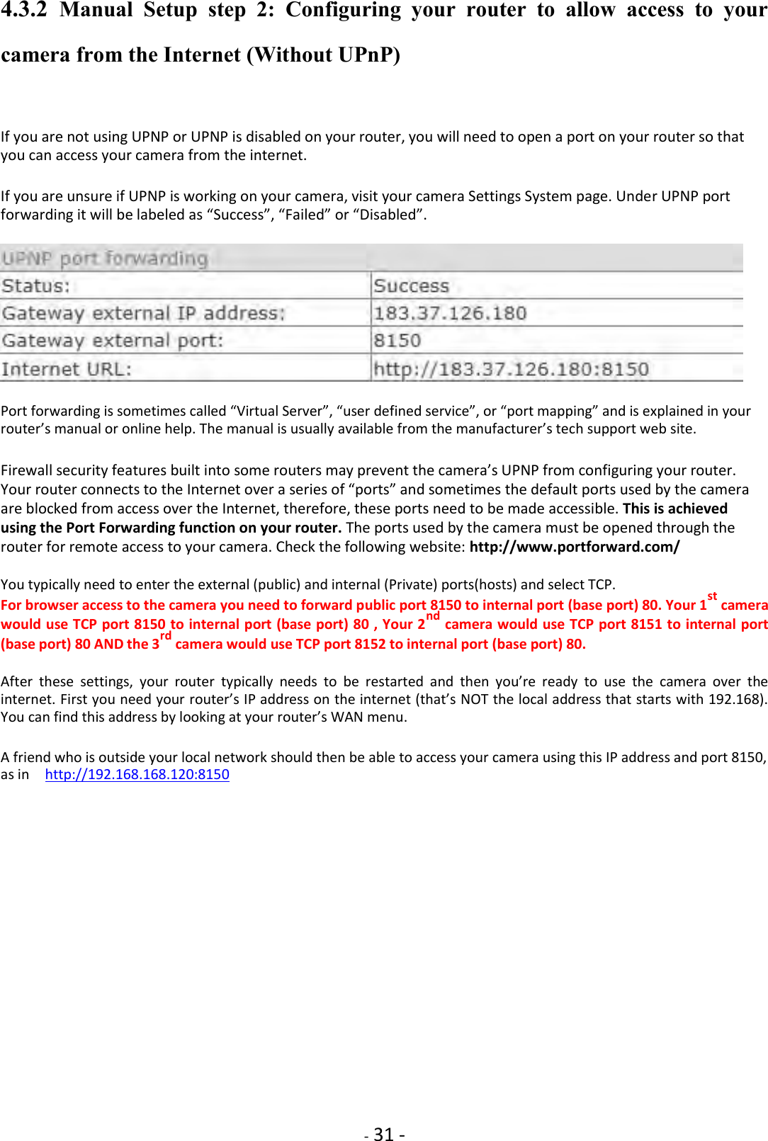
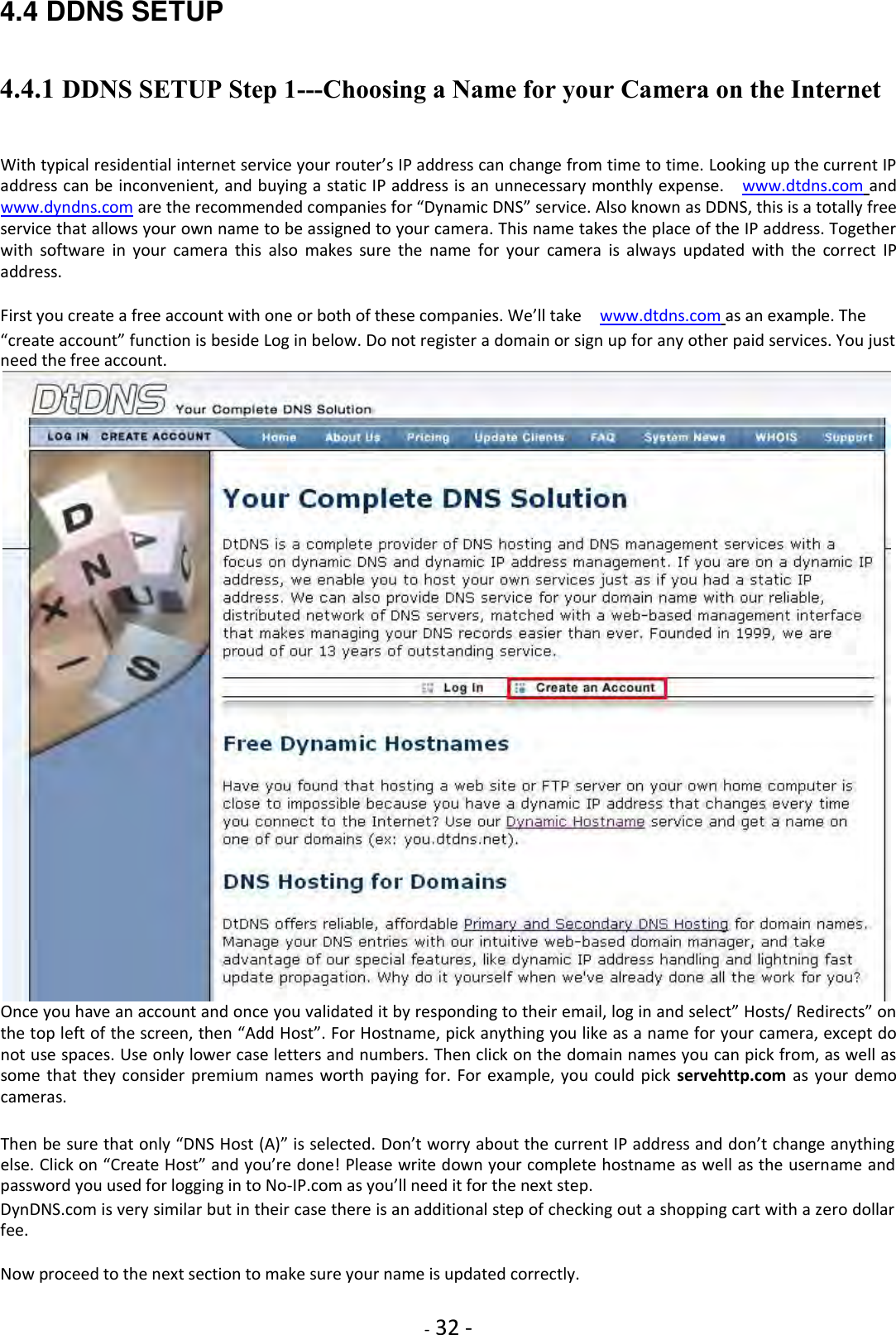
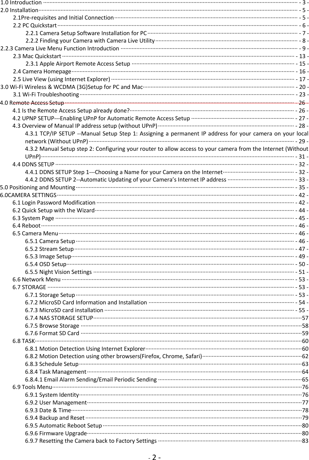
![- 33 - 4.4.2 DDNS SETUP 2--Automatic Updating of your Camera’s Internet IP address In the previous step we set up a name for your camera. To make sure that this hostname always corresponds to the correct IP address for your camera we have to make sure it is updated automatically when there is a change. Dynamic DNS (DDNS) is simply a way of using a static hostname to connect to a dynamic IP address. When connected to your ISP, you are assigned a temporary IP address. DDNS services keep track of your IP address and route your Domain name to that address when you wish to connect to the camera from a remote location. There is no need for client software. Our IP cameras have a DDNS menu that allows you to enter your hostname information. This DDNS menu is under “Network” in the camera’s “Settings”. Be sure to select the DDNS provider, for instance if you signed up with No-IP.com you should select No-IP in the camera’s DDNS menu. [DDNS] Enable or disable DDNS connection. Click “Enable” for the rest of the options to appear. [Service Provider] Select a provider from the drop down list then click “Register”. This will take you to the service provider’s website where you can register your own personal host name. Please follow the instructions on the provider’s site, and then return to this page to enter the details. [Host Name] Enter the host name you have registered (e.g. yourname.dtdns.net). [User Name] Enter the user name for the account you registered with the serviceprovider. [Password] Enter the password for the account you registered with the service provider. [Re-type password] Re-confirm the password. Now you have setup an easily accessible external address for your camera, you now need to setup and confirm an external port for your camera. This is covered in the UPnP section. Please note: if you have only just registered your DDNS account, it may take a while your account is activated and full registered on the internet. Some of the DDNS service listed offer free paying service. A free account is more than adequate for a camera to use. After you enter your account and hostname information and UPNP is enabled, you can go to the camera’s “System” menu at the top of the Settings screen and scroll down to the DDNS section. If it worked, the camera’s external address will be listed under “Internet URL”. If it says “Updating” or Unavailable” you should double check your account settings. No-IP.com uses your complete email address as user name, and the password required in this menu is the one you created during No-IP account setup. If successful the camera will show you the complete external URL for your reference. The external address using DDNS is made up of two parts – your DDNS account address and the port you opened](https://usermanual.wiki/Anbash-Technology/NC335SPW/User-Guide-3167460-Page-31.png)
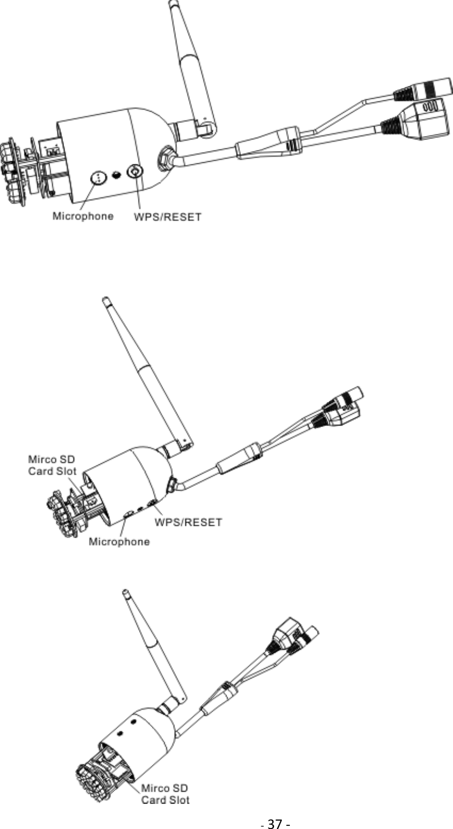

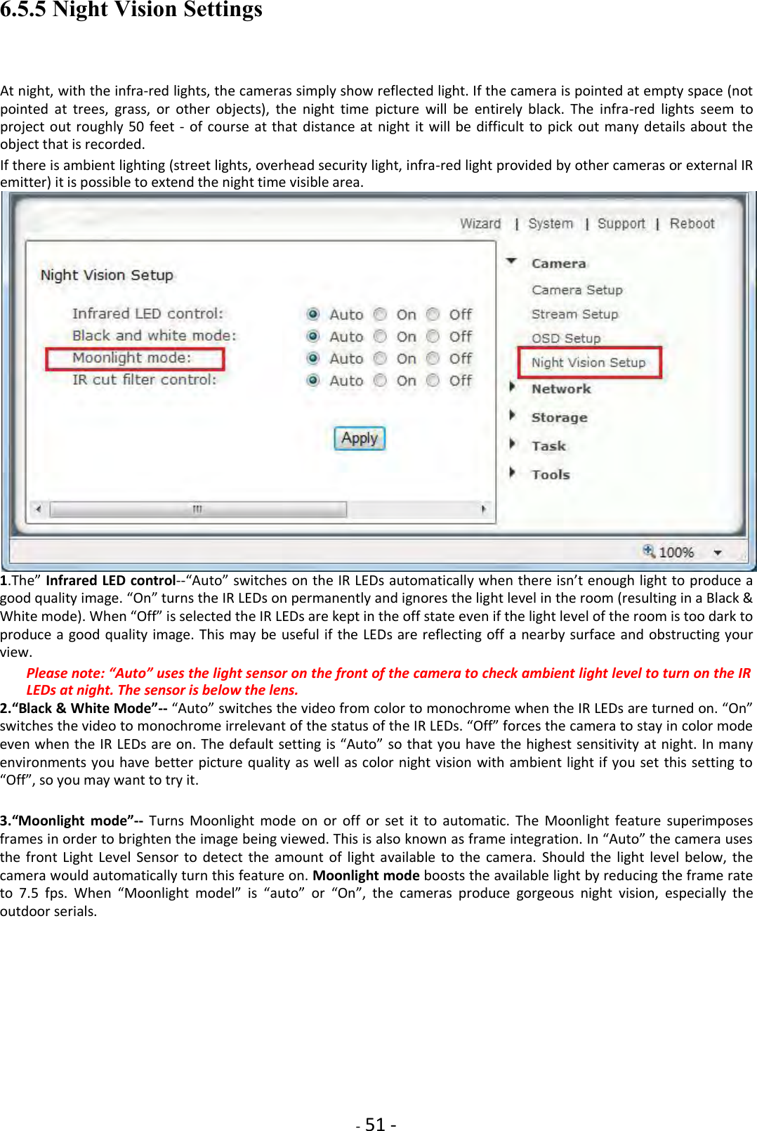
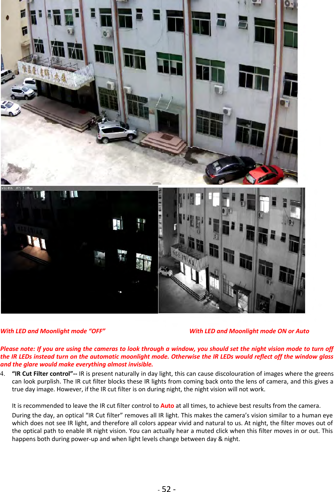
![- 46 - 6.4 Reboot Click Reboot in the Header Menu to access the Camera Reboot page to restart the camera. Rebooting the camera will retain all the settings and configurations. A reboot is normally necessary when you insert a microSD card into the camera. 6.5 Camera Menu 6.5.1 Camera Setup The Camera menu is located on the right of the Settings screen. When you click on the word “Camera”, a sub-menu of camera setup options will be displayed. For most users, many of these settings can be left as default. Camera Setting Options System: [Enable privacy mode] Videos will not be seen. [Power LED light] Turns off the camera front LED on or off Camera: [Light Frequency] Two options: 50Hz & 60Hz. This should be set according to the mains frequency of the country the camera is being used in. For EU this would be 50Hz. For the USA this would be 60Hz. [Enable image mirror] Display a mirrored view of the video. [Enable image flip vertical] Display video upside down – useful if you have installed the camera upside down. Microphone: [Microphone] Enables or disables the built-in microphone. [Volume] Adjusts the sensitivity of the microphone from 0~10 where 0 is the lowest. Click Apply to confirm your setting.](https://usermanual.wiki/Anbash-Technology/NC335SPW/User-Guide-3167460-Page-44.png)
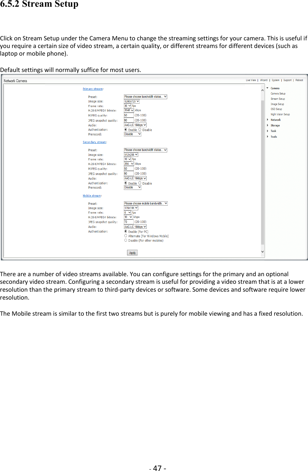
![- 48 - Stream Setting Options [Present] There are five pre-programmed stream profiles for quick set-up. Please choose the one according to your bandwidth. [Image size] Image resolutions available are as follows: 480P Model: 640 x 480(VGA), 320 x 240(QVGA), 160 x 120 (QQVGA). The mobile stream has a fixed image size of 176x144. HD 720 Model: 1280x720 (HD720p), 768x432, 512x288, 256x144). The mobile stream has a fixed image size of 176x144. HD 1080 Model: 1920x1080 (HD1080p), 1280x720 (HD720p), 768x432, 512x288, 256x144. The mobile stream has a fixed image size of 176x144. [Frame rate] Twelve options: 1/2/3/4/5/6/8/10/15/20/25/30 frames per second (fps). The frame rate is automatically determined by the camera and this depends on the network bandwidth available at the time. This frame rate setting imposes the maximum frame rate that the camera will transmit. [H.264/MPEG4 bit rate] Select H.264/MPEG4 bit rate. These settings determine the image quality, however higher bitrates require greater bandwidth. Please select the appropriate settings according to your connection speed and network traffic. If you are experiencing jerky video it may be necessary to decrease the bitrate. [MJPEG Quality] This sets the quality of the video when viewing the camera using Motion JPEG (without audio). It can be from 20 to 100 where 100 is the best quality. [JPEG snapshot Quality] The quality of the snapshot saved using Live View page (Internet Explorer only). It also affects the quality of the snapshot to be uploaded to an FTP Server. It can be from 20 to 100 where 100 is the best quality. [Audio] Select or disable the audio bit rate. [Authentication] Select or disable MPEG4 RTSP authentication. Clicking on the name of the stream will display various paths to the paths to the particular video stream](https://usermanual.wiki/Anbash-Technology/NC335SPW/User-Guide-3167460-Page-46.png)
![- 49 - 6.5.3 Image Setup [Brightness] make the image brighter or darker by a specified amount. When increasing brightness, you may find that you lose some contrast on the brightest details in the image while the rest of the image has the same contrast as before. [Contrast] Contrast is defined as the separation between the darkest and brightest areas of the image. Increase contrast and you increase the separation between dark and bright, making shadows darker and highlights brighter. Decrease contrast and you bring the shadows up and the highlights down to make them closer to one another. Adding contrast usually adds "pop" and makes an image look more vibrant while decreasing contrast can make an image look duller. [Hue] Change is similar to rotating a color wheel to select a different mixture of colors [Saturation] Saturation is similar to contrast, however instead of increasing the separation between shadows and highlights, we increase the separation between colors. [Sharpness] Sharpness can be defined as edge contrast, that is, the contrast along edges in a photo. When we increase sharpness, we increase the contrast only along/near edges in the photo while leaving smooth areas of the image alone. [Auto Exposure Target] Automatic exposure (abbreviation: AE) mode automatically calculates and adjusts exposure settings to match (as closely as possible) the subject's mid-tone to the mid-tone of the photograph. Exposure is a combination of the length of time and the illuminance at the photosensitive material. Exposure time is controlled in a camera by shutter speed and the illuminance by the lens aperture and the scene luminance. Slower shutter speeds (exposing the medium for a longer period of time), and greater lens apertures (admitting more light), and higher-luminance scenes produce greater exposures.](https://usermanual.wiki/Anbash-Technology/NC335SPW/User-Guide-3167460-Page-47.png)
![- 50 - 6.5.4 OSD Setup Click on OSD Setup under the Camera Menu to change the on-screen display parameters of the camera. On Screen Display Setting Options [OSD] Enable or Disable the On Screen Display. OSD Options [Display date and time] Set the OSD to display the Date and Time of the camera. Please note that this function will simply display the date and time that has been programmed in the camera and therefore the time and date may be incorrect unless the camera is synchronized to a time and date server on the internet. This is accessible under the Tools menu and will be covered in more detail in the manual. [Display system name] Set the OSD to display the System Name of the camera. The system name can be modified from the System Identity page, accessible under the Tools menu, and will be covered in more detail in the manual. [Display the text below] Set the OSD to display specific text. Use the text field to input the desired text. Click Apply to confirm your setting.](https://usermanual.wiki/Anbash-Technology/NC335SPW/User-Guide-3167460-Page-48.png)
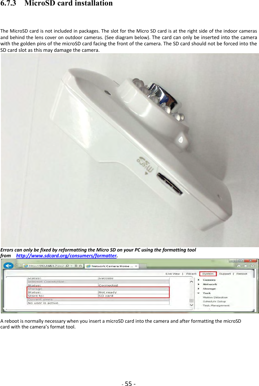
![- 53 - 6.6 Network Menu The Network menu is located on the right of the Settings screen. When you click on the word “Network”, a sub-menu of network setup options will be displayed. Skip the wireless setup chapter, please check page 18 to 21. Skip the TCP/IP setup chapter, please check page 25 to 26. Skip the DDNS setup chapter, please check page 28 to 30. Skip the UPnP setup chapter, please check page 23. Skip the P2P setup chapter, please check QuickGuide. 6.7 STORAGE 6.7.1 Storage Setup When the camera powers up with a Micro SD present in the slot, Enable “storage” and select store to “SD card”, and then select “format the Micro SD”. The Storage menu is located on the right of the Settings screen. When you click on the words “Storage”, a sub-menu of options will be displayed The camera can record video direct to virtually an NAS drive or to its internal microSD memory card. [Storage] Select Enable to enable storage option. [Storage Select] Select whether you want to record on NAS or microSD card. [Store directory] This is the folder that videos will be saved to. [Max Space] Storage capacity the camera will use on the chosen storage. [Max files] The maximum number of files for all the videos can be recorded before overwriting. Click Apply to confirm your setting.](https://usermanual.wiki/Anbash-Technology/NC335SPW/User-Guide-3167460-Page-51.png)
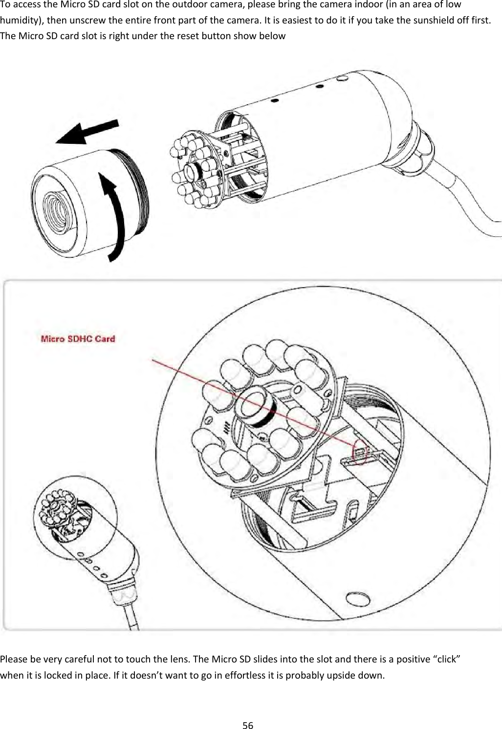
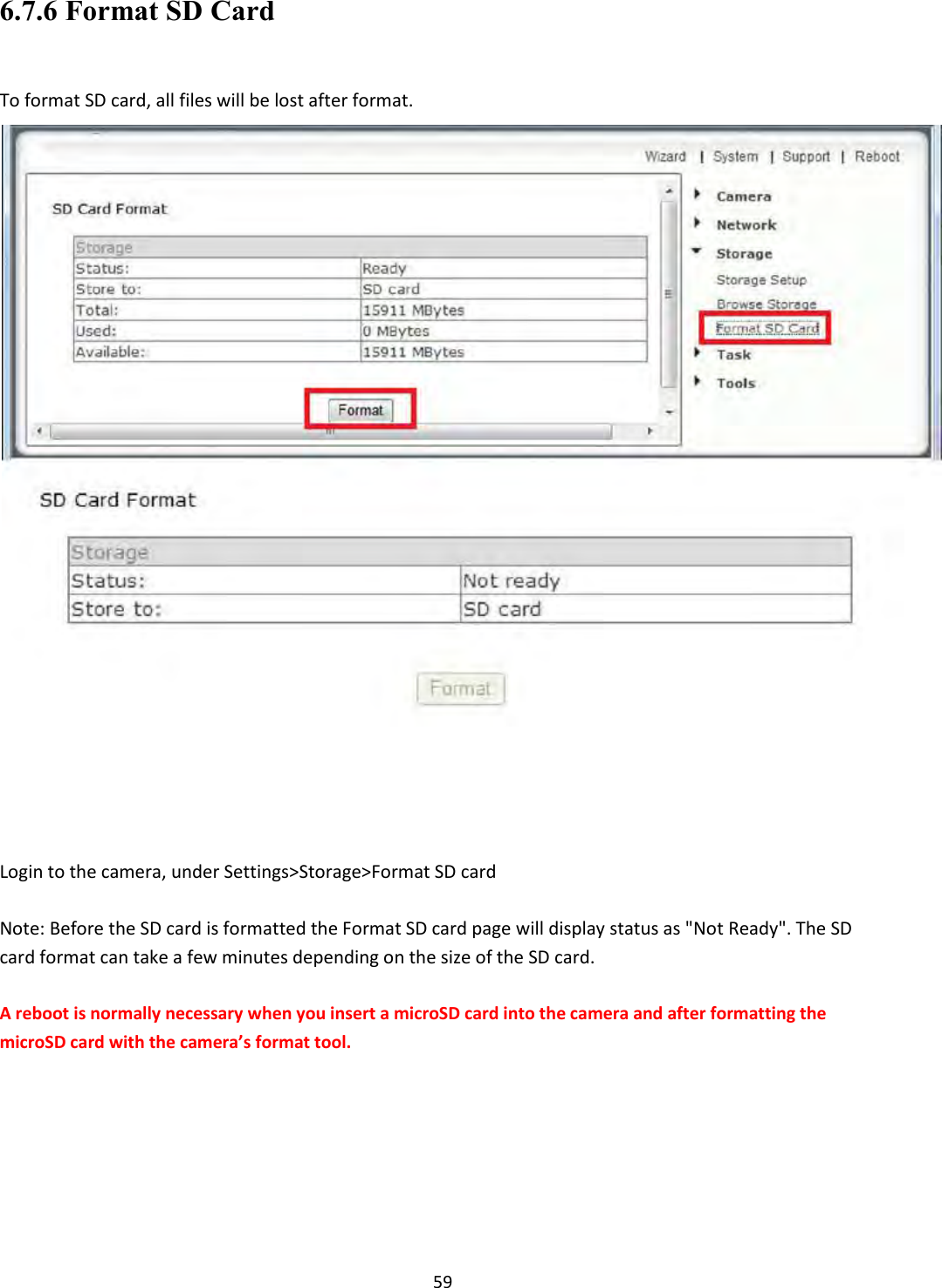
![57 When done, please be careful when screwing the front part back on to make sure the threads are engaging nicely. Do not use any tools, hand tight is good enough. 6.7.4 NAS STORAGE SETUP [NAS remote path] This is the address & path where to save the files on NAS Drive (up to a maximum of 2 directory levels). [Authorization1] Select whether authentication is required by the NAS Drive. [User name] & [Password] Type the user name and password of the NAS Drive. This field is required if your NAS Drive requires authentication. Click Apply to confirm your setting. Please note : After the setting on “Storage“ and Micro-SD card or NAS status is ready. You can go to next chapter “Task”, and configure motion detection to initiate the snapshots or video recording to Micro SD card or NAS.](https://usermanual.wiki/Anbash-Technology/NC335SPW/User-Guide-3167460-Page-55.png)
![58 6.7.5 Browse Storage Clicking on Browse Storage will take you to the following screen where you can view or download the contents of the storage drive. The resulting video files can be viewed with the free QuickTime for Windows or Mac. You do not need QuickTime X or Pro unless you want to compress the resulting video to iPhone/iPod format. Shorter video clips will download much faster. If you have many video files you could also remove the Micro SD card and access it directly from your computer (with suitable adapter if needed). This is only practical for indoor cameras due to easy accessibility of the Micro SD card slot at the bottom. [All] Enables you to view and delete all the files recorded. [Snapshot on Alarm] Enables you to view and delete snapshots which were recorded upon motion detection [Snapshot at Interval] Enables you to view and delete all the snapshots which were recorded on periodicalbasis [Record on Alarm] Enable you to view and delete all the videos which were recorded upon motion detection [Continuous Record] Enables you to view and delete all the videos recorded according to the continuous record schedule. The browse storage page shows a summary of all the files saved for a specific function. To access the files please click on the relevant link and this will display all the files.](https://usermanual.wiki/Anbash-Technology/NC335SPW/User-Guide-3167460-Page-56.png)
![60 6.8 TASK 6.8.1 Motion Detection Using Internet Explorer Motion Detection can trigger an alarm that sends images via e-mail or FTP (File Transfer Protocol). You can set up to four different Motion Detection windows. The camera refers to motion detection as an “alarm”. You can select what you want the camera to do once the motion is detected. In general, motion detection works by comparing the current video frame with the averages of the previous video frames. Any difference is considered to be motion, and the sensitivity adjustment can be used to make the camera more aware or less aware of small amounts of motion. Moving an object (a person or a car, for instance) directly toward the camera may not trigger motion detection until the object is within 10 to 15 feet of the camera. Motion detection seems to work well when the object is moving from one side of the picture to the other side, often triggering in a second or less. The factory default setting for motion detection is a single motion detection window covering the entire visible area. The “Motion Detection” menu allows you to designate up to 4 separate windows with individually adjustable sensitivity. After selecting “Motion detection” from the main settings screen, you may need to expand the size of the display window towards the right to see the 4 controls for individual motion detection windows. Each window can have individually adjustable sensitivity and threshold. Please note that this “Motion Detection” menu is entirely optional and is generally not used unless you have very specific requirements to treat motion on some parts of the screen different from other parts. [Window] Check this box to enable the window.](https://usermanual.wiki/Anbash-Technology/NC335SPW/User-Guide-3167460-Page-58.png)
![61 [Threshold] Determines at what point the alarm is triggered. A lower threshold means less motion is needed to trigger the alarm. A higher threshold means more motion is needed to trigger the alarm. Threshold is indicated by the blue bar when motion is detected. [Sensitivity] Determines how easily the camera detects motion. Lower sensitivity means the camera is less likely to detect motion. Higher sensitivity means the camera is more likely to detect motion. Note: Sliding the Sensitivity bar to the left will decrease the sensitivity of the motion detection i.e. ‘More’ movement is required to trigger the alarm. Internet Explorer can show you a live indicator for motion: When there is motion, a blue level appears between the sensitivity and threshold slider as shown in the picture. More blue means more motion. To trigger an alarm (and hence send out emails or upload to an FTP server etc) the detected amount of motion needs to be larger than the threshold setting. If the blue level does not reach the threshold setting the motion is ignored. The best way to configure these settings is to adjust the settings and have someone walk in front of the camera until your feel you are getting the required results. This trial and error method make take quite long to get right but it’s the best way to obtain good results. Please note: Motion detection in Internet Explorer uses the ActiveX plug-in. You will need to install or enable this plug-in if you do not have it. To check you have ActiveX enabled visit http://www.pcpitstop.com/testax.asp To reduce the chance of false alarms you would increase the threshold (move threshold slider to right) or decrease sensitivity (move sensitivity slider to left) .](https://usermanual.wiki/Anbash-Technology/NC335SPW/User-Guide-3167460-Page-59.png)
![62 6.8.2 Motion Detection using other browsers(Firefox, Chrome, Safari) [Window] Check this box to enable the window. [Threshold] Determines at what point the alarm is triggered. A lower threshold means less motion is needed to trigger the alarm. A higher threshold means more motion is needed to trigger the alarm. Threshold is indicated by the blue bar when motion is detected. [Sensitivity] Determines how easily the camera detects motion. Lower sensitivity means the camera is less likely to detect motion. Higher sensitivity means the camera is more likely to detect motion. To reduce the chance of false alarms you would increase the threshold (move threshold slider to right) or decrease sensitivity (move sensitivity slider to left) . Please note: Motion detection in other browsers uses the Adobe Flash plug-in. You will need to install the Flash plug-in if you do not have it. To check you have the latest version of Flash, visit http://updateflash.org](https://usermanual.wiki/Anbash-Technology/NC335SPW/User-Guide-3167460-Page-60.png)
![63 6.8.3 Schedule Setup The alarm that the motion detection triggers can be set to be active or inactive at certain times of the week. By default, the schedule is set to be “active” at all times “always”. However you can set the schedule not to trigger alarms at certain times (useful for instance if you don’t want alarms to go off while your office is open from 9am until 5.30pm). You can set up to 4 schedules, and you can use these to send alarms to different places – such as emails, FTP or SD card. Schedule Setup Options [Schedule ID] Select the ID, you can save up to 4 schedules and use them for different purposes. [No.] Setup the specified times in every Schedule ID, you can save up to 8 specified times and use them for different purposes. [Enable] Activates the alarm on specified times. Ticking this box to activate the alarm on the specified times. [Start time] Start time of the alarm. [End time] End time of the alarm. [Days] Ticking this box activate the alarm daily on the specified times from Monday to Sunday. Click Apply to confirm your setting](https://usermanual.wiki/Anbash-Technology/NC335SPW/User-Guide-3167460-Page-61.png)
![64 6.8.4 Task Management There are various tasks you can enable on your camera. This section will explain the various tasks and their functions [Enable] Enable task. [Schedule] Option to choose always or set a particular schedule. Check Schedule setup to select the right schedule ID for your task. [Task] Task function. Click on the task to login the task setting screen below. Click Apply to confirm your setting](https://usermanual.wiki/Anbash-Technology/NC335SPW/User-Guide-3167460-Page-62.png)
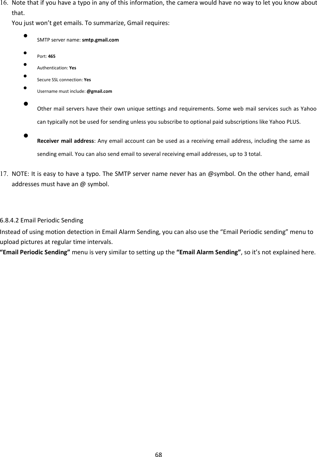
![66 Note: Gmail requires that you go to your account settings on Gmail.com and enable the POP feature (Post Office Protocol). If your Gmail account does not have POP enabled, the camera will not be able to send email. [Enable] Enable task. [Schedule] Option to choose always or set a particular schedule. Check Schedule setup to select the right schedule ID for your task.](https://usermanual.wiki/Anbash-Technology/NC335SPW/User-Guide-3167460-Page-64.png)
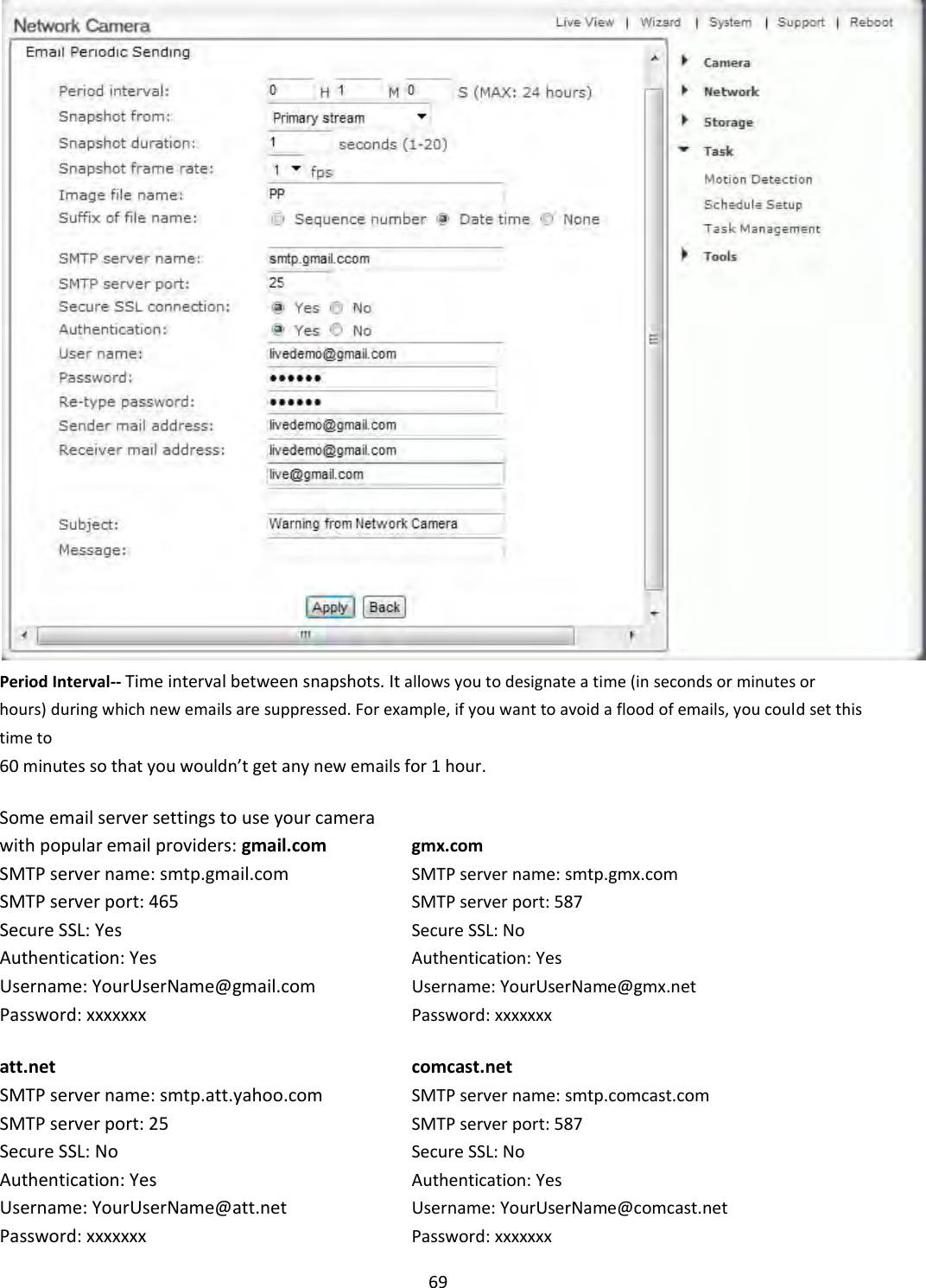
![67 [Task] Task function. Click on the task to login the task setting screen below. Click Apply to confirm your setting 1. Snapshot from--- Select snapshot stream source which can be “Primary stream” , “Secondary stream” and “ Mobile Stream” . For smaller pictures you can select from “Secondary stream”. 2. Snapshot Duration-- The number of seconds that the camera should keep sending emails with attached image after motion stops. 3. Snapshot Frame Rate-- The number of frames per seconds that the camera should keep sending images at when an alarm is triggered. If “Snapshot duration” had a value of 4 and “snapshot frame rate” had a value of 2, you would be getting 2 images each second for 4 seconds in a row, meaning 8 pictures total for each motion detection event. 4. Alarm Interval-- This is the number of seconds for which the camera should stop sending e-mail alerts after the first set. Setting the time to 0 disables this feature. It allows you to designate a time (in seconds) during which new emails are suppressed. For example, if you want to avoid a flood of emails, you could set this time to 3600 seconds so that after a motion detection event you wouldn’t get any new emails for at least 1 hour. 5. SMTP server name--Type the name or IP address of the SMTP server you want to use for sending the e-Mails. Please note that some networks do not allow e-mail relaying. Check with your system administrator or Internet service provider for more details. 6. SMTP server port-- The port number of the e-mail server (default is 25) 7. Secure SSL connection--Select whether your SMPT server requires an SSL connection. 8. Authentication--Select whether authentication is required by the SMTP server. 9. User name] & Password--Type the user name and password of the e-mail account you wish to use. This field is required if your SMTP server requires authentication. 10. Re-type password-- Re-type the password. 11. Sender e-mail address--Type the e-mail address of the account you are using to send the e-mail. This will be the address the emails come from. 12. Receiver e-mail address--Type the recipients’ e-mail addresses for who you want the emails to be sent to. Up to 3 addresses can be entered. 13. Subject--Subject of the e-mail that is sent. Entering a relevant subject will help identify the alarm better. i.e. “Garage Alarm” 14. Message--Type the text you wish to appear in the e-mail. E.g. this is to notify you that your alarm has been triggered. Notes: Email settings can be obtained from your e-mail service provider. An SMTP email account is required – these are very common if you use POP3 email and some IMAP servers. A true IMAP server will not work. Some ISPs won’t let you use any other SMTP server other than their own (British Telecom BT is a good example of this). 15. Click Apply to confirm your setting.](https://usermanual.wiki/Anbash-Technology/NC335SPW/User-Guide-3167460-Page-65.png)
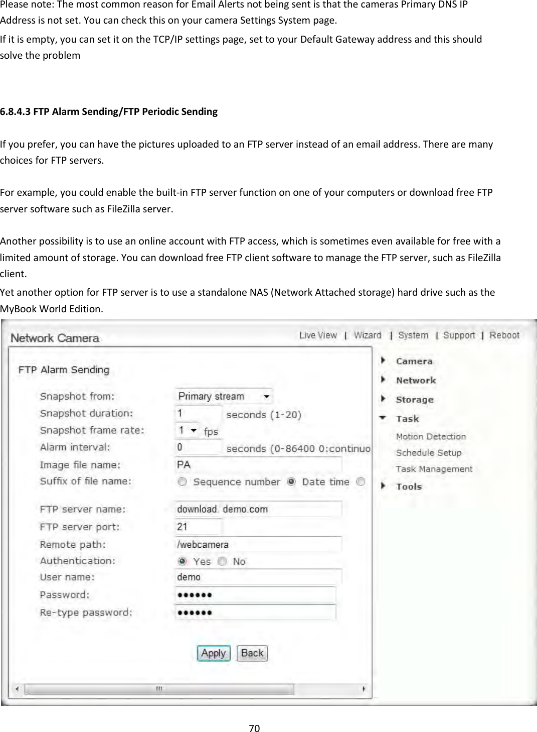
![71 Setup of the FTP alarm sending menu is very similar to setting up the Email alarm Sending/Email periodic sending, so we don't explain the Snapshot from, Snapshot duration, Snapshot frame rate, Alarm interval,Image file name, Suffix of file name again here. [Enable] Enable task. [Schedule] Option to choose always or set a particular schedule. Check Schedule setup to select the right schedule ID for your task. [Task] Task function. Click on the task to login the task setting screen below. Click Apply to confirm your setting [FTP server name] Type the name or IP address of the FTP server. At a minimum you need the IP address (FTP server name) for your FTP server. The port is almost always 21, and typical servers need a username and password which means “Authentication” should be set to “Yes”. [FTP server port] The port number of the FTP server (default is 21). [Remote path] Input the file directory. It is an optional setting to specify a folder on the FTP server. If you decide to use this feature, you have to make sure that the folder exists on the FTP server with the exact same spelling. [Authentication] Select whether authentication is required by the FTP server. Choose “No” for anonymous access. [User name] Type your FTP user name. [Password] Type your FTP password. [Re-type password] Re-type your password. Click Apply to confirm your settings. Instead of using motion detection in “FTP alarm sending”, you can also use the “FTP Periodic sending” menu to upload pictures at regular time intervals. [Period Interval]--Time interval between snapshots. It allows you to designate a time (in seconds or minutes or hours) during which new emails are suppressed. For example, if you want to avoid a flood of emails, you could set this time to 60 minutes so that you wouldn’t get any new emails for 1 hour. Note:The menu option for “HTTP alarm sending” and “ HTTP Periodic sending” are not explained here since HTTP servers are only used by network professionals. 6.8.4.4 Snapshot to Storage on Alarm/ Snapshot to Storage Periodically](https://usermanual.wiki/Anbash-Technology/NC335SPW/User-Guide-3167460-Page-69.png)
![72 [Snapshot from] Select snapshot stream source. [Snapshot duration] The number of seconds that the camera should keep sending images after motion stops. [Snapshot frame rate] The number of frames per seconds that the camera should keep sending images at when an alarm is triggered. [Alarm Interval]--Number of seconds for which the camera should stop sending e-mail alerts after the first set. Setting the time to 0 disables this feature. It allows you to designate a time (in seconds) during which new pictures are suppressed. For example, if you want to avoid a flood of pictures, you could set this time to 3600 seconds so that after a motion detection event you wouldn’t get any new pictures for at least 1 hour. [Image file name] Name of file image snap shots are saved to [Suffix of file name] Choose between Sequence number and Date Click Apply to confirm your settings. Instead of using motion detection (Snapshot to Storage on Alarm), you can also use the “Snapshot to storage periodically” menu to take snapshots at regular time intervals (Snapshot to Storage Periodically) The “Period Interval” allow you to designate a time (in seconds or minutes or hours) during which new snapshots are suppressed. For example, if you want to avoid a flood of snapshots, you could set this time to 60 minutes so that you wouldn’t get any new snapshots for 1 hour.](https://usermanual.wiki/Anbash-Technology/NC335SPW/User-Guide-3167460-Page-70.png)
![73 6.8.4.5 Record to Storage on Alarm/ Record to Storage Continuously [Enable] Enable task. [Schedule] Option to choose always or set a particular schedule. Check Schedule setup to select the right schedule ID for your task. [Task] Task function. Click on the task to login the task setting screen below. Click Apply to confirm your setting 1. [Record from]-- Select the stream from which it should record. It can be “Primary stream” , “Secondary stream” and “ Mobile Stream” . For smaller pictures you can select from “Secondary stream” or “Mobile Stream”. 2. [Post-recording time]--The number of seconds that the camera should keep recording video after motion stops. If there is any motion within this time the camera will keep recording until there is no motion for the duration of this parameter. It can be from 5 seconds to 24 hours. 3. [Split duration]-- This specifies the maximum duration of one file. If the recording goes on for longer than this parameter the camera will split the video into a number of files. 4. [Record thumbnail]-- Enable or disable thumbnail. 5. [Image file name] --Name of file image snap shots are saved to 6. [Suffix of file name]-- Choose between Sequence number and Date 7. Click Apply to confirm your settings. Instead of using motion detection (Record to Storage on Alarm), you can also use the “Record to storage continuously” menu to record video at 24 hours or as per your schedule. 6.8.4.6 Send files in storage to FTP server](https://usermanual.wiki/Anbash-Technology/NC335SPW/User-Guide-3167460-Page-71.png)
![74 [Enable] Enable task. [Schedule] Option to choose always or set a particular schedule. Check Schedule setup to select the right schedule ID for your task. [Task] Task function. Click on the task to login the task setting screen below. Click Apply to confirm your setting [FTP server name] Type the name or IP address of the FTP server. At a minimum you need the IP address (FTP server name) for your FTP server. The port is almost always 21, and typical servers need a username and password which means “Authentication” should be set to “Yes”. [FTP server port] The port number of the FTP server (default is 21). [Remote path] Input the file directory. It is an optional setting to specify a folder on the FTP server. If you decide to use this feature, you have to make sure that the folder exists on the FTP server with the exact same spelling. [Authentication] Select whether authentication is required by the FTP server. Choose “No” for anonymous access. [User name] Type your FTP user name. [Password] Type your FTP password. [Re-type password] Re-type your password. Click Apply to confirm your settings Note: Once successfully transferred, each original file on the Micro SD card is deleted.](https://usermanual.wiki/Anbash-Technology/NC335SPW/User-Guide-3167460-Page-72.png)
![75 6.8.4.7 Push Notification [Enable] Enable task. [Schedule] Option to choose always or set a particular schedule. Check Schedule setup to select the right schedule ID for your task. [Task] Task function. Click on the task to login the task setting screen below. Click Apply to confirm your setting [Post time]--The number of seconds that the camera should keep alarm message sending after motion stops. If there is any motion within this time the camera will keep sending alarms until there is no motion for the duration of this parameter. It can be from 5 seconds to 24 hours. [Alarm Interval]--Number of seconds for which the camera should stop sending alerts after the first set. Setting the time to 0 disables this feature. It allows you to designate a time (in seconds) during which new alerts are suppressed. For example, if you want to avoid a flood of alerts, you could set this time to 3600 seconds so that after a motion detection event you wouldn’t get any new alerts for at least 1 hour.](https://usermanual.wiki/Anbash-Technology/NC335SPW/User-Guide-3167460-Page-73.png)
![76 6.9 Tools Menu The Tools menu is located on the right of the Settings screen. When you click on the word “Tools”, a sub-menu of setup options will be displayed. 6.9.1 System Identity [System Name] Type a name to easily identify the camera. [System Contact] Type the contact name of the administrator of the camera. This is useful in large organizations. [System Location] Type the location of the camera. This is useful when using a multi-camera viewer program. Tip: The information you fill in can be displayed on the camera. It can help to distinguish different cameras on the network.](https://usermanual.wiki/Anbash-Technology/NC335SPW/User-Guide-3167460-Page-74.png)
![77 6.9.2 User Management Allows you to add or remove users who can view your camera. Useful if you want to allow others to view your camera, without having full admin rights. [Add] Up to 64 users (including the admin) can be created. Adding users: Click Add on the Camera User List page, then fill in a username and password (twice) and then click Add. To edit a user’s password: Click on the user name then enter the new password for that user twice and click Save. To delete a user: Click on the user name then click Delete. Note: A maximum of 16 users are allowed to access the camera simultaneously. As the number of simultaneous users increases, the overall performance will decrease. This is dependent on the network bandwidth, not the camera. [Allow anonymous access] This is to be used if you wish to share video with other users, without prompting them for a user name and password. This will allow the user free access to view the “Live View” page, whereas access to the Settings page will still be prohibited. [Authentication method] The "basic" authentication scheme is based on the model that the client must authenticate itself with a user-ID and a password. Digest Access is a more secure login method as the username and password are encrypted before being sent over the internet, however not all systems support Digest Access Authentication.](https://usermanual.wiki/Anbash-Technology/NC335SPW/User-Guide-3167460-Page-75.png)
![78 6.9.3 Date & Time Allows you to set the date and time - used for the timestamp of any files created by the camera [Current device time] Internal time of the camera. [Proposed device time] PC system time. On clicking Apply the internal time of the camera will be changed to this time. [Select to change the time zone for the device location] Choose your time zone. [Daylight saving time] tick the box to enable daylight saving time. [Date and Time format] Select the format of the date and time. [Auto time setting (SNTP)] Enable or disable the auto time setting to update to the server below. [Time server] Type the SNTP server name. There are suggestions included. Note: 1. If the SNTP server is not found the camera’s time will be synchronized with the PC time. 2. The camera keeps track of the time even when power is disconnected. Click Apply to confirm your settings.](https://usermanual.wiki/Anbash-Technology/NC335SPW/User-Guide-3167460-Page-76.png)
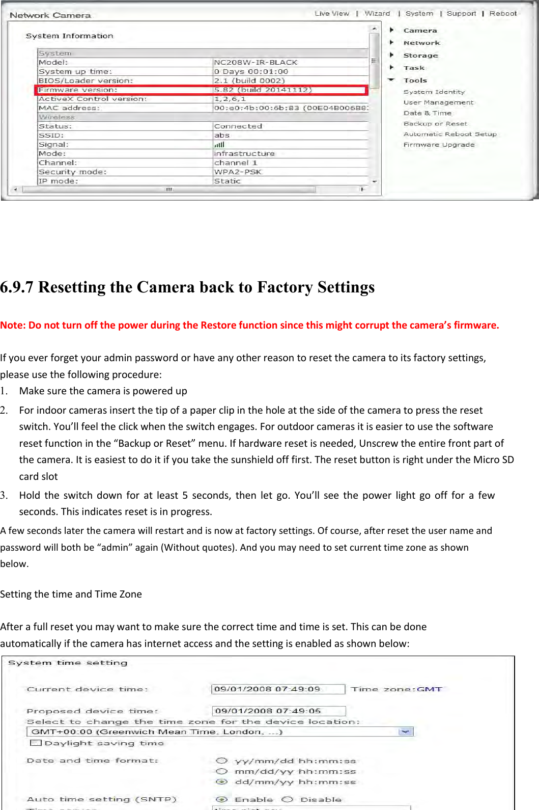
![79 6.9.4 Backup and Reset Allows you to reset the camera to factory defaults, backup the configuration in case of accidental reset and restore settings from a backup. [Reset] Click Reset to initialize the camera to default factory settings. All users and settings will be lost, requiring you to reconfigure the camera. [Backup] Click Backup to back-up the current configuration of the camera for future reference. Once you have your camera setup as you require, this is recommended. To restore a backup file: [Browse...] Click Browse... to search for a backup configuration you wish to upload to the camera, then click Restore. Note: Do not turn off the power during the Restore function since this might corrupt the camera’s firmware](https://usermanual.wiki/Anbash-Technology/NC335SPW/User-Guide-3167460-Page-77.png)
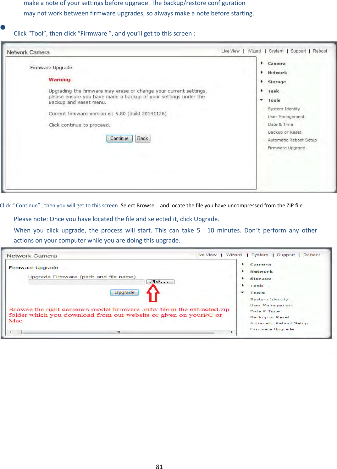
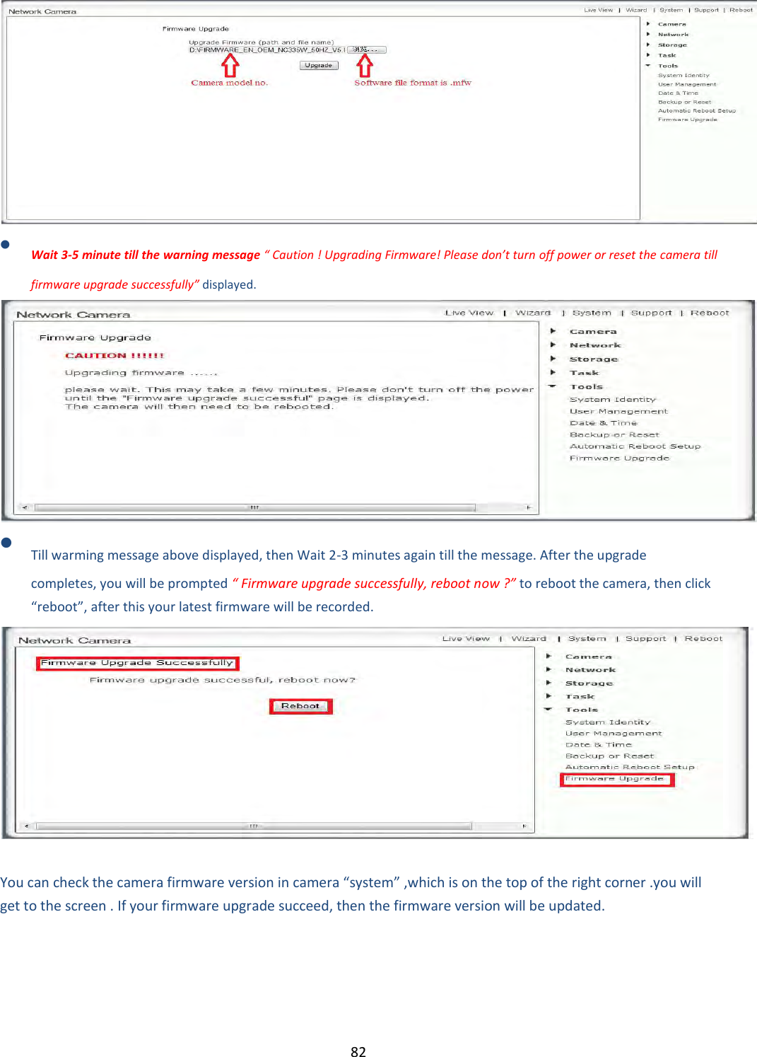
![80 6.9.5 Automatic Reboot Setup [Auto reboot] Enable task to keep camera automatic self-checking the connectivity status. [Reboot Time] Option to choose always or set a particular schedule. 6.9.6 Firmware Upgrade From time to time a new firmware may be released for your model of camera. To check for updates, consult with our technical support before firmware upgrade. Once you have downloaded the latest firmware, store it in a place that is easily to get to. The firmware is in a ZIP file, which is a compressed file format. You will need to move or copy the file from this compressed folder (some versions of Windows will allow you to do this, but if not, you will need a program like WinZip or WinRAR to unzip the file to a standard folder). This is very important as the firmware will not update properly if it’s left in the compressed state. TIPS We do recommend you update to the latest firmware for your camera whenever we release one to take advantage of new features and bug fixes. However, this is a serious process and can damage your camera if not done correctly. If your firmware is several versions out of date, upgrading straight to the latest one is perfectly fine, you do not need to install each and every update. It is recommended you reboot your computer before attempting this operation and then close ALL programs that may interfere with the process. Interruption to this process will result in your camera being un‐useable. You may want to backup your settings before the upgrade. You may also want to](https://usermanual.wiki/Anbash-Technology/NC335SPW/User-Guide-3167460-Page-78.png)