Andrew Base Station Subsystems Group 100576HEPA High Efficiency Power Amplifier HePA1900V3 User Manual HePA1900 V3 Users Manual 1 1
Andrew Corporation, Base Station Subsystems Group High Efficiency Power Amplifier HePA1900V3 HePA1900 V3 Users Manual 1 1
User Manual

RF Power Amplifiers
Andrew Corporation – Power Amplifier Group
Propriety – Use pursuant to Company Instruction 1 of 5
High Efficiency Power Amplifier
Model: HePA1900 V3
Operation Instruction
Date: May 14, 2008
Version. 1.1
Ref# : FCC ID:S8L-100576HePA & IC:2237-100576HePA

RF Power Amplifiers
Andrew Corporation – Power Amplifier Group
Propriety – Use pursuant to Company Instruction 2 of 5
Introduction
This document presents description of the Andrew Corporation 1900 Band HePA (High
Efficiency Power Amplifier) amplifiers. The HePA1900V3 amplifier is a high power,
RF amplifier intended to provide signal amplification and conditioning. The
HePA1900V3 amplifier is compatible with GSM and EDGE air interfaces operating in
U.S. domestic cell sites where FCC compliance is mandatory.
The Cell band (1930 MHz to 1990 MHz) HePA1900V3 RF power amplifier is capable of
amplifying a single carrier of different modulation types to a composite power level of
60Watts.
HePA1900 Specifications
The HePA1900 provide linear amplification of single-carrier signals in the cellular
frequency band. The 1900 Band HePA, have the following specifications:
Parameter Specification
Operating RF Band 1930-1990MHz
In band RF gain 48dB
Input signal types GSM or EDGE single carrier
Input DC Power -48 VDC, nominal
DC voltage input range -38VDC to -58.5VDC
Rated Output Power
@ -38VDC to -58.5VDC input 60W average/GSM & 45W average/EDGE
DC-RF Efficiency 28%, rated output power, nominal input voltage
Physical dimensions 10” x 14” x 3”
Weight < 15lbs
Cooling technique External cooling when the Amplifier is placed in the
customer frame.
Temperature Range 0°C to +60°C meeting specifications.
Table 1 HePA1900V3 Specifications
Functional Blocks:
The Andrew HePA is comprised of the following functional areas:
− Preamplifier with unit gain control
This block gives to the unit its specified gain through 3 amplifier stages and helps
keeping this gain constant over temperature through a variable attenuator, this one being
controlled by the controller circuit.
− Amplifier power Final stage
This stage brings the signal to its desired high power level, it is the heart of the RF
section of the unit. The unit power, linearity and efficiency directly come from this
block.

RF Power Amplifiers
Andrew Corporation – Power Amplifier Group
Propriety – Use pursuant to Company Instruction
4 of 5
Inputs and Outputs:
The amplifier is powered from a DC supply voltage, which can range from
-
38VDC to -
58.5VDC. The DC power is brought into the amplifier through a D-Sub connector
located on the face plate of the amplifier.
A second multipoint connector located on the amplifier face plate is used for serial
communication, monitoring and control. This connector is used both during factory tests
and at the system level by the customer .
Alarms and operating state are communicated to the outside world through the serial
communications bus and through the face plate LED.
The RF signal is brought into the amplifier through a female SMA type connector located
on the face plate of the amplifier. The amplifier RF signal is brought out of the amplifier
through a N type connector located on the face plate of the amplifier.
Control System:
A microprocessor controller is used to control the amplifier alarm system, control
environmental compensation of the amplifier.
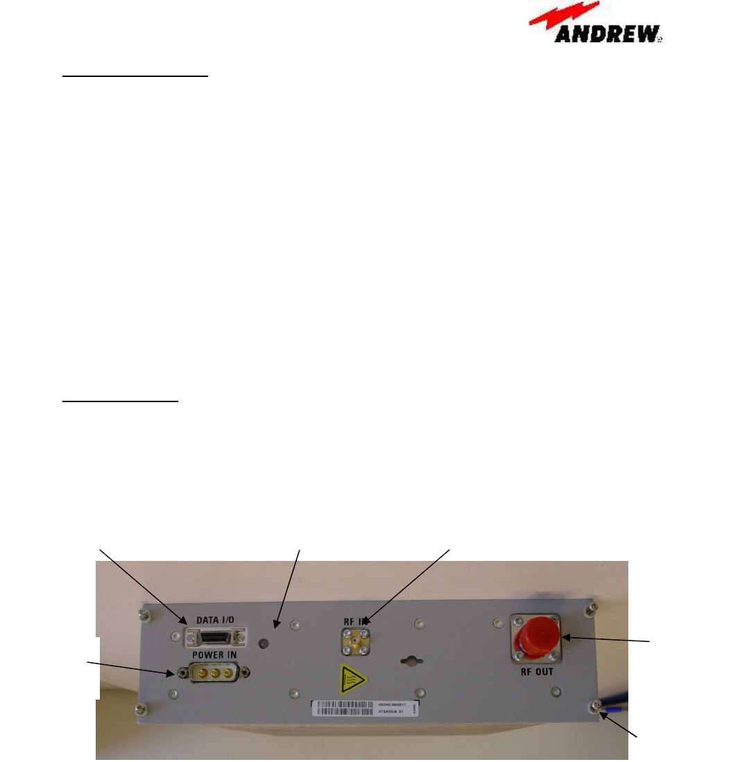
Figure HePA1900 Face plate view
Alarm
LED
RF output
N connector
DC Power
Connector
3W3 D-Sub
Captive Screw
Mounting
Monitoring& control
Multipoint connector RF input
SMA connector
RF Power Amplifiers
Andrew Corporation – Power Amplifier Group
Propriety – Use pursuant to Company Instruction
5 of 5
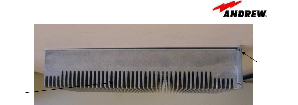
Figure 1 HePA1900 side view
The alarms are mapped to front panel LED behavior, as indicated:
- LED red =major alarm/reset/disable : the PA is not operational
- LED green = the PA is operational = synch present, no alarm, PA ready to
amplify
The amplifier monitoring and control is also managed through a serial link and a
customer specific protocol.
Installation and Operation Set-Up
The HePA1900V3 is easy to operate and use, only requiring a special cables for DC
power and serial bus control connection into the customer frame. RF input and output
connections are done with industry standard SMA and N connectors.
FCC Statements:
FCC ID TBD
This devise complies with Part 2, 15 & 24 of the FCC Rules. Operation is subject to the
following two conditions: (1) this device may not cause harmful interference and (2) this
device must accept any interference received, including interference that may cause
undesired operation.
Warning
Changes of modifications not expressly approved by the manufacturer could void the
user’s authority to operate the equipments.
Heatsink
fins
Captive Screw
Mounting