Andrew Base Station Subsystems Group 100951MCPA Multiple Carrier Power Amplifier MCPA850 RF100951 User Manual Op Instructions Rev
Andrew Corporation, Base Station Subsystems Group Multiple Carrier Power Amplifier MCPA850 RF100951 Op Instructions Rev
Manual

Andrew Wireless Solutions
Propriety – Use pursuant to Company Instruction
1 of 1
Multiple Carrier Power Amplifiers
Model: MCPA850 & MCPA1900
Operation Instruction
Date: April 16, 2008
Version. 2.0
RE: FCC ID S8L-100951MCPA
IC:2237F-100951MCPA,
RE: FCC ID S8L-100963MCPA
IC:2237F-100963MCPA

Andrew Wireless Solutions
Propriety – Use pursuant to Company Instruction
2 of 2
Introduction
This document presents description of the Andrew Corporation 850/1900 Band MCPA
(Multi-Carrier Power Amplifier) amplifiers. The MCPA amplifier is a high power,
mixed-mode RF amplifier intended to provide signal amplification and conditioning. The
MCPA amplifier is compatible with GSM/EDGE and WCDMA air interfaces operating
in U.S. domestic cell sites where FCC compliance is mandatory.
The Cell band (869 MHz to 894 MHz) MCPA and PCS band (1.93 GHz to 1.99 GHz) RF
power amplifier capable of amplifying multiple signals of different modulation types to a
composite power level of 160 Watts.
MCPA Specifications
The MCPA1900and MCPA850 provide linear amplification of multi-carrier, mixed-
mode signals in the cellular and PCS frequency bands, respectively. The 850 Band and
1900 Band MCPA, have the following specifications:
Parameter Specification
Operating RF Band 869-894MHz for 800 Band units
1930-1990MHz for 1900 Band
Instantaneous BW 25MHz for all 800 Band
> 45MHz for all 1900 Band
Rated Output Power
@ ≥ +23.5 to 30 VDC input
160W average for -160 units
(Typical: 40W per Carrier for CDMA /WCDMA and
25W per Carrier for GSM/EDGE/TDMA)
Rated Output Power
@ ≥ +21.0 to < +23.5 VDC 105W average
Input signal types TDMA, GSM/EDGE, WCDMA, CDMA/EVDO
DC power Nominal input voltage is +27VDC
DC voltage input range +21VDC to +30VDC normal
DC-RF Efficiency 18% typical for 160w versions
Physical dimensions 18.5” x 17.25” x 3.75”
Weight 35 pounds, typical
Cooling technique
Integral Fans Front-mounted, full fan tray may be
replaced without PA module removal from sub rack and
without disrupting service.

Andrew Wireless Solutions
Propriety – Use pursuant to Company Instruction
3 of 3
Parameter Specification
Temperature Range -40°C to +50°C operational, -20°C to +50°C meeting
specifications.
Table 1 MCPA Specifications
The cell amplifier has been designed to support an instantaneous bandwidth of 25 MHz.
Multiple carriers may be placed within a continuous 25 MHz span and the product shall
meet specified performance marks. The PCS amplifier has been designed to support an
instantaneous bandwidth of 45 MHz. Multiple carriers may be placed within a
continuous 45 MHz span in the PCS band and the product shall meet specified
performance marks.
Each amplifier has a nominal gain of 56 dB and is phase matched at room temperatures.
The MCPA is designed to track amplitude and phase over all environmental conditions
such that the units may be used in a parallel configuration
Functional Blocks:
The Andrew MCPA is comprised of the following functional areas:
− Preamplifier with unit gain and phase control
− Feed-Forward amplifier circuit
− Main amplifier stage
− Pre-distortion circuit
− FICA (Filter, Isolator, Combiner Assembly)
− Power conversion and conditioning circuit
− Controller circuit
− Communications circuit
Inputs and Outputs:
The amplifier is powered from a DC supply voltage, which can range from 21V to 30V.
The DC power is brought into the amplifier through a D-Sub connector located on the
rear side of the amplifier. The D-Sub connector also contains an RS-485
communications bus.
A second D-Sub connector located on the amplifier front panel is used for RS-232
communication. This connector is only used during factory tests and field maintenance
procedures.
Alarms and operating state are communicated to the outside world through the RS-485
communications bus, the RS-232 communications bus, and visible LEDs located on the
amplifier front panel.

Andrew Wireless Solutions
Propriety – Use pursuant to Company Instruction
4 of 4
The RF signal is brought into the amplifier through a female PkZ type connector located
on the rear of the amplifier. The amplifier RF signal is brought out of the amplifier
through a N type connector located on the rear of the amplifier.
Andrew Wireless Solutions
Propriety – Use pursuant to Company Instruction
5 of 5
Control System:
A microprocessor controller is used to control the amplifier alarm system, control
environmental compensation of the amplifier, and to maintain a linearization solution for
the pre-distortion circuit and the feed-forward circuit.
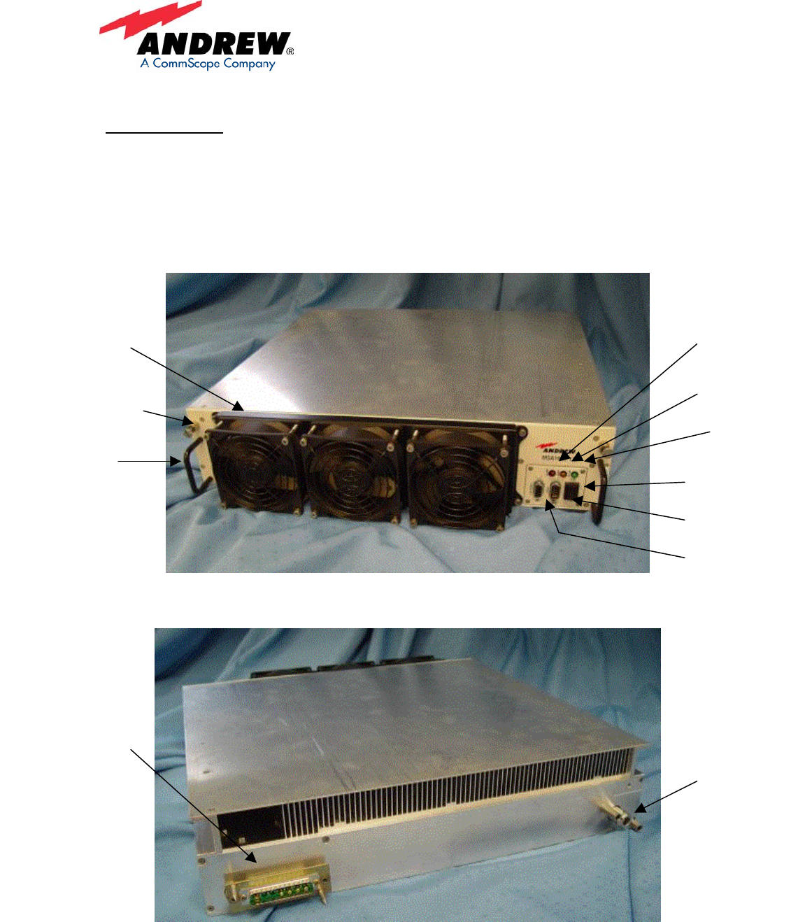
Figure 1 MSA1900-135 MCPA Front Panel
Figure 2 MSA1900-135 Rear Panel
Alarm
LED
Warning
LED
Active
LED
Tx Enable
Disable Switch
RS232 Debug
Port
Fan Tray
Interface
RF Output
Connector
Type N
DC/Control/RF input
Connector
24W7 Combo D-Sub
Captive Screw
Mounting
Handles
Fan Tray
Assembly
Andrew Wireless Solutions
Propriety – Use pursuant to Company Instruction
6 of 6
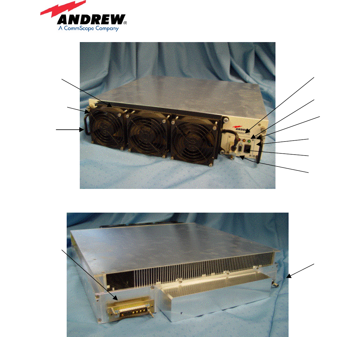
Figure 3 MSA850-135 MCPA Front Panel
Figure 4 MSA850-135 Rear Panel
The following table is a summary of detailed alarms within the PA Module. The alarms
are mapped to front panel LED behavior, as indicated. Additionally, the alarms are
mapped to the discrete line relays and available at the D-Sub connector at the rear of the
PA Module.
Alarm
LED
Warning
LED
Active
LED
Tx Enable
Disable Switch
RS232 Debug
Port
Fan Tray
Interface
Captive Screw
Mounting
Handles
Fan Tray
Assembly
RF Output
Connector
Type N
DC/Control/RF Input
Connector
24W7 Combo D-Sub

Andrew Wireless Solutions
Propriety – Use pursuant to Company Instruction
7 of 7
(Minor Alarms are shown by
Green and Yellow at the same
time)
Condition
(Shading shows
grouping)
Alarm Type
Green LED
Normal
Yellow LED
Major
Red LED
Critical
Comments Retry
Initial Power On, no
alarms
- On On On On for ½ - 1½ secs -
Self Test fail Critical On -
Normal Operation –
RF enabled
- On - - - -
Normal Operation –
RF disabled
- Fast Flash - - 1 Hz complete cycle -
Fans (see note 1) Minor On On - No action
High temp,
Minor
Minor On On - Auto-recover Y
High temp,
Critical (see note 2)
Critical - - On Shut down Y
RF overdrive
Major (see note 3)
Major - On - Gain reduced, Auto-recover Y
RF Overdrive
Critical (see note 4)
Critical - - On Shut down Y
Linearizer (see note
5)
Critical - -- On Shut down -
Device health and
Internal Voltages
Critical - - On Shut down -
Sensor fault (see
note 6)
Critical - - On Shut down -
Device current (see
note 7)
Critical - - On Shut down -
VSWR minor (see
note 8)
Minor On On - No action. 4 sec delay to turn on the LEDs Y
VSWR critical (see
note 9)
Critical - - On Shut down Y
Low input voltage
(<26V)
Major - On - Gain reduced, Auto-recover Y
Bias fault (factory
only) (see note 10)
Critical - - On Shut down -
Self-test fail (see
note 11)
Critical - - On Shut down -
Configuration fault
(EEPROM
checksum)
Critical - - On Shut down -
Table 2 Alarm mapping for PA Module
Note 1: Fan failure is considered a minor alarm since there is no immediate impact on
unit operation, the seriousness depends on ambient temperature, and the high
temperature critical alarm will eventually protect the unit from damage.
Note 2: High temp: will retry when the temperature drops by a hysteresis amount, if
there is no fan alarm.
Note 3: Whenever the overdrive protection mechanism (see above) requires added
attenuation for a sustained period equal to the alarm hysteresis time, an overdrive major
alarm is declared. This condition indicates that firmware has reduced amplifier gain, but
the amplifier output is not being overdriven. This threshold is typically 0.5 dB above
rated output power.
Note 4: This alarm indicates that the input level is of a value which cannot be attenuated
enough by the input attenuator. Shut down must happen fairly quickly (20-100 mS
tentative) to avoid tripping the circuit breakers and to avoid RF device failure. This

Andrew Wireless Solutions
Propriety – Use pursuant to Company Instruction
8 of 8
threshold is typically 10.5 dB above rated input power (51.3 dBm output – 56 dB nominal
gain).
Note 5: Whenever a linearizer alarm occurs, the amplifier is shut down. Each actively
tuned gain and phase adjuster has a factory nominal setting with leash limits around it.
Whenever the tuning algorithm persistently requires an adjustment beyond the leash
limits, a linearizer alarm is declared.
Note 6: Some sensors allow fault detection because they give readings that are out of
range (e.g. temperature sensor).
Note 7: Under current or over current depending on the hardware.
Note 8: Typically 10 dB to set the alarm, with 3 dB of hysteresis (alarm resets at -13 dB).
When operated with other amplifiers in parallel, each amplifier performs its own VSWR
diagnostics and shut down independently. The shutdown process is coordinated with
the RFIM and Switch Combiner Module, eliminating chain reaction scenarios.
Note 9: A VSWR critical alarm is declared when the reflected power is 80W or more and
indicates that the unit may be damaged if not shut down. Since the amplifier cannot
detect that this condition has cleared while shut down, an RF enable command, restart
command, or power cycle is required to clear this condition. Since there are circulators
on the amplifier, a delay of about 1 second is acceptable before shutting down.
Note 10: A bias fault is declared during the factory bias setting algorithm (see above) if
firmware is unable to set the bias correctly. This is typically a hard failure; however, the
bias setting command can be repeated.
Note 11: Self test: Whenever the amplifier is powered on or reset (whether from the front
panel or otherwise), firmware performs a self-test. Included in the test are processor
RAM, boot image checksum, NVM image checksum, temperature sensors, power
supplies, and pilot/receiver operation. If any one of these tests fails, a self-test failure
critical alarm is declared and the unit does not start up. There is no recovery short of a
reset or power cycle. This is typically a hard failure; however, self-test will be repeated
on the next restart command or power cycle.

Andrew Wireless Solutions
Propriety – Use pursuant to Company Instruction
9 of 9
Installation and Operation Set-Up
The MCPA is easy to operate and use, requiring no special cabling since the main
in/put/output and +27V DC @ 30A, power connections are all blind mated into a
backplane. The input signals are also distributed to the amplifiers via the sub rack wiring
from a front RF connector.
FCC Statements:
FCC ID: S8L-100951MCPA & FCC ID S8L-100963MCPA
This devise complies with Part 2, 15,22& 24 of the FCC Rules. Operation is subject to
the following two conditions: (1) this device may not cause harmful interference and (2)
this device must accept any interference received, including interference that may cause
undesired operation.
Warning
Changes of modifications not expressly approved by the manufacturer could void the
user’s authority to operate the equipments.
RF exposure compliance is addressed at the time of licensing, as required by the
responsible FCC Bureau(s), including antenna co-location requirements of 1.1307(b)(3).
Industry Canada Statements:
IC:2237F-100963MCPA & IC:2237F-100951MCPA
1. Quality Norms : The testing of the equipment is carried out as the norms laid in IC
standards.
2. Labeling : MCPA 1900 & MCPA850 when sold in Canada will have:
(a) The certification number, prefixed by the term "IC: ", i.e. IC:2237F-100963MCPA or
IC: 2237F-951MCPA
(b) The manufacturer's name, trade name or brand name, i.e. Andrew Corporation
(c) A model name or number. Model Name = MCPA1900 or MCPA850
Model Number: RF100963 or RF100951
(d) This device complies with RSS-131, RSS-102 of the IC Rules.