Andrew Base Station Subsystems Group OBEMICRO3 OneBase Cell Extender Micro-3 Cabinet User Manual
Andrew Corporation, Base Station Subsystems Group OneBase Cell Extender Micro-3 Cabinet Users Manual
Users Manual
Andrew Corporation
40 Technology Drive
Warren, NJ U.S.A. 07059
Tel: (908) 546-4600
Andrew Wireless Solutions – A Commscope Company
Proprietary – Use Pursuant to Company Instructions
1
SUBJECT: AUTHOR:
OneBase™ Cell Extender Micro-3 Cabinet OBE-1900-M8Y1 Robert Urban
Functional Description 03/06/09
FCC ID: S8L-OBEMICRO3 Version 1.0
Industry Canada ID: 2237F-OBEMICRO3
Overview:
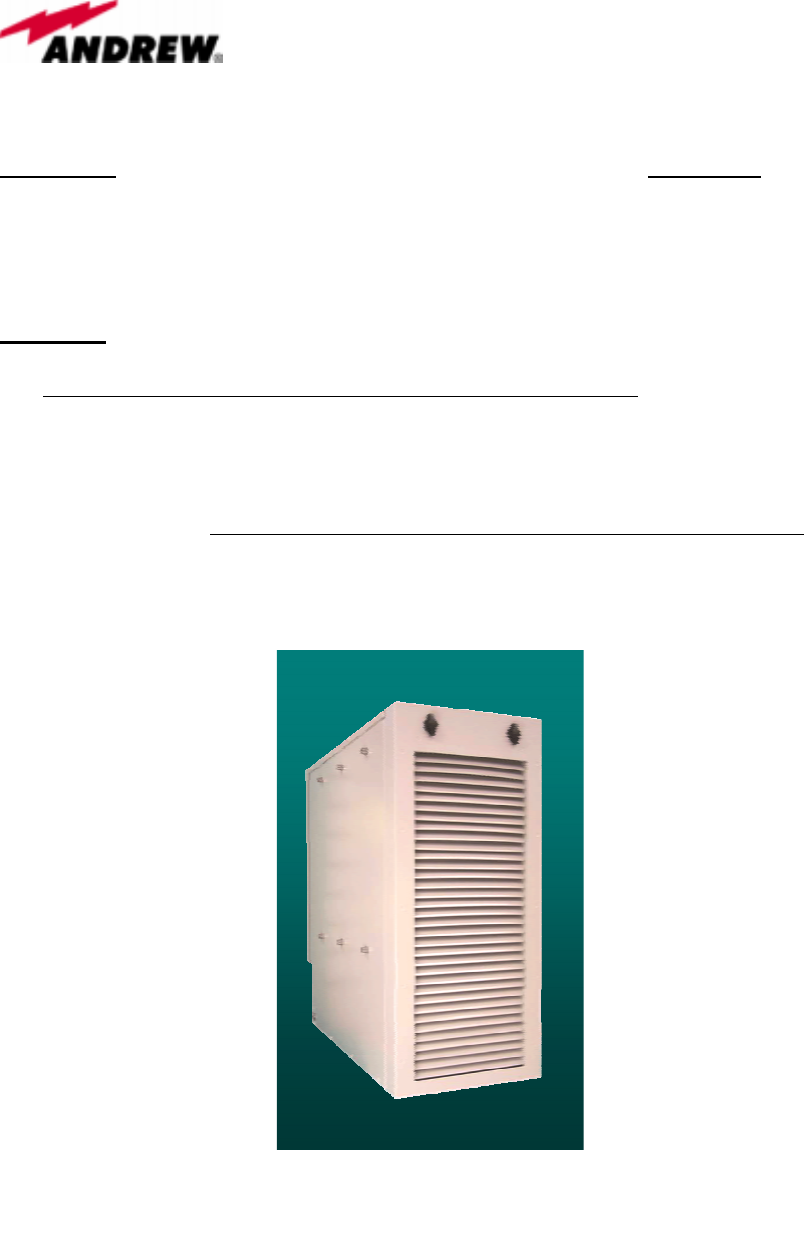
The OneBase™ Cell Extender Micro-3 Cabinet OBE-1900-M8Y1 system is small, self-
contained cabinet unit intended to be used in one, two, or three-sector applications for
cell site signal boosting (Y=1,2,3 represents the number of installed PAs). The system
provides high-power, mixed-mode RF front-end functionality of signal amplification and
conditioning for both uplink and downlink cellular base station signals in the PCS
frequency band. The OneBase™ Cell Extender Micro-3 Cabinet OBE-1900-M8Y1
system can be used for a variety of air interfaces including GSM/EDGE, CDMA, and
WCDMA.
Figure 1: Micro-3 Cabinet
Andrew Corporation
40 Technology Drive
Warren, NJ U.S.A. 07059
Tel: (908) 546-4600
Andrew Wireless Solutions – A Commscope Company
Proprietary – Use Pursuant to Company Instructions
2
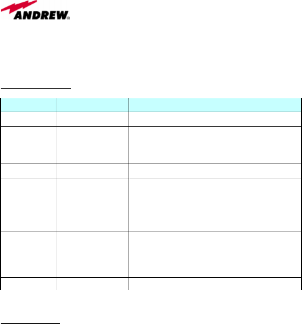
System Specifications:
Parameter Specification Comment
Frequency Band 1900 MHz PCS (Personal Communications Services) Band
Operational
Bandwidth 60 MHz Rx: 1850-1910 MHz
Tx: 1930-1990 MHz
Operating
Temperature -40°C to +50°C Outdoor Application:
Cold start –40°C, Operational spec at –20°C
Output Power 125 Watts System output power utilizing MSA1900-165
Power Draw 4.5 Kilowatts At maximum power output, in overdrive
Supported Output
Power
40 Watts/carrier for
WCDMA or CDMA
25 Watts/carrier for GSM
or EDGE
Typical power-per-carrier at the antenna port.
In-Band emissions -13 dBm/MHz FCC emissions specification
Transmit Path Gain -10 to +15 dB Variable gain adjustment range
Receive Path
Insertion Loss 2.0 dB Typical
Bypass Loss 0.6 dB Maximum
Functional Blocks:
The following system modules are capable of being replaced in the field using common
tools used by field-support personnel. The primary interfaces of the field replaceable
modules are blind-mate type connections or standard cable connections to appropriate
interfaces within the cabinet assembly.
• Multi-carrier Power Amplifier (MCPA) Module
• Input/Output Duplexer (IOD)
• Power Subsystem: Rectifier Module, Breaker Tray, Fuse Block
• Bypass Switch Module (BSM)
• Fan Tray Subsystem: Fans and Fan Controller
• RF Interface Module (RFIM)
Andrew Corporation
40 Technology Drive
Warren, NJ U.S.A. 07059
Tel: (908) 546-4600
Andrew Wireless Solutions – A Commscope Company
Proprietary – Use Pursuant to Company Instructions
3
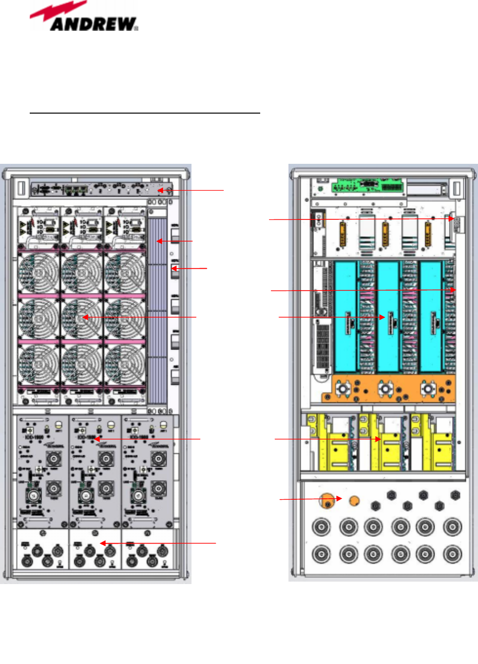
Functional Block Diagram & Cabinet Layout:
For Functional Block Diagram: Refer to “Functional Description”.
MCPA Modules (3)
IOD Modules (3)
BSM (3)
Rectifier Modules (4)
RFIM
Breaker Tray
Fan Controller
Front
Rear
Hatch Plate
(interface to BTS
and AC)
Fuse Block
Cabinet doors and Fan Tray not shown
Figure 2: Micro-3 Cabinet Layout

Andrew Corporation
40 Technology Drive
Warren, NJ U.S.A. 07059
Tel: (908) 546-4600
Andrew Wireless Solutions – A Commscope Company
Proprietary – Use Pursuant to Company Instructions
4
Alarms:
The OneBase™ Cell Extender Micro-3 Cabinet OBE-1900-M8Y1 system characterizes
alarm severity according the following table.
ALARM
CATEGORY SEVERITY
Minor Conditions that do not immediately affect system operation, but lead to more
serious problems if ignored (e.g. fan failure).
Major Conditions that directly affect amplifier operation (e.g. reduced gain), but allow the
system to continue operating.
Critical Conditions which result in sector shutdown, preventing any further cellular call
traffic.
MCPA LEDs:
The MCPA module has three (3) LED indicators on the front panel and labeled as
follows:
o “ALARM” (Red)
o “WARNING” (Yellow)
o “ACTIVE” (Green)
The following chart summarizes the various LED conditions, alarm severity, and possible
failure modes.

Andrew Corporation
40 Technology Drive
Warren, NJ U.S.A. 07059
Tel: (908) 546-4600
Andrew Wireless Solutions – A Commscope Company
Proprietary – Use Pursuant to Company Instructions
5
MCPA LEDs
MCPA LEDs Status Alarm Severity Possible Failure Modes
Green: “ON”
Yellow: “ON”
Red: “ON”
Initial Power-up
of MCPA.
NONE
LEDs all “ON” simultaneously for about 2 seconds.
Green: “ON” Normal
Operation NONE
Green: “ON”
Yellow: “ON”
Minor
1. MCPA high internal temperature (approximately
between 80°C and 90°C).
2. MCPA values on “Micro MCPA Live Display”
software indicating:
--Poor Return Loss (3-8 dB)
--Poor VSWR (2.32 - 5.85)
Yellow: “ON” Major
1. RF Overdrive (gain reduced)
2. DC voltage out of normal range
Red: “ON” Critical
1. MCPA internal failure
2. RF Overdrive (> 10 dB)
3. MCPA high internal temperature
(above approximately 90°C).
4. MCPA values on “Micro MCPA Live Display”
software indicating:
--Poor Return Loss (0-3 dB)
--Poor VSWR (above 5.85)

Andrew Corporation
40 Technology Drive
Warren, NJ U.S.A. 07059
Tel: (908) 546-4600
Andrew Wireless Solutions – A Commscope Company
Proprietary – Use Pursuant to Company Instructions
6
Fan Controller LEDs:
Fan Controller Board
LED Status Alarm
Severity Possible Failure Modes
LED 1, 4: GREEN No indication NONE / Disabled
LED 2, 3, 5, 6: GREEN Normal
Operation
LED 2: RED Thermistor shorted or open.
LED 3: RED Fan #3 failed.
LED 5: RED Fan #1 failed.
LED 6: RED Fan #2 failed.
Dry Contact Summary Alarms:
ALARM Possible Failure Modes
Door Alarm Intrusion
Fan Alarm
1. Fan controller loses power.
2. Fan is spinning at less than 1900 RPM.
3. Thermistor shorted or open, resulting in no valid thermistor output.
4. Blocked fan rotor.
Rectifier Alarm Rectifier failure
Minor MPCA Minor Failure: See “Table 10”, user defined mapping of Door,
Fan, or Rectifier alarms to Minor.
Major MPCA Major Failure: See “Table 10”, user defined mapping of Door,
Fan, or Rectifier alarms to Major.
Critical MPCA Critical Failure: See “Table 10”, user defined mapping of Door,
Fan, or Rectifier alarms to Critical.

Andrew Corporation
40 Technology Drive
Warren, NJ U.S.A. 07059
Tel: (908) 546-4600
Andrew Wireless Solutions – A Commscope Company
Proprietary – Use Pursuant to Company Instructions
7
Installation and Operation Set-Up
The OneBase™ Cell Extender Micro-3 Cabinet OBE-1900-M8Y1 is shipped from the
factory with all necessary internal cables and wiring. Each unit is factory tested to meet
overall product requirements. As such, installation of the Micro-3 Cabinet involves the
mounting and securing of the cabinet per detailed manual instructions. Power is supplied
to the unit via terminal blocks located in the rear of the cabinet behind the fan tray
assembly. BTS and Antenna port interfacing is provided on the rear patch panel, with
labeled 7/16 DIN connectors.
FCC Statements: FCC ID: S8L-OBEMICRO3
This device complies with Part 2, 15 and 24 of the FCC Rules. Operation is subject to the
following two conditions: (1) this device may not cause harmful interference and (2) this
device must accept any interference received, including interference that may cause
undesired operation.
Warning
Changes of modifications not expressly approved by the manufacturer could void the
user’s authority to operate the equipment.
RF exposure compliance is addressed at the time of licensing, as required by the
responsible FCC Bureau(s), including antenna co-location requirements of 1.1307(b)(3).
Industry Canada Statements: IC:2237F-OBEMICRO3
1. Quality Norms : The testing of the equipment is carried out as the norms laid in IC
standards.
2. Labeling : OneBase™ Cell Extender Micro-3 Cabinet OBE-1900-M8Y1 when
sold in Canada will have:
(a) The certification number, prefixed by the term "IC: ", i.e. IC:2237F-OBEMICRO3
(b) The manufacturer's name, trade name or brand name, i.e. Andrew Corporation
(c) A model name or number. Model Name = OneBase™ Cell Extender Micro-3
Cabinet Model Number: OBE-1900-M8Y1 (Y=1,2,3 represents the number of installed PAs)
(d) This device complies with RSS-131, RSS-102 of the IC Rules.
3. External Control
The OneBase™ MicroCabinet Cell Extender OBE-1900-M8Y1 does not have any
external controls accessible to the user for any adjustments, to operate in violation of the
limits prescribed in this Standard. Furthermore, information on internal adjustments,

Andrew Corporation
40 Technology Drive
Warren, NJ U.S.A. 07059
Tel: (908) 546-4600
Andrew Wireless Solutions – A Commscope Company
Proprietary – Use Pursuant to Company Instructions
8
reconfiguration or programmability of the device shall only be made available to service
depots and agents of the equipment supplier and NOT to the public.
4. Exposure of Humans to RF Field : The equipment conforms to RSS-102. RF
Exposure compliance is also addressed at the time of licensing.
5. Multi-carrier operation : Rated output power of the equipment is for multi-carrier
operation, which is 125 Watts maximum total composite. For multiple carriers, the total
output power is distributed as required for each RF carrier. The rating per carrier is
reduced so the total output power is not exceeded. While there is a possibility of single-
carrier use, the maximum output power shall still not exceed 125 Watts. In fact, typical
usage for various carriers is usually no greater than 40 Watts per carrier (see
Specification table).