Andrew Wireless Innovations Group BCP-TFAM26 Model TFAM26 Downlink Booster User Manual
Andrew Wireless Innovations Group Model TFAM26 Downlink Booster
Contents
- 1. Users manual part 1 of 3
- 2. Users manual part 2 of 3
- 3. Users manual part 3 of 3
Users manual part 3 of 3
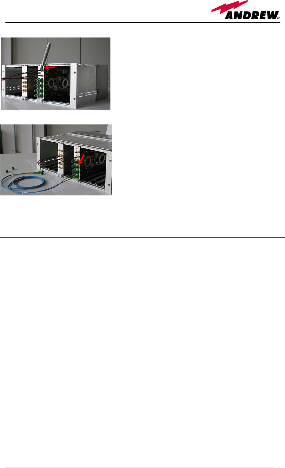
Then connect the UL and the DL RF cable (which come
from a TBSI or a TLCN module, depending on how the
system has been designed) to the TFLN UL and DL
ports, respectively.
Use a specific torque wrench to fix these RF cables to
DL and UL ports.
Remove the caps from TFLN optical ports and connect the
SC-APC fibre optic cables to the ports.
UL and DL cables coming from the same remote unit have
to be connected to UL and DL ports marked by the same
number on the TFLN front panel.
As you switch on the system, carefully refer to the TFLN Start-Up section.
Remember that remote units should be switched on before than the Master Unit in order to follow a
correct Start-Up procedure.
TFLN behaviour at system start-up
Before the Master Unit is switched on, make sure that:
• all expected modules have been inserted into the Master Unit
• the modules have been connected each other by RF jumpers, according to what planned in the
system design
• every TFLN local unit has been connected to relevant remote units
• each remote unit has been connected to its coverage antennas
• the supervision agent, if present, has been connected to the Master Unit
• different Master Units are connected each other via bus RS485
After that, remember that only when all the remote units are already on, the Master Unit itself can be
turned on.
Once the Master Unit has been switched on, the TFLN behaviour at system start-up can be summarized
as per the following steps:
1. When Master Unit is turned on all the six LEDs upon the TFLN front panel go on for a couple
of seconds. After that, the green LED remains on (indicating proper power supply) while the
other LEDs indicate the local unit status, according to the following table.
Note: In case unused optical ports of the TFLN have not been masked through LMT yet,
corresponding LEDs will be on. If so, wait for the end of step 3 (discovery phase) then use
LMT to mask them (please refer to relevant Application Note)
51
MN024-04

Label LED colour Status
= Green ON
(power supply is on)
┌┘ Red OFF
(no major failure affects TFLN operations)
1 Red OFF
(no major failure affects corresponding remote unit or UL
connection)
2 Red OFF
(no major failure affects corresponding remote unit or UL
connection)
3 Red OFF
(no major failure affects corresponding remote unit or UL
connection)
4 Red OFF
(no major failure affects corresponding remote unit or UL
connection)
Tab. 11: Status of the TFLN LEDs in full-working conditions
2. About 10 seconds after the system has been switched on, TFLN module begins a “discovery”
phase to identify connected remote units. This operation is necessary to collect all the
information to be provided to the supervision system.
While the discovery phase is working, the TFLN general alarm (LED ┌┘) blinks while the
other LEDs go on showing previously detected status. Time dedicated to discovery phase can
be at maximum 4min and depends on system complexity. Do not connect/disconnect any
cable or any piece of equipment during the discovery phase! This may result in failing the
identification of remote units.
Please note that, while the discovery phase is running, the whole system is working correctly.
Discovery operations aim to collect information about remote units but they don’t affect the
system functionality.
3. Once the discovery is finished, the TFLN general alarm (LED ┌┘) stops blinking and switches
OFF. The power supply LED (green LED) remains on while LEDs 1,2,3,4 show either the
status of the remote units or the quality of the UL connections. In case some of these LEDs
remain on, check if they refer to unused optical ports or not. In case of unused TFLN ports use
LMT to mask it otherwise if LED referring to a connected remote unit remains on, please refer
to Troubleshooting procedure.
Removing a TFLN module
Switch off the Master Unit power supply, remove the SC-APC optical connectors, and insert the
protection caps into TFLN optical ports. Then
• unscrew the 4 screws and slowly remove the card.
• put the removed TFLN card in its safety box.
• switch on again the Master Unit power supply, and refer to Start Up section.
52 User Manual

TFLN troubleshooting
In case a TFLN local unit has any problem, this will be easily revealed through LEDs on TFLN front
panels.
Troubleshooting procedure can be easy when failure detection is directly carried out through LMT or
supervision system, as an alternative, a manual troubleshooting procedure can be carried out.
LEDs panel on TFLN front detect not only failures inside the TFLN, but they also reveals malfunctions
located on related remote unit.
The following table reports a brief description of the TFLN alarms, together with a reference to the
corresponding alerted LEDs:
Tab. 12: TFLN LEDs description
As the table shows, LEDs on the TFLN front panel signal all high priority alarms while minor alarms,
which detect critical situations which should be checked and tested in order to avoid future possible
system faults, are only revealed by LMT or supervision system.
Each TFLN is provided with an AGC system which compensates optical losses < 3 dB. TFLN LED
alarms switch on when the estimated optical losses are > 4dB, the AGC not being able to compensate
these losses any more.
One of LEDs 1,2,3,4 might turn on not only to indicate a high optical loss detected by TFLN, but also to
reveal a remote unit failure. Understanding the reason why one of LEDs 1,2,3 or 4 is on (a remote unit
failure, an optical cable fault or an external equipment malfunction) can be done following the
troubleshooting procedure reported hereinafter.
Alarm description
Alerted
LED
Alarm
priority level
The optical power received on UL port 1 is too low and the AGC can
no more compensate the optical losses on UL port 1 1 High
The optical power received on UL port 2 is too low and the AGC can
no more compensate the optical losses on UL port 2 2 High
The optical power received on UL port 3 is too low and the AGC can
no more compensate the optical losses on UL port 3 3 High
The optical power received on UL port 4 is too low and the AGC can
no more compensate the optical losses on UL port 4 4 High
The optical power received on UL port 1,2,3, or 4 is near to critical level
but AGC still works none Low
High priority alarm on Remote Unit 1 1 High
High priority alarm on Remote Unit 2 2 High
High priority alarm on Remote Unit 3 3 High
High priority alarm on Remote Unit 4 4 High
Low priority alarm on Remote Units 1, 2, 3 or 4 none Low
TFLN laser failure ┌┘ High
UL RF amplifier failure ┌┘ High
DL RF amplifier failure ┌┘ High
Short circuit on TFLN module ┌┘ High
Overtemperature on TFLN board1 none Low
1 Remember that proper TFLN environmental temperature is between +5°C and +40°C
53
MN024-04

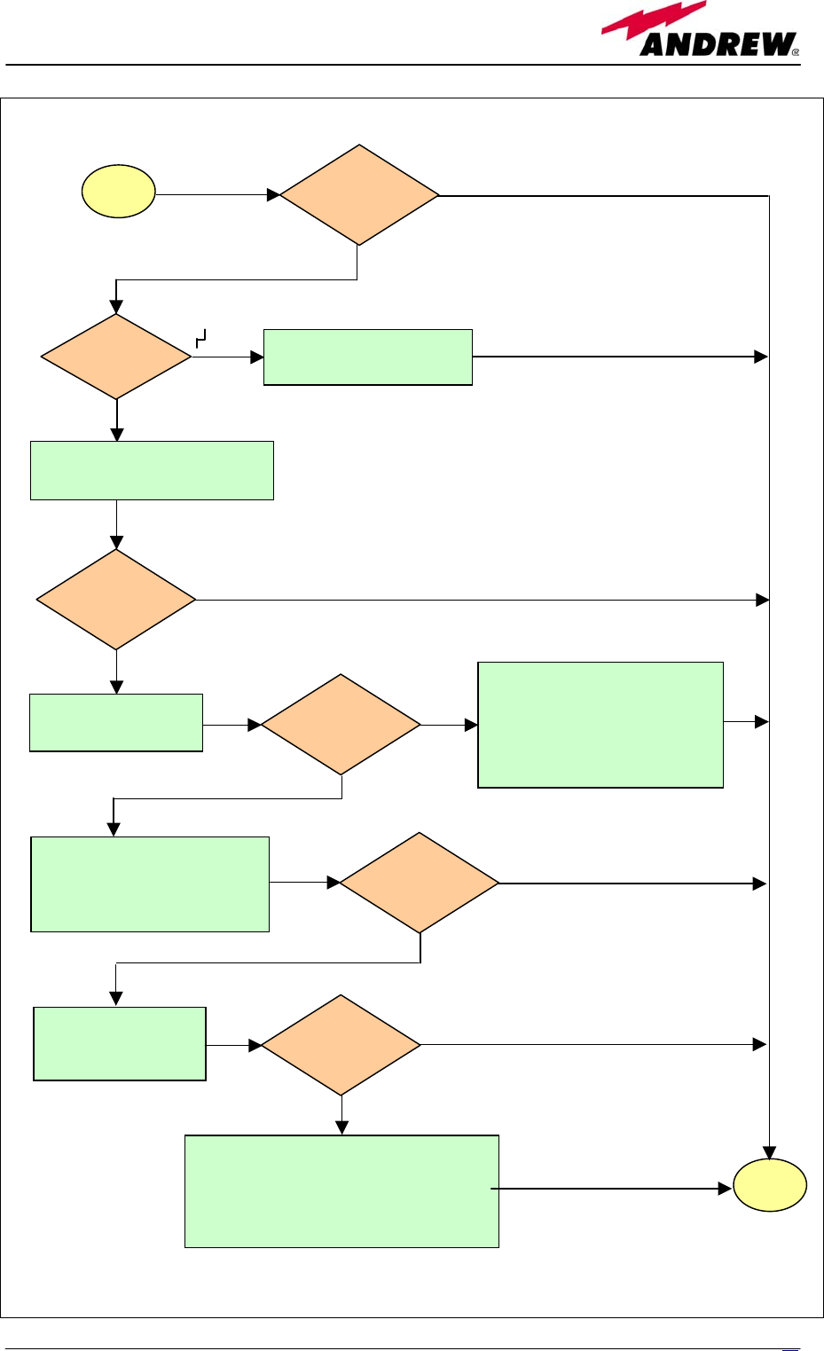
Main troubleshooting procedure
(The following procedure is summarized by the flow-chart in fig. 21)
In case the TFLN general alarm (LED ┌┘) is on replace the faulty TFLN local unit with a new one
and contact the manufacturer for assistance.
In case one of the LEDs 1,2,3,4 is on the corresponding TFLN adapter might be dirty. Try cleaning
it using pure ethyl alcohol. If the LED is still on go to the corresponding remote unit side and check
the red LED upon TFAxxx warm side:
If it is off, the optical cables or the optical connections are supposed to have some problem
on DL path. Refer to fibre optic DL troubleshooting for more information (fig. 22).
If it is on, refer to dry-contact troubleshooting (fig. 10) to understand whether the alarm can
depend on external equipment failure or not. In case dry-contact troubleshooting does not
reveal any failure, clean the remote unit optical adapters.
If the problem still persists the UL optical cable or optical connections is supposed to have
some problems. Please refer to the fibre optic UL troubleshooting (fig. 11) for more
information.
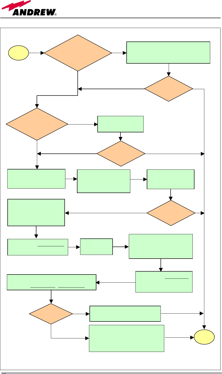
Fibre optic DL troubleshooting
(The following procedure is summarized by the flow-chart in fig. 22)
Check if there is any point where fibre experiences a short radius of curvature. In this case,
rearrange the optical path in order to avoid sharp bends (if necessary, replace the optical cable with
a longer one). If TFLN red LED switches off, troubleshooting has been successfully carried out.
Otherwise, follow next steps.
Check if SC-APC connectors are properly installed at both fibre ends. In case they are not, fix
better SC-SPC connectors to adapters. If TFLN red LED switches off, troubleshooting has been
successful. Otherwise, follow next steps.
Disconnect the optical fibre and clean it better at both ends then clean the SC-APC ports on both
the TFLN and the remote unit. Re-connect the fibre to relevant ports after cleaning. If it doesn’t
made TFLN red LED switch off, follow next steps.
Disconnect the optical SC-APC connector from remote unit DL port, and measure the output power
Pout(DL) at the corresponding fibre end. Then, go to the TFLN side, disconnect the optical SC-APC
connector from TFLN DL port and measure the input power Pin(DL) coming out of the TFLN DL
port. Calculate the DL fibre attenuation ADL as ADL [dB] = P in(DL) - P out(DL)
If ADL > 4dB, then the fibre optic cable has some problems. Replace it with a new one.
If ADL < 4dB troubleshooting procedure has not identified the problem. Refer to supervision
system or contact assistance.
54 User Manual
Is red LED
upon TFLN
still ON?
end
Clean the SC-APC
optical adapters an
d
connectors
Yes
No
start
Which red
LED is ON?
1, 2, 3 or 4
Replace the faulty TFLN
Clean corresponding SC-APC
optical adapter and connector
Yes
Is any red LED
ON upon the
TFLN?
N
o
Go to corresponding
remote unit side
Verify if any external equipmen
t
or dry contact port has some
problems Refer to the dry-
contact troubleshooting (fig. 10)
N
o
Yes
DL optical cables or optical
connections are supposed to
have some problems. Refer to
fibre optic DL troubleshooting
(fig. 22)
N
o
UL optical cable or optical connections
are supposed to have some problems.
Refer to fibre optic UL troubleshooting
(fig. 11)
N
o
Yes
Is red LED
upon remote
unit ON?
Is red LED
upon remote
unit still ON?
Is red LED
upon remote
unit still ON?
Fig. 21: Flow-chart describing the main troubleshooting procedure
5
5
MN024-04
Go to TFLN
side.
Is red LED
upon remote
unit still ON?
Is red LED
upon remote
unit still ON?
Y
es
No
Y
es
N
o
end
Troubleshooting procedure has
not identified the problem. Refe
r
to supervision system or contac
t
assistance
Fibre optic cable has some
problems. Replace it.
Is ADL > 4dB?
Calculate DL fibre attenuation
ADL[dB]=input power - output power
Disconnect optical SC-APC
connector from TFLN DL
port.
Measure the input powe
r
coming out of the TFLN
DL port.
Measure the output powe
r
at corresponding fibre end.
Reconnect the fibre
to relevant ports
Disconnect fibre optic
and clean it at both ends.
Clean optical SC-APC
p
orts on both TFLN
and remote unit.
Disconnect the optical
SC-APC connector fro
m
remote unit DL port
Y
es
N
o
Y
es
No
Y
es
N
o
N
o
Yes
Fix better SC-APC
connectors
Are SC-APC
connectors properly
installed at both fibre
ends?
Is red LED
upon remote
unit still ON?
Rearrange the optical path to avoid
sharp bends. If necessary replace the
optical cable with a longer one.
Is there any
point where the
fibre experiences
a small radius of
curvature?
start
Fig. 22: Flow-chart describing the fibre optic DL troubleshooting
5
6
User Manual

4.3. 2-way splitter TLCN2
5
7
MN024-04
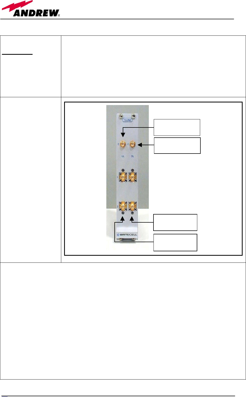
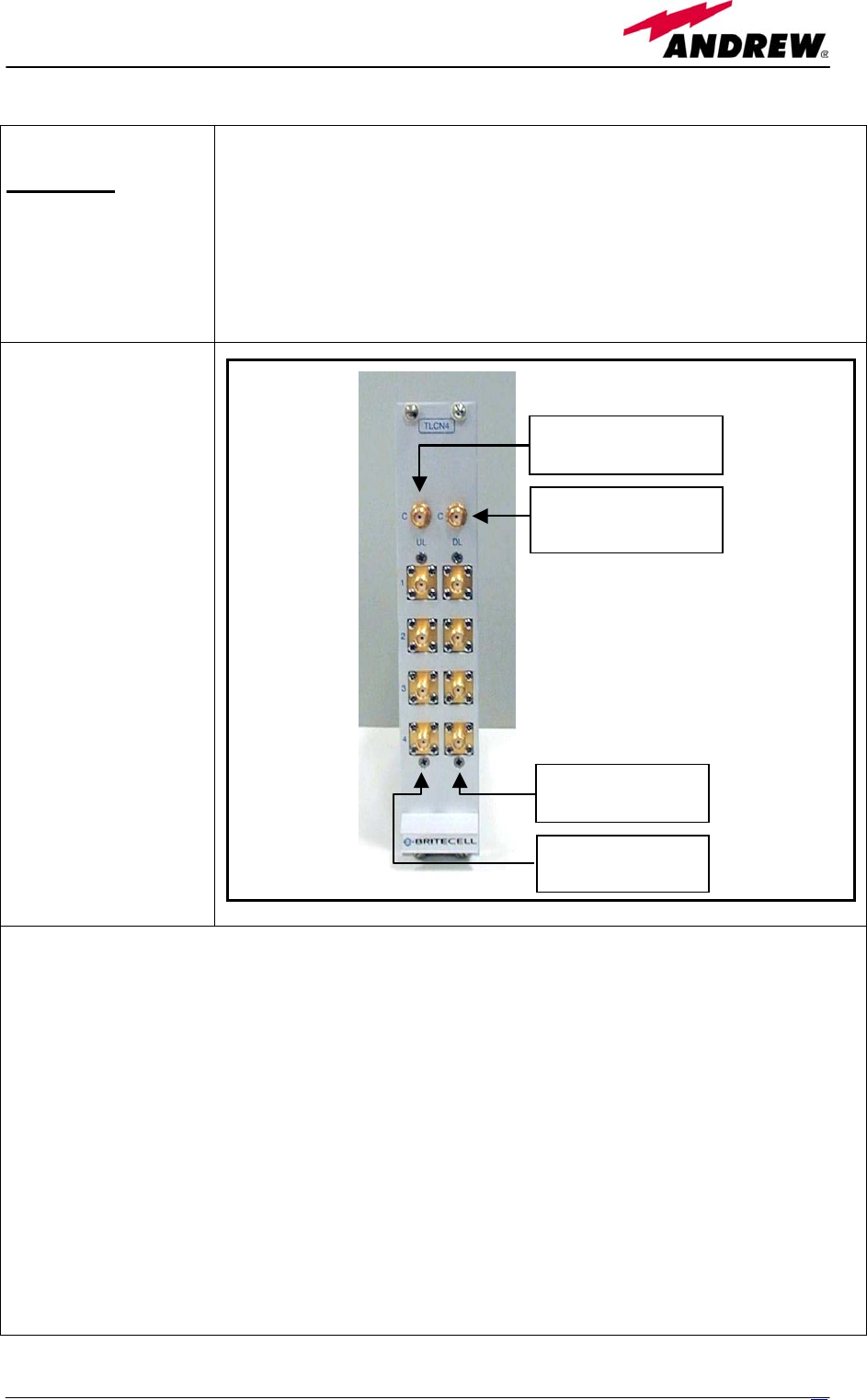
Module name:
TLCN2
Description:
The TLCN2, bidirectional 2-way splitter/combiner, can be used to:
combine 2 RF signals into a common RF output
split an RF input into 2 RF output signals
It is a passive device which doesn’t require power supply.
In case of splitting “C” works as an input port while “1” and “2” ports are the
outputs. In case of combining “1”and “2” work as input ports while “C” is the
output one.
RF ports:
1 DL common RF
port (“C”)
2 DL splitted RF
ports (“1”,“2”)
1 UL common RF
port (”C”)
2 UL splitted RF
ports (“1”,“2”)
Note: each port is
bidirectional.
TLCN2 main applications
Main applications of the TLCN2 module are:
• Connecting a BTS to more than one TFLN local unit, so that:
TLCN2 splits the DL input coming from a BTS into 2 output signals entering 2 different
TFLN local units
TLCN2 combines the UL inputs coming from 2 TFLN local units into 1 common signal,
entering the BTS
• Connecting a TFLN local unit to more than one BTS, so that:
TLCN2 combines the two DL inputs coming from 2 BTSs into 1 output signal entering the
TFLN local unit
TLCN2 splits the UL inputs coming from TFLN local unit into 2 different output signals
entering 2 different BTSs
More TLCN2 modules can be used in cascade connections.
DL common RF
p
ort
(
SM
A
-f
)
UL common RF
port (SMA-f)
UL splitted RF
ports (SMA-f)
DL splitted RF
ports (SMA-f)
58 User Manual

TLCN2 insertion loss
The TLCN2 insertion loss varies slightly with the frequency bands:
When designing the system, remember to take into account the insertion loss of the TLCN2.
700-1400MHz 1400-2200MHz 2200-2500MHz
TLCN2 insertion loss 3.7 ± 0.4dB 4.1 ± 0.5dB 4.6 ± 0.4dB
Warnings
The overall input power must not exceed +24dBm
TLCN2 Installation
Since the TLCN2 module requires no power supply it can be housed either in an active or a passive
TPRN subrack.
1. Unpack the kit which include
1 TLCN2
4 RF jumpers
2. Carefully insert the TLCN2 module in any of the TPRN subrack slots and lock the 4 screws on the
front corners.
3. Connect RF cables to UL and DL ports, according to what planned by designer. Use a specific torque
wrench to fix each cable to relevant ports.
4. In case some ports remain unused remember to connect them to a 50 Ω load (not included)
59
MN024-04

4.4. 4-way splitter TLCN4
6
0
User Manual
Module name:
TLCN4
Description:
The TLCN4, bidirectional 4-way splitter/combiner, can be used to:
combine 4 RF signals into a common RF output
split an RF input into 4 RF output signals
It is a passive device which doesn’t require power supply.
In case of splitting “C” works as an input port while “1”, “2”, “3” and “4”
ports are the outputs. In case of combining “1”, “2”, “3” and “4” work as input
ports while “C” is the output one.
RF ports:
1 DL common RF
port (“C”)
4 DL splitted RF
ports
(“1”,“2”,“3”,“4”)
1 UL common RF
port (”C”)
4 UL splitted RF
ports
(“1”,“2”,“3”,“4”)
Note: each port is
bidirectional.
TLCN4 main applications
Main applications of the TLCN4 module are:
• Connecting a BTS to more than one TFLN local unit, so that:
TLCN4 splits the DL input coming from a BTS into 4 output signals entering 4 different
TFLN local units
TLCN4 combines the UL inputs coming from 4 TFLN local units into 1 common signal,
entering the BTS
• Connecting a TFLN local unit to more than one BTS, so that:
TLCN4 combines the two DL inputs coming from 4 BTSs into 1 output signal entering the
TFLN local unit
TLCN4 splits the UL inputs coming from TFLN local unit into 4 different output signals
entering 4 different BTSs
More TLCN4 modules can be used in cascade connections.
A-f)
-f)
UL splitted RF
p
orts
(
SM
A
-f
)
DL splitted RF
ports (SMA-f)
UL common RF
port (SM
DL common RF
port (SMA
61
MN024-04

TLCN4 insertion loss
The TLCN4 insertion loss varies slightly with the frequency bands:
When designing the system, remember to take into account the insertion loss of the TLCN2.
700-1400MHz 1400-2200MHz 2200-2500MHz
TLCN4 insertion loss 7.4 ± 0.4dB 8.0 ± 0.5dB 8.4 ± 0.4dB
Warnings
The overall input power must not exceed +24dBm
TLCN4 Installation
Since the TLCN4 module requires no power supply it can be housed either in an active or a passive
TPRN subrack.
1. Unpack the kit which include
1 TLCN4
8 RF jumpers
2. Carefully insert the TLCN4 module in any of the TPRN subrack slots and lock the 4 screws on the
front corners.
3. Connect RF cables to UL and DL ports, according to what planned by designer. Use a specific
torque wrench to fix each cable to relevant ports.
4. In case some ports remain unused remember to connect them to a 50 Ω load (not included)
62 User Manual

4.5. RF diplexer TLDN
63
MN024-04
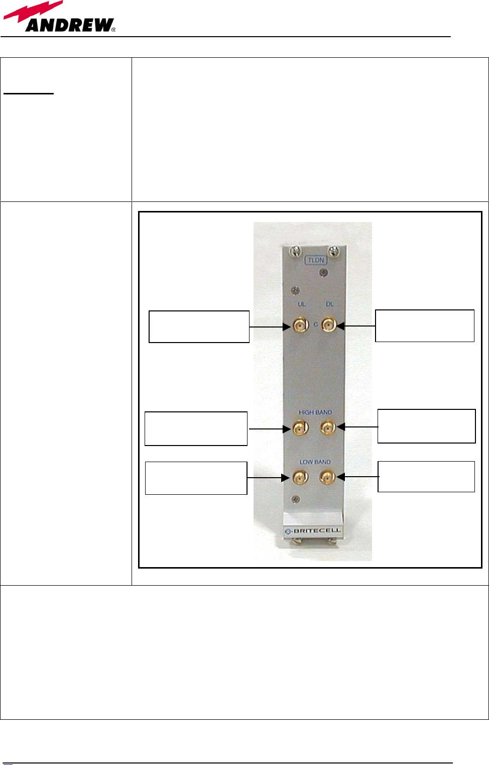
Module name:
TLDN
Description:
The TLDN is a passive RF diplexer which combine/split low-band (800-
1000MHz) and high-band (1700-2200MHz) signals in a multi-band system.
Main operations carried out are:
In Downlink it combines a low band RF signal (800MHz to 1000MHz)
and a high band RF signal (1700MHz to 2200MHz) into a common RF
path
In UpLink it splits a composite signal into a low-band (800MHz to
1000MHz) and a high-band (1700MHz to 2200MHz) one.
As it is a passive device it doesn’t need power supply.
RF ports
1 DL common RF port
(“C”), which sends out
the combined DL signal
1 DL high-band RF
input port, which
receives the high-band
signal
1 DL low-band RF
input port, which
receives the low-band
signal
1 UL common RF port
(“C”), which receives
the combined UL signal
1 UL high-band RF
output port, which
sends out the high-band
signal
1 UL low-band RF
output port, which
sends out the low-band
signal
TLDN main applications
Main applications of the TLDN module are:
• Connecting 2 BTSs with different services to one TFLN local unit in a dual band system, so that:
TLDN combines the DL inputs coming from 2 different BTSs (carrying different services) into
an output signal entering a TFLN local unit
TLDN divides the UL input coming from a TFLN local unit into 2 UL outputs entering 2
different BTSs (carrying different services)
DL common RF
port (SMA-f)
DL high-band RF
port (SMA-f)
DL low-band RF
p
ort
(
SM
A
-f
)
UL high-band RF
port (SMA-f)
UL low-band RF
port (SMA-f)
UL common RF
port (SMA-f)
64 User Manual

TLDN insertion loss
The TLDN insertion loss is as follows:
When designing the system, remember to take into account the insertion loss of the TLDN.
TLDN insertion loss <1.5dB
Warnings
The overall input power must not exceed +27dBm
TLDN Installation
Since the TLDN module requires no power supply it can be housed either in an active or a passive
TPRN subrack.
1. Unpack the kit which include
1 TLDN
4 RF jumpers
2. Carefully insert the TLDN module in any of the TPRN subrack slots and lock the 4 screws on the
front corners.
3. Connect RF cables to UL and DL ports, according to what planned by designer. Use a specific
torque wrench to fix each cable to relevant ports.
6
5
MN024-04

4.6. RF triplexer TLTN
6
6
User Manual
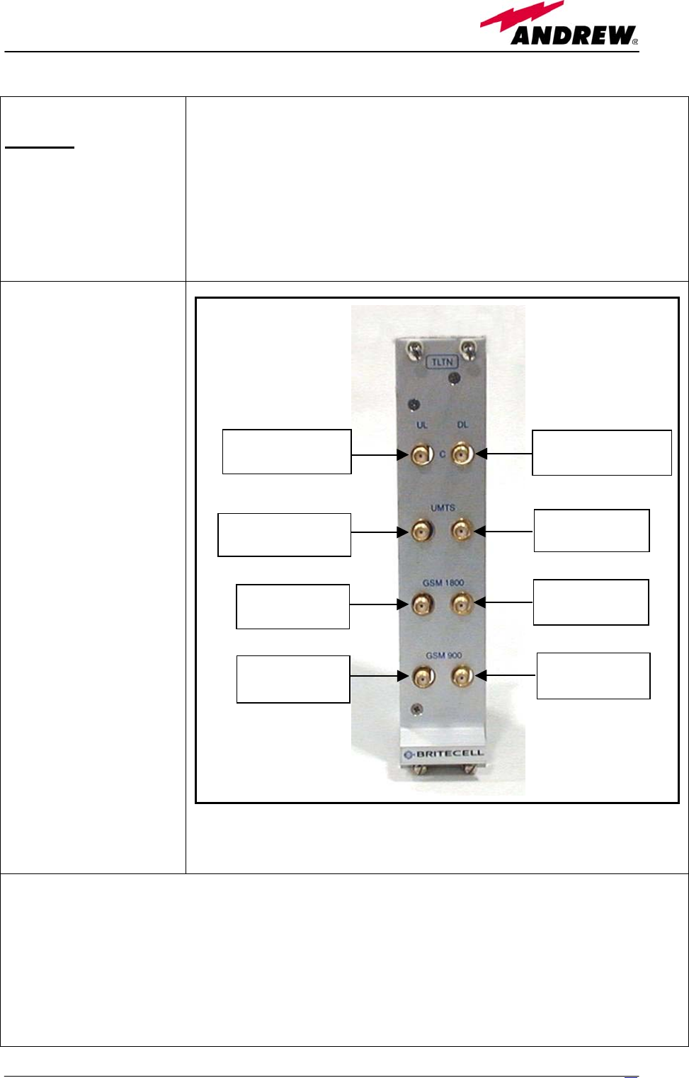
Module name:
TLTN
Description:
The TLTN is a passive RF triplexer which combine/split low-band (800-
1000MHz), GSM1800 and UMTS signals in a multi-band system.
Main operations carried out are:
In Downlink it combines a low band RF signal (800MHz to 1000MHz)
a GSM1800 signal and an UMTS signal into a common RF path
In UpLink it splits a composite signal into a low-band (800MHz to
1000MHz) a GSM1800 and an UMTS one.
As it is a passive device it doesn’t need power supply.
RF ports
1 DL common RF port
(“C”), which sends out
the combined DL signal
1 DL UMTS RF input
port, which receives the
UMTS band signal
1 DL GSM1800 RF
input port, which
receives the GSM1800
signal
1 DL low band RF
input port, which
receives the low band
signal
1 UL common port
(“C”), which receives
the combined UL signal
1 UL UMTS RF output
port, which sends out
the UMTS signal
1 UL GSM1800 RF
output port. which
sends out the GSM
1800 signal
1 UL low band RF
output port, which
sends out the low band
signal
TLTN main applications
Main applications of the TLTN module are:
• Connecting 3 BTSs with different services to one TFLN local unit in a tri-band system, so that:
TLTN combines the DL inputs coming from 3 different BTSs (carrying different services: low
band, GSM1800 and UMTS) into an output signal entering a TFLN local unit
TLTN divides the UL input coming from a TFLN local unit into 3 UL outputs entering 3
different BTSs (carrying different services: low band, GSM1800 and UMTS)
DL common RF
port (SMA-f)
DL GSM1800
port (SMA-f)
DL low band
port (SMA-f)
UL GSM1800
port (SMA-f)
UL low band
port (SMA-f)
UL common RF
port (SMA-f)
DL UMTS port
(
SM
A
-f
)
DL UMTS port
(
SM
A
-f
)
6
7
MN024-04

TLTN insertion loss
The TLTN insertion loss is as follows:
When designing the system, remember to take into account the insertion loss of the TLDN.
TLTN insertion loss <3.5dB
Warnings
The overall input power must not exceed +27dBm
TLTN Installation
Since the TLTN module requires no power supply it can be housed either in an active or a passive TPRN
subrack.
1. Unpack the kit which include
1 TLTN
6 RF jumpers
2. Carefully insert the TLTN module in any of the TPRN subrack slots and lock the 4 screws on the front
corners.
3. Connect RF cables to UL and DL ports, according to what planned by designer. Use a specific torque
wrench to fix each cable to relevant ports.
6
8
User Manual

4.7. RF duplexer THYN
69
MN024-04
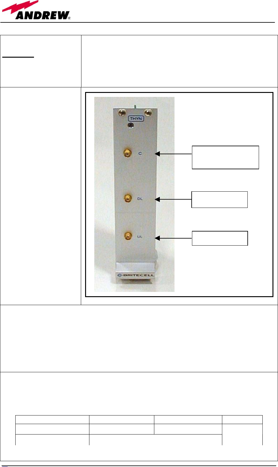
Module name:
THYN
Description:
THYN is a family of duplexers which combines/splits the downlink
and uplink paths into a single one while maintaining the required
isolation. As this device is band dependent be sure to choose the right
single band version.
RF ports
1 DL port, which
receives DL signal
1 UL port, which sends
out the UL signal
1 common port (“C”),
which provides an UL
and DL combined
signal
THYN main applications
Main applications of the THYN module are:
• Connecting a BTSs with duplexed antenna port to a Britecell Plus system, so that:
THYN combines/splits the DL and UL signals coming from a single port of the BTS into
two separated ports
THYN insertion loss
The THYN insertion loss is as follows:
Frequencies < 1GHz Frequencies > 1 GHz UMTS
THYN UL insertion loss 7.0 ± 1dB 7.0 ± 1.5dB
THYN DL insertion loss 3.3 ± 0.5dB 2.0 ± 0.5dB
When designing the system, remember to take into account the insertion loss of the TLDN.
RF port combining
UL and DL signals
UL RF port
DL RF port
7
0
User Manual

Warnings
The overall input power must not exceed +30dBm
THYN Installation
Since the THYN module requires no power supply it can be housed either in an active or a passive
TPRN subrack.
1. Unpack the kit which include
1 THYN
2 RF jumpers
2. Carefully insert the THYN module in any of the TPRN subrack slots and lock the 4 screws on the
front corners.
3. Connect RF cables to common, UL and DL ports, according to what planned by designer. Use a
specific torque wrench to fix each cable to relevant ports.
71
MN024-04

4.8. RF attenuator TBSI
72 User Manual
Module name:
TBSI
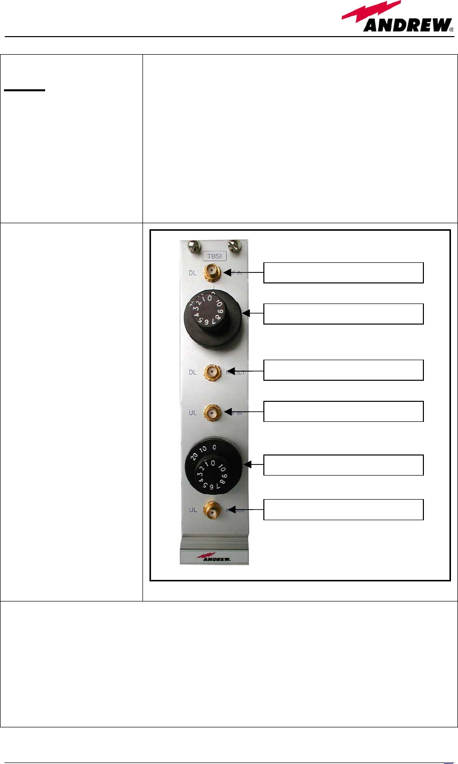
Description
The TBSI module is an adjustable RF attenuator, necessary in order
to:
set the correct power level for the RF downlink signal
entering the DL input port of the TFLN local unit;
set the correct power level for the RF uplink signal entering
the BTS, in order to meet desired requirements about BTS
blocking level and BTS receiver sensitivity
In order to set these different attenuations TBSI provides 2 separate
knobs to regulate UL and DL attenuations independently (please
refer to BriteTool manual to understand how to calculate the right
value of attenuation trough BriteTool)
RF ports
1 DL RF input port
receiving the DL signal to
be attenuated
1 DL RF output port
sending out the attenuated
DL signal
1 UL RF input port
receiving the UL signal to
be attenuated
1 UL RF output port
sending out the attenuated
UL signal
The attenuation required both
on DL and UL can be
properly set through relevant
knob (30dB range, 1dB step).
TBSI main applications
Main applications of the TBSI module are:
• adjusting RF levels coming to/from a BTSs:
TBSI adjusts the DL signal to meet the required power level at TFLN DL input
TBSI adjusts the UL signal coming from TFLN to provide the required blocking level
and receiver sensitivity to the BTS
Downlink RF input (from BTS)
Downlink attenuation knob
Downlink RF output (to TFLN)
Uplink RF input (from TFLN)
Uplink attenuation knob
Uplink RF output (to BTS)
73
MN024-04

TBSI insertion loss
The TBSI insertion loss is as follows:
DC to 2GHz 2GHz to 2.17GHz
TBSI insertion loss < 1dB < 1.3dB
When designing the system, remember to take into account the insertion loss of the TBSI.
Warnings
The overall input power must not exceed +30dBm
TBSI Installation
Since the TBSI module requires no power supply it can be housed either in an active or a passive
TPRN subrack.
1. Unpack the kit which include
1 TBSI
2 RF jumpers
2. Carefully insert the TBSI module in any of the TPRN subrack slots and lock the 4 screws on the
front corners.
3. Connect RF cables according to what planned by designer. Use a specific torque wrench to fix
each cable to relevant ports.
4. Set proper attenuation values.
74 User Manual

4.9. Digital RF attenuator TDI
7
5
MN024-04
Module name:
TDI
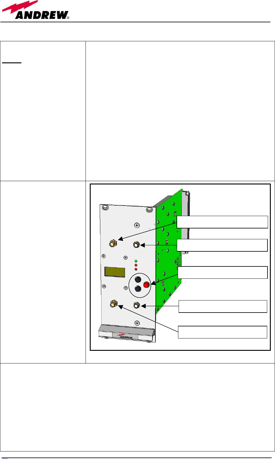
Description
The TDI module is a digital adjustable RF attenuator, necessary in
order to:
set the correct power level for the RF downlink signal
entering the DL input port of the TFLN local unit;
set the correct power level for the RF uplink signal entering
the BTS, in order to meet desired requirements about BTS
blocking level and BTS receiver sensitivity. In UL apart from
the 30dB attenuation range, it is provided with a gain allowing
increasing dynamic available for the optimisation of the
performances at BTS side.
Being digital, the TDI is provided with a LCD panel and buttons
allowing setting the different attenuations on UL and DL
independently (please refer to BriteTool manual to understand how to
calculate the right value of attenuation trough BriteTool). The
attenuation settings can also be done remotely through the
supervision system.
RF ports
1 DL RF input port
receiving the DL signal to
be attenuated
1 DL RF output port
sending out the attenuated
DL signal
1 UL RF input port
receiving the UL signal to
be attenuated
1 UL RF output port
sending out the attenuated
UL signal
The attenuation required both
on DL and UL can be
properly set through LCD
display or supervision system
(30dB range, 1dB step).
TDI main applications
Main applications of the TDI module are:
• adjusting RF levels coming to/from a BTSs:
TBSI adjusts the DL signal to meet the required power level at TFLN DL input
TBSI adjusts the UL signal coming from TFLN to provide the required blocking level
and receiver sensitivity to the BTS
It is advisable to use this module when an increase of the dynamic available on the UL path is
needed.
Downlink RF input (from BTS)
Uplink RF input (from TFLN)
Attenuation setting buttons
Downlink RF output (to TFLN)
Uplink RF output (to BTS)
7
6
User Manual

TDI visual alarms
The TDI front panel is provided
with 2 LEDs showing status and
alarm information.
LED meaning is reported on the
rightward table.
Further information about alarm
status is delivered by Britecell
Plus supervision system.
The Temperature alarm is considered a minor alarm and as the
policy is to show through LED signalling only the major alarm, it
will be provided only by the supervision system.
In case of power supply degradation the green LED switch off and
the problem is signalled through the supervision system.
Label LED colour Meaning
Power Green Power supply status OK
UL Alarm Red UL amplifier failure
TDI power supply
Each TDI digital attenuator is supplied by the subrack back-plane (+12V).
The power consumption of each TDI is 3W max.
Warnings
The overall input power must not exceed +30dBm
Inserting or removing TDI modules
• Do not remove or insert any TDI module into TPRN subrack before having switched off main
power supply.
• The TDI modules must be handled with care, in order to avoid damage to electrostatic sensitive
devices.
TDI Installation
The TDI digital attenuator is housed in a TPRN subrack and its dimensions are 19” width and 4HE
height. A TDI module can be accommodated in any of these 12 slots.
Note: In case a new TDI module has to be installed in a still working Master Unit, switch off the
subrack before inserting the plug-in TDI module
1. Unpack the kit which include
1 TDI
2 RF jumpers
2. Carefully insert the TDI module in any of the TPRN subrack slots and lock the 4 screws on the
front corners.
3. Connect RF cables according to what planned by designer. Use a specific torque wrench to fix
each cable to relevant ports.
4. Switch on the subrack and set proper attenuation values.
Tab. 13: Summary of TDI LEDs meaning
7
7
MN024-04

Removing a TDI module
Switch off the Master Unit power supply and remove RF jumpers. Then
• unscrew the 4 screws and slowly remove the card.
• put the removed TDI card in its safety box.
• switch on again the Master Unit power supply.
7
8
User Manual

4.10. Power limiter TMPx-10
79
MN024-04
Module name:
TMPx-10
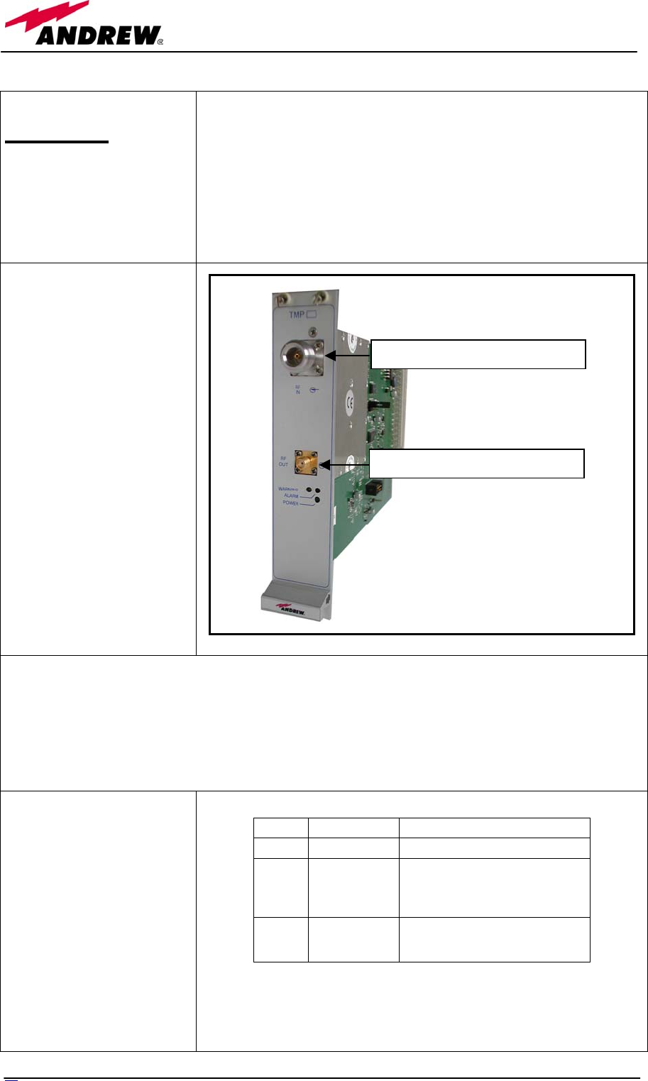
Description
TMPx-10 power limiter is available in two versions, one suitable for
2G services and the other for 3G.
This module monitors the DL input power and when Operator’s BTS
power increases above a set threshold, it ensures the signal path being
attenuated by 10dB to avoid subsequent circuits being overdriven.
TMPx-10 threshold is programmable through the supervision system.
RF ports
1 DL RF input port
receiving the DL signal to
be checked from the BTS
1 DL RF output port
sending out the DL signal
TMP main applications
Main applications of the TMP module are:
• Check DL RF level coming from a BTS in order to protect the system if the level exceed a
programmed threshold
TMP visual alarms
The TMP front panel is
provided with 3 LEDs
showing status and alarm
information.
LED meaning is reported on
the rightward table.
Further information about
alarm status is delivered by
Britecell Plus supervision
system.
Label LED colour Meaning
Power Green Power supply status OK
Warning
Amber
It signals a general warning which
can be due to:
- over temperature
- no RF signal at input port
Alarm
Red
General TMP failure, it can be:
- power supply degradation
- switched mode active (10dB att.)
Tab. 14: Summary of TMP LEDs meaning
Downlink RF output
Downlink RF input (from BTS)
8
0
User Manual

TMP power supply
Each TMPx-10 power limiter is supplied by the subrack back-plane (+12V).
The power consumption of each TMPx-10 is 2W max.
TMP insertion loss
The TMP insertion loss is as follows:
TMP insertion loss < 1.5dB
When designing the system, remember to take into account the insertion loss of the TMP.
Warnings
The overall input power must not exceed +35dBm
Inserting or removing TMP modules
• Do not remove or insert any TMP module into TPRN subrack before having switched off main
power supply.
• The TMP modules must be handled with care, in order to avoid damage to electrostatic sensitive
devices.
TMP installation
The TMP power limiter is housed in a TPRN subrack and its dimensions are 19” width and 4HE
height. A TMP module can be accommodated in any of these 12 slots.
Note: In case a new TMP module has to be installed in a still working Master Unit, switch off the
subrack before inserting the plug-in TMP module
1. Unpack the kit which include
1 TMP
1 RF jumper
2. Carefully insert the TMP module in any of the TPRN subrack slots and lock the 4 screws on the
front corners.
3. Connect RF cables according to what planned by designer. Use a specific torque wrench to fix
each cable to relevant ports.
4. Switch on the subrack
Removing a TMP module
Switch off the Master Unit power supply and remove RF jumpers. Then
• unscrew the 4 screws and slowly remove the card.
• put the removed TMP card in its safety box.
• switch on again the Master Unit power supply.
81
MN024-04

5. Optional equipment
and accessories
82 User Manual

5.1. WLAN interface TWLI
83
MN024-04
Module name:
TWLI
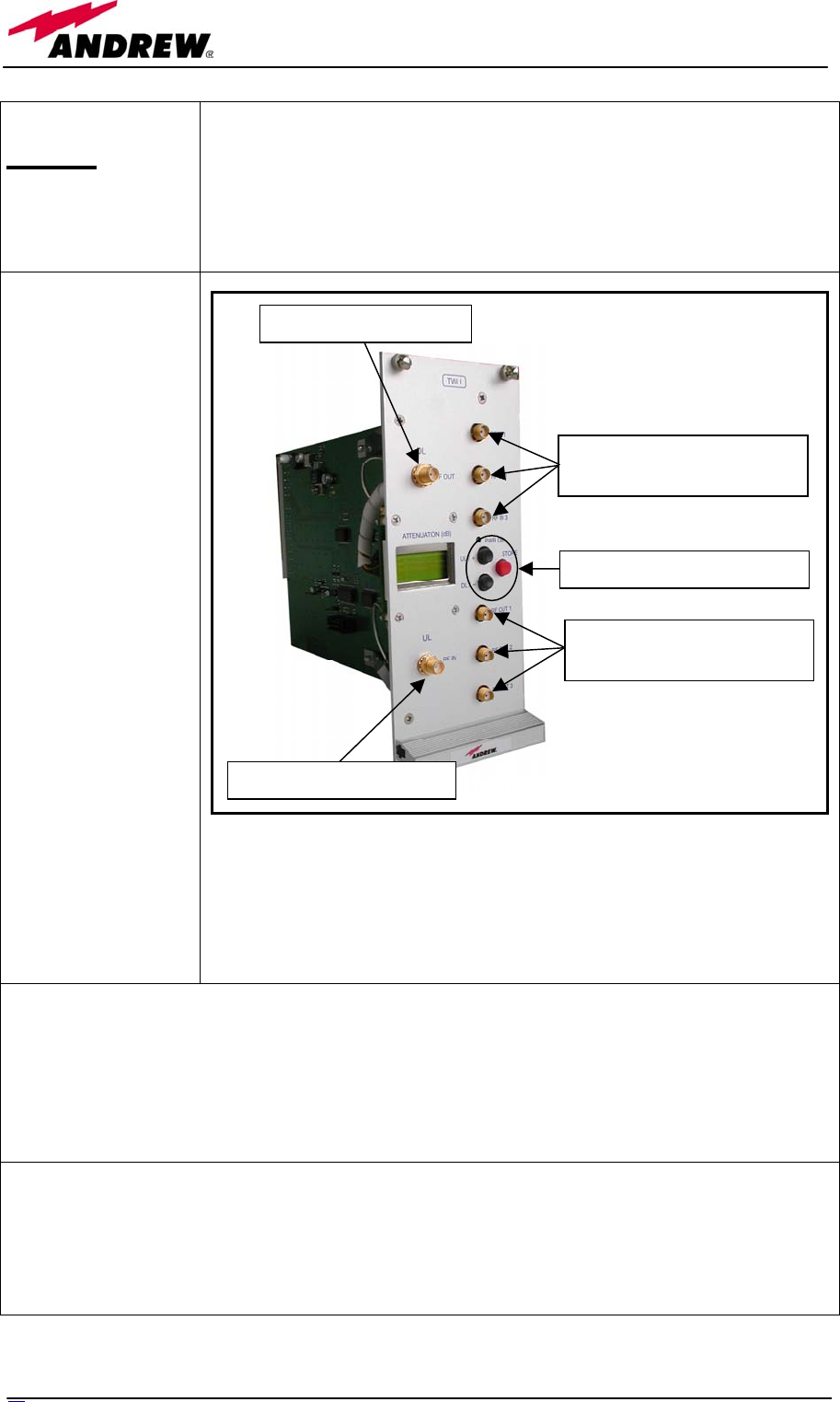
Description
Britecell Plus system allows distributing WLAN service (802.11b) through
an auxiliary channel while concentrating all the Access Points together with
the central equipment.
The TWLI module allows connecting up to 3 Access Points to one TFLN
and setting up to 4dB attenuation, if needed, on the DL path.
RF ports
3 DL RF input
ports receiving the
DL signals from up
to 3 different
Access Points
1 DL RF output
port sending out
the DL signal to the
TFLN auxiliary
port
1 UL RF input port
receiving the UL
signal from the
TFLN auxiliary
port
3 UL RF output
ports sending out
the UL signals to
up to 3 different
Access Points
A 4dB attenuation
range is available on
the DL path in order to
adjust levels coming
from the Access
Points.
TWLI main applications
Main applications of the TWLI module are:
• provide to the TFLN the WLAN signals coming from up to 3 Access Points concentrated on the
same room.
TWLI power supply
Each TWLI WLAN interface module is supplied by the subrack back-plane (+12V).
The power consumption of each TWLI is 2W max.
DL RF input
from Access Points 1 to 3
Attenuation setting buttons
DL RF output to TFLN
UL RF input from TFLN
UL RF output
to Access Points 1 to 3
84 User Manual

Warnings
The overall input power must not exceed +19dBm
Inserting or removing TWLI modules
• Do not remove or insert any TWLI module into TPRN subrack before having switched off main
power supply.
• The TWLI modules must be handled with care, in order to avoid damage to electrostatic sensitive
devices.
TWLI installation
The TWLI WLAN interface is housed in a TPRN subrack and its dimensions are 19” width and 4HE
height. A TWLI module can be accommodated in any of these 12 slots.
Note: In case a new TWLI module has to be installed in a still working Master Unit, switch off the
subrack before inserting the plug-in TWLI module
1. Unpack the kit which include
1 TWLI
2 RF jumpers
2. Carefully insert the TWLI module in any of the TPRN subrack slots and lock the 4 screws on the
front corners.
3. Connect RF cables according to what planned by designer. Use a specific torque wrench to fix
each cable to relevant ports.
4. Switch on the subrack
Removing a TWLI module
Switch off the Master Unit power supply and remove RF jumpers. Then
• unscrew the 4 screws and slowly remove the card.
• put the removed TWLI card in its safety box.
• switch on again the Master Unit power supply.
8
5
MN024-04

5.2. Amplifier TWANx
8
6
User Manual
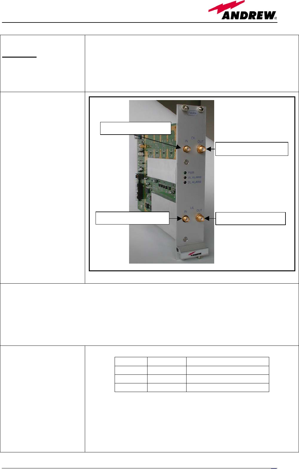
Module name:
TWAN
Description
The purpose of the TWAN module is to amplify DL and UL signals when
Britecell Plus is interfaced with a low power BTS.
The gain allows also compensating for losses in splitting/combining network.
As this device is band dependent be sure to choose the right single band
version.
RF ports
1 DL RF input port
receiving the DL signal
from BTS
1 DL RF output port
sending out the amplified
DL signal to the TFLN
1 UL RF input port
receiving the UL signal
from TFLN
1 UL RF output port
sending out the amplified
UL signal to the BTS
TWAN main applications
Main applications of the TWAN module are:
• amplifying the levels to/from a low power BTS:
• compensate for splitting/combining network losses
TWAN visual alarms
The TWAN front panel is
provided with 3 LEDs
showing status and alarm
information.
LED meaning is reported on
the rightward table.
Further information about
alarm status is delivered by
Britecell Plus supervision
system.
The Temperature alarm is considered a minor alarm and as the policy is to
show through LED signalling only the major alarm, it will be provided only
by the supervision system.
In case of power supply degradation the green LED switch off and the
problem is signalled through the supervision system.
Label LED colour Meaning
Power Green Power supply status OK
UL Alarm Red UL amplifier failure
DL Alarm Red DL amplifier failure
Tab. 15: Summary of TWAN LEDs meaning
UL RF output to BTS
UL RF input from TFLN
DL RF input from BTS
DL RF output to TFLN
8
7
MN024-04

TWAN power supply
Each TWAN digital attenuator is supplied by the subrack back-plane (+12V).
The power consumption of each TWAN module is 3W max.
Warnings
The overall input power must not exceed 0dBm
Inserting or removing TWAN modules
• Do not remove or insert any TWAN module into TPRN subrack before having switched off main power
supply.
• The TWAN modules must be handled with care, in order to avoid damage to electrostatic sensitive
devices.
TWAN Installation
The TWAN digital attenuator is housed in a TPRN subrack and its dimensions are 19” width and 4HE
height. A TWAN module can be accommodated in any of these 12 slots.
Note: In case a new TWAN module has to be installed in a still working Master Unit, switch off the subrack
before inserting the plug-in TWAN module
1. Unpack the kit which include
1 TWAN
2 RF jumpers
2. Carefully insert the TWAN module in any of the TPRN subrack slots and lock the 4 screws on the front
corners.
3. Connect RF cables according to what planned by designer. Use a specific torque wrench to fix each
cable to relevant ports.
4. Switch on the subrack.
Removing a TWAN module
Switch off the Master Unit power supply and remove RF jumpers. Then
• unscrew the 4 screws and slowly remove the card.
• put the removed TWAN card in its safety box.
• switch on again the Master Unit power supply.
8
8
User Manual

5.3. WLAN booster TFBWx
89
MN024-04
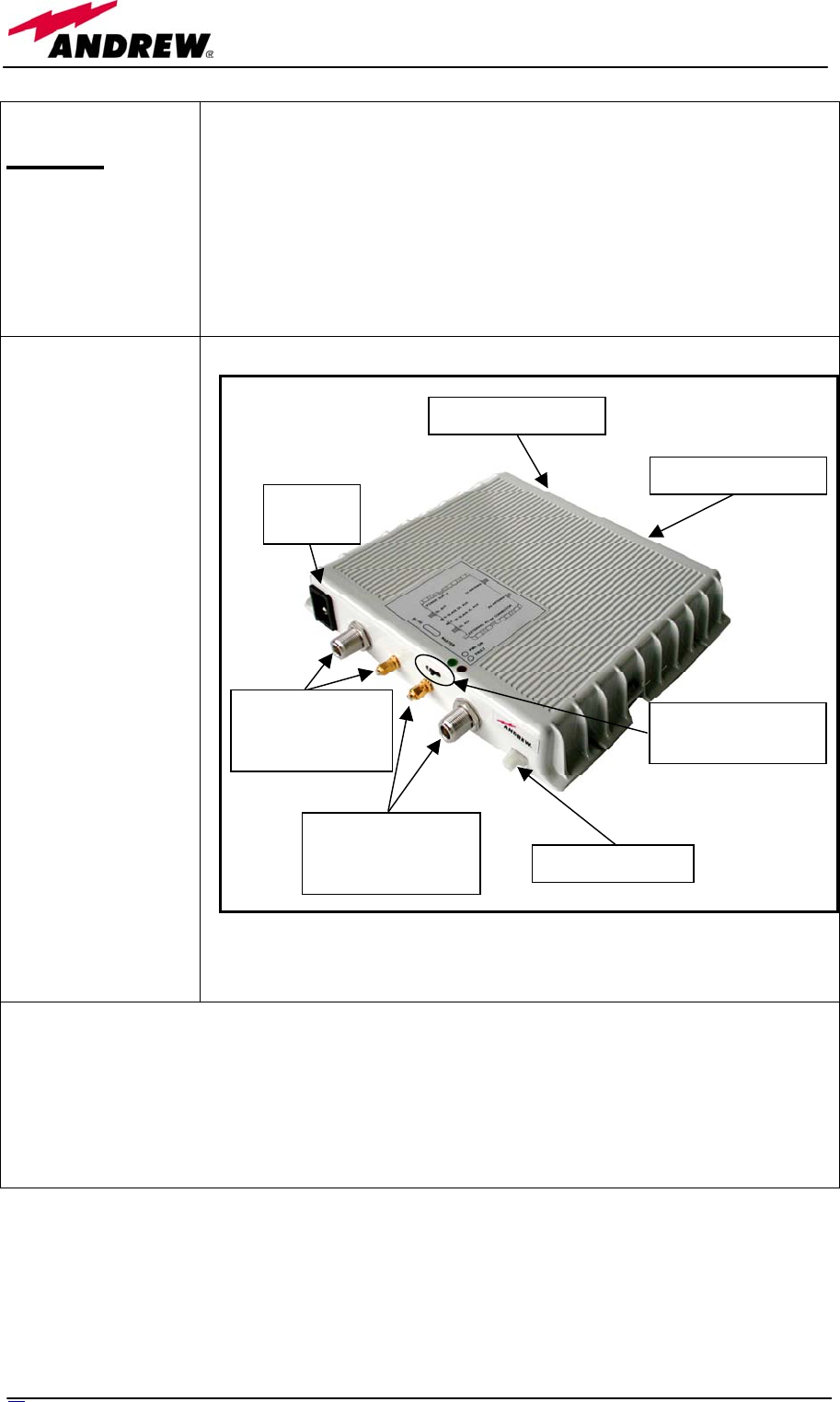
Module name:
TFBW
Description
Britecell Plus system allows distributing WLAN service (802.11b) through
an auxiliary channel while concentrating all the Access Points together with
the central equipment.
The TFBW radio front end is connected to the remote unit in order to
provide the radio coverage through the antennas (one for TX and the other
for RX, required isolation between these antennas is 50dB). Up to 2 TFBW
boosters can be cascaded to provide two coverage points.
RF ports
1 DL RF AUX
input port receiving
the DL signal from
TFLN
1 DL RF AUX
output port sending
out the DL signal
to another TFBW
slave
1 TX antenna port
1 UL RF AUX
input port receiving
the UL signal from
another TFBW
slave
1 UL RF AUX
output port sending
out the UL signal
to the TFLN
1 RX antenna port
A MASTER/SLAVE
selector is provided
allowing connecting
two cascaded boosters
TFBW main applications
Main applications of the TFBW module are:
• amplify UL and DL WLAN signals coming to/from the auxiliary channel of a TFLN
• provide WLAN coverage through a TX and a RX antenna
TX antenna (N-f)
RX antenna (N-f)
Power
supply
DL AUX
from TFLN (N-f)
to slave (sma-f)
UL AUX
from slave (sma-f)
to TFLN (N-f) alarm connector
MASTER/SLAVE
selector
9
0
User Manual
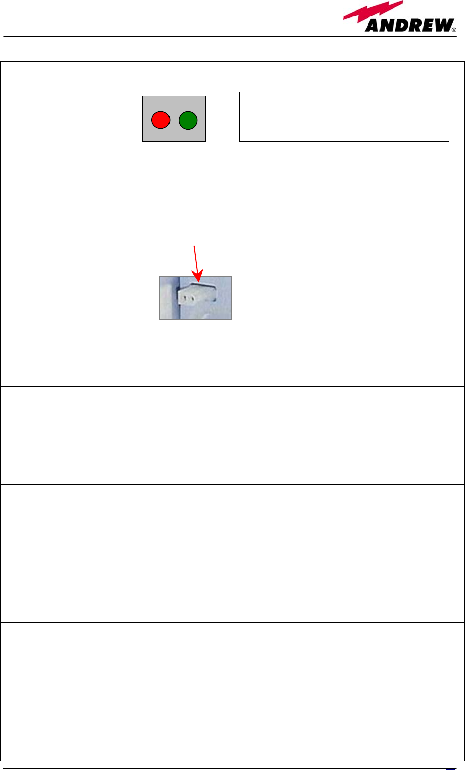
Visual alarms:
Two control LEDs are
provided on the TFBW
front side.
The green LED describes
the power supply status,
while the red LED
describes the major booster
failures.
Dry contact alarms:
TFBW is provided with a
dry contact output, which
can be connected to any of
the dry contacts available
on the remote unit. In such
a way, the alarm
information about this
external device can be
signalled through the red
LED of remote unit.
Led colour Meaning
Red DL amplifier failure
Green Power supply status OK
Power supply:
TFBW WLAN booster can be powered by universal mains (85/265 Vac) or by negative supply (-72/-
36 Vdc).
The power consumption of each TFWB module is 16W max.
Warnings
Choosing a proper installation site for the WLAN booster
• WLAN boosters are to be installed as close as possible to the radiating antennas, in order to
minimize coaxial cable length.
• When positioning the TFBW booster, consider that the placing of the relating antennas should
guaranteed an isolation between antennas of at least 50dB
• The TFBW booster is intended to be fixed on walls, false ceilings or other flat vertical surfaces
TFBW installation
The kit includes:
• 1 TFBW booster
• 2 50 Ω sma loads
• 2 RF jumpers
• 1 alarm cable
and according to the chosen model mains plug or -48 plug
Dry contacts are open under
non-alarm condition
TFBW LED
p
anel
dr
y
contac
t
91
MN024-04

To install the TFBW WLAN booster follow next steps:
1. drill into the wall so as to install four M4 screw anchors (not included) according to the
dimensions indicated by the installation drawing in fig. 6.
2. fix the TFBW booster to the wall by firmly screwing the anchors.
3. connect RF cables according to what planned by designer. Use a specific torque wrench to fix
each cable to relevant ports.
4. connect the TFBW to the power supply.
92 User Manual

5.4. Remote power supply TRS/TRSN
93
MN024-04
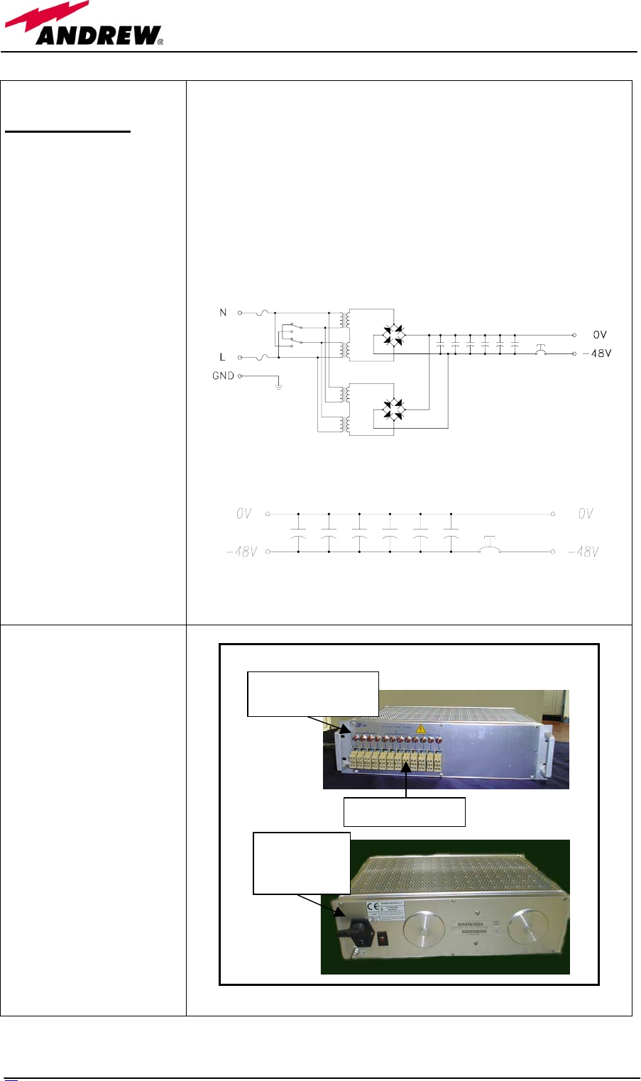
Module name:
TRS/TRSN
Description
TRS/TRSN provides centralised supply to all remote units through
individual outputs with short circuit protection switches.
Main supply (230Vac or 115Vac) is converted into a -48Vdc.
TRS/TRSN supply unit has been designed to provide DC supply with
standard AWG14/16 copper line to the remote units. Maximum
allowed distance depends on copper section, remote unit current
consumption and voltage range.
A passive option is available if -48Vdc is already provided.
Active distribution
Passive distribution
Ports
TRS version is applicable
to all low power remote
units and TFAN20. It is
available with
• 24 supply outputs
• 12 supply outputs
TRSN version is applicable
to tri-band and medium
power remote units. It is
available with
• 12 supply outputs
Supply outputs
Short-protection
switch
Main fuses
and voltage
selector
94 User Manual
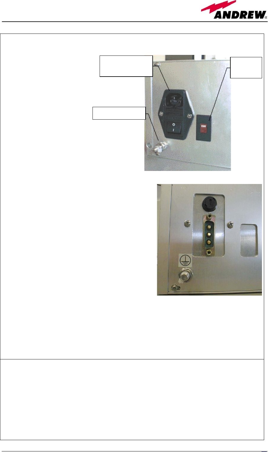
Mains connector
and fuses Voltage
selector
Ground screw
Power supply:
Two types of mains
(115/230VAC, 50/60Hz) can be
applied to the TRS/TRSNx2
versions which have been
designed for active distribution
of nominal -48VDC. Mains
connector and voltage selector
are placed on the back panel.
A TRS/TRSNx1 passive version is available in which a
direct current (–72 to –36 VDC) can be applied to the
system. Power supply cabling is provided: the blue cable
support –48 VDC, the black one 0 VDC.
Ground terminals are part of supply connectors. An external grounding terminal (screw) is also
available.
Mains connector and switch houses also the fuses:
• 250V, 4A delayed type for the active version
• -48V, 15A delayed type for the passive version
Warnings
• Caution: do not open the unit before disconnecting the mains. Internal assemblies can be
accessed by qualified personnel only
• Do not connect supply outputs to remote units before switching off the unit or disconnecting
the mains
• Being a DC supply provided, a wrong connection can damage the remote unit. Verify the
proper polarity before switching on the equipment.
9
5
MN024-04
TFBW installation
The TRS/TRSN subrack should be placed as near as possible to the TPRN to allow an easy cabling
in case of mixed fibre-copper cables. If the subrack mounting location is not provided with a good
air circulation, leave at least one unit free between subracks.
The kit includes a TRS/TRSN and a power cable.
1. Fix the TRS/TRSN subrack to the cabine with 4 screws
2. During the installation phase don’t connect the power cable to the main power line and don’t
switch on the TRS/TRSN
3. Set the switch in accordance with your main power line (115 Vac or 230 Vac) for universal
mains option. In case of negative supply option (-48 VDC), no switch is provided. Then
connect the ground screw.
4. Before connecting the wires from TRS/TRSN to the remote units, open all the fuses pulling the
red circle then connect electrical wires for the remote units
5. When all electrical wires have been connected and the system is ready to start, connect the
power cable, switch on the TRS/TRSN. Push one fuse at a time.
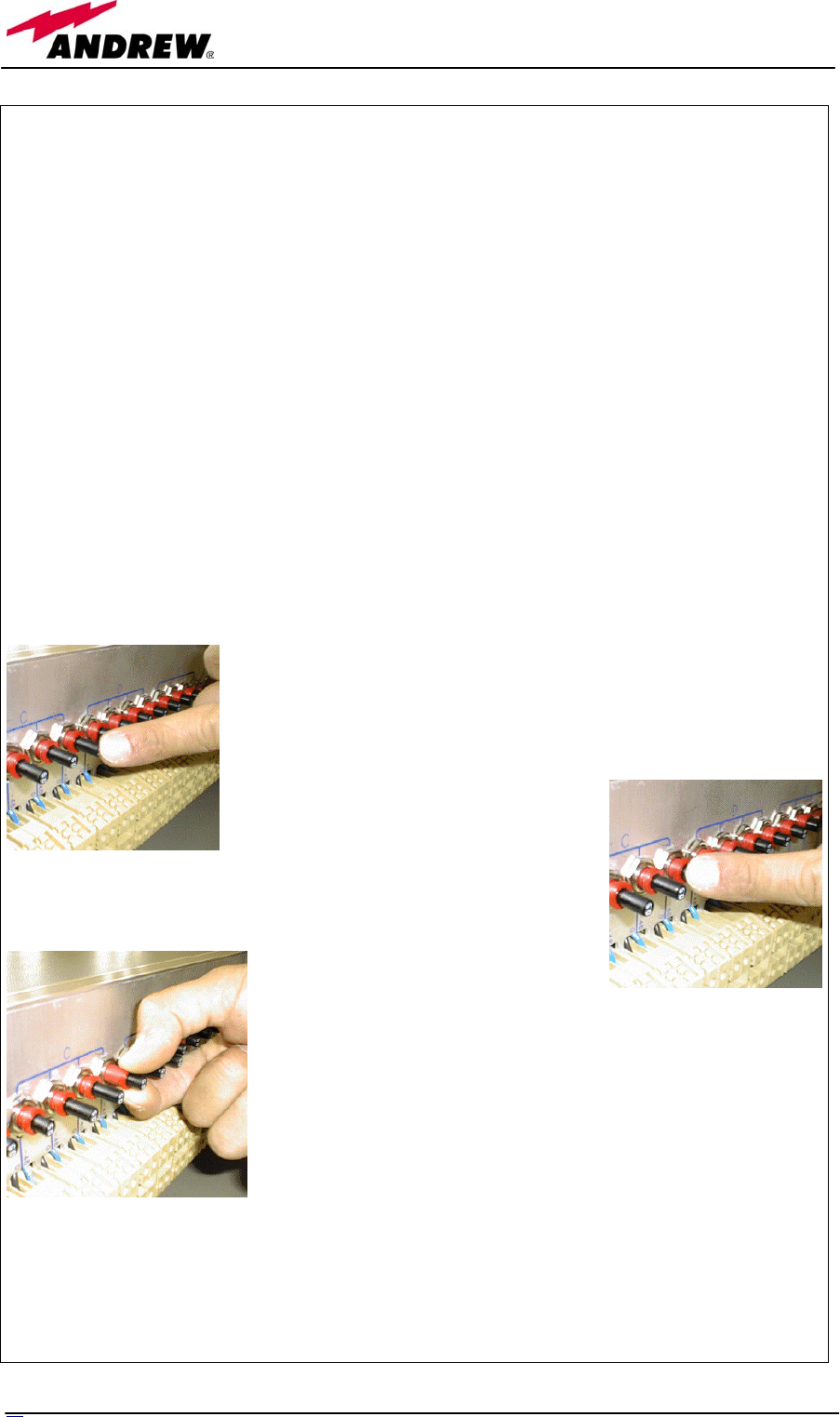
Each remote unit can be switched on-off by the relevant switch. The pictures below show how to
do it.
OFF position
ON position: push down the black button
To switch off pull out the red collar.
If a surge or an overloading condition occurred the switch automatically jump into an OFF
position.
96 User Manual

97
MN024-04
TRS/TRSN startup
• Check that power supply voltage selector is in the correct position (115 or 230 VAC). In
passive distribution version this selector is not present.
• Have all the switches in OFF position
• Check the connection polarity is not wrong
• Power on the TRS/TRSN unit through the back general switch
• Power on each remote unit through the front panel switches
• Check if the remote units shows the proper green supply led ON
TRS/TRSN Troubleshooting
If the remote unit doesn't appear to be properly supplied
• Check the fuses on the rear panel
• Check the voltage at the front panel screw connectors: nominal value without load is -59VDC,
nominal value with full load is -48VDC. If Those values are exceeded by 10% check the if the
mains are within the allowed limits. In passive distribution version, the output voltage depends
on the supply source.
• Check the voltage at the remote side it should be in the range -36 to -72 VDC that is the
maximum allowed range admitted by the remote units.
If the protection switch jump always in OFF position
• Check if any short on the line
• Check if the remote unit shows the nominal current power consumption.
• Check if any long period overshooting related to the mains supply.
If the fuses blow up after a power-on with all the front switches ON, there should be a too high
initial peak current transient: check the proper fuse (delayed type) or substitute with an higher
current fuse (i.e. 6A or 10 A). If the problem still persists check the proper ground /mains
connection.