Andrew Wireless Innovations Group M17P26 ION-M17P/26 EU User Manual Additional information on SM2009
Andrew Wireless Innovations Group ION-M17P/26 EU Additional information on SM2009
user manual
Extension Unit
ION™-M17P/26 EU
(Q-cabinet)
User's Manual
MF0133AUA

User’s Manual for
ION™-M17P/26 EU
Page 2 Manual MF0133AUA.doc
© Copyright 2011 CommScope, Inc.
All rights reserved.
Andrew Solutions is a trademark of CommScope, Inc.
All information contained in this manual has been revised thoroughly. Yet Andrew
Solutions accepts no liability for any omissions or faults.
Andrew Solutions reserves the right to change all hard- and software characteristics
without notice.
Names of products mentioned herein are used for identification purposes only and
may be trademarks and / or registered trademarks of their respective companies.
No parts of this publication may be reproduced, stored in a retrieval system,
transmitted in any form or by any means, electronical, mechanical photocopying,
recording or otherwise, without prior written permission of the publisher.
Andrew Wireless Systems GmbH, 17-November -2011

Page 3
TABLE OF CONTENTS
1. GENERAL 5
1.1. USED ABBREVIATIONS 5
1.2. HEALTH AND SAFETY WARNINGS 6
1.3. ABOUT ANDREW SOLUTIONS 8
1.4. INTERNATIONAL CONTACT ADDRESSES FOR CUSTOMER SUPPORT 9
2. FUNCTIONAL DESCRIPTION 11
2.1. PURPOSE 11
2.2. THE ION-M17P/26 EU 11
2.3. THE ION-M26 EU (STANDALONE VERSION) - FOR WIMAX 12
3. COMMISSIONING 14
3.1. MECHANICAL INSTALLATION 14
3.1.1. General 14
3.1.2. Wall and Pole Mounting 15
3.2. ELECTRICAL INSTALLATION 16
3.2.1. General 16
3.2.2. Connections 17
3.2.3. Grounding 17
3.2.4. Connection to the Main Unit 18
3.2.5. Connection of RF Cables to Combining Unit 18
3.2.6. Power Connection 19
3.3. COMMISSIONING 20
4. ALARMS 24
4.1. BITE AND ALARMS 24
4.2. HANDLING OF ALARMS 24
4.3. ALARM STATUS 24
4.4. TROUBLESHOOTING 25
5. MAINTENANCE 26
5.1. OPENING AND CLOSING OF THE CABINET 27
5.2. REPLACEMENT OF POWER SUPPLY 28

User’s Manual for
ION™-M17P/26 EU
Page 4 Manual MF0133AUA.doc
5.3. REPLACEMENT OF FAN UNIT 29
5.4. SPECIFICATIONS 30
5.4.1. Electrical Specifications of ION-M17P EU 30
5.4.2. Electrical Specifications of ION-M26 EU 30
5.4.3. Mechanical Specifications of ION-M17P/26EU 30
5.4.4. Environmental and Safety Specifications of ION-M17P/26EU 31
5.5. SPARE PARTS LIST 31
6. INDEX 32
FIGURES AND TABLES
figure 3-1 Wall mounting........................................................................................... 15
figure 3-2 Pole mounting .......................................................................................... 15
figure 3-3 ION-M17P/26 EU, connector flange, exemplary....................................... 17
figure 3-4 Grounding bolt.......................................................................................... 17
figure 3-5 AC mains plug .......................................................................................... 19
figure 3-6 DC mains plug.......................................................................................... 19
figure 5-1 Locker with key......................................................................................... 27
figure 5-2 Front and top cover screws ...................................................................... 27
figure 5-3 Power supply screws................................................................................ 28
figure 5-4 Fan unit screws ........................................................................................ 29
figure 5-5 Fan-connector cable................................................................................. 29
table 1-1 List of international contact addresses....................................................... 10
table 4-1 Status LED alarms..................................................................................... 25
table 5-1 Specified torques for various screw types ................................................. 26
1. GENERAL
1.1. USED ABBREVIATIONS
3GPP 3rd Generation Partnership Project
AC/DC Alternating current / Direct Current
AIMOS Andrew Integrated Management and Operating System
ALC Automatic Level Control
BITE Built-In Test Equipment
BTS Base Transceiver Station
CE "Conformité Européenne" ("European Conformity")
CD Compact Disk
CPD Channel Power Detection
DL Downlink
DoC Declaration of Conformity
EDGE Enhanced Data Rates for GSM Evolution
EN European Norm
EP Extension Port
ESD Electrostatic Discharge
ETS European Telecommunication Standard
EU Extension Unit
GSM Global System for Mobile Communication
GND Ground
GUI Graphical User Interface
ICP3 Intercept Point 3rd order
ID No Identification Number
ION Intelligent Optical Network
IP Ingress Protection
ISO International Organization for Standardization
LED Light Emitting Diode
LMT Local Maintenance Terminal
LTE Long Term Evolution
MIMO Multiple Input Multiple Output
MS Mobile Station
MU Main Unit
NF Noise Figure
OTRx Optical Transceiver = SRMU (Subrack Master Unit)
PDU Power Distribution Unit
PG Packing Gland
PIM Passive Intermodulation
R&TTE Radio & Telecommunications Terminal Equipment
Rev Revision
RF Radio Frequency
RU Remote Unit
RX Receiver
SNMP Simple Network Management Protocol
TS Technical Specification
TX Transmitter
UL Uplink
UMTS Universal Mobile Telecommunication System
UPS Uninterruptible Power Supply
VSWR Voltage Standing Wave Ratio
WCDMA Wideband Code Division Multiple Access
WDM Wavelength Division Multiplex

1.2. HEALTH AND SAFETY WARNINGS
1. Only suitably qualified personnel is allowed to work on this unit and only after
becoming familiar with all safety notices, installation, operation and maintenance
procedures contained in this manual.
2. Read and obey all the warning labels attached to the unit. Make sure that the
warning labels are kept in a legible condition and replace any missing or
damaged labels.
3. Obey all general and regional installation and safety regulations relating to work
on high voltage installations, as well as regulations covering correct use of tools
and personal protective equipment.
4. Keep operating instructions within easy reach and make them available to all
users.
5. It is the responsibility of the network provider to implement prevention measures
to avoid health hazards which may be associated to radiation from the antenna(s)
connected to the unit.
6. Note for a Class A digital device or peripheral:
This equipment has been tested and found to comply with the limits for a
Class A digital device, pursuant to part 15 of the FCC Rules. These limits
are designed to provide reasonable protection against harmful interference
when the equipment is operated in a commercial environment. This
equipment generates, uses, and can radiate radio frequency energy and, if
not installed and used in accordance with the instruction manual, may
cause harmful interference to radio communications. Operation of this
equipment in a residential area is likely to cause harmful interference in
which case the user will be required to correct the interference at his own
expense.
7. Make sure, access is restricted to qualified personnel.
8. Only licence holders for the respective frequency range are allowed to operate
this unit.
9. Corresponding local particularities and regulations must be observed. For national
deviations please refer to the respective documents included in the manual CD
delivered.
10. Use this equipment only for the purpose specified by the manufacturer. Do not
carry out any modifications or fit any spare parts which are not sold or
recommended by the manufacturer. This could cause fires, electric shock or other
injuries.
11. Due to power dissipation, the repeater may reach a very high temperature. Do not
operate this equipment on or close to flammable materials.
Page 6 Manual MF0133AUA.doc

12. Before opening the unit, disconnect mains.
13. ESD precautions must be observed! Before commencing maintenance work, use
the available grounding system to connect ESD protection measures.
14. This unit complies with European standard EN60950.
15. Make sure the repeater settings are according to the intended use (see also
product information of manufacturer) and regulatory requirements are met.
16. Although the repeater is internally protected against overvoltage, it is strongly
recommended to earth the antenna cables close to the repeater’s antenna
connectors for protection against atmospheric discharge.
17. Laser radiation! Do not stare into the beam; do not view it directly or with optical
instruments.

Page 8 Manual MF0133AUA.doc
1.3. ABOUT ANDREW SOLUTIONS
Andrew Wireless Systems GmbH based in Buchdorf / Germany, is a leading
manufacturer of coverage equipment for mobile radio networks, specializing in high
performance, RF and optical repeaters. Our optical distributed networks and RF
repeater systems provide coverage for every application: outdoor use, indoor
installations, tunnels, subways and many more.
Andrew Wireless Systems GmbH has unparalleled experience in providing RF
coverage and capacity solution for wireless networks in both indoor and outdoor
environment and belongs to Andrew Solutions, a CommScope Company.
Andrew Solutions is the foremost supplier of one-stop, end-to-end radio frequency
(RF) solutions. Our products are complete solutions for wireless infrastructure from
top-of-the-tower base station antennas to cable systems and cabinets, RF site
solutions, signal distribution, and network optimization.
Andrew Solutions has global engineering and manufacturing facilities. In addition, it
maintains field engineering offices throughout the world.
We operate a quality management system in compliance with the requirements of
ISO 9001. All equipment is manufactured using highly reliable material. In order to
ensure constant first-rate quality of the products, comprehensive quality monitoring is
conducted at all fabrication stages. Finished products leave the factory only after a
thorough final acceptance test, accompanied by a test certificate guaranteeing
optimal operation.
Note: Exceptions of and national deviations from this intended use may be
possible. To observe corresponding local particularities and
regulations, please refer to the respective documents (also in
national language) which are included in the manual CD delivered.
To make the most of this product, we recommend you carefully read the instructions
in this manual and commission the system only according to these instructions.
For technical assistance and support, please also contact the local office or Andrew
Solutions directly at one of the addresses listed in the following section.

1.4. INTERNATIONAL CONTACT ADDRESSES FOR CUSTOMER SUPPORT
Americas:
Canada United States
Andrew Solutions Canada Andrew Solutions,
Andrew LLC, A CommScope Company
Mail 620 North Greenfield Parkway
Garner, NC 27529
U.S.A. Mail 620 North Greenfield Parkway
Garner, NC 27529
U.S.A.
Phone +1-905-878-3457 (Office)
+1-416-721-5058 (Mobile) Phone +1-888-297-6433
Fax +1-905-878-3297 Fax +1-919-329-8950
E-mail Peter.Masih@commscope.com,
WIsupport.us@commscope.com
E-mail WIsupport.us@commscope.com
Brazil & South America Mexico, Central America &
Caribbean region
CommScope Cabos do Brasil Ltda. Andrew Corporation Mexico,
SA DE CV
Mail
Av. Com. Camilo Julio 1256
Zonal Industrial CP 597
Sorocaba SP 18086-000
Brazil
Mail
Av. Insurgentes Sur 688, Piso 6
Col. Del Valle, CP: 03100
Mexico City
Mexico
Phone + 55-15-9104-7722 Phone
+52-55-1346-1900 (Office)
+52-1-55-5419-5260 (Mobile)
Fax + 55-15-2102-4001 Fax +52-55-1346-1901
E-mail WIsupport@commscope.com
E-mail WIsupport@commscope.com
APAC Countries:
China, India and Rest of Asia Australia & New Zealand
Andrew International Corporation Andrew Corporation (Australia) Pty Ltd.
Mail
Room 915, 9/F
Chevalier Commercial Centre
8 Wang Hoi Rd
Kowloon Bay
Hong Kong
Mail
Unit 1
153 Barry Road
Campbellfield
VIC 3061
Australia
Phone +852-3106-6100 Phone +613-9300-7969
Fax +852-2751-7800 Fax +613-9357-9110
E-mail WIsupport.China@commscope.com
E-mail WIsupport.Australia@commscope.com

Page 10 Manual MF0133AUA.doc
Europe:
United Kingdom France
Andrew Solutions UK Ltd CommScope France
Mail
Unit 15, Ilex Building
Mulberry Business Park
Fishponds Road
Wokingham Berkshire
RG41 2GY
England
Mail
Immeuble Le Lavoisier
4, Place des Vosges
92052 Courbevoie
France
Phone +44-1189-366-792 Phone +33-1 82 97 04 00
Fax +44-1189-366-773 Fax +33-1 47 89 45 25
E-mail WIsupport.uk@commscope.com
E-mail WIsupport@commscope.com
Germany Czech Republic
Andrew Wireless Systems GmbH Andrew Solutions Czech Republic
C-Com, spol. s r.o
Mail Industriering 10
86675 Buchdorf
Germany Mail U Moruší 888
53006 Pardubice
Czech Republic
Phone +49-9099-69-0 Phone +420-464-6280-80
Fax +49-9099-69-930 Fax +420-464-6280-94
E-mail WIsupport@commscope.com
E-mail WIsupport@commscope.com
Austria Switzerland
Andrew Wireless Systems (Austria) GmbH Andrew Wireless Systems AG
Mail Weglgasse 10
2320 Wien-Schwechat
Austria Mail Tiergartenweg 1
CH-4710 Balsthal
Switzerland
Phone +43-1706-39-99-10 Phone +41-62-386-1260
Fax +43-1706-39-99-9 Fax +41-62-386-1261
E-mail WIsupport.austria@commscope.com
E-mail WIsupport.ch@commscope.com
Italy Spain and Portugal
Commscope Italy S.r.l., Faenza, Italy Andrew Solutions España S.A.
A Commscope Company
Mail Via Mengolina, 20
48018 Faenza (RA)
Italy Mail
Avda. de Europa, 4 - 2ª pta.
Parque Empresarial La Moraleja
28108 Alcobendas (Madrid)
Spain
Phone +39-0546-697111 Phone +34-91-745-20 40
Fax +39-0546-682768 Fax +34-91-661-87 02
E-mail WIsupport.italia@commscope.com
E-mail WIsupport.iberia@commscope.com
table 1-1 List of international contact addresses

2. FUNCTIONAL DESCRIPTION
2.1. PURPOSE
Cellular telephone systems transmit signals in two directions between base
transceiver station (BTS) and mobile stations (MS) within the signal coverage area.
If weak signal transmissions occur within the coverage area because of indoor
applications, topological conditions or distance from the transmitter, extension of the
transmission range can be achieved by means of an optical distribution system.
Such a system contains an optical Master Unit and several Remote Units. The
number of the Remote Units depends on the hardware and software configuration.
The Remote Units are connected to the Master Unit with optical links. The optical
loss must be less than 10 dB inclusive optical couplers or splitters.
The Master Unit is the connection to the base transceiver stations. The configuration
of a Master Unit depends on the number of the Remote Units and the frequency
range.
WDM (Wave Division Multiplex) filters are integrated in the optical modules. For the
UL, a wavelength within 1540 nm – 1562 nm is used. For the DL, a wavelength of
1310 ±20 nm is used. The maximum output power for the UL and DL is 5.7 mW.
2.2. THE ION-M17P/26 EU
The ION-M17P/26 EU (Intelligent Optical Network; MMR) is a high-power dual-band
Extension Unit (EU). It is used in conjunction with a Master Unit and a Main Unit
containing the optical transceiver (OTRx) in the ION-M optical distribution system.
This system is able to transport the whole AWS 1700 MHz band wide
simultaneously, providing a cost-effective solution for distributing capacity from one
or more base stations. Optionally, for 2600 MHz WiMAX in TDD * mode is available.
The ION-M17P/26 EU is connected via extension cable bridge to the Main Unit with
extension port. For a frequency band extension, the additional band (for ION-M17P
EU this is AWS) has just to be combined with the signal for the (Main) Remote Unit.
Then, the additional band is available on the extension port of the Main Unit.
The ION-M17P/26 EU transports signals on the RF layer in a very inexpensive
manner. This means that services from various operators can be transmitted
simultaneously from a cluster of base stations to a remote location over the same
fibre.
Any service or frequency band extension is achieved by adding an Extension Unit
(EU) without any impact to the installed network.
* TDD is the abbrev. of time-division-duplex

Page 12 Manual MF0133AUA.doc
The ION-M17P/26 EU has been specifically tested and optimized for CDMA2000,
EV-DO, WCDMA, and UMTS. Furthermore, it is provisioned for future improvements
to the modulation (e.g. HSDPA and OFDM) and frequency bands such as WiMAX.
The ION is easily set-up and supervised via a graphical user interface (GUI).
Extension Units can be commissioned through the use of built-in test equipment with
a minimum of commissioning required. The entire system may be monitored remotely
via an Andrew OMC. This is a comprehensive management platform with SNMP
protocol and X.733 standard implemented. Should a sophisticated interface not be
required, the master unit can be directly connected to the alarm interface of a base
station via relay alarming.
High-power, multi-operator support
Reduced visual impact form factor
Efficient, high power amplifier
Easy connection to Main Unit via cable bridge
Comprehensive operations and management system for configuration and
alarming
OMC with SNMP according to X.733 standard
Easy installation and commissioning
2.3. THE ION-M26 EU (STANDALONE VERSION) - FOR WIMAX
The ION-M26 EU is the most efficient solution to upgrade your Fiber-DAS to WiMAX.
This upgrade has nearly no impact to your installation and offers the possibility to
feed a common distribution or antenna network.
As the standard Andrew fiber DAS ION-M is service agnostic which enables a
transparent WiMAX TDD transport to 30 MHz adjacent spectrum for the Master Unit
to any Remote Unit. Only a single extension box (ION-M26 EU) has to be connected
to the Remote-Unit and the system upgrade to WiMAX is established.
With this easy upgrade leverages a fast WiMAX rollout especially in those areas
where difficult propagation conditions require a DAS solution even for 2G and 3G
services.
The small extension box ION-M26 EU co-sites to the standard ION-M Remote Unit
and needs no separate fiber back haul but a cable bridge to the Remote Unit.
At the Master Unit the WiMAX signal is combined with the 2G and 3G signals and
transported to the Remote Unit.
The Master Unit (MU) contains the interfaces to the BTS and towards the fiber
network. The MU also provides the system control functionality with interface for local
(web browsing) or remote-control (web browsing and SNMP), and also the backhaul
connection towards the OMC (SNMP).
The Remote Unit (RU) is connected by a single fiber, converts the optical signal back
to RF and holds the antenna ports and extension interface to the Extension-Unit (EU)
ION-M26 EU.
The Extension Unit (EU) supports the TDD mechanism for a SISO * channel with
multiple carriers up to an instantaneous bandwidth of 30 MHz. The TDD switching
information is retrieved for the WiMAX signal by analyzing the associated DL Map in
the master unit.
For the RU and the attached EU the alarm and control information is exchanged with
Master Unit on a sub carrier. At the Master Unit the alarms can be presented to the
BTS via alarm contact relays or can be sent to the Andrew OMC.
Efficient, high power amplifier
No additional fiber needed. WiMAX and 2G, 3G signals are transported on the
same optical link.
Compliant to 802.16e-2005, 802.16e, and the WiMAX approved Corrigenda,
two modifications
SNMP alarming and web-GUI
* SISO is the abbrev. of Single Input Single Output
3. COMMISSIONING
3.1. MECHANICAL INSTALLATION
3.1.1. General
Read the health and safety warnings in section 1.2 Health and Safety Warnings.
1. Do not install the unit in a way or at a place where the specifications
outlined in the Environmental and Safety Specifications leaflet of the
manufacturer are not met.
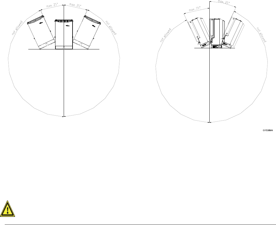
2. It is strongly recommended to install the unit vertically.
3. When mounting the Remote Unit, the connector flange (illustrated in
chapter 3.2.2 Connections) with the cables must point to the ground. A
maximum tilt angle of 25° to the horizontal position of the connector flange
must be kept in each mounting direction. For details, refer to chapter 5.4.3
Mechanical Specifications of ION-M17P/26EU. If a different installation of the
Remote Unit is required, please contact customer service for further
information.
4. It is recommended only to use the mounting hardware delivered by the
manufacturer. If different mounting hardware is used, the specifications for
stationary use of the Remote Unit must not be exceeded.
Note: Exceeding the specified load limits may cause the loss of warranty!
5. The unit is considerably heavy. Make sure that a suitable mounting surface
is used. Ensure there is adequate manpower to handle the weight of the
system.
Page 14 Manual MF0133AUA.doc
6. Due to power dissipation, the Remote Unit may reach a very high
temperature. Ensure sufficient airflow for ventilation. Above and below the
unit a minimum distance of 300 mm to ceiling, floor, etc. has to be kept.
Also observe the instructions in the individual mounting procedures.
7. For outdoor installations, the pre-mounted front cover must be installed.
8. For indoor installations where the ambient temperature can reach above
40°C, the cover has to be removed.
9. When connecting and mounting the cables (RF, optical, mains, ...) ensure
no water can penetrate into the unit through these cables.
If any different or additional mounting material is used, ensure that the mounting
remains as safe as the mounting designed by the manufacturer. Ensure that the
static and dynamic strengths are adequate for the environmental conditions of the
site. The mounting itself must not vibrate, swing or move in any way that might cause
damage to the Remote Unit.
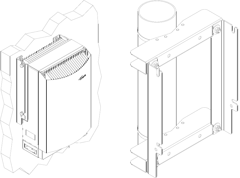
3.1.2. Wall and Pole Mounting
Wall and pole mounting equipment for the unit is available. For the according
mounting please refer to the mounting plan (drawing) that is part of the delivery.
figure 3-1 Wall mounting figure 3-2 Pole mounting
V1628M0 V1628M1

3.2. ELECTRICAL INSTALLATION
3.2.1. General
Read the health and safety warnings in section 1.2 Health and Safety Warnings.
1. This unit contains dangerous voltages. Loss of life, severe personal injury or
property damage can be the result if the instructions contained in this manual are
not followed.
2. Ground the unit before connecting power supply. A grounding bolt is provided on
the cabinet to connect the ground-bonding cable.
3. Although the Remote Unit is internally protected against over-voltage, it is
strongly recommended to earth the antenna cables close to the antenna
connectors of the Remote Unit for protection against atmospheric discharge. In
areas with strong lightning it is highly recommended to insert additional lightning
protection.
4. If the mains connector of the Remote Unit is not easily accessible, a disconnect
device in the mains circuit must be provided within easy reach.
5. Before connecting or disconnecting the mains connector at the Remote Unit,
ensure that mains supply is disconnected.
6. Make sure that an appropriate circuit breaker and an over-current limiting device
are connected between mains and Remote Unit.
7. A connection of mains supply to a power socket requires the power socket to be
nearby the Remote Unit.
8. Incorrectly wired connections can destroy electrical and electronic components.
9. To avoid corrosion at the connectors caused by electrochemical processes, the
material of the cable connectors must not cause a higher potential difference than
0.6 V (see electrochemical contact series).
10. Use an appropriate torque wrench for the coupling torque (25 N-m / 19 ft lb) of 7-
16 DIN connectors with 1-1/4 in opening to tighten the 7/16-type antenna
connectors. For example, use torque wrench of item no. 244377 available from
the Andrew e-catalog. Do NOT use your hands or any other tool (e.g. a pair of
pliers)! This might cause damage to the connector and lead to a malfunction of
the Remote Unit.
11. Use a voltage limiting device for unstabilized electric networks that frequently
generate spikes.
12. The unit complies with the surge requirement according to EN 61000-4-5 (fine
protection); however, it is recommended to install an additional medium (via local
supply connection) and/or coarse protection (external surge protection),
depending on the individual application, in order to avoid damage caused by
overcurrent.
13. Observe the labels on the front panels before connecting or disconnecting any
cables.
Page 16 Manual MF0133AUA.doc
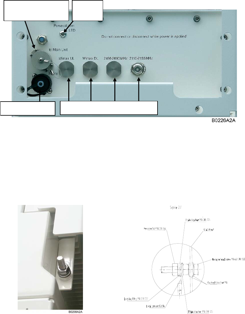
3.2.2. Connections
Extension connector
to main unit Status
LED
Mains connector N-connectors to Combining Unit
figure 3-3 ION-M17P/26 EU, connector flange, exemplary
3.2.3. Grounding
Grounding must be carried out. Connect an earth-bonding cable to the grounding
connection provided at the outside of the remote unit (see chapter 3.2.2
Connections). Do not use the grounding connection to connect external devices.
figure 3-4 Grounding bolt
After loosening the hex nut, connect the earth-bonding cable between the two
washers as illustrated in the figure above. Then, fasten all parts again with the hex
nut.
The PE cables must have a minimum cross section of 16 mm2.
3.2.4. Connection to the Main Unit
In order to connect the Extension Unit (EU) with the Main Remote Unit (RU), use a
cable bridge. Connect this cable bridge at the extension connector of the EU
(illustrated in 3.2.2 Connections) with the corresponding connector to EU at the RU.
Which connector to EU of the RU is exactly used is described in the corresponding
User’s Manual for the RU.
3.2.5. Connection of RF Cables to Combining Unit
The remote unit has N-connectors for connection to the Combining Unit. For its
location, please refer to chapter 3.2.2 Connections. For mounting the cable
connectors, it is recommended to refer to the corresponding documentation of the
connector manufacturer. The bending radius of the RF cables must remain within the
given specifications.
For the selection of cable and antenna it should be considered that, on the one hand,
a cable with higher loss is less expensive but, on the other hand, it impairs
performance.
Use an appropriate torque wrench for the coupling torque of N-type
connectors (2 N-m / 20 in lb), with 13/16 in opening to tighten the N-type
antenna connectors. For example, use torque wrench of item no. 244379
available from the Andrew e-catalog. Do NOT use your hands or any
other tool (e.g. a pair of pliers)! This might cause damage to the
connector and lead to a malfunction of the Remote Unit.
To minimize passive inter-modulation (PIM) distortion, attention has to
be paid to the physical condition of the connector junctions. Do not use
connectors that show signs of corrosion on the metal surface. Prevent
the ingress of water into the connector. Attach and torque the
connectors properly.
Page 18 Manual MF0133AUA.doc
3.2.6. Power Connection
Before connecting electrical power to the units, the system must be grounded as
described in the previous chapter.
Mains power must be connected at the mains connector of the unit (see chapter
3.2.2 Connections).
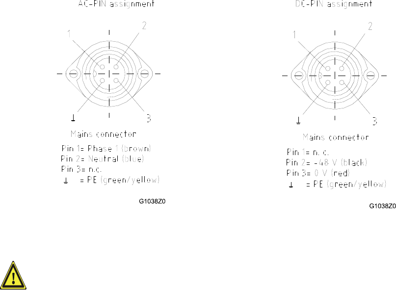
The power supply plug is part of the delivery. The correct wiring of the power supply
plug is as follows:
figure 3-5 AC mains plug figure 3-6 DC mains plug
For the AC power supply connection, a minimum cross section of 1.5
mm2 is required, and for the DC power supply connection a minimum
cross section of 2.5 mm2 is required. Each wire must observe the
applicable national regulations regarding loop impedance, voltage drop,
and methods of installation. Make sure to connect the correct voltage to
the unit.
Note: Do not connect or disconnect the power cord at the mains connector
while power is on. Turn off mains * power before connecting the
power cord at the remote unit, then, engage mains again.
* Mains power must be interrupted with an external mains breaker. For the mains
breaker, observe the following recommendation:
120 Volt / 20 Amp max. or 240 Volt / 16 Amp, single-phase, 50 / 60 Hz AC service is
needed, i.e. the external AC breaker should be 20 Amps max. for 120-Volt service or
16 Amps for 240-Volt service.
For the DC power supply, observe the local regulations of the DC service provider.

Page 20 Manual MF0133AUA.doc
3.3. COMMISSIONING
Read the health and safety warnings in chapter 1.2 as well as the description
carefully to avoid mistakes and proceed step by step as described!
Do not operate the Remote Unit without terminating the antenna connectors.
The antenna connectors may be terminated by connecting them to their
respective antennas or to a dummy load.
Only qualified personnel should carry out the electrical, mechanical,
commissioning and maintenance activities that require the unit to be powered
on when open.
When opening the Remote Unit do not damage the warranty labels on the
internal devices. The warranty is void if the seals are broken.
Ensure that all connections have been performed according to chapter 3.2.1
General.
Note: When an Extension Unit (EU) is installed to a Remote Unit (RU), the
Automatic Level Control (ALC) must be set in the RU, as described in
the software manual of the ION-M Master Controller.
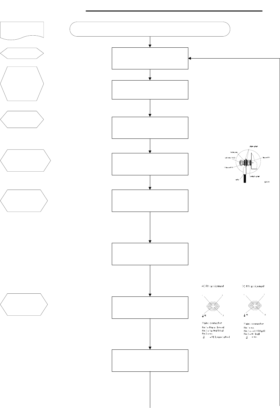
Commissioning an ION-M Extension Unit
Start
Mechanical installation
Fasten wall or pole mounting kit to wall or
pole.
Manual for
Extension Unit
Electrical connections
Connect grounding cable and
ground the EU.
Mains
Switch mains power on.
Philips
screwdriver
Screw driver
Spanner, size
13 mm
Connections to Main Unit
Use the cable bridge to connect the EU
with the Main Unit.
RF connection
Connect antenna cable to antenna port.
Electrical connections
Connect AC (DC) power to the power
cable. Ensure there is a circuit breaker
between mains and EU.
Mechanical installation
Mount EU to mounting kit, ensure suffient
air flow and avoid thermal short circuits.
Preparation
Unpack EU, EU accessories and
mounting kit.
G1055Z
0
G1055Z0
Mounting kit
Spanner, size
13 mm
Drilling
machine
Dowels
Screw driver
Earth cable
Spanner 13 mm
Cable bridge
Mains cable
Connecting kit
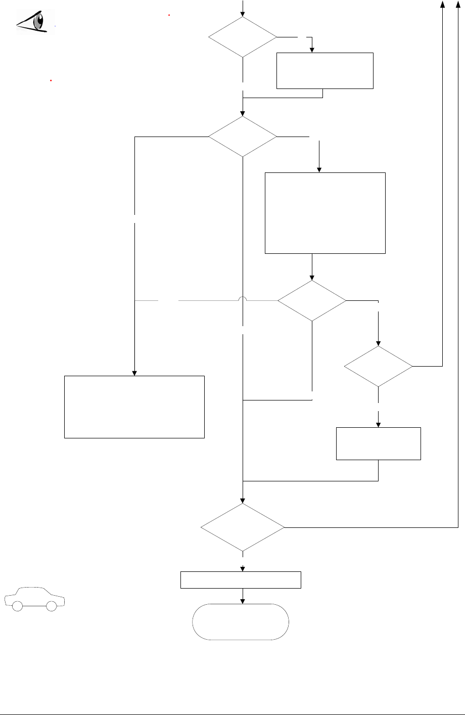
Output:
All EUs okay.
Go to MU
External error
Close the door (EUs with a door).
ALC alarm at RU: Decrease DL input power
of affected band.
VSWR alarm: Check antenna and cable.
LED status
Proceed to MU to set up the SW
Yellow
Yes
Internal Error
Change power supply (EUs with a
door).
Reduce environmental temperature.
Eliminate thermal short circuit.
Disconnect and connect mains. Fans
should run briefly (SW version > 2.4). If
not, replace the fans at EU.
MU: Change amplifier setting at MU
controller
Red
LED statusYellow
Green
Red
Finished setting up
all EUs?
Green
Spare EU
available?
Yes
Contact customer
service
No
Yes
LED on?
Check power switch inside EU
(EUs with door).
Check mains cabling.
Check mains power.
No
No
Page 22 Manual MF0133AUA.doc
For your notes:

Page 24 Manual MF0133AUA.doc
4. ALARMS
4.1. BITe AND ALARMS
The Built-In Test (BITe) concept comprises the monitoring of the power supplies, the
power amplifiers and the optical interface.
All alarms occurring can be checked via software at the Master Unit.
4.2. HANDLING OF ALARMS
In alarm condition, an alarm message is sent to the Master Controller.
If the reason for the alarm is cleared, the alarm will disappear. Otherwise, i.e. if the
alarm continues, a new alarm message will not be repeated.
A new alarm message will be generated if the alarm is interrupted for at least five
seconds after alarm clearance by the RU.
4.3. ALARM STATUS
Refer to the corresponding software documentation of the Master Unit for details.
For local supervision, a status LED on the connector flange of the remote unit gives
an indication of possible reasons for alarms. The position of the status LED is
illustrated in chapter 3.2.2 Connections. This table shows possible on-site measures
that could be checked before referring to the master unit alarm list.
Status LED indication Alarms Possible on-site measures
Green No alarm
Status ok
Door alarm Close the door (RUs with door).
Alarms not directly related to RU:
External alarms Check externally connected devices.
Optical alarm Rx
Check fibre loss of optical link.
Check optical connectors.
Clean optical connectors.
(MU: Check optical output power of
corresponding OTRx at master unit).
Orange
ALC alarm (MU: Decrease DL input power of
affected band).
Alarms directly related to RU:
Power 28 V Change power supply (RUs with door).
Replace the affected remote unit.
Red
Temperature Reduce environmental temperature.
Eliminate thermal short circuit.

Fan * Disconnect and connect mains. Fans
should run. If not, replace the fans at RU.
I²C Disconnect and connect mains.
Optical alarm Tx Exchange RU.
A
mplifier “Power
Down” (MU: Change amplifier setting at MU
controller).
Status LED off Mains
Check power switch inside of RU (RUs
with door).
Check mains cabling.
Check mains power.
table 4-1 Status LED alarms
* only applicable if the RU is equipped with a fan
For the position of the LED see chapter 3.2.2 Connections.
Explicit troubleshooting is available in the MU software, (software manual or WEB
Interface).
4.4. TROUBLESHOOTING
The status of the remote unit can be checked via the master unit (for details please
refer to the software manual of the Master Controller). Locally, the status can be
checked at the LED, see chapter 3.2.2 Connections.

Page 26 Manual MF0133AUA.doc
5. MAINTENANCE
Read the health and safety warnings in chapter 1.2.
Note: The remote unit does not require preventative maintenance
measures.
Maintenance of the ION-Mxxx should be performed on an FRU (Field Replaceable
Unit) basis only. Do not damage the warranty labels on the components, as this voids
the warranty.
The spare parts list contains only units that can be replaced without tuning or
soldering work.
Note: When sending back the unit, use an appropriate packaging, see
chapter 5.4.4 Environmental and Safety Specifications of ION-
M17P/26EU. We strongly recommend using the original packaging!
Note: Defect parts should only be replaced by original parts from the
supplier. All interventions inside the housing are at one’s own risk.
Note: During maintenance ensure that the unit has been disconnected
from mains.
Note: Before disconnecting any cables, label any unlabelled cables to
ensure correct reconnection.
To replace an FRU, use the appropriate tools. Replacement tools may be ordered
from the supplier. All screws have a right-hand thread, turn the tool clockwise for
tightening and counter-clockwise for loosening.
Do not over-tighten the connectors or screws. The table below shows various screws
with their respective torques.
Screw Type Tallow-drop Socket-head-cap Countersunk-head
Thread size Specified Torque (in Ncm)
M 2.0 40 not in use 40
M 2.5 82 not in use 82
M 3.0 145 100 145
M 4.0 330 330 330
M 5.0 650 tbd. 650
table 5-1 Specified torques for various screw types
If any FRU not contained in the following chapter needs to be replaced, contact
customer service for additional instructions.
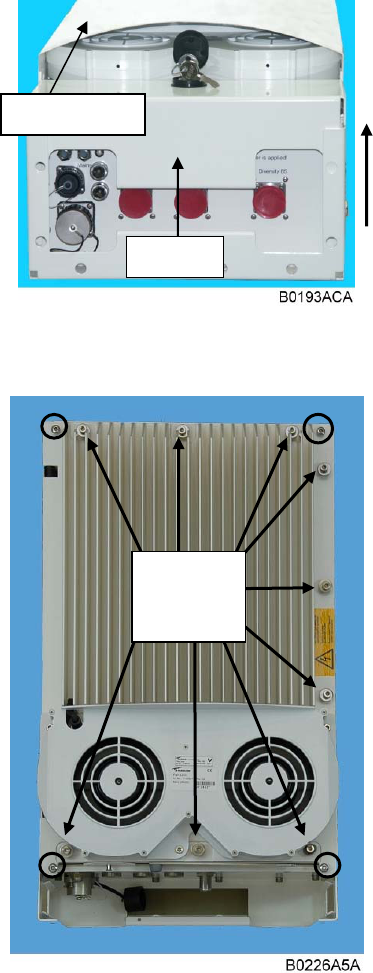
5.1. OPENING AND CLOSING OF THE CABINET
figure 5-1 Locker with key
figure 5-2 Front and top cover
screws
To open the cabinet of the remote unit, first
dismount the locker by unlocking it with the key
(which is part of the delivery) and pulling it out
carefully in direction of the arrow marked in
figure 5-1 Locker with key.
If the front cover is installed (see mechanical
installation in chapter) remove the cover by
loosening the four M5 socket head cap screws
(circle-marked in figure 5-2 Front and top cover
screws). Do not remove those screws. When
they are loosened, the front cover can be taken
off.
Before opening the cabinet, disconnect the
mains connector illustrated in chapter 3.2.2
Connections.
To open the cabinet, unscrew the nine M5
socket head cap screws (captive) of the top
cover of the remote unit (see figure 5-2 Front
and top cover screws).
After maintenance work, re-connect mains.
Close the cabinet.
To ensure safe operation, mount the front cover
if required (see mechanical installation in
chapter 3.1.1 General).
Check the status of the status LED. Ensure it is
showing a green light.
Front cover
Locker
Nine top
cover
screws
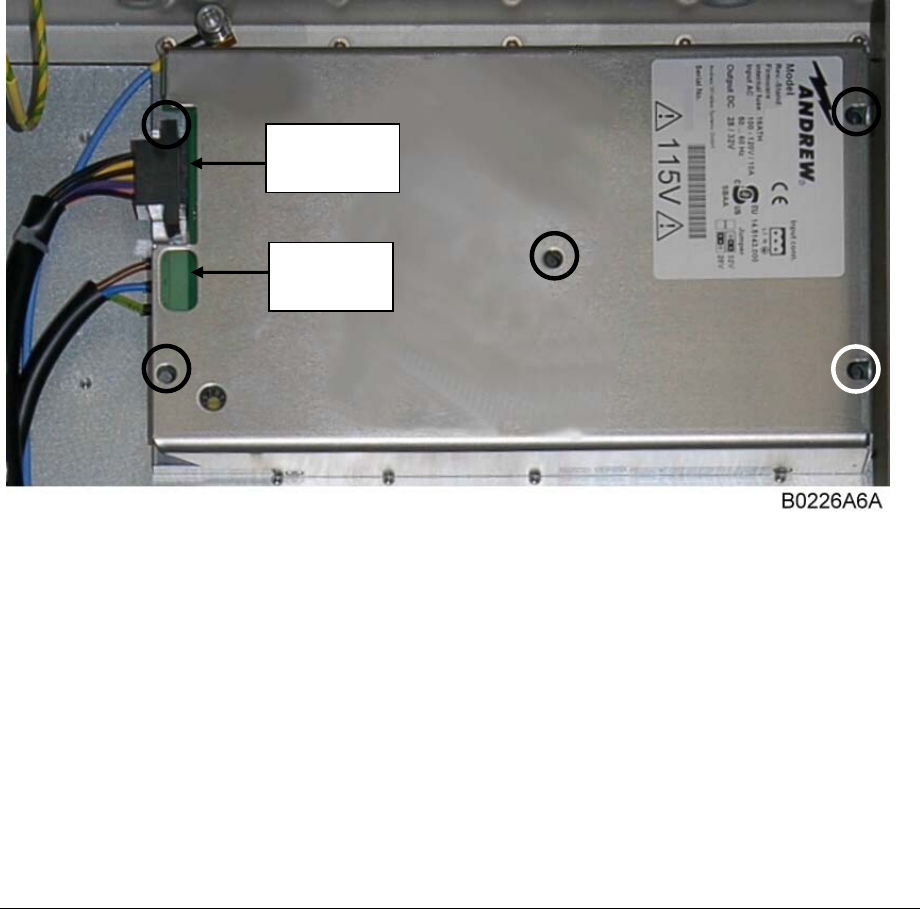
5.2. REPLACEMENT OF POWER SUPPLY
To remove the power supply, disconnect mains, mains cable and DC cable.
Unscrew the five hexagon socket head cap screws (circle-marked in illustration
below) with an Allen key.
Pull the power supply out.
Apply heat-conducting paste to the mounting surface of the new power supply.
Carefully insert the new power supply.
Fasten the five socket head cap screws.
Re-connect all cables.
figure 5-3 Power supply screws
Mains
connector
DC
connector
Page 28 Manual MF0133AUA.doc
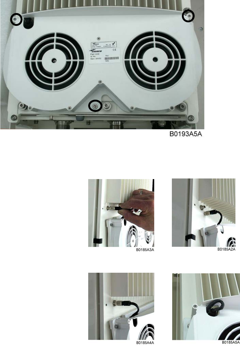
5.3. REPLACEMENT OF FAN UNIT
The fan unit is an FRU in the ION-M17P/26 EU.
figure 5-4 Fan unit screws
Unscrew the three M5x16 socket-head screws by which the fan unit is screwed to the
cabinet. Be careful not to lose the according washers.
Take off the fan unit and disconnect
the connector cable from the
cabinet.
To install the new fan unit, proceed
in reverse order.
In order not to squeeze the fan
connector cable, take care to
position it correctly after its re-
connection.
figure 5-5 Fan-connector cable
Page 30 Manual MF0133AUA.doc
5.4. SPECIFICATIONS
5.4.1. Electrical Specifications of ION-M17P EU
Electrical
Mains power 115 Vac or 230 Vac
Power supply Power consumption 250 Watts (AWS only)
Optical Link
BTS side (SMA) connectors 4
System optimized for BTS power 33 dBm
43 dBm
Antenna port (N) Connector N female
All data is subject to change without notice.
5.4.2. Electrical Specifications of ION-M26 EU
Electrical
Power supply Mains power 78 Vac to 264 Vac; 36 Vdc to 72 Vdc
Power consumption
per power class for SISO 130 W @ Med
220 W @ High
Connectors @ MU Single duplexed RF ports (SMA or N-type)
BTS side BTS types Micro: 33/43 dBm typical
Antenna port Connector 7/16 Female
5.4.3. Mechanical Specifications of ION-M17P/26EU
Height, width, depth * 546 x 320 x 260 mm (21.5x 12.6 x 10.3 in).
Weight 28 kg (61.7 Ib)
* Spacing required: 40 mm (1.66 in) around unit. Do not block air inlet and outlet. Vertical mounting -
300 mm above and below - is compulsory.
All data is subject to change without notice.
5.4.4. Environmental and Safety Specifications of ION-M17P/26EU
Note: For detailed information, please refer to the Environmental and
Safety Specifications leaflet of the supplier, related to ETS 300 019
(European Telecommunication Standard).
ION-M17P EU ION-M26EU
Operating temperature range -10° C to +50° C * -40 °C to +50°C
Ingress protection RF part
Fan part IP66
IP55 IP66
---
* with passive cooling maximum temperature: +40° C
All data is subject to change without notice.
5.5. SPARE PARTS LIST
The following lists contains all parts available for the remote unit. The configuration of
the delivered unit meets the requirements of the customer and can differ depending
on the state of the delivery.
Spare Parts List of the Extension Unit ION-M17P/26 EU:
Designation: ID No FRU
ION-M17P/26 EU 7576454
Cover 7160735 x
Locker 7163617 x
Fan Unit 7159547
Fin. Ampl. 350 W 2110-2155 43 dB 7542601-01
Fin. Ampl. 2640.5-2673.5 40 dB 7596193-00
RCM161 Kit EU OTRxRU 28V-NSO 7556916
PCB P3046 Connecting board ION 7512916
Power Supply Unit AC IN 115 V 7516410-00 x
Power Supply Unit DC IN 48 V 7159125 x
Manuals for ION-M17P/26 EU 7577576-00
Wall Mounting Kit 7160068 x
Cable RF Patch N-N 1000 mm 7544249 x
A
ccessor
y
Cable bridge 1200 mm RF Sucoform141 7164680 x
Pole Mounting Kit for K-/ L-/ Q-Cabinet 7163746 x
Protective Tube Kit 7162182 x
The manufacturer reserves the right to replace the spare parts listed above by
equivalent substitutes!

Page 32 Manual MF0133AUA.doc
6. INDEX
A
Abbreviations.......................................................... 5
Address of Andrew Wireless Systems GmbH....... 10
Alarms
Alarm Status .................................................... 24
Bite and Alarms ............................................... 24
Handling of Alarms .......................................... 24
List ................................................................... 25
RU ................................................................... 25
Andrew Solutions.................................................... 8
C
Commissioning
General............................................................ 20
Connection
RF Cables to Combining Unit .......................... 18
Connections
Connector Flange ............................................ 17
EU with Main Unit ............................................ 18
Power .............................................................. 19
Contact Addresses ................................................. 9
Customer Support Addresses................................. 9
F
Fan Connector Cable ........................................... 29
Fan Unit
Replacement.................................................... 29
Screws............................................................. 29
G
General................................................................. 27
Grounding............................................................. 17
H
Health and Safety Warnings................................... 6
I
Installation
Electrical.......................................................... 16
Mechanical ...................................................... 14
M
Mounting
General............................................................ 15
Wall.................................................................. 15
O
Opening and Closing the Cabinet......................... 27
P
Power Supply
Replacement ................................................... 28
R
Replacement of
Fan Unit........................................................... 29
Power Supply .................................................. 28
S
Spare Parts List.................................................... 31
Specifications
Electrical.......................................................... 30
Environmental and Safety................................ 31
Mechanical ...................................................... 30
T
Troubleshooting.................................................... 25