Andrew Wireless Innovations Group MRB-CELL Repeater/Booster User Manual Mr boost rev2
Andrew Wireless Innovations Group Repeater/Booster Mr boost rev2
UserManual.wiki
>
Andrew Wireless Innovations Group
>
MRB CELL User Manual
MANUAL
Navigation menu
Upload a User Manual
Namespaces
Wiki Guide
HTML
PDF
Info
Views
User Manual
Discussion / Help
Navigation
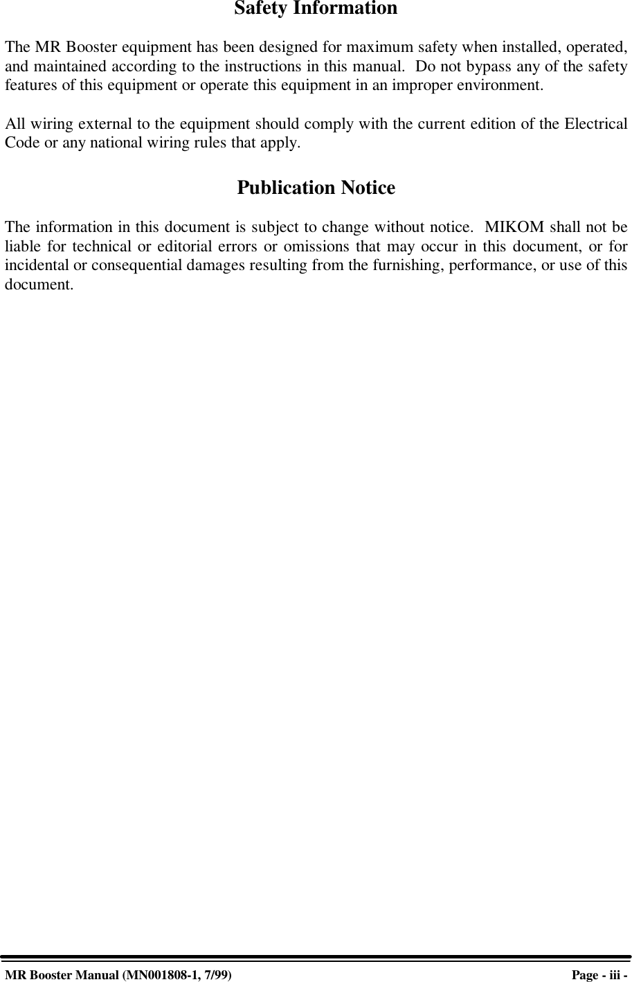
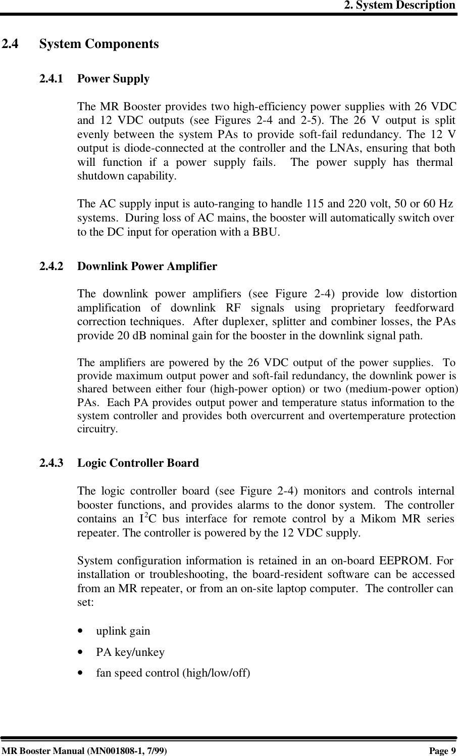
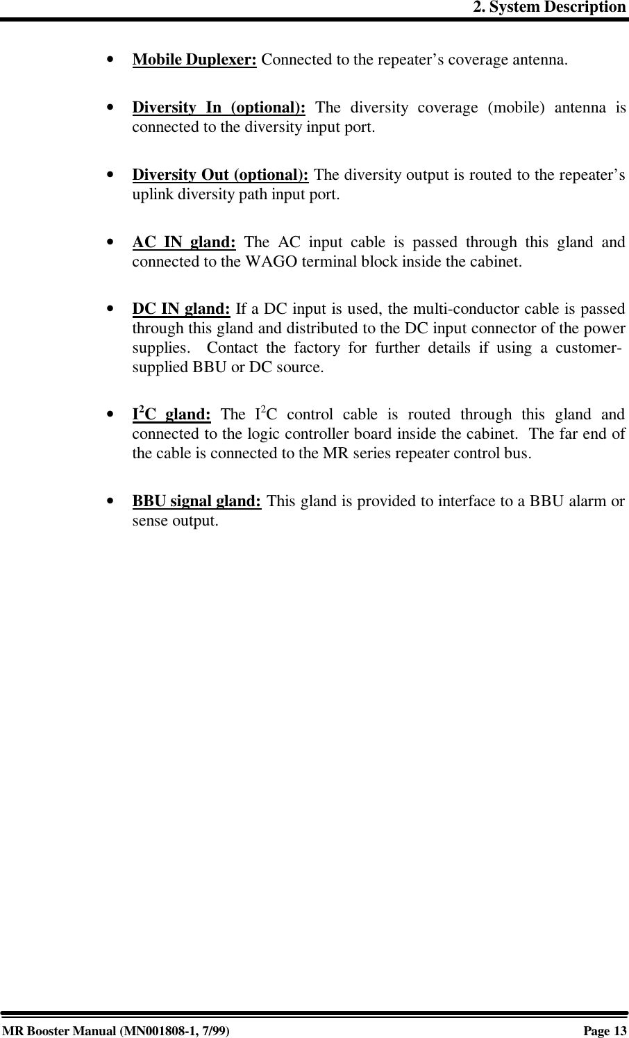
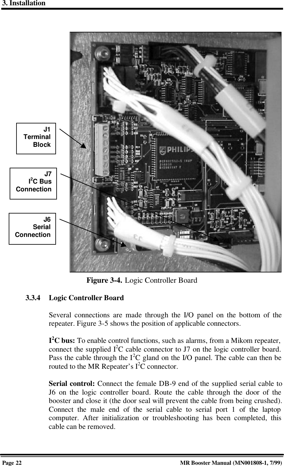
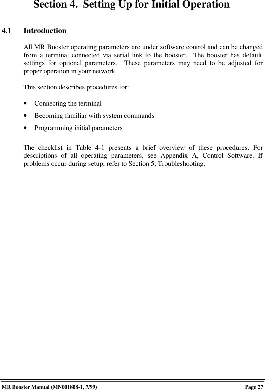
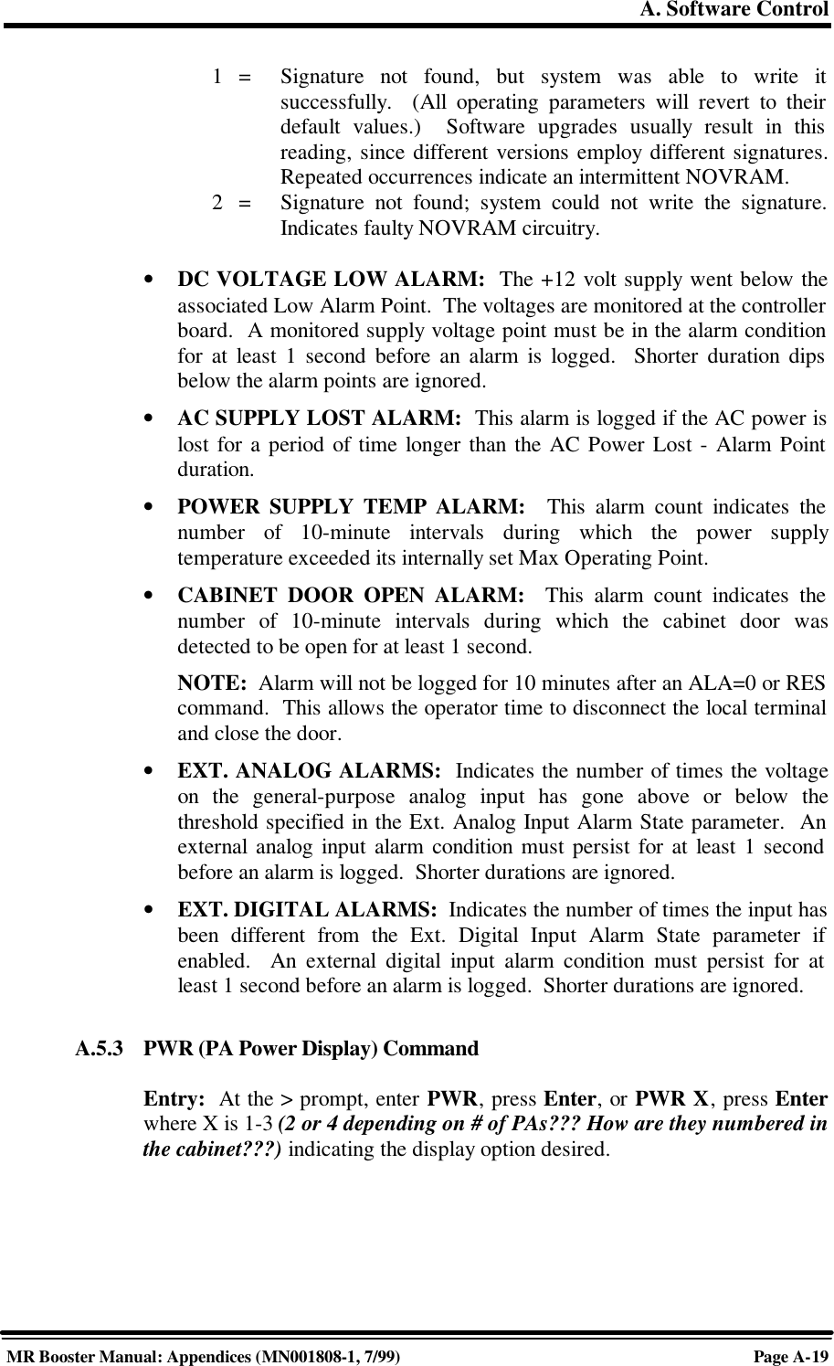
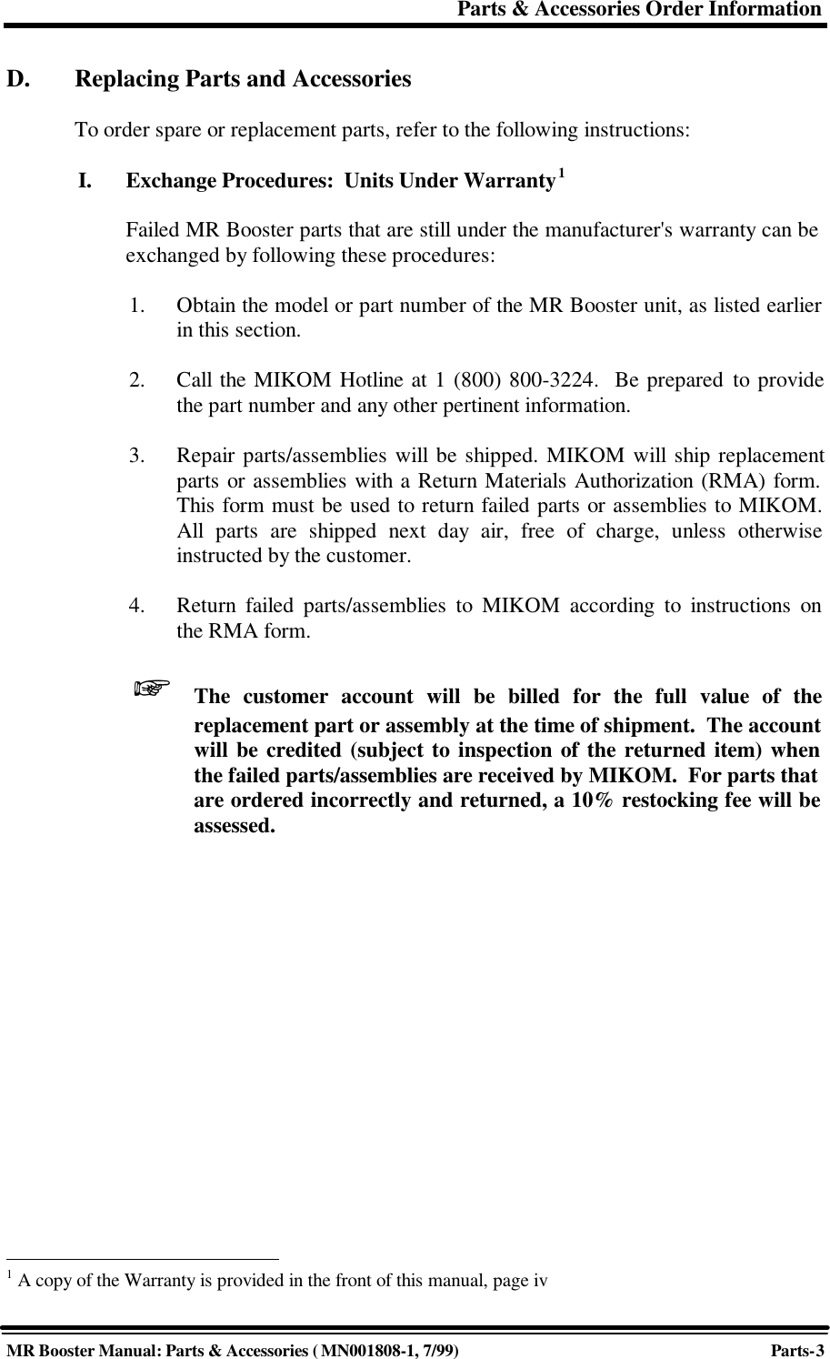
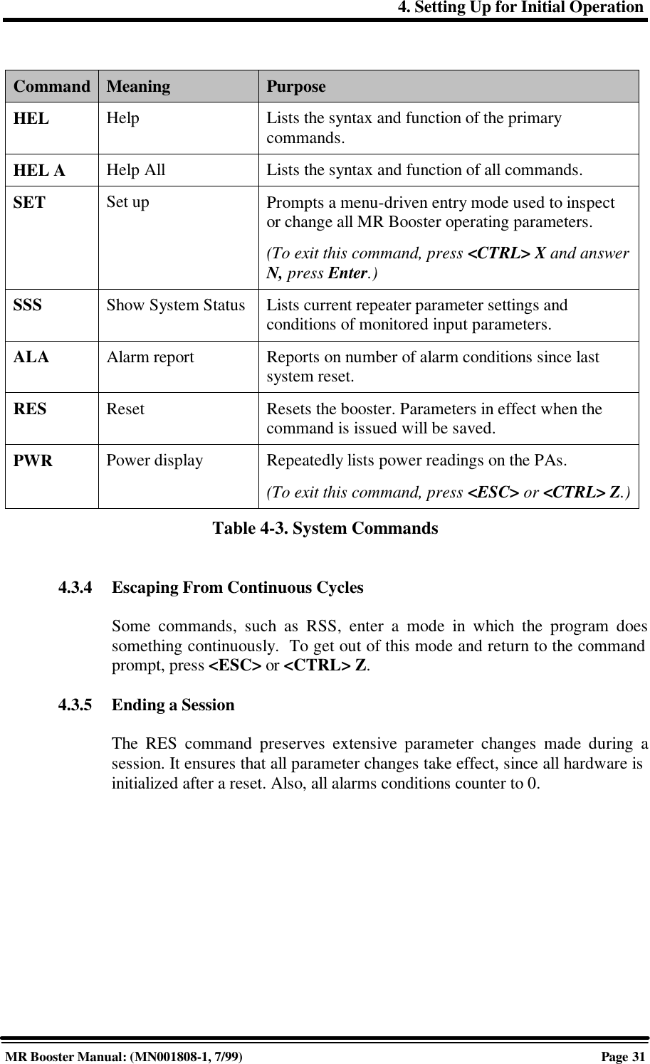
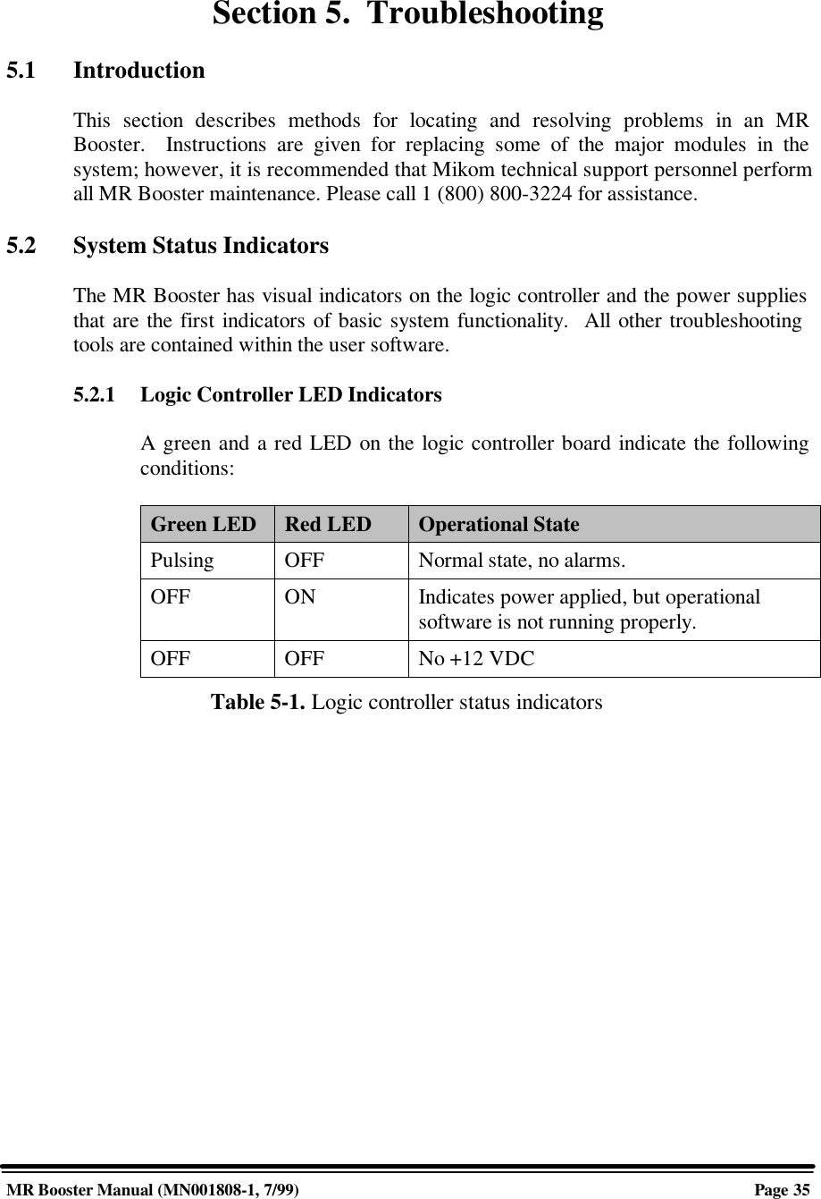
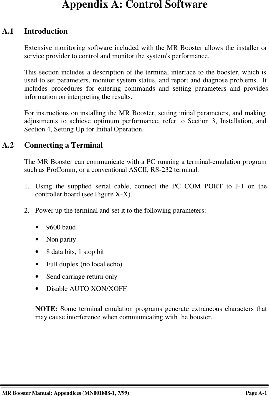
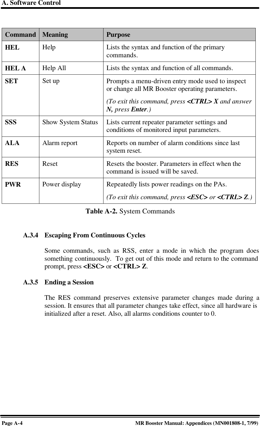
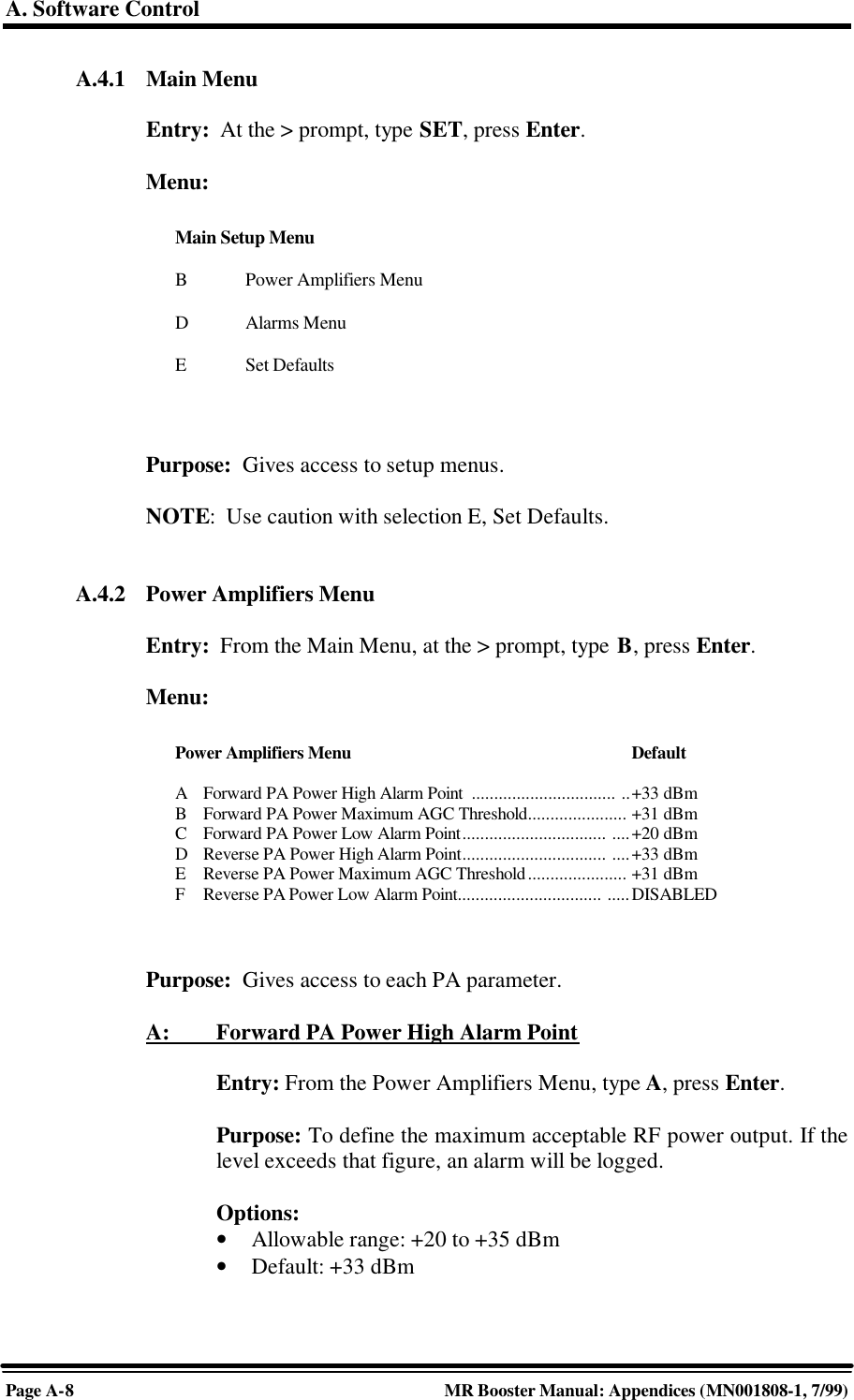
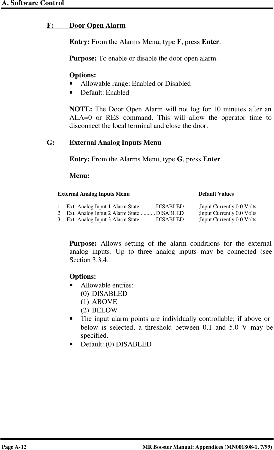
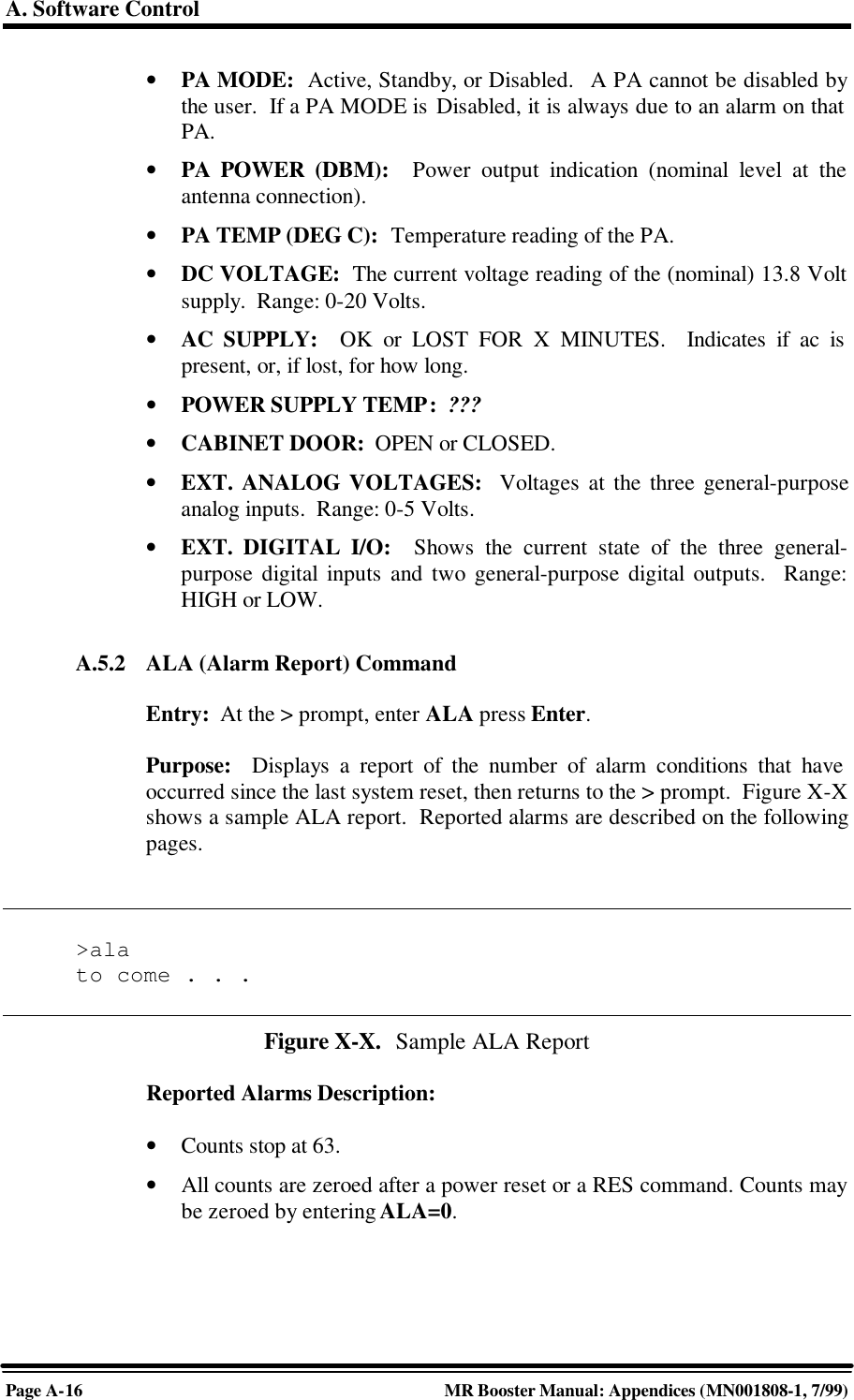
![4. Setting Up for Initial OperationMR Booster Manual: (MN001808-1, 7/99)Page 293. Power up the MR Booster. After about two seconds, the terminal should respondwith a welcome message.• If the response is garbled, check the terminal setup.• If there is no response, turn the booster OFF, then ON again. If there is stillno response, turn the unit OFF. Recheck the power hookup and the terminalhookup and configuration.4.3 Basic CommandsFollowing are basic rules and key commands for use with the MR Booster operatingsoftware.Symbol Definition><CTRL><ESC>Command Prompt. The system uses this prompt character to indicateit is ready to accept commands.Control Key. Used in combination with other keys.Escape Key. Escape is a single key marked ESC on most keyboards.Table 4-2. Command Definitions4.3.1 SyntaxSystem commands consist of three letters followed by a maximum of threedata fields, as follows:COM [FIELD 1 -] [FIELD 2 =] [FIELD 3] Enter• COM: Three-letter command.• FIELD 1: Up to four hex characters followed by a dash (-).• FIELD 2: Up to four hex characters followed by an equal (=) sign.• FIELD 3: Up to two hex characters.• Enter: Press the Enter key after each command.NOTE: Few commands require entry of data fields. After a command hasbeen entered, the system will prompt for data it needs. The system will ignoreunneeded data fields.](https://usermanual.wiki/Andrew-Wireless-Innovations-Group/MRB-CELL/User-Guide-53920-Page-35.png)
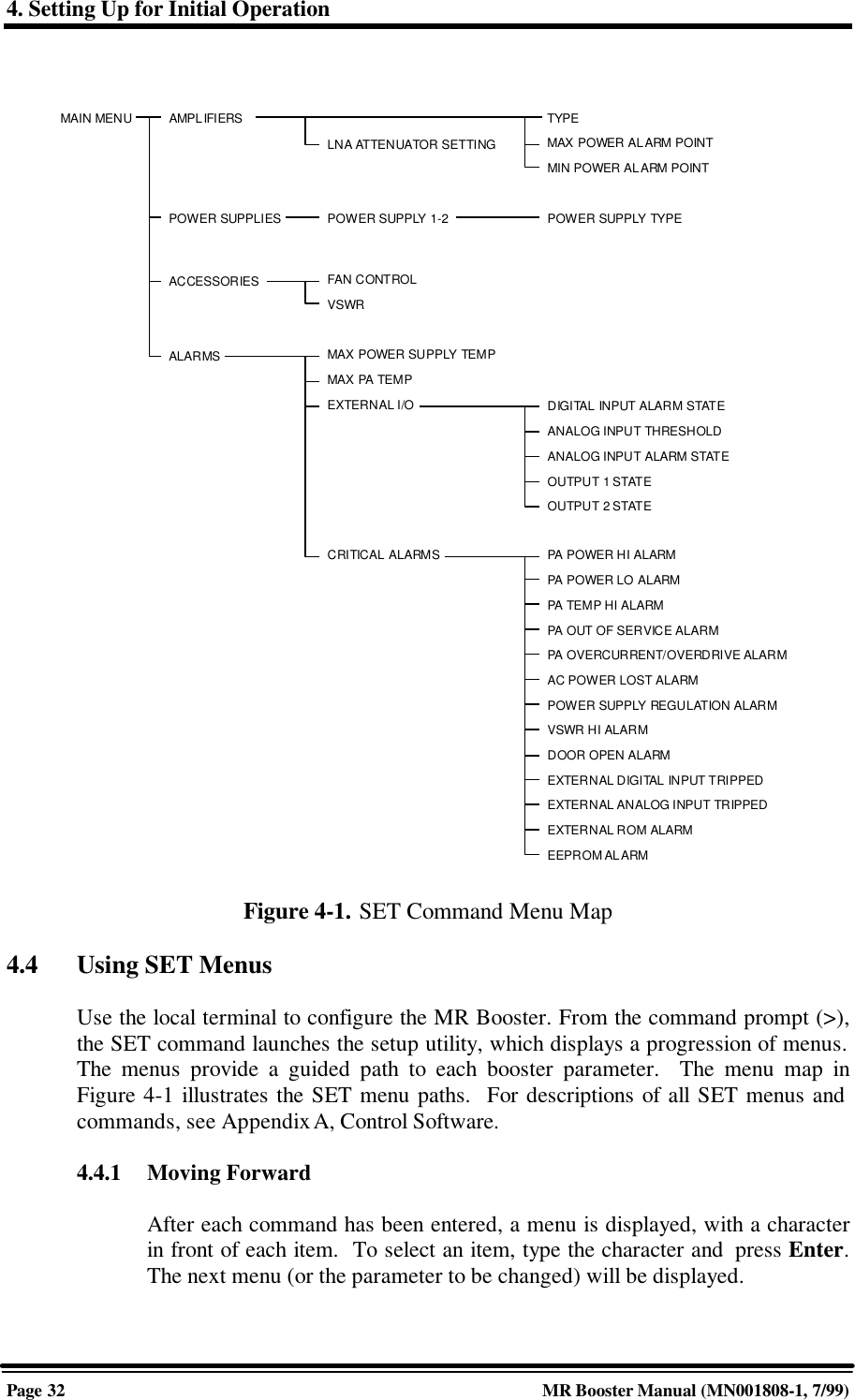
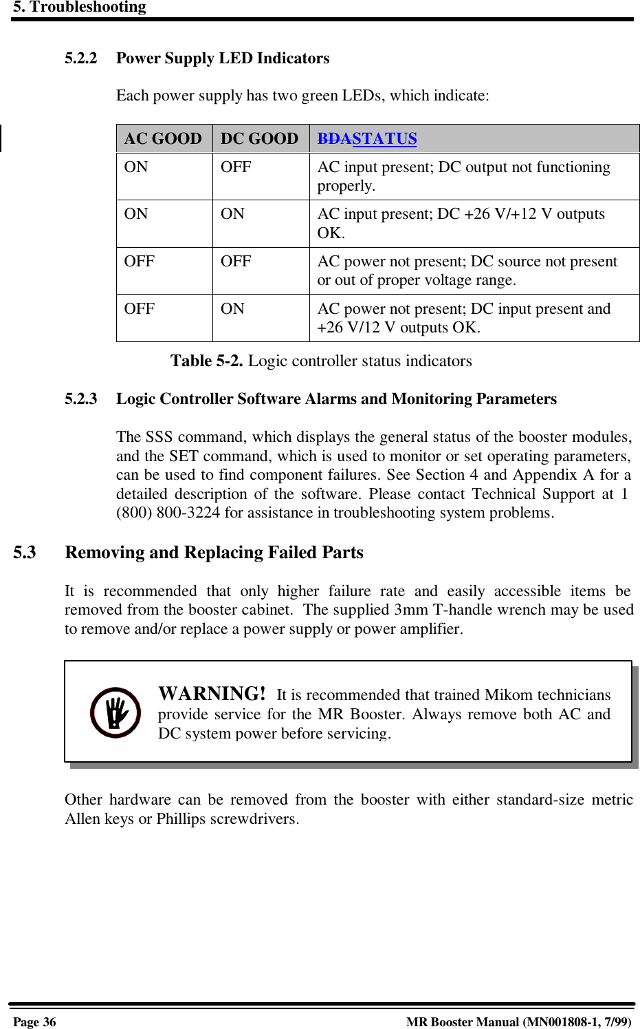

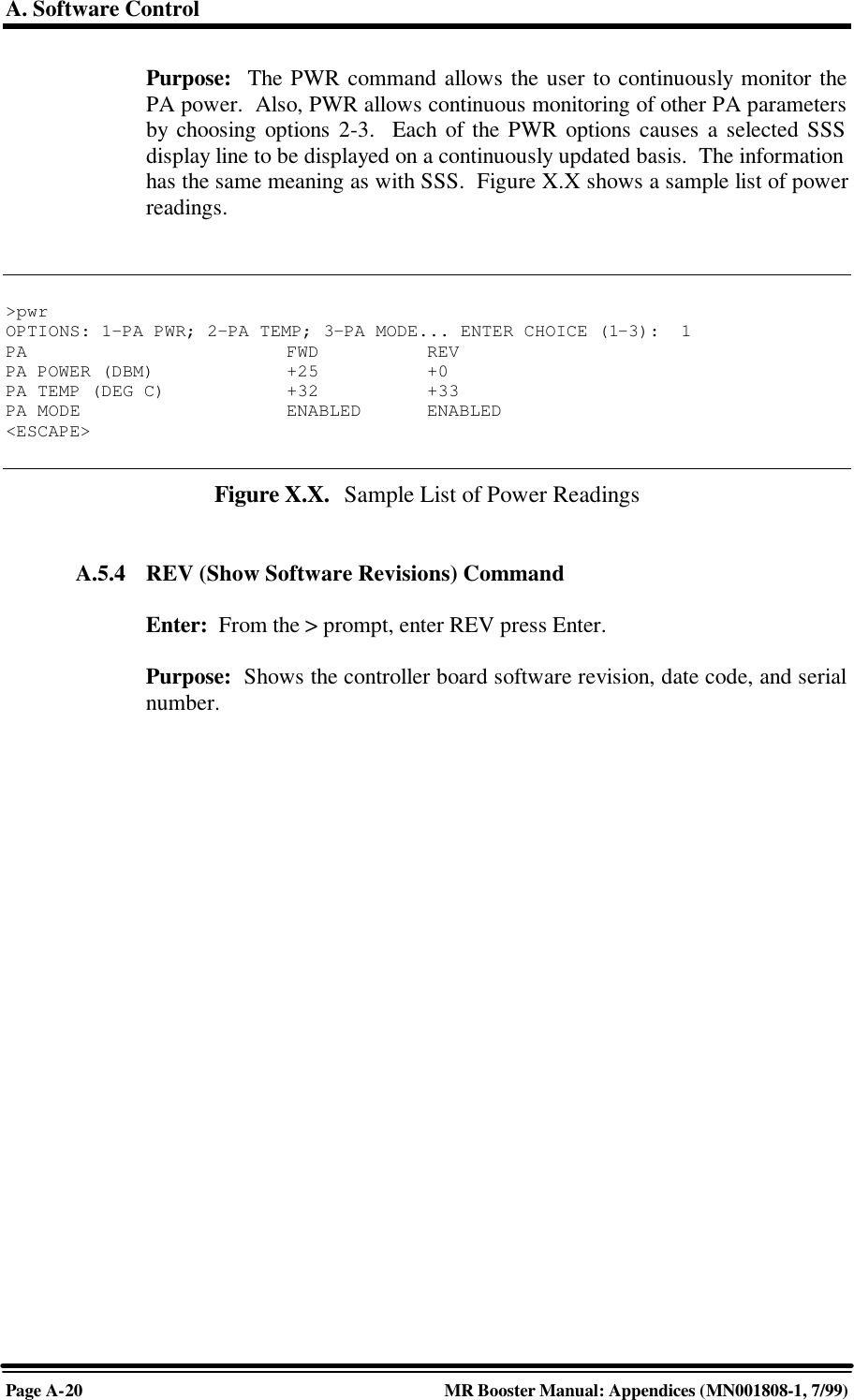
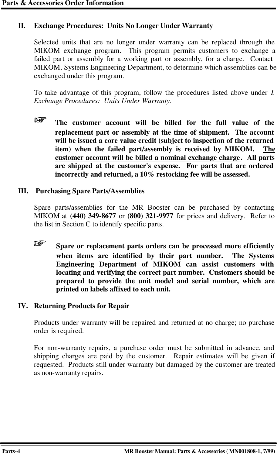
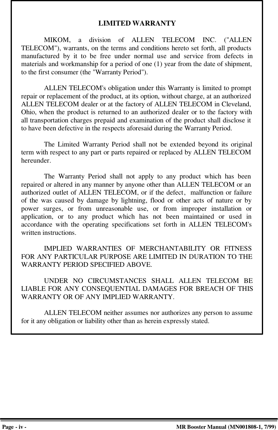
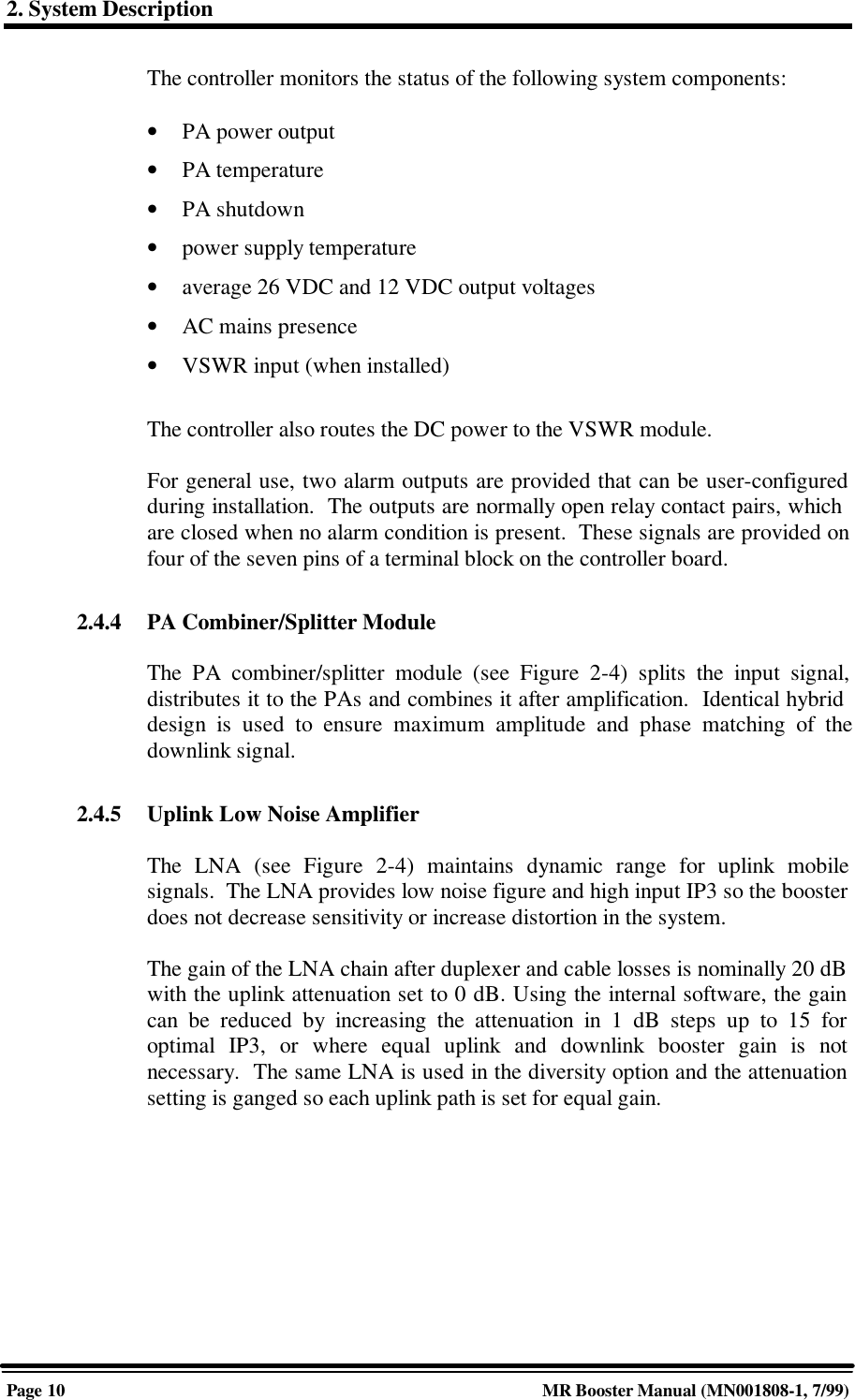
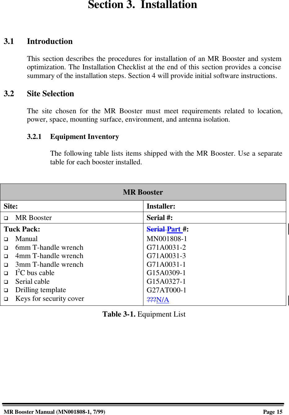
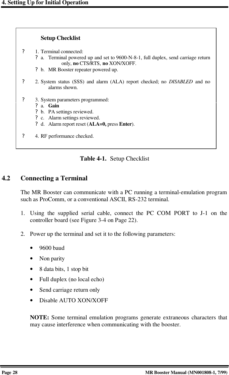
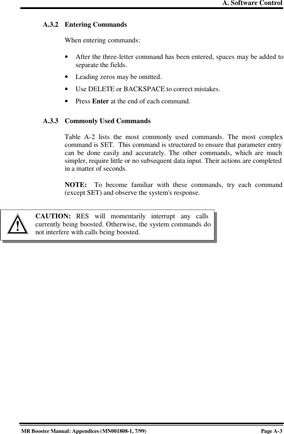
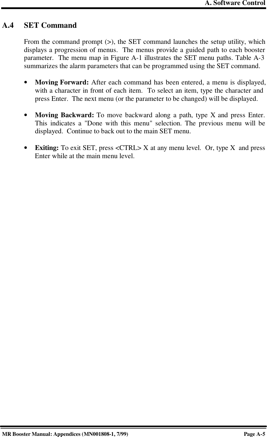
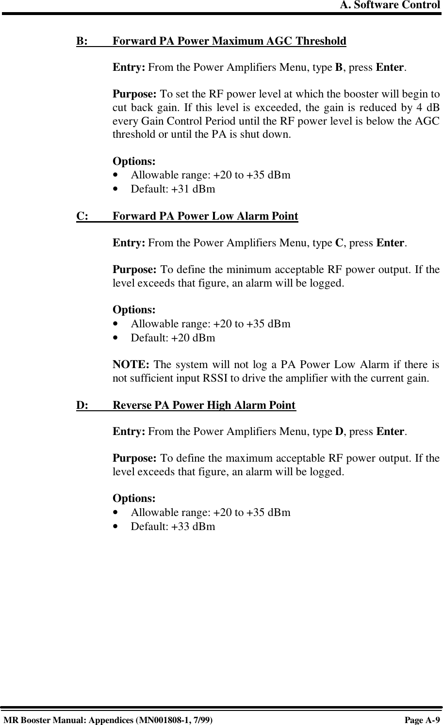
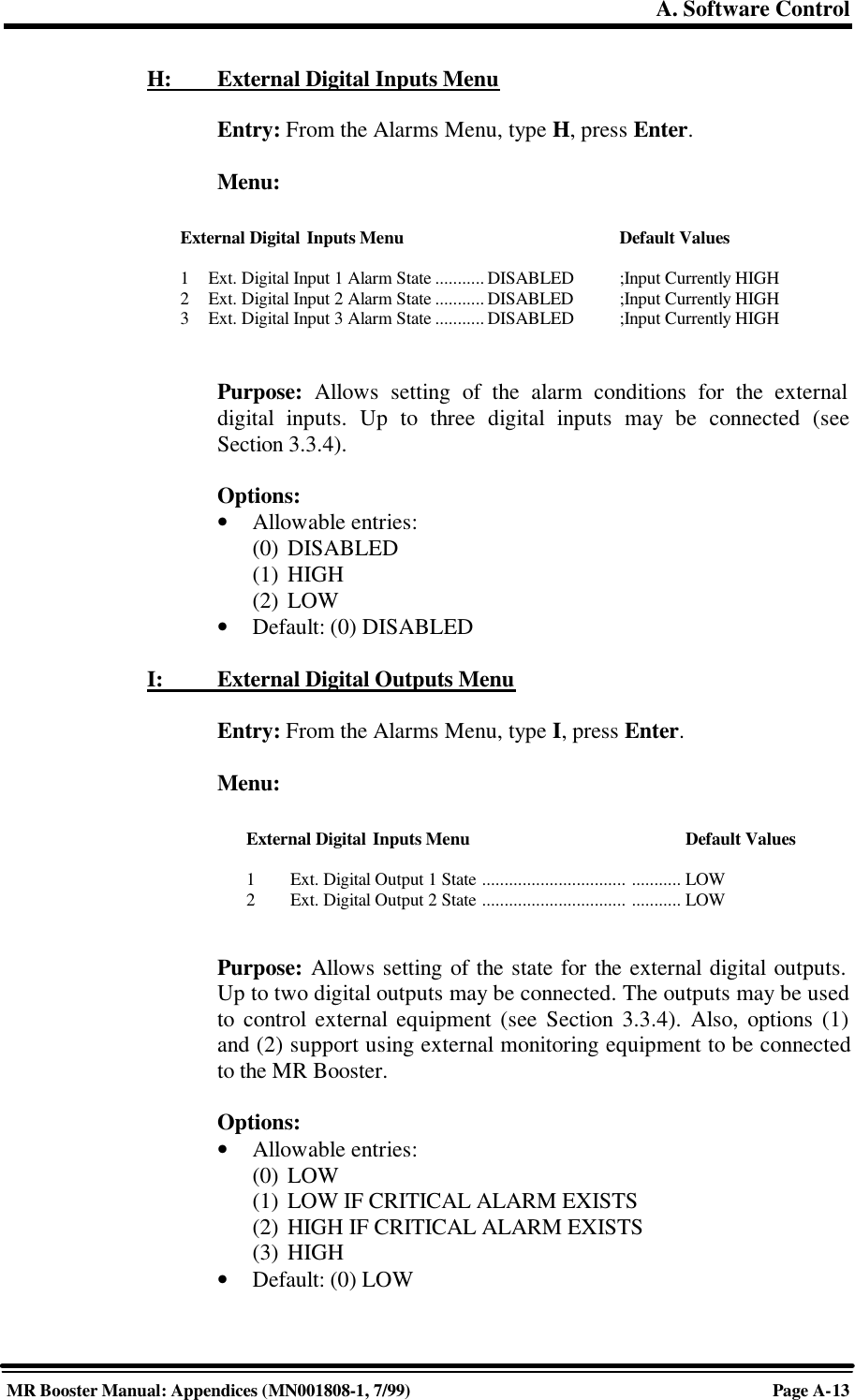
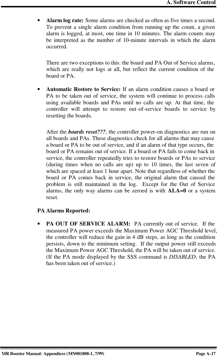
![A. Software ControlPage A-2MR Booster Manual: Appendices (MN001808-1, 7/99)3. Power up the MR Booster. After about two seconds, the terminal should respondwith a welcome message.• If the response is garbled, check the terminal setup.• If there is no response, turn the booster OFF, then ON again. If there is stillno response, turn the unit OFF. Recheck the power hookup and the terminalhookup and configuration.A.3 Basic CommandsFollowing are basic rules and key commands for use with the MR Booster operatingsoftware.Symbol Definition><CTRL><ESC>Command Prompt. The system uses this prompt character to indicateit is ready to accept commands.Control Key. Used in combination with other keys.Escape Key. Escape is a single key marked ESC on most keyboards.Table A-1. Command DefinitionsA.3.1 SyntaxSystem commands consist of three letters followed by a maximum of threedata fields, as follows:COM [FIELD 1 -] [FIELD 2 =] [FIELD 3] Enter• COM: Three-letter command.• FIELD 1: Up to four hex characters followed by a dash (-).• FIELD 2: Up to four hex characters followed by an equal (=) sign.• FIELD 3: Up to two hex characters.• Enter: Press enter at the end each command.NOTE: Few commands require entry of data fields. After a command hasbeen entered, the system will prompt for data it needs. The system will ignoreunneeded data fields.](https://usermanual.wiki/Andrew-Wireless-Innovations-Group/MRB-CELL/User-Guide-53920-Page-52.png)
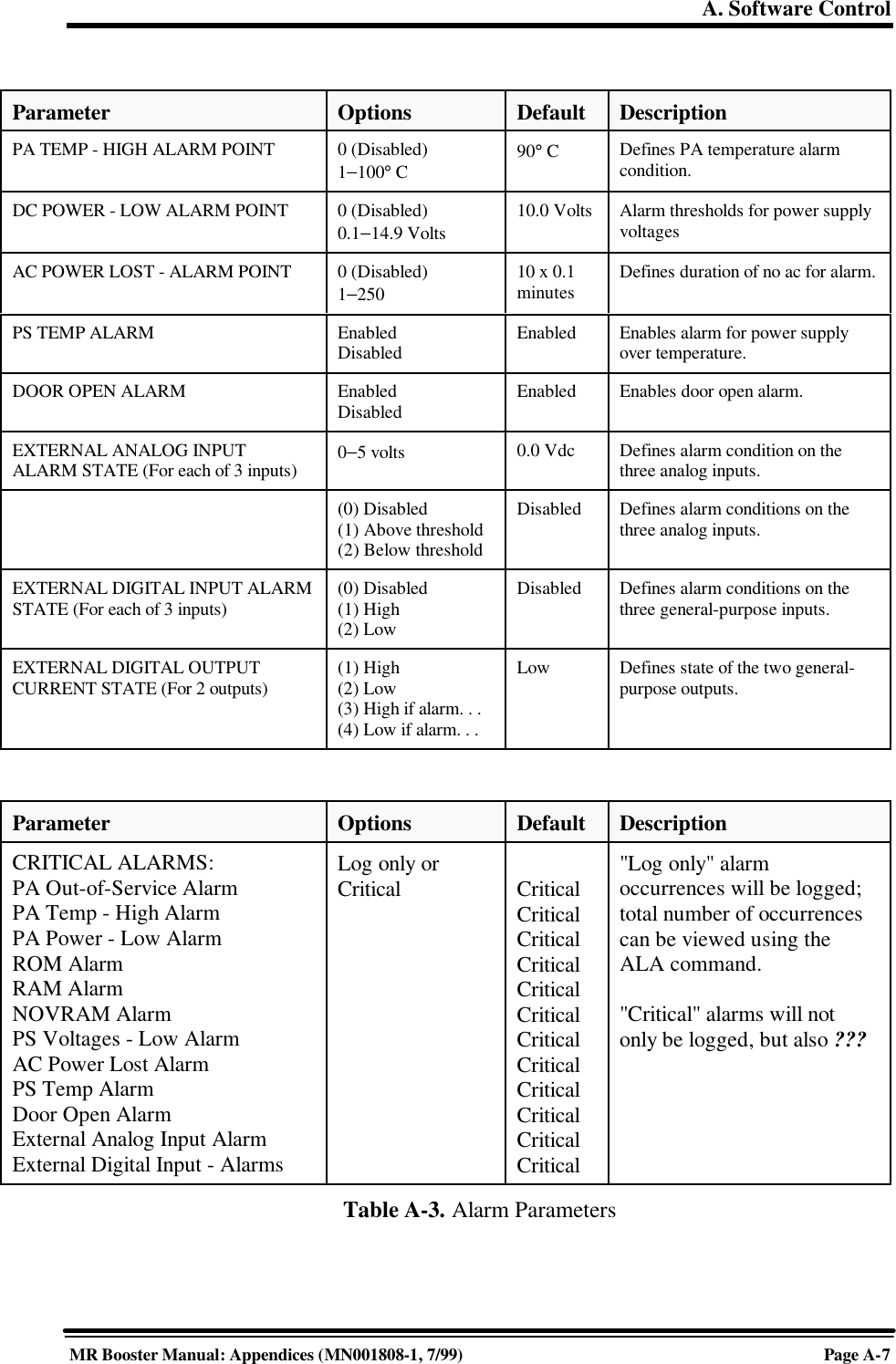
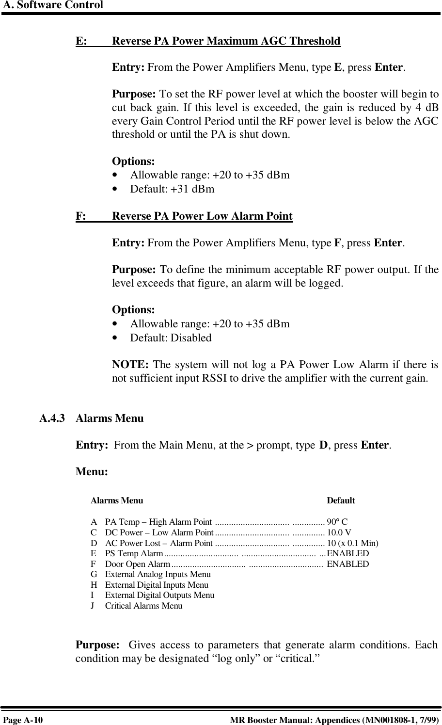
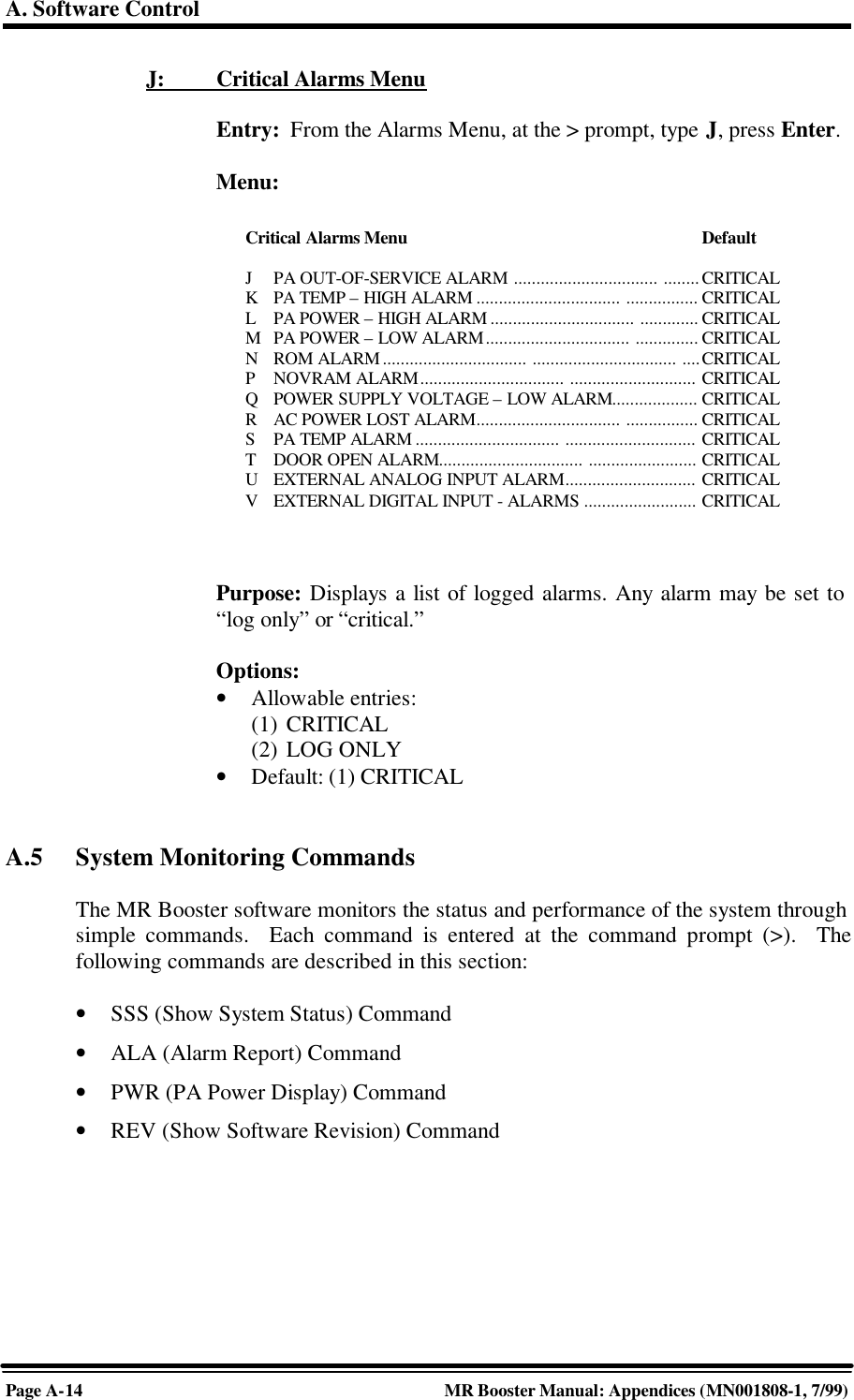
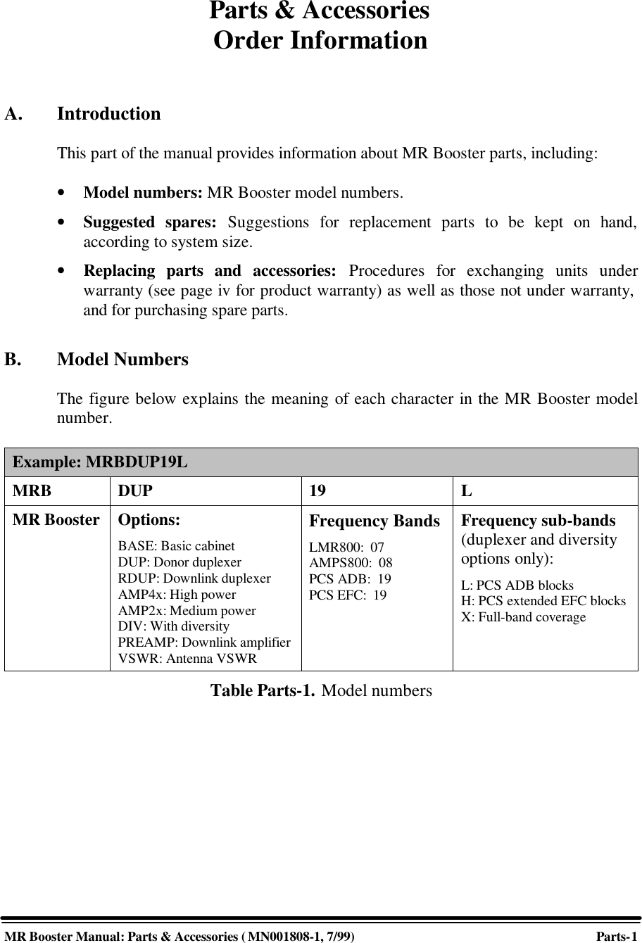
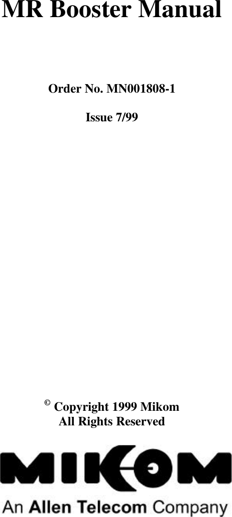
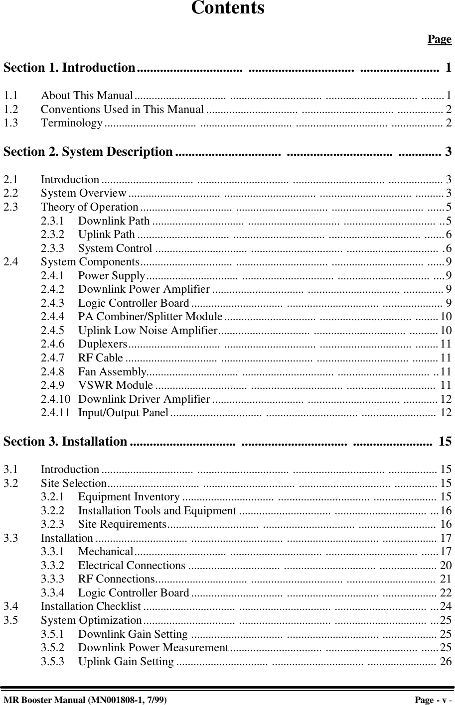
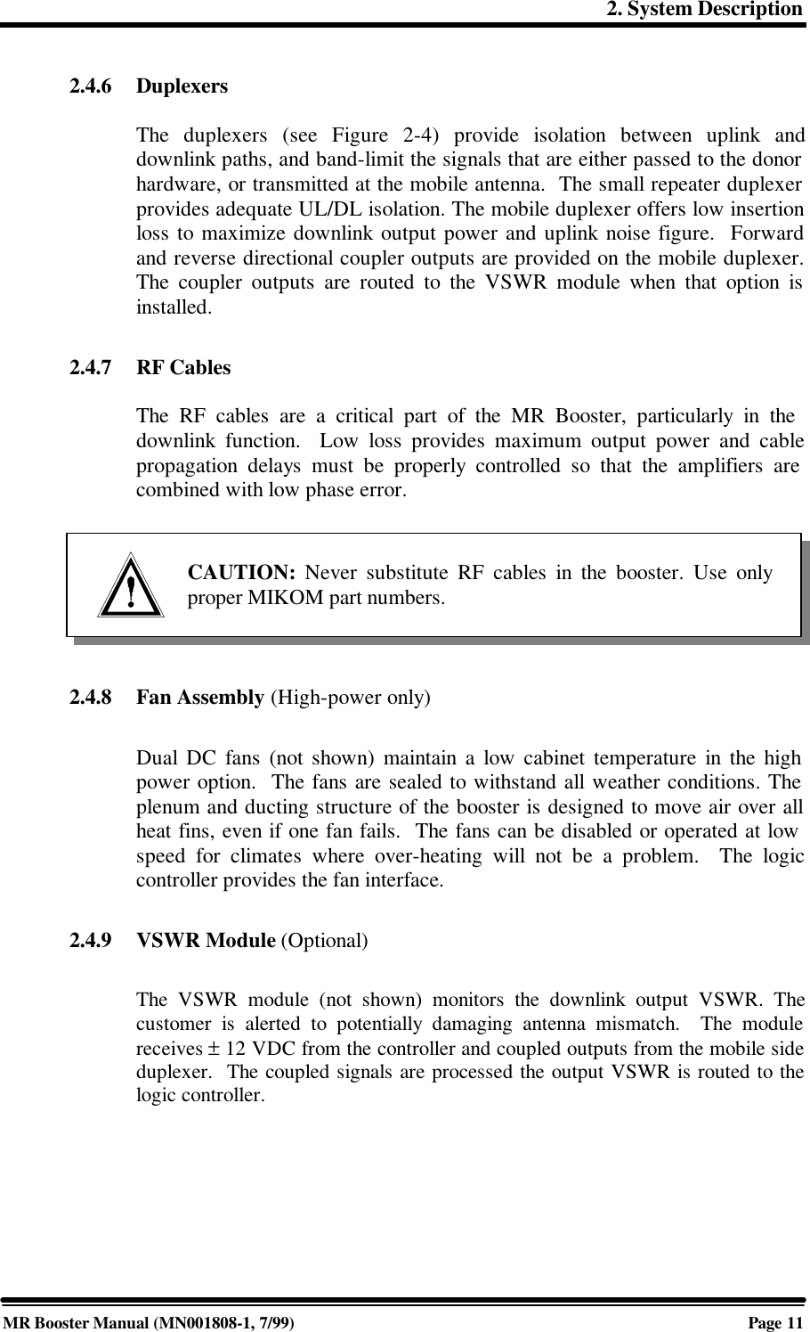
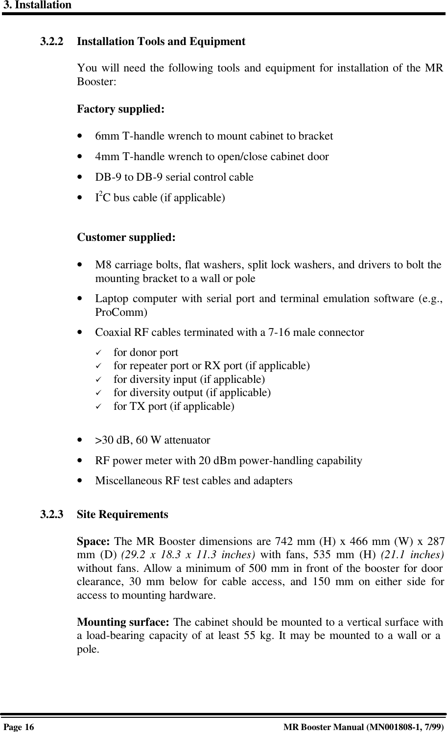
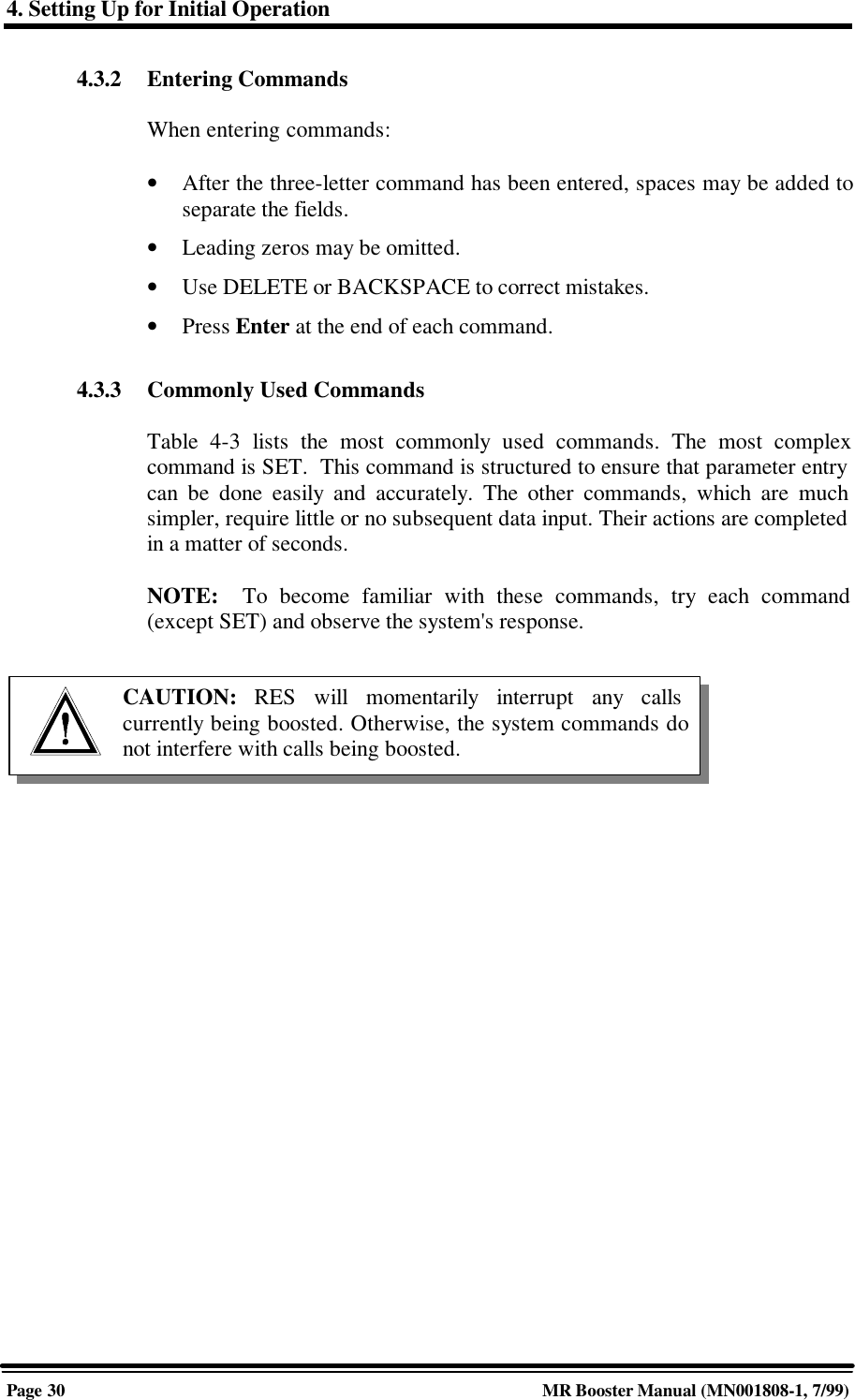
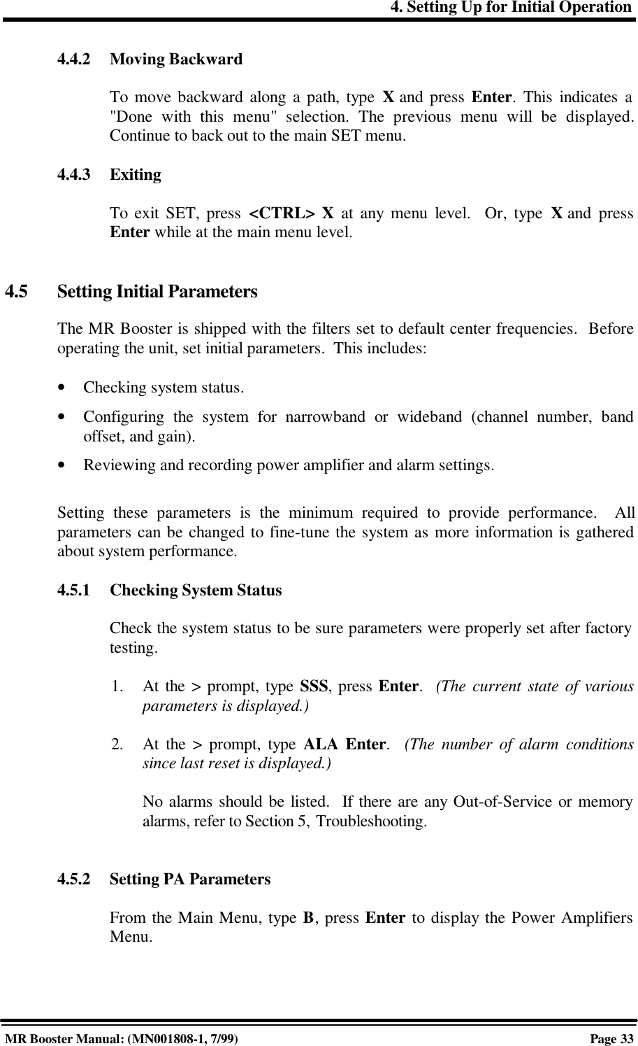
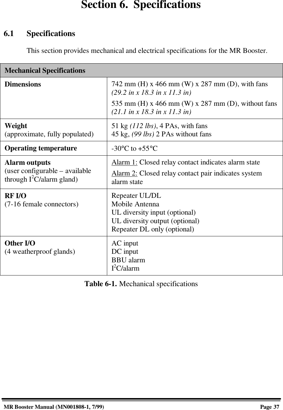
![A. Software ControlPage A-18 MR Booster Manual: Appendices (MN001808-1, 7/99)When a PA goes out of service, the MR Booster will attempt to bring itback into service by re-initializing the RF hardware, including theboards??? and the PAs. Because an out-of-service PA is usually due toan oscillation condition, the system does not attempt immediately to bringit back. Rather, the system will attempt a restore-to-service once eachhour, as long as the PA continues to go back out of service. After sevensuch attempts, the system will discontinue restore-to-service attempts tothat PA, leaving it out of service. However, if another board or PA goesout of service, it will trigger its own set of restarts, any of which mightbring back any or all out-of-service boards or PAs.• PA TEMP HIGH ALARM: PA temperature above the Maximum PATemperature Alarm Point parameter.• PA POWER HIGH ALARM: PA output power above the MaximumPower Alarm Point parameter. Following is a list of possible causes:ü Improper setting of the PA Power High Alarm Point with respect tothe PA Power AGC Thresholdü Failure of the AGC algorithm to keep the power in checkü Too much gainü Oscillation• PA POWER LOW ALARM: PA output power below the MinimumPower Alarm Point parameter at a time when RSSI and gain are sufficientto cause that much power. Following is a list of possible causes:ü PA failureü Board failure (either low gain or inaccurate RSSI reporting)ü Problem with one of the RF cables that couple the boards and PAsSystem Alarm Conditions Reported:• ROM ALARM: Problem in Read Only Memory. (Checked at power-upby computing a ROM checksum and comparing it with a storedchecksum. Note: The CHK command will recompute the ROM checksumand display the stored checksum but will not check for a match.)• NOVRAMALARM: Problem in Nonvolatile Memory. (Checked atpower-up by looking for several "signature bytes" that indicate if datahave ever been written and if gross memory loss has occurred. If thesignature cannot be found, the system tries to write the defaults [and thesignature] to the NOVRAM.ü Alarm readings:0 = No problems.](https://usermanual.wiki/Andrew-Wireless-Innovations-Group/MRB-CELL/User-Guide-53920-Page-68.png)