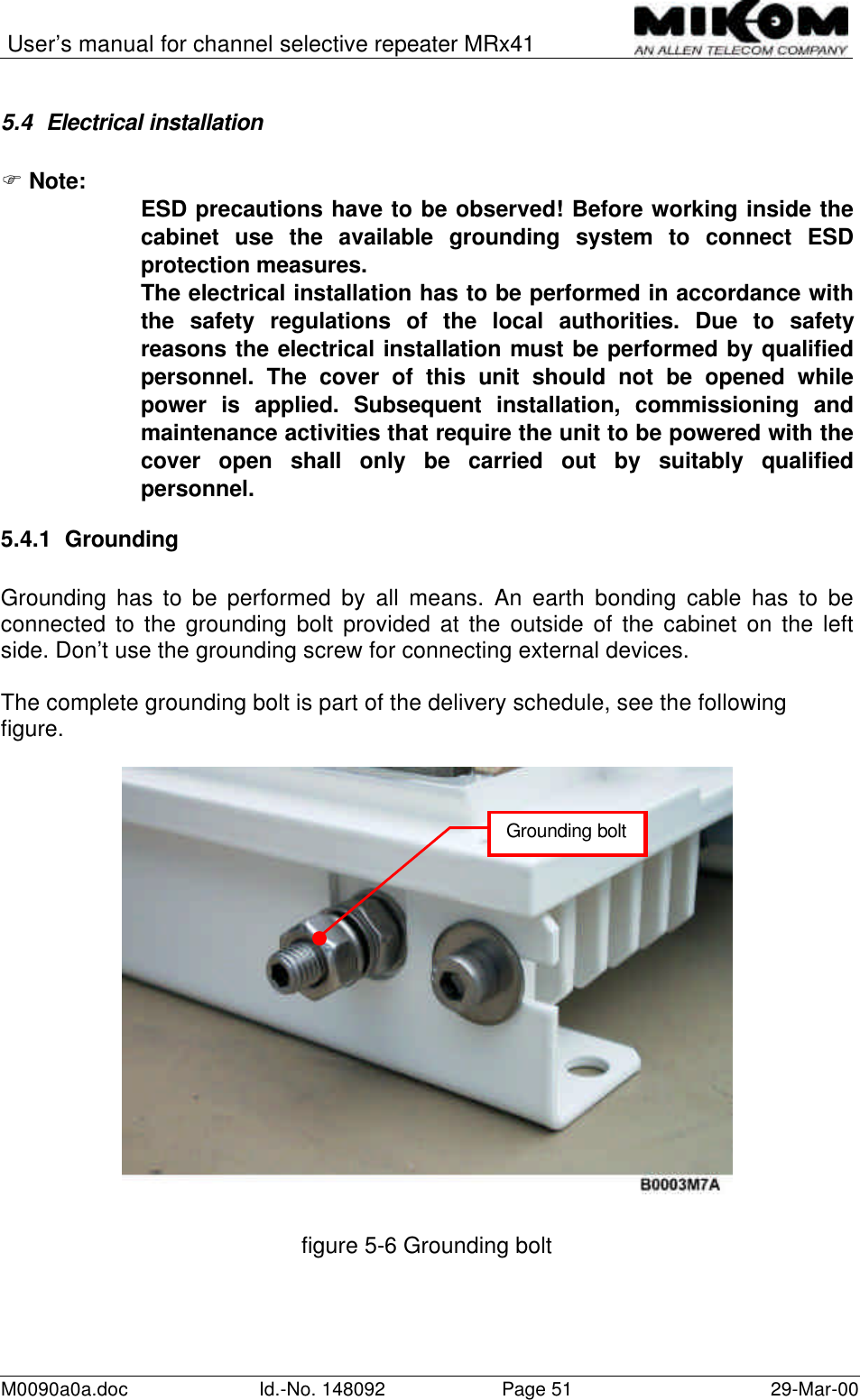
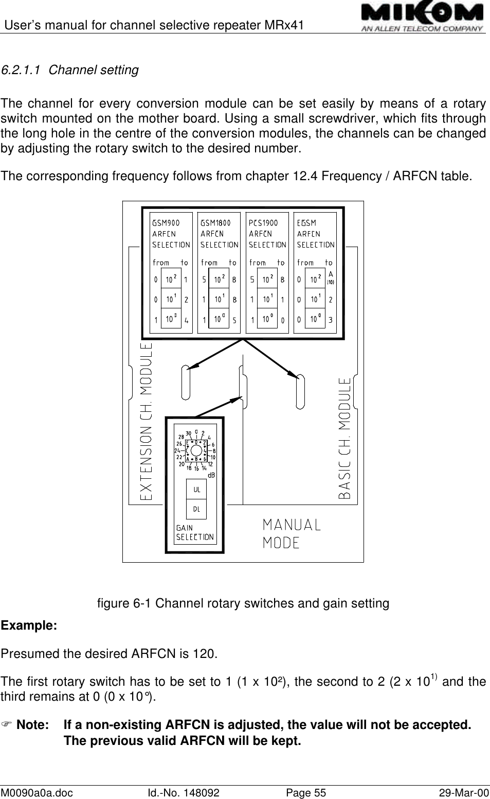
Andrew Wireless Innovations Group RPT-MR741 GSM channel selective repeater User Manual M0090a0a
Andrew Wireless Innovations Group GSM channel selective repeater M0090a0a
UserManual.wiki
>
Andrew Wireless Innovations Group
>
RPT-MR741 User Manual
>
User Manual
Contents
1.
User Manual
2.
Antenna mounting information
User Manual
Navigation menu
Upload a User Manual
Namespaces
Wiki Guide
HTML
PDF
Info
Views
User Manual
Discussion / Help
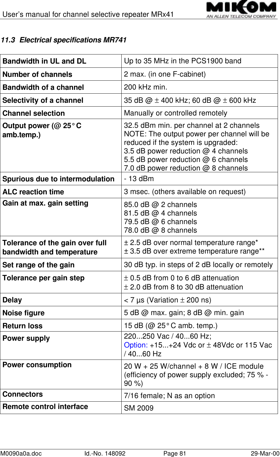
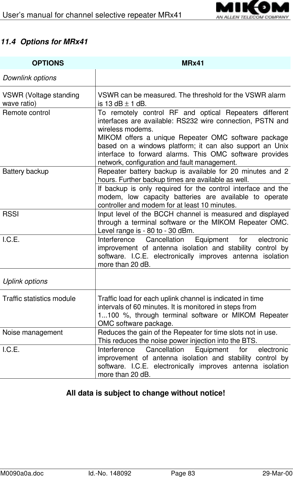
Navigation
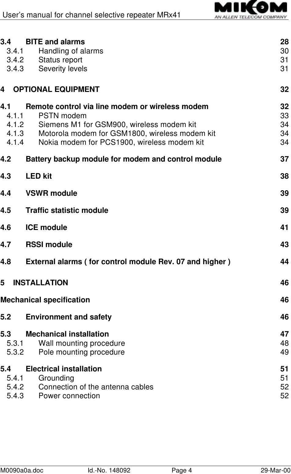
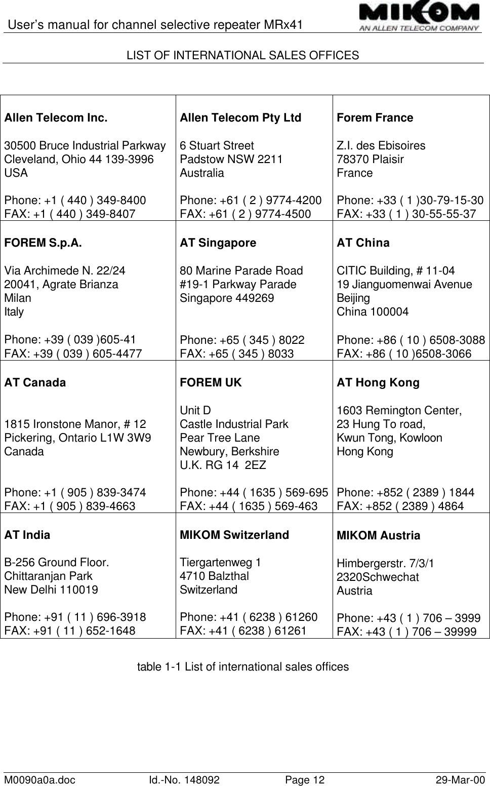
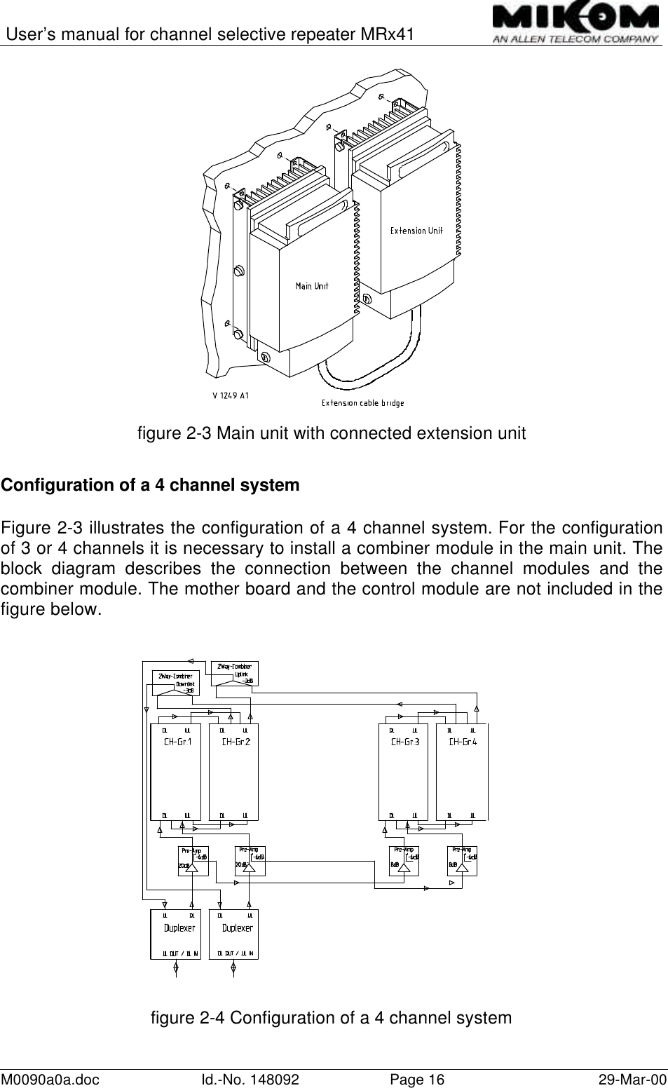
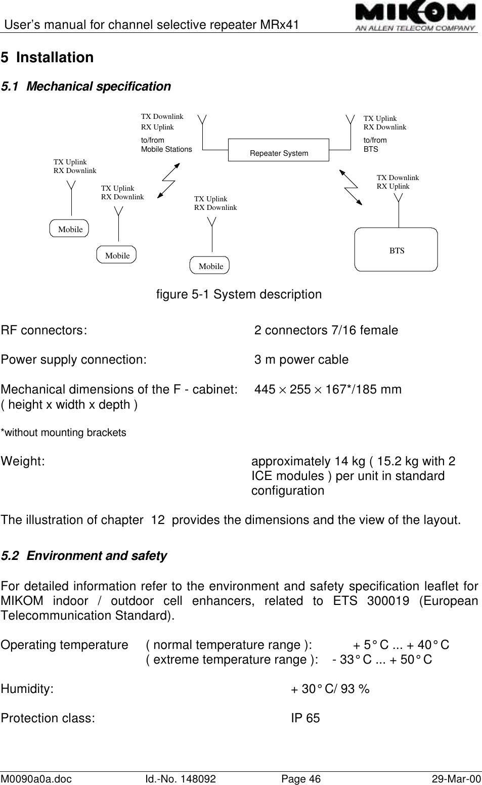
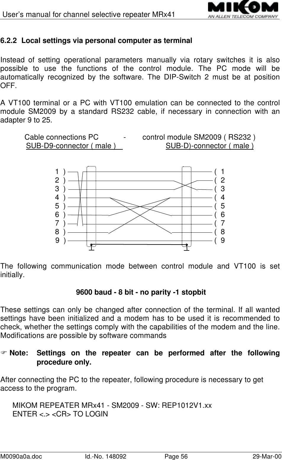
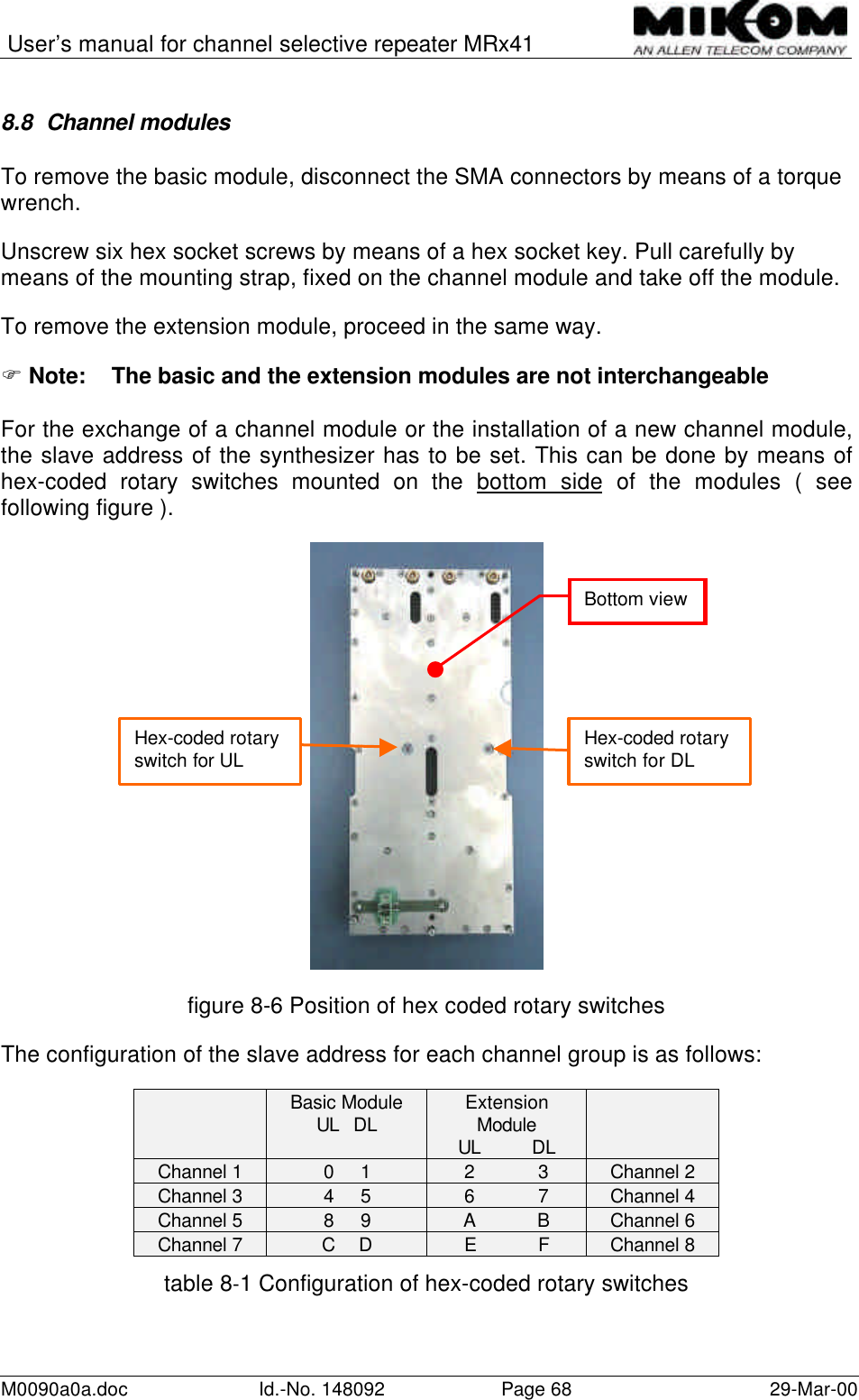
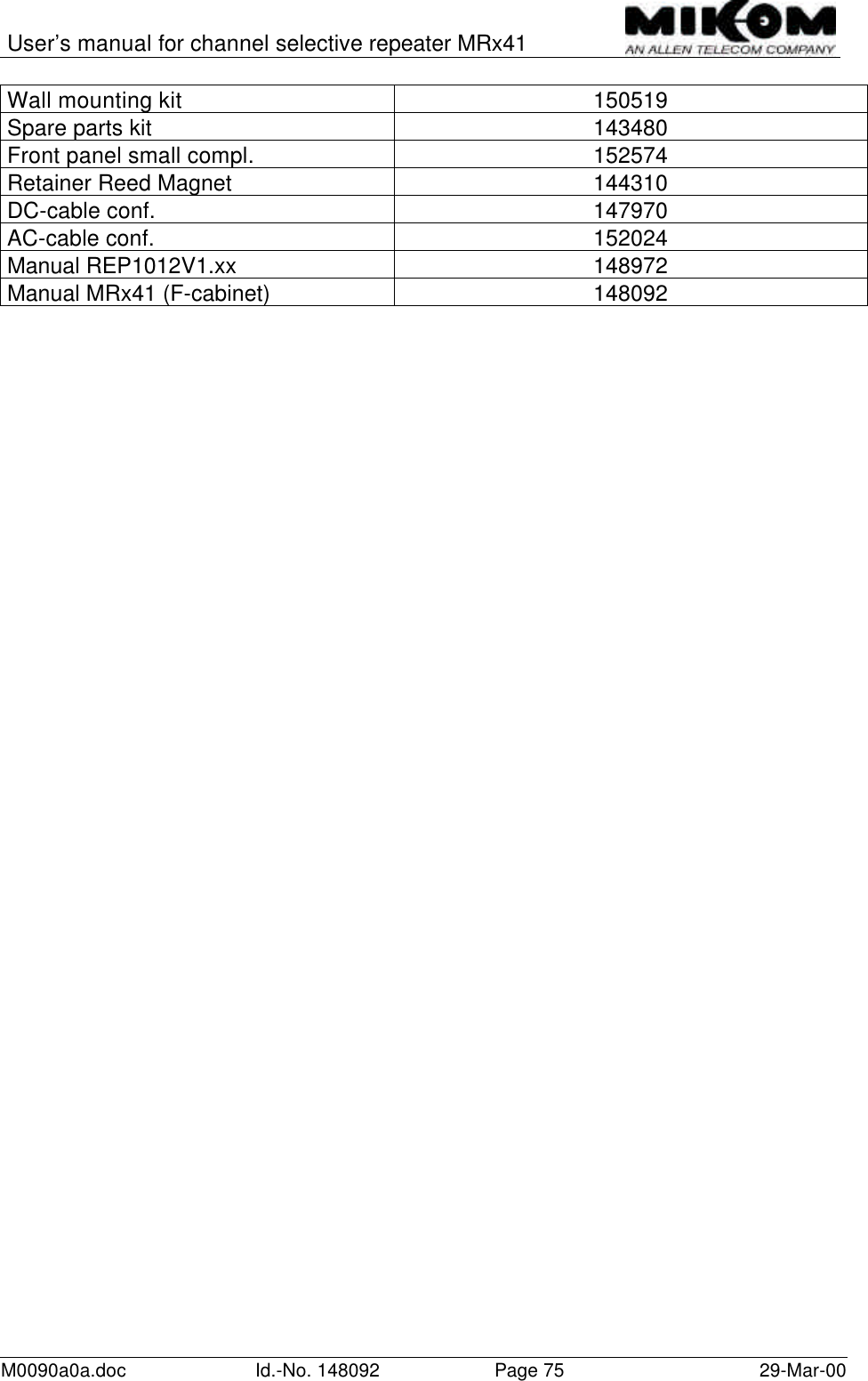
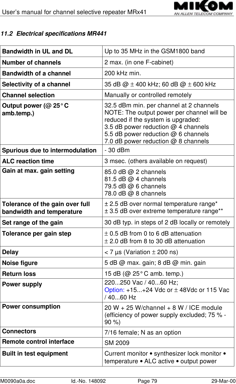
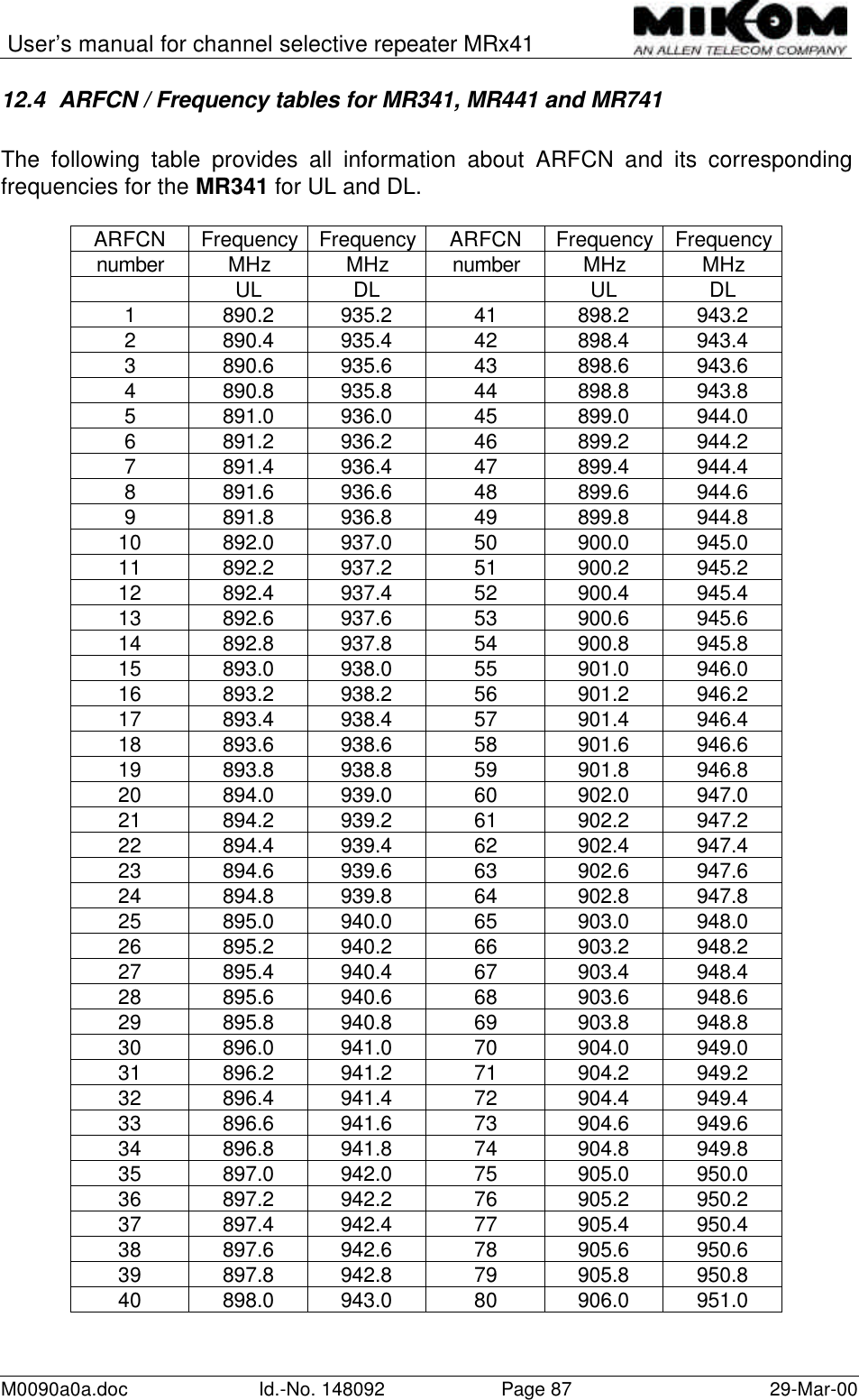
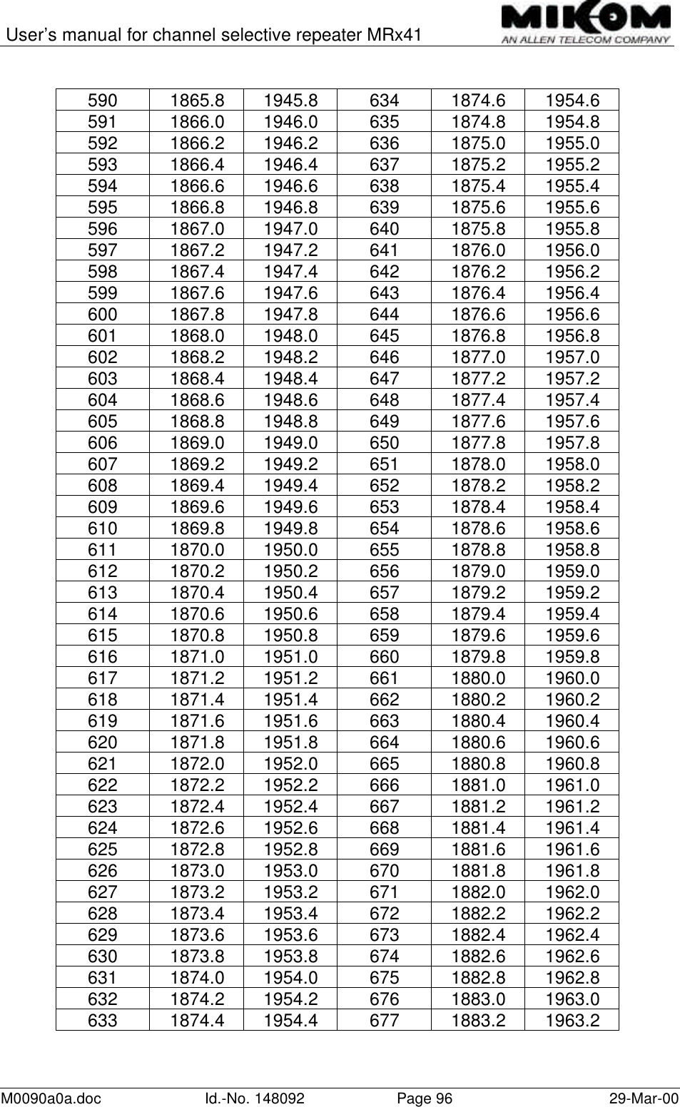
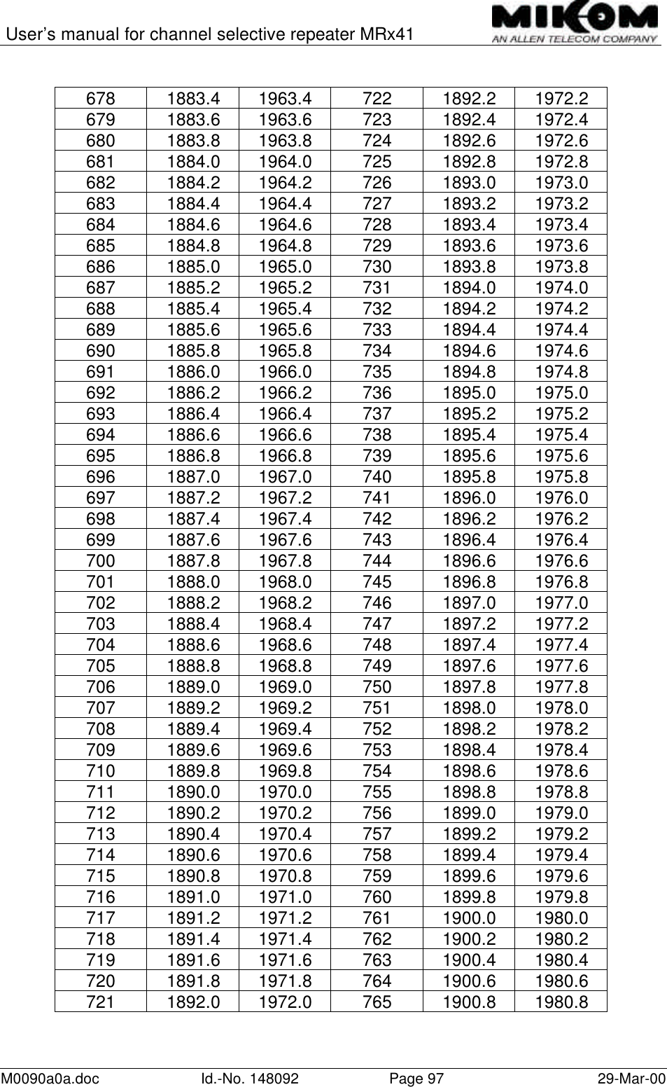
![User’s manual for channel selective repeater MRx41M0090a0a.doc Id.-No. 148092 Page 42 29-Mar-00The following table is valid for a velocity factor of 0.88 representing standard coaxialcable with foam dielectric ( e.g. 1/2”, 7/8” ).AS*[m] 2 4 6 8 10 12 14 16 18 20 22 24 26 DelayoptionCL*[m] 8.0-34.46.2-32.66.0-30.98.0-29.110.0-27.412.0-25.614.0-23.816.0-22.118.0-20.3 ----270ns34.4-60.832.6-59.030.9-57.329.1-55.527.4-53.825.6-52.023.8-50.222.1-48.520.3-46.720.0-45.022.0-43.224.0-41.426.0-39.7370ns60.8-87.259.0-85.457.3-83.755.5-81.953.8-80.252.0-78.450.2-76.648.5-74.946.7-73.145.0-71.443.2-69.641.4-67.839.7-66.1470ns>87.2 >85.4 >83.7 >81.9 >80.2 >78.4 >76.6 >74.9 >73.1 >71.4 >69.6 >67.8 >66.1 570nsThe following table is valid for a velocity factor of 0.66 representing standard coaxialcable with PE / PU dielectric ( e.g. RG223, RG8, RG214, RG58 ).AS*[m] 2 4 6 8 10 12 14 16 18 20 22 24 26 DelayoptionCL*[m] 6.0-25.84.7-24.56.0-23.28.0-21.810.0–20.512.0–19.214.0–17.916.0–16.6-----270ns25.8–45.624.5–44.323.2–43.021.8–41.620.5–40.319.2–39.017.9–37.716.6–36.418.0–35.020.0–33.722.0–32.424.0–31.126.0–29.8370ns45.6–65.444.3–64.143.0–62.841.6–61.440.3–60.139.0–58.837.7–57.536.4–56.235.0–54.833.7–53.532.4–52.231.1–50.929.8–49.6470ns>65.4 >64.1 >62.8 >61.4 >60.1 >58.8 >57.5 >56.2 >54.8 >53.5 >52.2 >50.9 >49.6 570ns](https://usermanual.wiki/Andrew-Wireless-Innovations-Group/RPT-MR741.User-Manual/User-Guide-106498-Page-42.png)