Andrew Wireless System CAPL17E19 ION-E Remote Unit for cellular systems User Manual
Andrew Wireless System ION-E Remote Unit for cellular systems
User Manual
ION®-E Series Low Power Carrier Access Point
Installation Guide • M0201AAC • February 2018

DISCLAIMER
ThisdocumenthasbeendevelopedbyCommScope,andisintendedfortheuseofitscustomersandcustomersupport
personnel.Theinformationinthisdocumentissubjecttochangewithoutnotice.Whileeveryefforthasbeenmadeto
eliminateerrors,CommScopedisclaimsliabilityforanydifficultiesarisingfromtheinterpretationoftheinformation
containedherein.Theinformationcontainedhereindoesnotclaimtocoveralldetailsorvariationsinequipment,norto
provideforeverypossibleincidenttobemetinconnectionwithinstallation,operation,ormaintenance.Thisdocument
describestheperformanceoftheproductunderthedefinedoperationalconditionsanddoesnotcovertheperformance
underadverseordisturbedconditions.Shouldfurtherinformationbedesired,orshouldparticularproblemsarisewhichare
notcoveredsufficientlyforthepurchaser'spurposes,contactCommScope.
CommScopereservestherighttochangeallhardwareandsoftwarecharacteristicswithoutnotice.
COPYRIGHT
©2018CommScope,Inc.AllRightsReserved.
Thisdocumentisprotectedbycopyright.Nopartofthisdocumentmaybereproduced,storedinaretrievalsystem,or
transmitted,inanyformorbyanymeans,electronic,mechanicalphotocopying,recording,orotherwisewithouttheprior
writtenpermissionofCommScope.
Forpatentsseewww.cs-pat.com.
TRADEMARKS
Alltrademarksidentifiedby®or™areregisteredtrademarksortrademarks,respectively,ofCommScope,Inc.Namesof
otherproductsmentionedhereinareusedforidentificationpurposesonlyandmaybetrademarksand/orregistered
trademarksoftheirrespectivecompanies.
AndrewWirelessSystemsGmbH,19-December-2017

M0201AAC ION®-E Series Low Power Carrier Access Point Installation Guide
© February 2018 CommScope, Inc. Page iii
TABLE OF CONTENTS
Document Overview .................................................................................................................................................................................. 1
Document Revision History ..............................................................................................................................................................................1
Document Cautions and Notes......................................................................................................................................................................... 2
Abbreviations Used in this Guide ..................................................................................................................................................................... 2
CommScope Part Numbers .............................................................................................................................................................................. 2
ION-E Series System Overview................................................................................................................................................................... 3
CAP L Overview ......................................................................................................................................................................................... 4
CAP L Connectors, Ports, and LEDs................................................................................................................................................................... 5
CAP L with an Optical Fiber Interface......................................................................................................................................................... 6
CAP L with a Copper Interface and External DC Power..............................................................................................................................7
CAP L with a Copper Interface and Power Cat6A Cable............................................................................................................................. 8
Fan Interface Port.......................................................................................................................................................................................9
CAP L Accessory Options ..................................................................................................................................................................................9
Fan Kit....................................................................................................................................................................................................... 10
Flat Mounting Bracket Kit......................................................................................................................................................................... 10
CAP L Mounting Bracket Kit .....................................................................................................................................................................10
CAP L Hybrid Fiber Splice Box Kit.............................................................................................................................................................. 11
AC/DC Power Supply Kit........................................................................................................................................................................... 11
OCTIS Kits .................................................................................................................................................................................................11
Safely Working with ION-E Hardware ...................................................................................................................................................... 12
Health and Safety Precautions .................................................................................................................................................................12
Property Damage Warnings ..................................................................................................................................................................... 12
General Installation Safety Requirements ............................................................................................................................................... 12
Guard Against Damage from Electro-Static Discharge.............................................................................................................................13
Compliance............................................................................................................................................................................................... 13
Equipment Symbols Used / Compliance .................................................................................................................................................. 15
Installing CAP Ls....................................................................................................................................................................................... 16
Prepare for Installation................................................................................................................................................................................... 16
Required Distances Between CAP Ls and Antennas ....................................................................................................................................... 16
CAP L Installation Rules .................................................................................................................................................................................. 16
Cascade Rules .................................................................................................................................................................................................17
Recommended Tools and Material .......................................................................................................................................................... 18
Determine the Power Consumption of the CAP L .................................................................................................................................... 18
Determine the CAP L Mounting Site ........................................................................................................................................................19
General Mounting Cautions .....................................................................................................................................................................21
Unpack and Inspect the CAP L and Optional Accessories ........................................................................................................................22
Mount the CAP L.............................................................................................................................................................................................22
Flat-Surface Mount a CAP L...................................................................................................................................................................... 23
Wall Mount a CAP L.................................................................................................................................................................................. 24
Mounting Orientation for Wall Mounts.............................................................................................................................................24
Wall Mount a CAP L Using a Flat Mounting Bracket Kit.....................................................................................................................26
Wall Mount a CAP L Using a CAP L Hybrid Fiber Splice Box Kit.......................................................................................................... 28
Wall Mount a CAP L Using a AC/DC Power Supply Kit ....................................................................................................................... 32
Ceiling Mount a CAP L .............................................................................................................................................................................. 35
Ceiling Mount a CAP L without a Fan Kit............................................................................................................................................35
Ceiling Mount a CAP L with a Fan Kit .................................................................................................................................................35
(Optional) Ground the CAP L .......................................................................................................................................................................... 36
Connect the CAP L Cables............................................................................................................................................................................... 37
Cable a CAP L with an Optical Fiber Interface .......................................................................................................................................... 37
Cable a CAP L with a Copper Interface.....................................................................................................................................................40
Cat6A Cable Requirements for CAP Ls with a Copper Interface ........................................................................................................ 40
Cable a CAP L with a Copper Interface and External DC Power.........................................................................................................43
Cable a CAP L with a Copper Interface and Power over Cat6A Cable................................................................................................ 45
Powering a CAP L ............................................................................................................................................................................................ 48
Power LED Behavior .................................................................................................................................................................................48
Using the Power-Down Button ................................................................................................................................................................48
CAP L Maintenance.................................................................................................................................................................................. 49
Remove a CAP L from a Wall or Ceiling Mount .............................................................................................................................................. 49
Preventative CAP L Maintenance for CAP Ls with the Fan Kit Option............................................................................................................ 49
Cat6A Specifications and Testing Requirements....................................................................................................................................... 50

ION®-E Series Low Power Carrier Access Point Installation Guide M0201AAC
Page iv © February 2018 CommScope, Inc.
Table of Contents
Contacting CommScope ........................................................................................................................................................................... 51
DCCS Global Technical Support ...................................................................................................................................................................... 51
Telephone Helplines.................................................................................................................................................................................51
Online Support ......................................................................................................................................................................................... 51
Waste Electrical and Electronic Equipment Recycling....................................................................................................................................51
Hardware to Software Mapping Information.................................................................................................................................................52
DCCS Technical Training ................................................................................................................................................................................. 52
Accessing ION-E Series User Documentation .................................................................................................................................................53
M0201AAC ION®-E Series Low Power Carrier Access Point Installation Guide
© February 2018 CommScope, Inc. Page 1
DOCUMENT OVERVIEW
ThisinstallationguideprovidesaproductoverviewandinstallationinstructionsfortheION-ESeriesLow
PowerCarrierAccessPoint(CAPL),whichallowstransmissionbetweenION-Eequipment,antennas,and
Ethernetdevices(suchasWiFiandIPcameras).
Table1liststheCAPLmodelsthatthisinstallationguidesupports.
Document Revision History
ThisisthethirdreleaseoftheION®-ESeriesLowPowerCarrierAccessPointInstallationGuide,CommScope
DocumentNumberM0201AAC,datedJanuary2018,which
•adds
–supportfortheCAPL17E/19/23/25TDD
–"RequiredDistancesBetweenCAPLsandAntennas”onpage16
•updates
–therequiredclearancebetweenaCAPLandanantennain"GeneralInstallationSafetyRequirements”
onpage12
–“AntennaStmtforISED:”and“AntenneStmtpourISDE:”onpage14.
Table 1. Supported CAP L Models
Part Number 1 Model Name
7770203-000x CAP L 17E/17E/23/23
7770209-000x CAP L 18/21/26/26
7770356-000x CAP L 17E/17E/19/19
7776596-000x CAP L 7/80-85/17E/19
7776597-000x CAP L 17E/19/23/25TDD
1 The “-000x” suffix provides information as to whether the CAP L has a Fiber or
Copper interface, and the power and Fan Kit options. Contact your local sales
representative for further information.
For further information on ION-E system components, refer to the ION-E Series WCS-2, WCS-4, and e-POI
Subracks and Power Supply Unit Installation Guide and the ION-E Series Universal Access Point Installation
Guide (see "Accessing ION-E Series User Documentation” on page 53.)
For information on how to find the minimum software requirements for ION-E hardware, refer to
"Hardware to Software Mapping Information” on page 52.
ION®-E Series Low Power Carrier Access Point Installation Guide M0201AAC
Page 2 © February 2018 CommScope, Inc.
Document Overview
Document Cautions and Notes
Thisdocumentcontainsnotes,cautions,andwarnings.Ingeneral,cautions,warnings,andnotesindicatethe
following:
Abbreviations Used in this Guide
CommScope Part Numbers
TheCommScopeION-Epartnumbersinthisinstallationguideareintheformatofnnnnnnn-xx,wherethe
“-xx”suffixindicatesthelatestrelease.ContactyourlocalCommScopesalesrepresentativeforthecurrent
releasepartnumber.
The icon to the left is used to indicate a caution or warning. Cautions and warnings indicate operations or
steps that could cause personal injury, induce a safety problem in a managed device, destroy or corrupt
information, or interrupt or stop services.
The icon to the left indicates a caution or warning that pertains to laser equipment.
The icon to the left is indicates a caution or warning that pertains to Radio Frequency (RF).
The icon to the left indicates that the hardware is susceptible to Electro-Static Discharge (ESD) damage.
The icon to the left is indicates a Note. Notes provide information about special circumstances.
AUX Auxiliary ISDE Innovation, Sciences et Développement économique Canada
CCelsius ISED Innovation, Science and Economic Development Canada
CAN Central Area Node kg Kilogram
CAP L Carrier Access Point, Low Power LED Light Emitting Diode
Cat Category MHz Megahertz
CAT Copper Transport mm Millimeter
dB Decibel MMF Multi-Mode Fiber
dBm Decibel-milliwatts OPT Optical Transport
DC Direct Current PN Part Number
DCCS Distributed Coverage and Capacity Solutions RAN Regional-Area Network
EFTA European Free Trade Association RF Radio Frequency
EMC Electromagnetic Compatibility RU Rack Unit
EME
A
Europe, Middle East, Africa SFP Small Form-Factor Pluggable
EU European Union SMF Single-Mode Fiber
FFahrenheit TEN Transport Expansion Node
FCC Federal Communications Commission UAP Universal Access Point
Gb Gigabyte Vdc Volts, direct current
GHz Gigahertz WWatts
M0201AAC ION®-E Series Low Power Carrier Access Point Installation Guide
© February 2018 CommScope, Inc. Page 3
ION-E Series System Overview
ION-E SERIES SYSTEM OVERVIEW
ThissectiondescribestheION-Esystem,whichisaunifiedwirelessinfrastructureplatformdefinedaround
ITbasedarchitecture.Itbringstogetherlicensedwirelessandpower,plusGigabitEthernetforWiFiintoone
wirelesssystemthatcanscaletobuildingsizeandistechnologyandspectrumagnosticandadaptive.Abasic
ION-Esystemcomprisesthecomponentslistedbelow;seealsoFigure1.
•CentralAreaNode(CAN)—providesserver-levelcontrolandprimarysignaldistribution.WCS-2(2U)
andWCS-4(4U)Subrackoptionsareavailable.
•TransportExpansionNode(TEN)—connectstoaCANusingMulti-ModeorSingle-Modefiberasa
secondarydistributionpoint.WCS-2(2U)andWCS-4(4U)Subrackoptionsareavailable.
•AccessPoint—connectsaCANoraTENtoantennasorotherwirelessdevices.Onthedownlink,an
AccessPoint(AP)convertsdataarrivingattheAPtoanalogsignalsandsendsthemtoanantenna.Onthe
uplink,receivedsignalsaredigitizedandserializedintodatastreamswhicharesentbacktothe
CAN/TEN.EachAPcontainsuptofourtransceiverpathsforRFcoverage.APssupportsGigabitEthernet
forWiFi,IPcameras,orotherdevicesinadditiontowirelessoveracommoncable.AnAPcanbeanyof
thefollowing:
–UniversalAccessPoint(UAP)—connectstheCAN/TENtoaninternalantenna;receivesdataand
powerthroughCat6Atwistedpaircabling.
–UAP-X—similarinfunctionasthestandardUAP,inadditiontoCommercialfrequencies,theUAP-X
alsosupportsPublicSafetyfrequencies,including700,800and400MHz.TheUAP-Xconnectsthe
CAN/TENtoexternalantennasandsupportsanextensivefrequencyrange.
–UAP-N25andUAP-XN25—similarinfunctionastheUAPandUAP-X,theUAP-N25andUAP-XN25
featurea25MHzfilterononepath(insteadofthe80MHzfilteronaUAPorUAP-X).Thisallows
coexistenceofspecificbands,suchasAustralia850MHzand900MHz.
–LowPowerCarrierAccessPoint(CAPL)—interfaceswiththeCAN/TENviaaCat6Acableoran
opticallink.ThisallowstheCAPLtoprovidedataoverCopper,Single-ModeFiber(SMF),or
Multi-ModeFiber(MMF).PowerforCAPLswithaCopperInterfacecanbeprovidedoverCat6Aor
ExternalAC/DC.PowerforCAPLswithaFiberInterfaceisprovidedoverExternalAC/DCorremotely
throughhybridfiber.
Figure 1. Basic ION-E System
A WCS-2 and a WCS-4 can be configured for use as a CAN or a TEN. When the information in this guide
applies to both configurations, the term “CAN/TEN” is used. When the information pertains to only one
of the configurations, that configuration will be identified singularly as “CAN” or “TEN.”
CAN TEN WiFi IP CameraAccess Point MM/SM FiberCat6A
ION®-E Series Low Power Carrier Access Point Installation Guide M0201AAC
Page 4 © February 2018 CommScope, Inc.
CAP L Overview
CAP L OVERVIEW
TheLowPowerCarrierAccessPoint(CAPL)interfaceswiththeCAN/TENviaaCat6Acableoranopticallink.
ThisallowstheCAPLtoprovidedataoverCopper,Single-ModeFiber(SMF),orMulti-ModeFiber(MMF).
PowerforCAPLswithaCopperInterfacecanbeprovidedoverCat6AorexternalDC.PowerforCAPLswith
aFiberInterfaceisprovidedoverExternalAC/DCorremotelythroughhybridfiber.
Onthedownlink,theCAPLconvertsdataarrivingattheCAPLtoanalogsignalsandsendsthemtothe
Antennaports.Ontheuplink,receivedsignalsaredigitizedandserializedintodatastreams,whicharesent
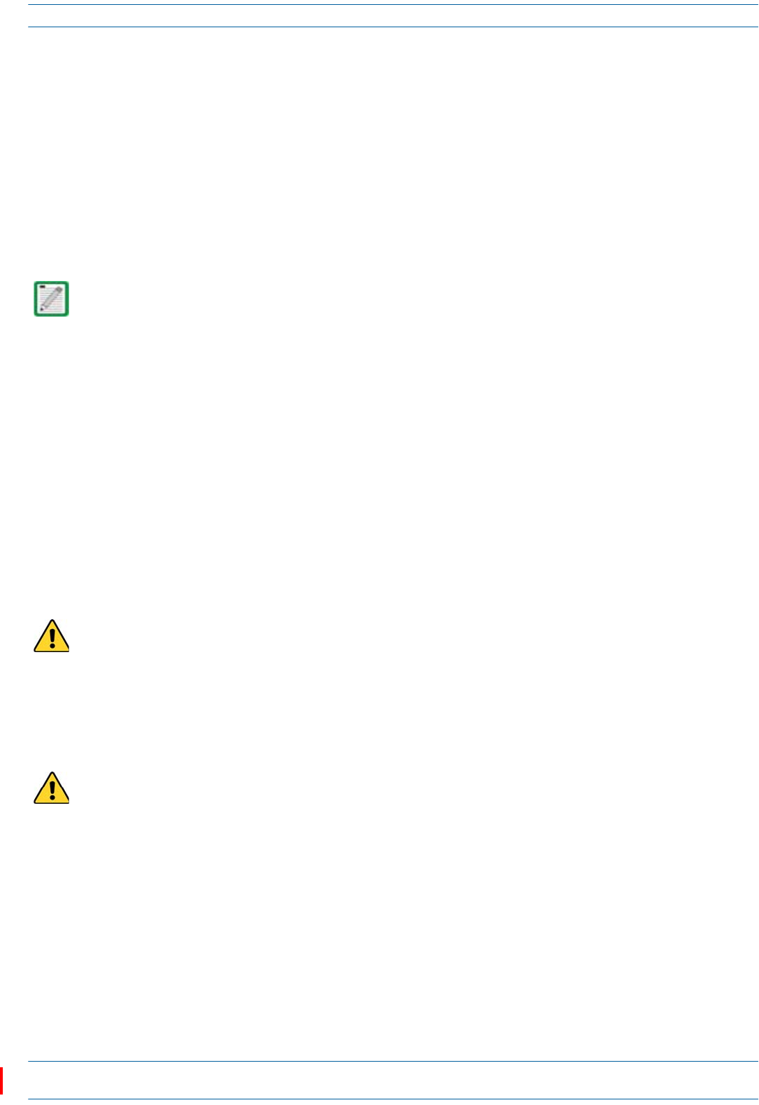
backtotheCAN/TEN.EachCAPLcanprovideRFcoverageforuptofourspecificfrequencybands.Figure2
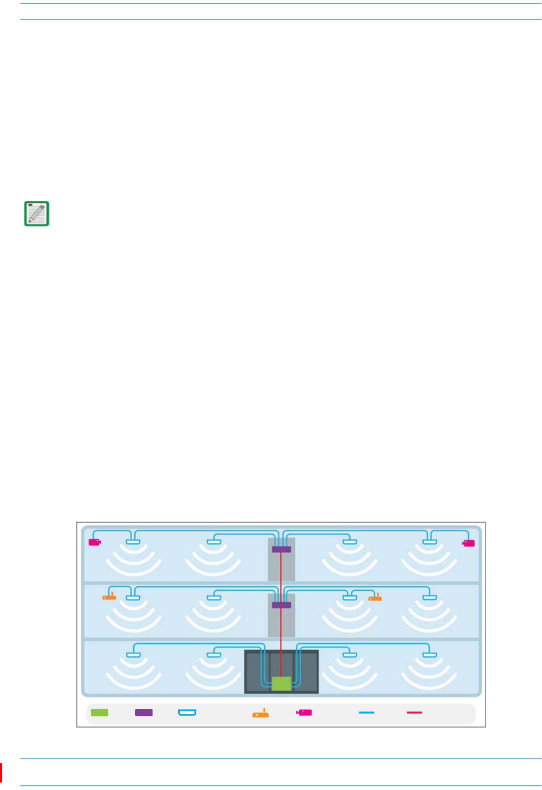
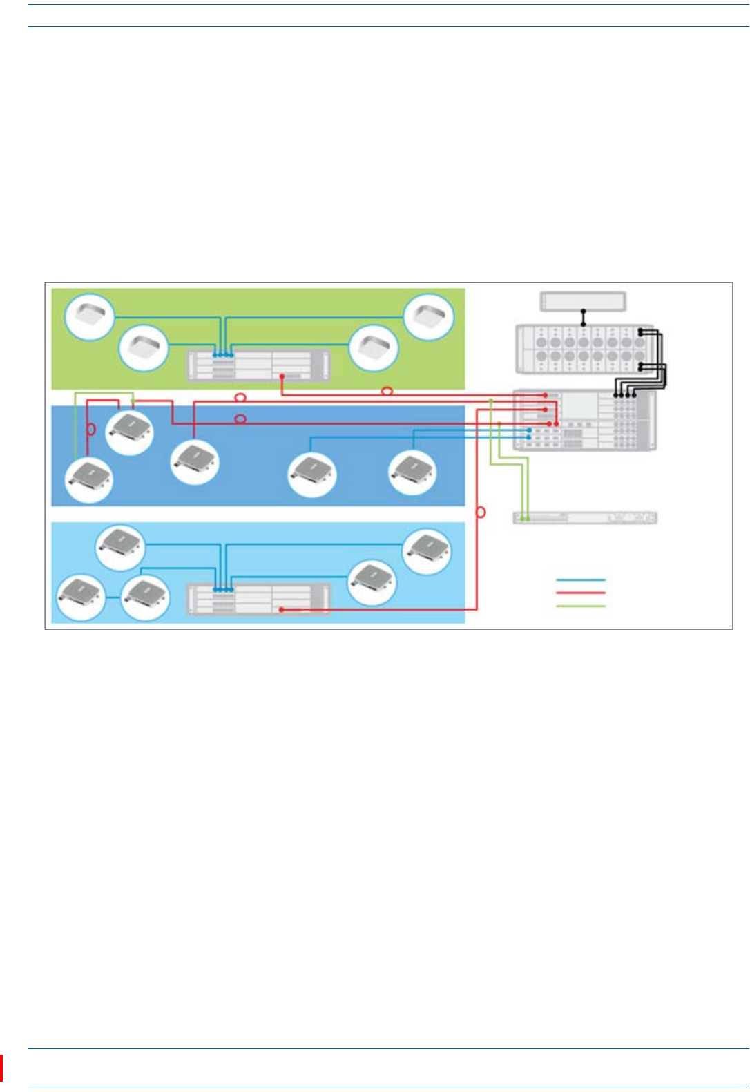
showshowaCAPLcanbedeployedinanION-Esystem.
Figure 2. CAP L in an ION-E System
TheCAPL
•operateswithinthefollowingtemperatureranges
–CAPLwithoutaFanKit(passivelycooled)
Opticalunits:-33°Cto+40°C(-27.4°Fto104°F)
Cat6Aunits:0°Cto+40°C(32°Fto104°F)
–CAPLwithaFanKit,themaximumoperatingtemperatureincreasesto55°C(131°F);seealso"Fan
Kit”onpage10
•isoutdoorrated(IP67),however,theCat6Aunitsarenotdesignedforoutdooruse;see"Determinethe
CAPLMountingSite”onpage19
•hasatypicalpowerconsumptionof98W;seealso
–"FanKit”onpage10
–"DeterminethePowerConsumptionoftheCAPL”onpage18.
UAP
UAP UAP
UAP
CAP L
CAP L
CAP L
CAP L CAP L
CAP L
CAP L
CAP L
CAP L
CAP L
Cat6A cable
Fiber
Power
TEN
TEN
Node B
e-POI
CAN
Remote
Powering

M0201AAC ION®-E Series Low Power Carrier Access Point Installation Guide
© February 2018 CommScope, Inc. Page 5
CAP L Overview
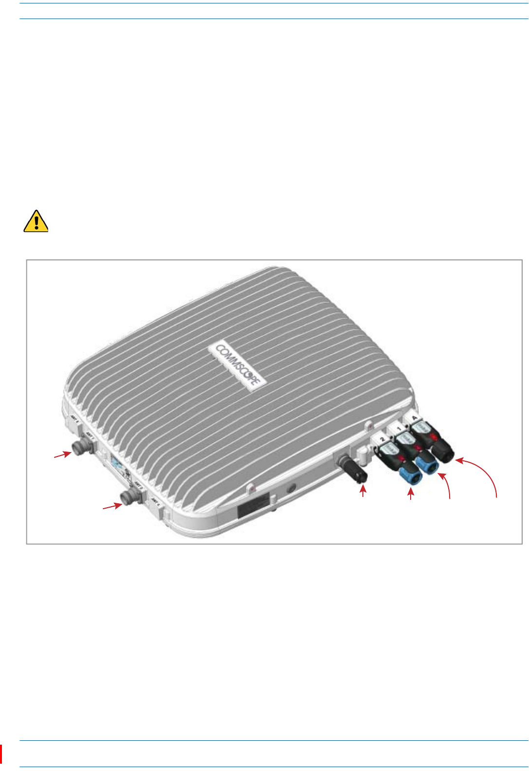
CAP L Connectors, Ports, and LEDs
Thefollowingsectionsidentifytheconnectors,ports,andLEDsavailableonthedifferentCAPLmodels.
•"CAPLwithanOpticalFiberInterface”onpage6
•"CAPLwithaCopperInterfaceandExternalDCPower”onpage7
•"CAPLwithaCopperInterfaceandPowerCat6ACable”onpage8
•"PoweringaCAPL”onpage48
•"FanInterfacePort”onpage9.
ION®-E Series Low Power Carrier Access Point Installation Guide M0201AAC
Page 6 © February 2018 CommScope, Inc.
CAP L Overview
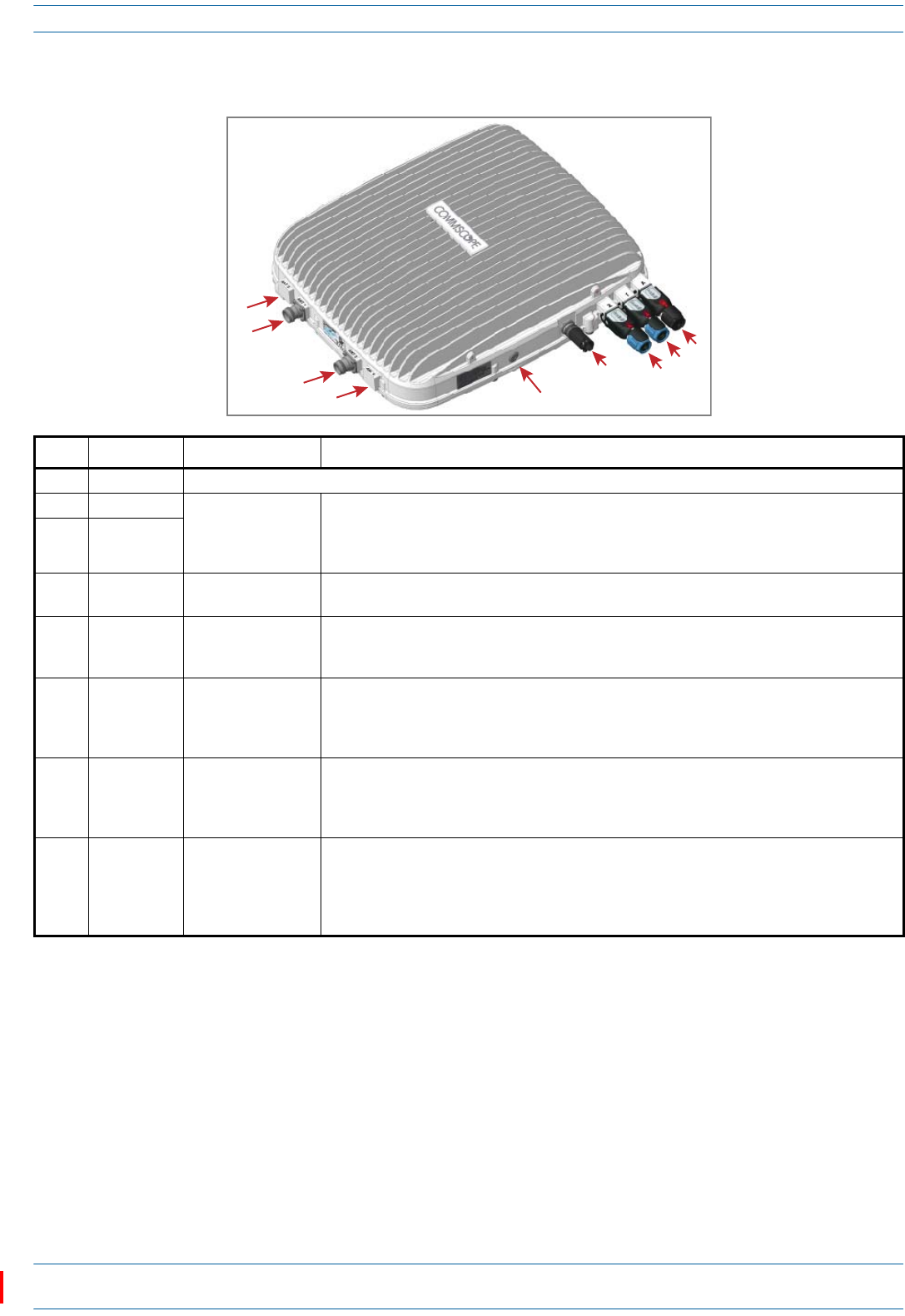
CAP L with an Optical Fiber Interface
REF # Label Description Function
1, 4 ANT 3, ANT 4 Not available; connector is plugged.
2 ANT 1 4.3-10 RF connector Connect to two separate external antennas or to two ports on a cross-polarized dual antenna
via 50Ω coaxial cable. Each connector supports two RF bands. The end of the 50Ω coaxial cable
that connects to an ANT connector can be either a push-pull or a threaded connector. ANT 1/2
ship with dust caps that can be discarded upon unit installation.
3ANT 2
5Power LED
(Unlabeled)
Power LED See "Power LED Behavior” on page 48.
6 Unlabeled Proprietary 4-pin 36
to 60 Vdc Power
connector
Connects to a local or remote DC power supply, or to a Hybrid Fiber Junction Box.
7 2 Optical Port 2 Connects to an optional cascaded CAP L via an Optical OCTIS Kit (PN 7770612). Port 2 provides
the main signal interface. Optical transport occurs over Single Mode Fiber (SMF) or Multi Mode
Fiber (MMF). Port 2 ships with factory-installed EMI/weatherproof plug, and must remain
plugged if not in use. Graphic shows the OCTIS connector in blue.
8 1 Optical Port 1 Connects to an ION-E CAN/TEN (possibly through a local Hybrid Fiber Junction Box) and
provides the main signal interface. Optical transport occurs over Single Mode Fiber (SMF) or
Multi Mode Fiber (MMF). Uses the Optical OCTIS Kit (PN 7770612). Port 1 ships with a dust cap
that can be discarded upon unit installation. Graphic shows the OCTIS connector in blue.
9 A RJ45 Auxiliary port Connects to external Ethernet devices such as WiFi and IP cameras. Cabling is via the
appropriate CAT cable for the protocol; this model supports a 1000 BASE-T and 802.3at Class 4
Power over Cat6A Ethernet connection. Maximum attached cable length is 3 meters (9.8 feet).
For information on the Auxiliary port in cascades, see "Cascade Rules” on page 17. Port A ships
with factory-installed EMI/weatherproof plug, and must remain plugged if not in use.
1
2
3
4
7
8
9
6
5
M0201AAC ION®-E Series Low Power Carrier Access Point Installation Guide
© February 2018 CommScope, Inc. Page 7
CAP L Overview
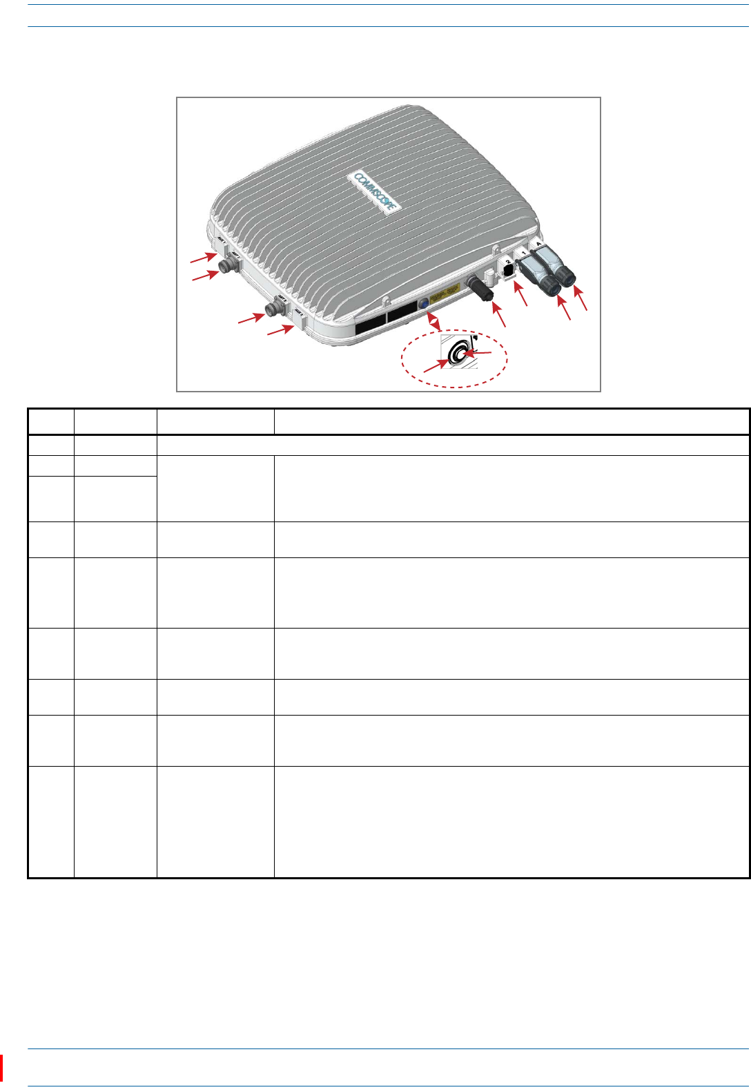
CAP L with a Copper Interface and External DC Power
REF # Label Description Function
1, 4 ANT 3, ANT 4 Not available; connector is plugged.
2ANT 1
4.3-10 RF connector
Connect to two separate external antennas or to two ports on a cross-polarized dual antenna
via 50Ω coaxial cable. Each connector supports two RF bands. The end of the 50Ω coaxial
cable that connects to an ANT connector can be either a push-pull or a threaded connector.
ANT 1/2 ship with dust caps that can be discarded upon unit installation.
3ANT 2
5Power LED
(Unlabeled)
Power LED See "Power LED Behavior” on page 48.
6 Power button
(Unlabeled)
Pushbutton switch Places the CAP L into a low-power sleep state, which allows you to safely unplug the CAP L
without a power arc.
Prior to disconnecting the Power cable from the CAP L, press the Power button to power off
the CAP L.
7 Unlabeled Proprietary 4-pin 36
to 60 Vdc Power
connector
Connects to a local or remote DC power supply, or to a Hybrid Fiber Junction Box.
8 2 Port 2 Not applicable to this model configuration—do not remove the factory-installed
EMI/weatherproof plug.
9 1 Port 1 Port 1 connects to an available port on a CAT Card in the CAN/TEN via Cat6A cable and
provides the main signal interface. Uses the Ethernet OCTIS Kit (PN 7760652). Port 1 ships with
a dust cap that can be discarded upon unit installation.
10 A RJ45 Auxiliary port The Auxiliary port provides a cascade connection to an optional locally powered cascaded
CAP L, or provides a connection to external Ethernet devices such as WiFi and IP cameras.
Cabling is via the appropriate CAT cable for the protocol; this model supports a 1000 BASE-T
and 802.3at Class 4 Power over Cat6A Ethernet connection. Maximum attached cable length
is 100 meters (328 feet). Port A ships with factory-installed EMI/weatherproof plug, and must
remain plugged if not in use. For information on how to use the Auxiliary port in cascades, see
"Cascade Rules” on page 17.
1
2
3
4
7
8
910
5
6
ION®-E Series Low Power Carrier Access Point Installation Guide M0201AAC
Page 8 © February 2018 CommScope, Inc.
CAP L Overview
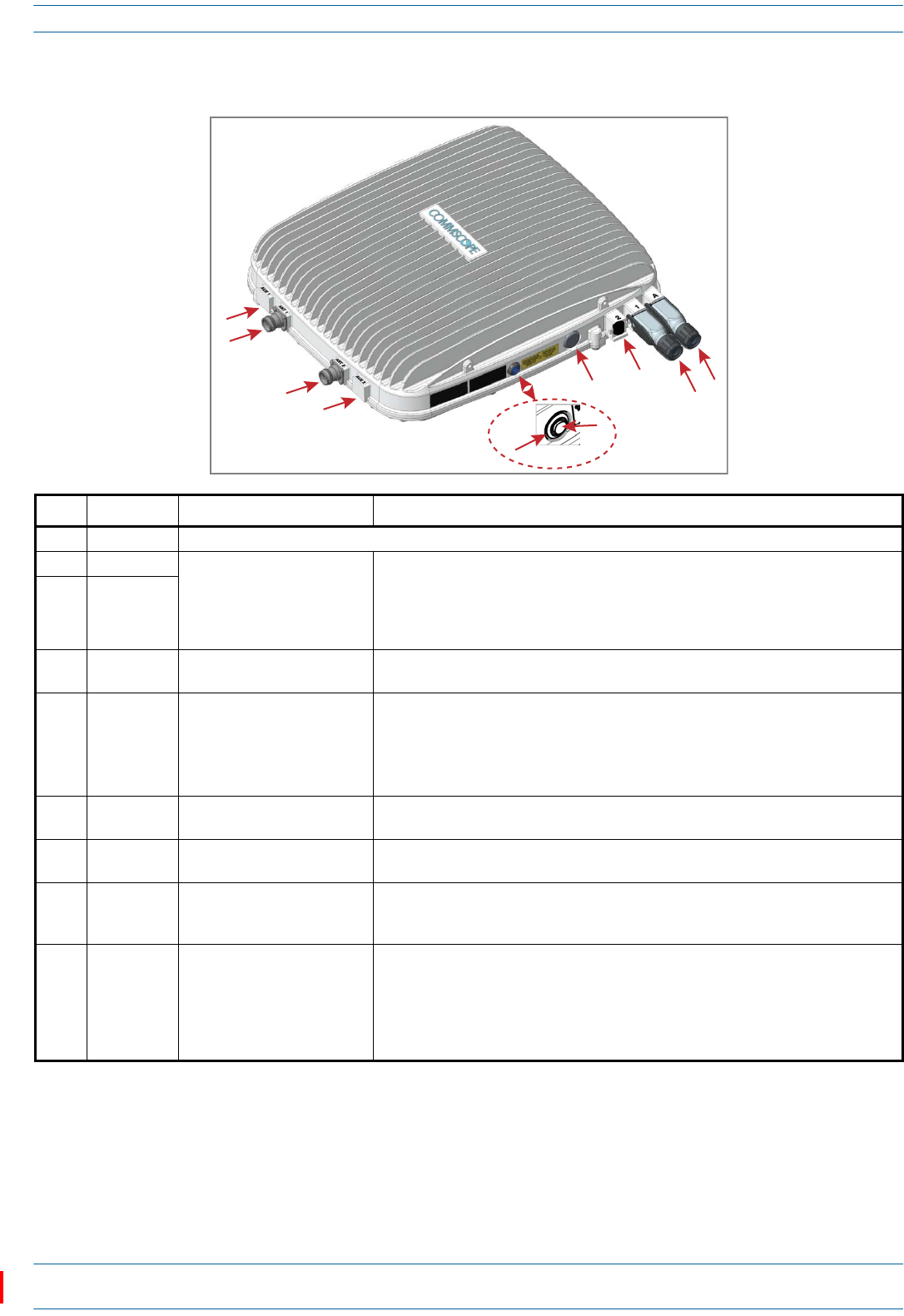
CAP L with a Copper Interface and Power Cat6A Cable
REF # Label Description Function
1, 4 ANT 3, ANT 4 Not available; connector is plugged.
2ANT 1
4.3-10 RF connector
Connect to two separate external antennas or to two ports on a cross-polarized dual
antenna via 50Ω coaxial cable. Each connector supports two RF bands. The end of the
50Ω coaxial cable that connects to an ANT connector can be either a push-pull or a
threaded connector. ANT 1/2 ship with dust caps that can be discarded upon unit
installation.
3ANT 2
5Power LED
(Unlabeled)
Power LED See "Power LED Behavior” on page 48.
6Power
button
(Unlabeled)
Pushbutton switch Places the CAP L into a low-power sleep state, which allows you to safely unplug the
CAP L without a power arc. PowertoaCat6A CAP L mayalsobeshutdownviathe
ION-ESeriesSoftware.
Prior to disconnecting the Power cable from the CAP L, press the Power button to
power off the CAP L.
7 Unlabeled Proprietary 4-pin 36 to 60 Vdc
Power connector Plugged, not applicable to this model configuration.
8 2 Port 2 Not applicable to this model configuration—do not remove the factory-installed
EMI/weatherproof plug.
9 1 Port 1 Port 1 connects to an available port on a CAT Card in the CAN/TEN via Cat6A cable and
provides the main signal interface and power over Cat6A. Uses the Ethernet OCTIS Kit
(PN 7760652). Port 1 ships with a dust cap that can be discarded upon unit installation.
10 A RJ45 Auxiliary port The Auxiliary port provides a cascade connection to an optional locally powered
Secondary CAP L, or provides a connection to external Ethernet devices such as WiFi
and IP cameras. Cabling is via the appropriate CAT cable for the protocol; this model
supports a 1000 BASE-T and 802.3at Class 4 Power over Cat6A Ethernet connection.
Maximum attached cable length is 100 meters (328 feet). Port A ships with
factory-installed EMI/weatherproof plug, and must remain plugged if not in use.
1
2
3
4
78
910
5
6
M0201AAC ION®-E Series Low Power Carrier Access Point Installation Guide
© February 2018 CommScope, Inc. Page 9
CAP L Overview
Fan Interface Port
Theprecedinggraphicshowstheproprietary8-pinFanInterfaceport,whichisonlyavailableonCAPLunits
thatshipwiththefactory-installedFanKit.IftheCAPLbeinginstalledincludestheFanKitoption,theFan
InterfaceportwillbecabledtotheFanKitatthefactory.IftheCAPLbeinginstalleddoesnotincludetheFan
Kitoption,theFanInterfaceportwillbeplugged.
CAP L Accessory Options
ThefollowingsectionsdescribehardwareoptionsfortheCAPL:
•"FanKit”onpage10
•"FlatMountingBracketKit”onpage10
•"CAPLMountingBracketKit”onpage10
•"CAPLHybridFiberSpliceBoxKit”onpage11
•"AC/DCPowerSupplyKit”onpage11
•"OCTISKits”onpage11.
Fan
Interface
port
ION®-E Series Low Power Carrier Access Point Installation Guide M0201AAC
Page 10 © February 2018 CommScope, Inc.
CAP L Overview
Fan Kit
TheoptionalFanKitisanintegratedshroudthatfitsovertheCAPLenclosuretoextendtheupperambient
temperaturerange.TheFanKit
•isIP55rated
•increasesthemaximumoperatingtemperatureto55°C(131°F)
•adds3WpowerconsumptiontotheCAPL;see"DeterminethePowerConsumptionoftheCAPL”on
page18.
•isfactoryinstalled,butcanbereplacedinthefield.
Flat Mounting Bracket Kit
TheFlatMountingBracketKit(CommScopePN7774353-xx)providesthemountingbracketsrequiredto
mountanCAPLtoawallorotherflatsurface.See"WallMountaCAPLUsingaFlatMountingBracketKit”on
page26.
CAP L Mounting Bracket Kit
TheCAPLMountingBracketKit(CommScopePN7774354-xx)providesthemountingbracketsrequiredto
mountanCAPLtoawallorotherflatsurfacewhenusingthe“CAPLHybridFiberSpliceBoxKit”orthe
“AC/DCPowerSupplyKit.”
Fan Kit
M0201AAC ION®-E Series Low Power Carrier Access Point Installation Guide
© February 2018 CommScope, Inc. Page 11
CAP L Overview
CAP L Hybrid Fiber Splice Box Kit
TheCAPLHybridFiberSpliceBoxKit(CommScopePN7781091-xx)separatesthepowerfromthefiber
signalsonahybridfiberfeedfromtheCAN/TEN.ItfeedspowertotheCAPLthroughacompositecablethat
includesbothfiberandcopperpowerwires.FiberandcopperterminateattheSpliceBox,whichallowsyou
toseparatetheDCwiresandfiberattheremoteend.ForCAPLswithaFiberInterface,youwilltypicallyuse
compositecabletotransportsignalandpower,andthenusetheCAPLHybridFiberSpliceBoxKitto
terminatethefiberattheCAPL.See"WallMountaCAPLUsingaCAPLHybridFiberSpliceBoxKit”on
page28.
AC/DC Power Supply Kit
TheAC/DCPowerSupplyKit(CommScopePN7775087-xx)providesa48VExternalPowerSupplythat
convertslocalACpowertoDCpowerfortheCAPL.WherevercopperisalreadyavailableforaCAPL
installation,aCAPLwithCopperInterfaceshouldbeinstalled.However,inacascade,PoEisonlyavailable
forthePrimaryCAPL—theSecondaryCAPLwillrequirelocalpowerandtheuseoftheAC/DCPowerSupply
Kit.Moreover,theAC/DCPowerSupplyKitcanbeusedforaFiberorCopperInterfacewhenremote
poweringisnotfeasible.See"WallMountaCAPLUsingaAC/DCPowerSupplyKit”onpage32.
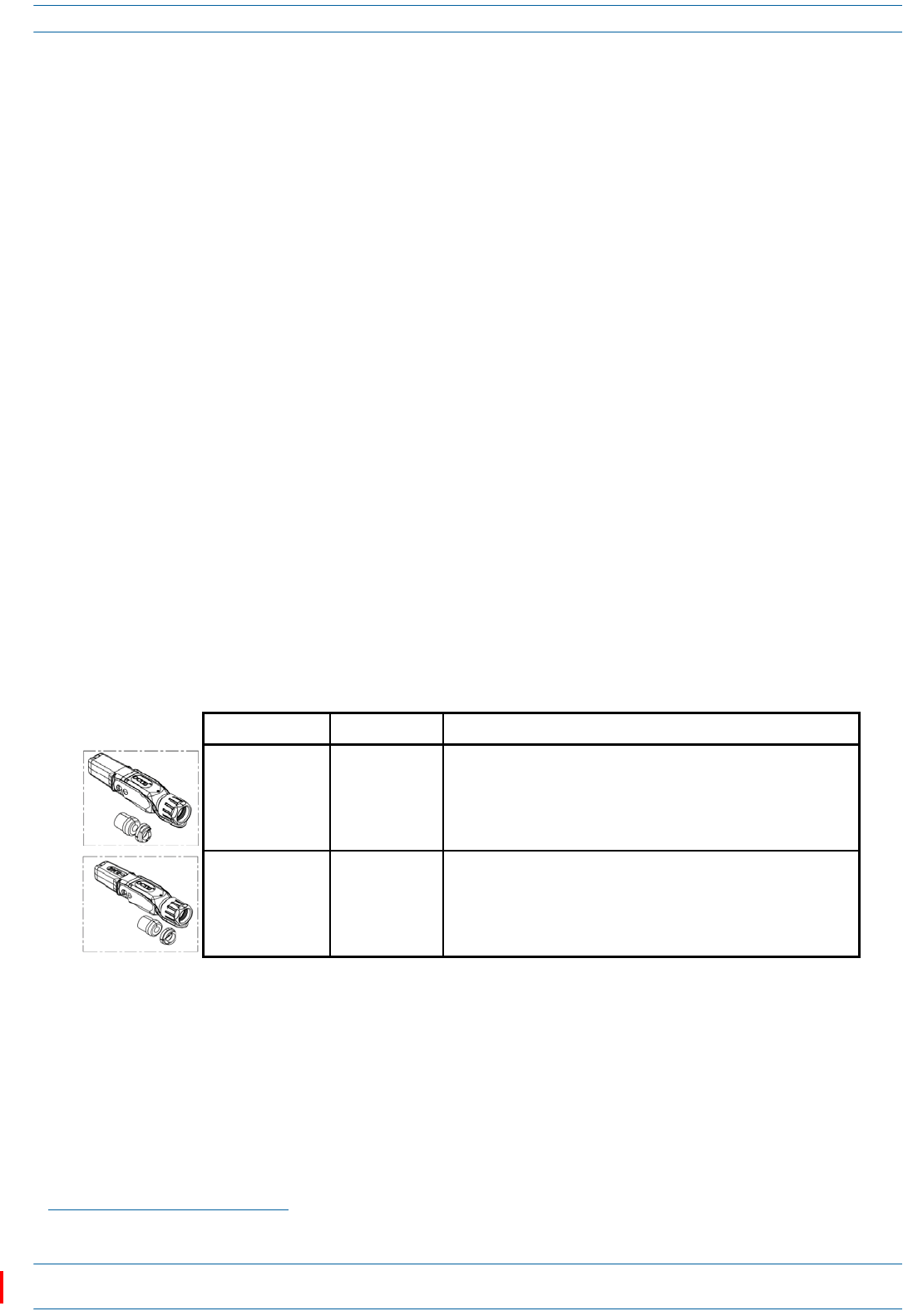
OCTIS Kits
AllCAPLsincludeoneOCTIS1KitfortheprimaryinterfacetotheCAN/TEN.RegardlessofwhichOCTISKit
shipswiththeCAPL,itwillplugintotheCAPLPort1.ItistheconfigurationoftheOCTISKitthatthenmakes
theAUXportcompatibleforaCopperInterfaceoraFiberInterface.
YoucanorderanadditionalOCTISKit,whichwouldallowyoutocascadetwoCAPLs,ortoattachanauxiliary
Ethernetdevice;whichOCTISKityoushouldorderisidentifiedinTable2.
1 OCTISisatrademarkofRADIALL.
Table 2. CAP LOCTIS Kits
Kit Name CommScope PN Description
Optical OCTIS Kit 7770612 Use only with CAP Ls with a Fiber Interface to cascade a Secondary
fiber unit.
Ethernet OCTIS Kit 7760652 Use with CAP Ls that have a Fiber or Copper Interface to cascade a
Secondary copper unit, or to attach an auxiliary Ethernet device.
ION®-E Series Low Power Carrier Access Point Installation Guide M0201AAC
Page 12 © February 2018 CommScope, Inc.
Safely Working with ION-E Hardware
SAFELY WORKING WITH ION-E HARDWARE
Thefollowingsectionsprovideimportantinformationthatyoushouldreadandknowbeforeworkingwith
anyION-Ehardware.Observeallcautionsandwarningslistedinthissection.
Health and Safety Precautions
.
Property Damage Warnings
General Installation Safety Requirements
A high leakage current ground (earth) connection to the Power Supply Unit (PSU) is essential before
making any other connections to the PSU.
Laser radiation. Risk of eye injury in operation. Do not stare into the laser beam; do not view the laser
beam directly or with optical instruments.
High frequency radiation in operation. Risk of health hazards associated with radiation from the
antenna(s) connected to the unit. Implement prevention measures to avoid the possibility of close
proximity to the antenna(s) while in operation.
Keep operating instructions within easy reach and make them available to all users.
Only license holders for the respective frequency range are allowed to operate this unit.
Read and obey all the warning labels attached to the unit. Make sure that all warning labels are kept in a
legible condition. Replace any missing or damaged labels.
Make sure the unit's settings are correct for the intended use (refer to the manufacturer product
information) and regulatory requirements are met. Do not carry out any modifications or fit any spare
parts, which are not sold or recommended by the manufacturer.
Wet conditions increase the potential for receiving an electrical shock when installing or using electrically
powered equipment. To prevent electrical shock, never install or use electrical equipment in a wet
location or during a lightning storm.
This system is a RF Transmitter and continuously emits RF energy. Maintain a minimum 12-inch (30 cm)
clearance from the antenna while the system is operating. Whenever possible, shut down the RAN before
servicing the antenna.
Do not remove caps from any of the connectors until instructed to do so.
The CAP L is to be used only with CommScope (NEC Class 2) or Limited Power Source ION-E Subrack, or
equivalent.
M0201AAC ION®-E Series Low Power Carrier Access Point Installation Guide
© February 2018 CommScope, Inc. Page 13
Safely Working with ION-E Hardware
Guard Against Damage from Electro-Static Discharge
Compliance
1Notice:Forinstallations,whichhavetocomplywithFCCRFexposurerequirements,theantenna
selectionandinstallationmustbecompletedinawaytoensurecompliancewiththoseFCCrequirements.
DependingontheRFfrequency,ratedoutputpower,antennagain,andthelossbetweentherepeaterand
antenna,theminimumdistanceDtobemaintainedbetweentheantennalocationandhumanbeingsis
calculatedaccordingtothisformula:
where
•P(mW)istheradiatedpowerattheantenna,i.e.themax.ratedrepeateroutputpowerinadditionto
theantennagainminusthelossbetweentherepeaterandtheantenna.
•PD(mW/cm²)istheallowedPowerDensitylimitacc.to47CFR1.1310(B)forgeneralpopulation/
uncontrolledexposureswhichis
–f(MHz)/1500forfrequenciesfrom300MHzto1500MHz
–1forfrequenciesfrom1500MHzto100,000MHz
RFexposurecompliancemayneedtobeaddressedatthetimeoflicensing,asrequiredbytheresponsible
FCCBureau(s),includingantennaco-locationrequirementsof1.1307(b)(3).
2Notice:ForinstallationswhichhavetocomplywithEuropeanEN50385exposurecompliance
requirements,thefollowingPowerDensitylimits/guidelines(mW/cm²)accordingtoICNIRParevalid:
•0.2forfrequenciesfrom10MHzto400MHz
•F(MHz)/2000forfrequenciesfrom400MHzto2GHz
•1forfrequenciesfrom2GHzto300GHz
3Notice:Installationofthisequipmentisinfullresponsibilityoftheinstaller,whohasalsothe
responsibility,thatcablesandcouplersarecalculatedintothemaximumgainoftheantennas,sothatthis
value,whichisfiledintheFCCGrantandcanberequestedfromtheFCCdatabase,isnotexceeded.The
industrialboostersareshippedonlyasanakedboosterwithoutanyinstallationdevicesorantennasasit
needsforprofessionalinstallation.
4Notice:ForinstallationswhichhavetocomplywithFCC/ISEDrequirements:
English:
ThisdevicecomplieswithFCCPart15.Operationissubjecttothefollowingtwoconditions:(1)this
devicemaynotcauseinterference,and(2)thisdevicemustacceptanyinterference,including
interferencethatmaycauseundesiredoperationofthedevice.
ThisdevicecomplieswithHealthCanada'sSafetyCode.TheinstallerofthisdeviceshouldensurethatRF
radiationisnotemittedinexcessoftheHealthCanada'srequirement.Informationcanbeobtainedat
http://www.hc-sc.gc.ca/ewh-semt/pubs/radiation/radio_guide-lignes_direct-eng.php.
Electro-Static Discharge (ESD) can damage electronic components. To prevent ESD damage, always wear
an ESD wrist strap when working with ION-E hardware components. Not all ION-E hardware requires
grounding. For those ION-E hardware components for which grounding is required, connect the ground
wire on the ESD wrist strap to an earth ground source before touching the ION-E component. Wear the
wrist strap the entire time that you work with the ION-E hardware.
]/[
][
][
2
4cmmW
mW
cm PD
P
D∗∗
=
π

ION®-E Series Low Power Carrier Access Point Installation Guide M0201AAC
Page 14 © February 2018 CommScope, Inc.
Safely Working with ION-E Hardware
Changesormodificationsnotexpresslyapprovedbythepartyresponsibleforcompliancecouldvoidthe
user'sauthoritytooperatetheequipment.
AntennaStmtforISED:
Thisdevicehasbeendesignatedtooperatewiththeantennashavingamaximumgainof9dBi.Antennas
havingagaingreaterthan9dBiareprohibitedforusewiththisdevicewithoutconsentbyISED
regulators.Therequiredantennaimpedanceis50ohms.
Theantenna(s)usedforthistransmittermustbeinstalledtoprovideaseparationdistanceofatleast30
cmfromallpersonsandmustnotbeco-locatedoroperatinginconjunctionwithanyotherantennaor
transmitter.Usersandinstallersmustbeprovidedwithantennainstallationinstructionsandtransmitter
operatingconditionsforsatisfyingRFexposurecompliance.
French:
CetappareilestconformeàFCCPartie15.SonutilisationestsoumiseàLesdeuxconditionssuivantes:(1)
cetappareilnepeutpasprovoquerd'interférenceset(2)cetappareildoitaccepterTouteinterférence,y
comprislesinterférencesquipeuventcauserunmauvaisfonctionnementdudispositif.
CetappareilestconformeavecSantéCanadaCodedesécurité6.Leprogrammed'installationdecet
appareildoits'assurerquelesrayonnementsRFn'estpasémisau-delàdeI'exigencedeSantéCanada.Les
informationspeuventêtreobtenues:
http://www.hc-sc.gc.ca/ewh-semt/pubs/radiation/radio_guide-lignes_direct-eng.php
Leschangementsoumodificationsnonexpressémentapprouvésparlapartieresponsabledela
conformitépourraientannulerl'autoritédel'utilisateuràutilisercetéquipement.
AntenneStmtpourISDE:
Cedispositifaétédésignépourfonctionneraveclesantennesayantungainmaximalde9dBi.Antennes
ayantungainplusgrandque9dBisontinterditespouruneutilisationaveccetappareilsansle
consentementdesorganismesderéglementationd'ISDE.L'impédanced'antennerequiseest50ohms.
L'antenne(s)utilisépourcetémetteurdoitêtreinstallépourfournirunedistancedeséparationd'au
moins30cmdetouteslespersonnesetnedoitpasêtreco-localiséesouopérantenconjonctionavecune
autreantenneouémetteur.Lesutilisateursetlesinstallateursdoiventêtrefournisavecdesinstructions
d'installationdel'antenneetdesconditionsdefonctionnementdel'émetteurpoursatisfairela
conformitéauxexpositionsRF.
5Notice:TheunitcomplieswithOvervoltageCategoryII.Italsocomplieswiththesurgerequirement
accordingtoEN61000-4-5(fineprotection);however,installationofanadditionalmedium(vialocal
supplyconnection)and/orcoarseprotection(externalsurgeprotection)isrecommendeddependingon
theindividualapplicationinordertoavoiddamagecausedbyovercurrent.
ForCanadaandUS,componentsusedtoreducetheOvervoltageCategoryshallcomplywiththe
requirementsofIEC61643-series.Asanalternative,componentsusedtoreducetheOvervoltage
CategorymaycomplywithANSI/IEEEC62.11,CSACertificationNoticeNo.516,CSAC22.2No.1,orUL
1449.Suitabilityofthecomponentfortheapplicationshallbedeterminedfortheintendedinstallation.
6Notice:Correspondinglocalparticularitiesandregulationsmustbeobserved.Fornationaldeviations,
pleaserefertotherespectivedocumentsincludedinthemanualCDthatisdeliveredwiththeunit.
7Note:ForaClassBdigitaldeviceorperipheral:
ThisequipmenthasbeentestedandfoundtocomplywiththelimitsforaClassBdigitaldevice,pursuant
topart15oftheFCCRules.Theselimitsaredesignedtoprovidereasonableprotectionagainstharmful
interferenceinaresidentialinstallation.Thisequipmentgenerates,usesandcanradiateradiofrequency
energyand,ifnotinstalledandusedinaccordancewiththeinstructions,maycauseharmfulinterference
toradiocommunications.However,thereisnoguaranteethatinterferencewillnotoccurinaparticular
installation.Ifthisequipmentdoescauseharmfulinterferencetoradioortelevisionreception,whichcan
M0201AAC ION®-E Series Low Power Carrier Access Point Installation Guide
© February 2018 CommScope, Inc. Page 15
Safely Working with ION-E Hardware
bedeterminedbyturningtheequipmentoffandon,theuserisencouragedtotrytocorrectthe
interference.
8Notice:ForaClassAdigitaldeviceorperipheral.
ThisequipmenthasbeentestedandfoundtocomplywiththelimitsforaClassAdigitaldevice,pursuant
toPart15oftheFCCRules.Theselimitsaredesignedtoprovidereasonableprotectionagainstharmful
interferencewhentheequipmentisoperatedinacommercialenvironment.Thisequipmentgenerates,
uses,andcanradiateradiofrequencyenergyand,ifnotinstalledandusedinaccordancewiththe
instructionmanual,maycauseharmfulinterferencetoradiocommunications.Operationofthis
equipmentinaresidentialareaislikelytocauseharmfulinterferenceinwhichcasetheuserwillbe
requiredtocorrecttheinterferenceathisownexpense.
9Note:ThisunitcomplieswithEuropeanstandardEN60950-1/EN62368-1.
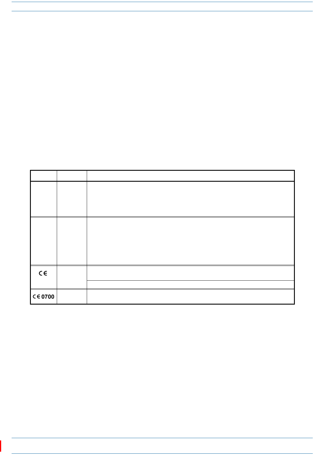
Equipment Symbols Used / Compliance
Pleaseobservethemeaningsofthefollowingsymbolsusedinourequipmentandthecompliancewarnings
listedinTable3.
Table 3. Compliance Labels
Symbol Compliance Meaning
—FCC
For industrial (Part 20) signal booster:
WARNING: This is NOT a CONSUMER device. It is designed for installation by FCC LICENSEES and
QUALIFIED INSTALLERS. You MUST have an FCC LICENSE or express consent of an FCC Licensee to
operate this device. Unauthorized use may result in significant forfeiture penalties, including
penalties in excess of $100,000 for each continuing violation.
—ISED
WARNING: This is NOT a CONSUMER device. It is designed for installation by an installer approved
by an ISED licensee. You MUST have an ISED LICENCE or the express consent of an ISED licensee to
operate this device.
AVERTISSEMENT: Ce produit N'EST PAS un appareil de CONSOMMATION. Il est conçu pour être
installé par un installateur approuvé par un titulaire de licence d'ISDE. Pour utiliser cet appareil,
vous DEVEZ détenir une LICENCE d'ISDE ou avoir obtenu le consentement exprès d'un titulaire de
licence autorisé par ISDE.
CE
To be sold exclusively to mobile operators or authorized installers - no harmonized frequency
bands, operation requires license. Intended use: EU and EFTA countries.
Indicates conformity with the RED directive 2014/53/EU and/or RoHS directive 2011/65/EU.
CE Indicates conformity with the RED directive 2014/53/EU and RoHS directive 2011/65/EU certified
by the notified body no. 0700.
ION®-E Series Low Power Carrier Access Point Installation Guide M0201AAC
Page 16 © February 2018 CommScope, Inc.
Installing CAP Ls
INSTALLING CAP LS
ThefollowingsectionsguideyouthroughtheinstallationofaCAPL.payattentiontoallcautions,andfollow
thestepsintheorderpresented.
Prepare for Installation
Dothefollowingbeforebeginninginstallation.
•Reviewandknowthecautionsin"SafelyWorkingwithION-EHardware”onpage12.
•Reviewthesystemdesignplan.
•Identifytheequipmentinstallationsite.
•Reviewthepowerrequirementstomakesurethesitecansupportthisinstallation.
•Mapoutallcableruns.
•Identifyandobtainalltoolsandmaterialsrequiredtocompletetheinstallation.
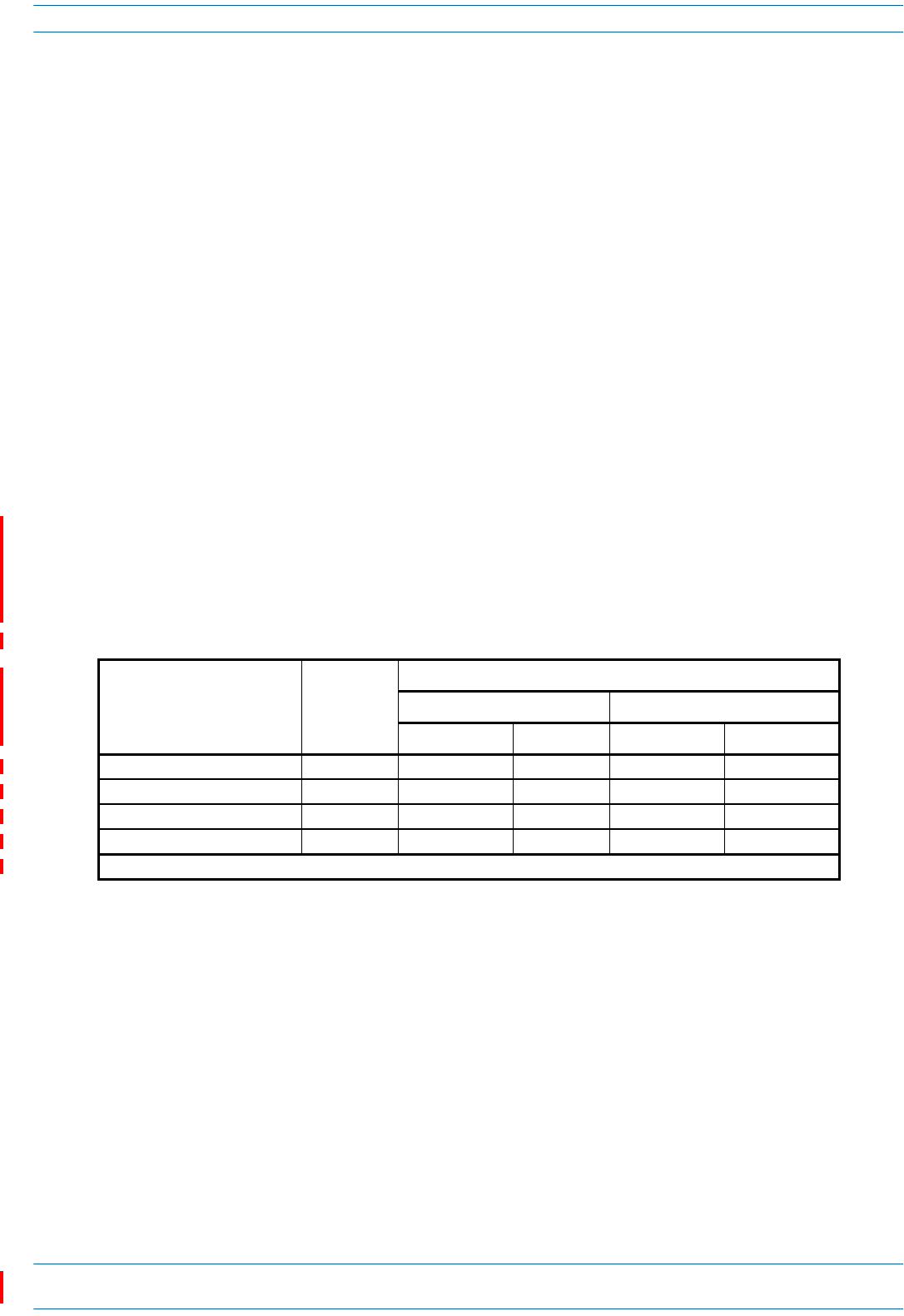
Required Distances Between CAP Ls and Antennas
Table4liststhedistancethatmustbemaintainedbetweenspecificCAPLmodelsandantennas.Seealsothe
requirementslistedin“AntennaStmtforISED:”and“AntenneStmtpourISDE:”onpage14.
CAP L Installation Rules
WheninstallingaCAPL,youmustobservethefollowingrules.
•CAPLwithCopperInterface
–ConnectsviaitsRJ-45porttoaCATCardintheCAN/TEN
–EachCATPortcansupporttwoCopperCAPLs,butyoucannotexceedsixCAPLsperCATCard,for
maximumtotalsof24CAPLsinastraightcascadeconfiguration,and32CAPLsperWCSSubrackin
adaisy-chainconfiguration,butyoumustadheretotheCopperCAPLpoweringrules.
–Therecanbeatotalof12CAPLsconnectedtoaCATCardinacascadeconfiguration.TheCAPL
connectedtotheCATCardisthePrimaryCAPL,towhichyoucanconnectoneself-powered
SecondaryCAPL.See"CascadeRules”onpage17.
Table 4. Required Antenna Distance
CAP L Model
Antenna gain
without cable
loss [dBi]
Maximum Distance
FCC ISED
Meters Inches Meters Inches
CAP L 7 /80-85/17 E / 19 9 .176 6.9 .256 10.1
CAP L 17E/17E/19/19 9 .218 8.58 .259 10.2
CAP L 1 7E/17E/2 3 / 2 3 9 .169 6.65 .237 9.33
CAP L 1 7E/19/2 3 / 2 5TDD 9 .178 1 7.02
1 .183 1 7.22 1
1 These values were determined by calculation rather than by measurement.

M0201AAC ION®-E Series Low Power Carrier Access Point Installation Guide
© February 2018 CommScope, Inc. Page 17
Installing CAP Ls
•CAPLwithFiberInterface
–ConnectsviaitsOpticalPort1toanOPTCardintheCAN/TEN
–Youcanconnectupto4CAPLsperOPTCardforatotalof16.
–YoucanconnectuptothreeCAPLunits(orcascadedpairs)toOPTCardPorts1-4.See"Cascade
Rules”onpage17.
Cascade Rules
WhencascadingaSecondaryCAPLoranexternalEthernetdevicesuchasWiFioranIPcamera,youmust
observethefollowingrules,whicharealsodocumentedintheinstallationproceduresincludedinthis
installationguide.
•Inacascade,theCAPLconnecteddirectlytotheCAN/TENisthePrimaryCAPL,andtheCAPLthat
connectstothePrimaryCAPListheSecondaryCAPL.
•Thecascadedunitmustusethesametransporttype(CopperorOptical).
–TocascadetwoOpticalCAPLs,useafiber-opticcable.
–TocascadetwoCopperCAPLs,useCat6Acable.Use23AWGCat6Acable;forcablelimitations,see
"Cat6ACableRequirementsforCAPLswithaCopperInterface”onpage40.
•TheSecondaryCAPLmustgetitspowerthroughtheDCconnector.ForCAPLswithaCopperInterface,
powerovertheCat6Acabletothecascadedunitisnotsupported.
•YouconnectCAPLswithaCopperInterfacetoaCATCardintheWCSSubrack.EachCATCardhasfour
RJ-45ports(labeled1-4).
–YoucanconnectuptothreeCAPLswithaCopperInterface(orcascadedpairs)toCATCardPorts
1-3.
–IfinstalledinCATCardPort4,theCAPLwithCopperInterfacemustbelocallypowered.
•YouconnectCAPLswithaFiberInterfacetoanOPTCardintheWCSSubrack.EachOPTCardhasfour
10Gbpsports(labeled1-4)forfiberconnections.
–Youcanconnectupto4CAPLsperOPTCardforatotalof16.
–Inacascade,theCAPLconnectedtotheOPTCardisthePrimaryCAPL,towhichyoucanconnectone
SecondaryCAPL.
•UseoftheAuxiliaryportsinacascadedsystemislimitedasdescribedbelow.
–ForCAPLswithaFiberInterface,onlyusetheAuxiliaryportonthePrimaryCAPL.
–ForCAPLswithaCopperInterface,usetheAuxiliaryportonthePrimaryCAPLtoconnectoneofthe
following:
alocallypoweredSecondaryCAPL
anexternalEthernetdevicesuchasWiFioranIPcamera.
•Thetotal320MHzRFbandwidthissharedbetweenthetwocascadedunits,butcanbesharedunevenly;
thatis,withmorebandwidthgoingtoeitherthePrimaryorSecondaryCAPL—eitherCAPLcantransmit
allthe320MHzRFbandwidthoranysubsetofit.
•AfterthePrimaryCAPLpowersup,theSecondaryCAPLwillbediscoveredandpoweruponitsown;for
informationonhowaCAPLpowersup,see"PoweringaCAPL”onpage48.
ION®-E Series Low Power Carrier Access Point Installation Guide M0201AAC
Page 18 © February 2018 CommScope, Inc.
Installing CAP Ls
Recommended Tools and Material
•ElectrostaticDischarge(ESD)wriststrap
•DrillandbitstomountCAPLtoawallorceiling
•Fibercleaningequipment
•ifrequiredperlocalpractice,insulatedstrandedcopperwireforchassisground;see"(Optional)Ground
theCAPL”onpage36.
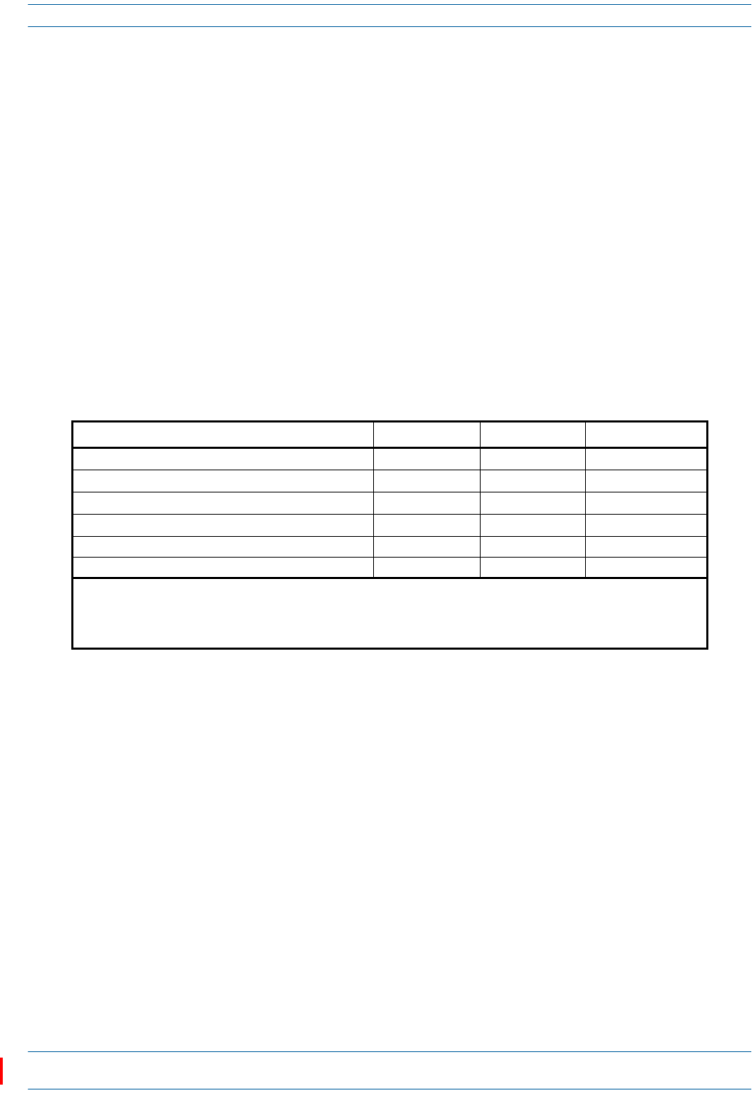
Determine the Power Consumption of the CAP L
UsethepowerconsumptionmatrixinTable5tocalculatepowerconsumptionforaCAPL,where
•theconsumptionnumbersareattheCAPLpowerinputsanddonotaccountforfeedlosses
•themaximumconsumptionnumbersinTable5donotincludethepowerconsumedbyanyattached
auxiliarydevices.BothCAPLpowerconsumptionandauxiliarydevicepowermustbeincludedwhen
calculatingfeedlosses.
Table 5. CAP L Power Consumption
Configuration Voltage Range (V) Typical Power (W) Maximum Power (W)
Optical Fiber Interface without Fan Kit 1, 2 36 - 60 92 102
Optical Fiber Interface with Fan Kit 1, 2 36 - 60 95 107
Copper Interface and External DC Power without Fan Kit 1 36 - 60 100 110
Copper Interface and External DC Power with Fan Kit 1 36 - 60 103 115
Copper Interface and Power Cat 6A Cable without Fan Kit <60V maximum 100 110
Copper Interface and Power Cat 6A Cable with Fan Kit <60V maximum 103 115
1 Does not include consumption of optional local DC supply.
2 Optical unit does not include SFP+ Module consumption. Can support up to 3W (more with engineering consultation)
maximum total SFP+ Module consumption. Typical installation (sufficient for SM up to 10km or MM) would be 0.8W
typical, 1.0W max for each SFP+ Module.
M0201AAC ION®-E Series Low Power Carrier Access Point Installation Guide
© February 2018 CommScope, Inc. Page 19
Installing CAP Ls
Determine the CAP L Mounting Site
Whendecidingonasuitablemountingsite,observethefollowingrules;referalsoto"MountingOrientation
forWallMounts”onpage24.
•TheCAPLissuitableforinstallationindoorsforanyunit.
•CommScoperecommendsthataCAPLwithanOpticalFiberInterfacebeinstalledoutdoorsonlyifithas
aFanKit.
•UsetheweightslistedinTable6todetermineasitethatcanbeartheweightoftheCAPLthatisbeing
installed,where:
–The“MaximumLiftWeight”isthehighestweightthatmustbeliftedduringinstallation.(Aninstaller
onlyneedstoliftCAPLcomponentsatonetime,notthewhollyconfiguredCAPL.)
–The“TotalHangingWeight”istheweightoftheCAPL,includingtheweightoftheMountingBracket
andPowerSupply,minustheweightoftheexternalcablesandconnectors,thatthemountingsite
mustbeabletosupport.
•UsethedimensionsshowninFigure3onpage20throughFigure5onpage21.
A CAP L with a Copper Interface is not designed for outdoor installations—it is not lightning protected.
However, the antenna to which the Copper Interface units attach can be outdoors if suitable
lightning-protection devices are used at the antenna site.
Table 6. Maximum CAP L Installation Weights*
CAP L configured with this kit …
Maximum Lift Weight Total Hanging Weight
No Fan Kit With Fan Kit No Fan Kit With Fan Kit
kg lbs. kg lbs. kg lbs. kg lbs.
Flat Mounting Bracket 10.8 23.8 11.3 25 10.8 23.8 11.3 25
AC/DC Power Supply Kit 10.7 23.6 11.2 24.7 13.2 29 13.7 30.2
CAP L Hybrid Fiber Splice Box Kit 10.7 23.6 11.2 24.7 12.2 26.9 12.7 28
ION®-E Series Low Power Carrier Access Point Installation Guide M0201AAC
Page 20 © February 2018 CommScope, Inc.
Installing CAP Ls
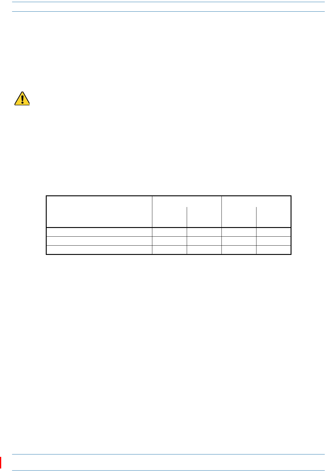
Figure 3. Mounting Dimensions for a CAP L with the Flat Mounting Bracket Kit
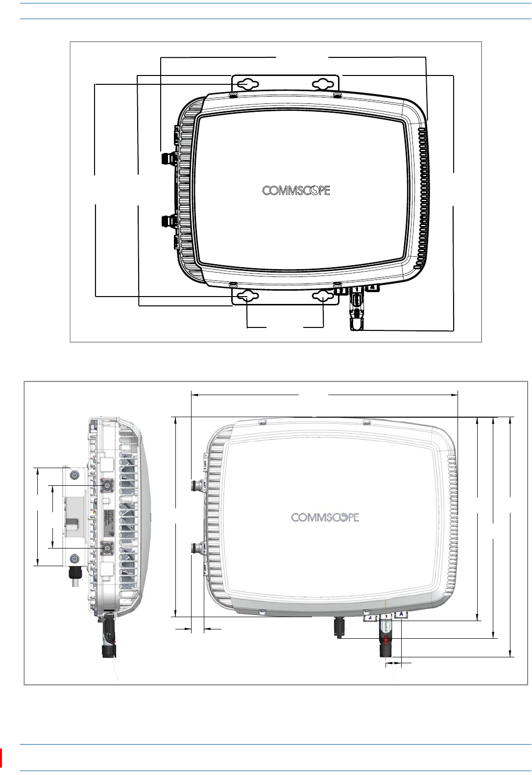
Figure 4. Mounting Dimensions for a CAP L Mounted with the CAP L Hybrid Fiber Splice Box Kit
489.12mm
[19.26”]
512mm
[20.16”]
144mm
[5.67”]
440mm
[17.32”]
406.4mm
[16”]
120mm
[4.72"]
383.34mm
[15.09"]
512mm
[20.16”]
30mm
2X
[1.18"]
424.53mm
[16.71"]
390.33mm
[15.37"]
24mm
[0.94"]
2X
188mm
[7.4"] 460.75mm
[18.14"]
M0201AAC ION®-E Series Low Power Carrier Access Point Installation Guide
© February 2018 CommScope, Inc. Page 21
Installing CAP Ls
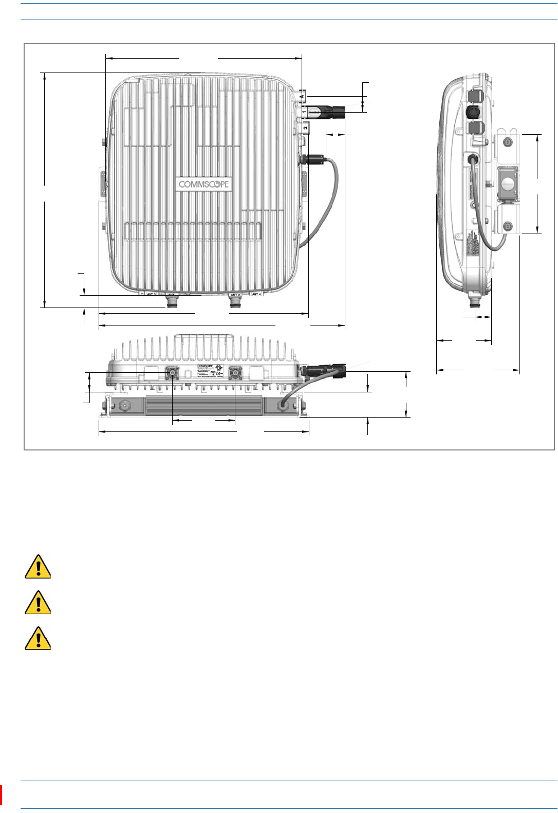
Figure 5. Mounting Dimensions for a CAP L Mounted with the AC/DC Power Supply Kit
General Mounting Cautions
ThefollowingcautionsapplytoallCAPLinstallations;theremaybeothermountingcautionsapplicabletoa
specificmountingoption,whichwillbedefinedintheapplicablemountingprocedure.
Attach all CAP Ls securely to a stationary object as described in this installation guide.
To maintain proper ventilation, keep at least 76 mm (3-inch) clearance around the CAP L.
The installation site must be able to bear the weight of the CAP L; see Table 6 on page 19.
120mm
[4.724"]
36.5mm
[1.437"]
48.69mm
[1.917"]
447.979mm
[17.637"]
24.106mm
[0.949"]
373.873mm
[14.719"]
87.44mm
[3.443"]
399.8mm
[15.74"] 469.62
[18.489"]
35.727mm
[1.407"]
30mm
[1.181"]
2X
401mm
[15.787"]
158.42mm
[6.237"]
188mm
[7.402"]
104.73mm
[4.123"]
31.5mm
[1.24"]

ION®-E Series Low Power Carrier Access Point Installation Guide M0201AAC
Page 22 © February 2018 CommScope, Inc.
Installing CAP Ls
Unpack and Inspect the CAP L and Optional Accessories
1Inspecttheexterioroftheshippingcontainer(s)forevidenceofroughhandlingthatmayhavedamaged
thecomponentsinthecontainer.
2Unpackeachcontainerwhilecarefullycheckingthecontentsfordamageandverifywiththepackingslip.
3Ifdamageisfoundorpartsaremissing,fileaclaimwiththecommercialcarrierandnotifyCommScope
TechnicalSupport(see"DCCSGlobalTechnicalSupport”onpage51).Savethedamagedcartonsfor
inspectionbythecarrier.
4Saveallshippingcontainersforuseiftheequipmentrequiresshipmentatafuturedate.
Mount the CAP L
TheCAPLissuitableforindoorandoutdoorinstallationsasfollows:
•Indoors—AllversionsoftheCAPLcanbeinstalledindoors.
•Outdoors—
–OnlyOpticalFiberCAPLswiththeoptionalFanKitcanbeinstalledoutdoors.
–DonotinstallCopperCAPLs(thatis,haveCat6Acabling)outdoorsastheyarenotdesignedfor
outdoortemperatures,nordotheyhaverequiredlightningprotection.
Mountinginstructionsaredividedintothesectionslistedbelow.
•Thefollowingsectionsapplytoallinstallations.
–"GeneralMountingCautions”onpage21
–"MountingOrientationforWallMounts”onpage24.
•Followthemountinginstructionsthatareappropriateforthisinstallation:
–"Flat-SurfaceMountaCAPL”onpage23
–"WallMountaCAPLUsingaFlatMountingBracketKit”onpage26
–"CeilingMountaCAPLwithaFanKit”onpage35
–"WallMountaCAPLUsingaAC/DCPowerSupplyKit”onpage32.

M0201AAC ION®-E Series Low Power Carrier Access Point Installation Guide
© February 2018 CommScope, Inc. Page 23
Installing CAP Ls
Flat-Surface Mount a CAP L
YoucanplaceaCAPLonaflatsurface,suchasashelf,desk,cabinet,aboveaceiling,oranyotherhorizontal
surfacethatallowsstableplacement.
IfyoumounttheCAPLonaflatsurface,inadditiontotheruleslistedin"GeneralMountingCautions”on
page21,youmustalsoobservethefollowingrulesthatarespecifictoaflat-surfacemount.
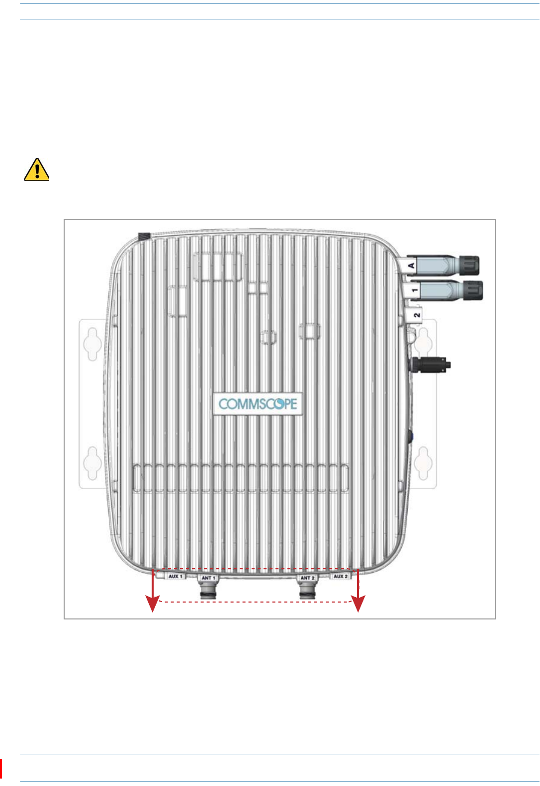
Figure 6. CAP L Orientation in Flat-Surface Mounting
AfteryoumounttheCAPLonaflatsurface,followthestepsin"ConnecttheCAPLCables”onpage37.
To maintain proper ventilation, keep at least 76 mm (3-inch) clearance around the CAP L.
Do not stack CAP Ls on top of each other.
Always secure the CAP L to the mounting surface.
If a CAP L without a Fan Kit is flat-surface mounted, the minimum clearance above the CAP L is 203.2
millimeters (8 inches).
Always mount the CAP L with its mounting option facing down against the mounting surface, and the
enclosure fins facing up; see Figure 6.
If you are mounting the CAP L above a ceiling, its antennas must protrude below the ceiling. That is, the
CAP L will be above the ceiling, but any connected WiFi units or IP cameras will be mounted below the
ceiling; see Figure 6.
Fins facing up
Flat Suface
Flat-Mounng Bracket
opon is securing the
CAP L to the flat
surface.
Fins Facing down
If the CAP L does not have a Fan Kit, do not Flat-Suface Mount with the CAP L Fins facing down.
ION®-E Series Low Power Carrier Access Point Installation Guide M0201AAC
Page 24 © February 2018 CommScope, Inc.
Installing CAP Ls
Wall Mount a CAP L
ThefollowingsectionsprovidetheinstallationmethodologyandstepsrequiredtomountaCAPLtoawall.
Mounting Orientation for Wall Mounts
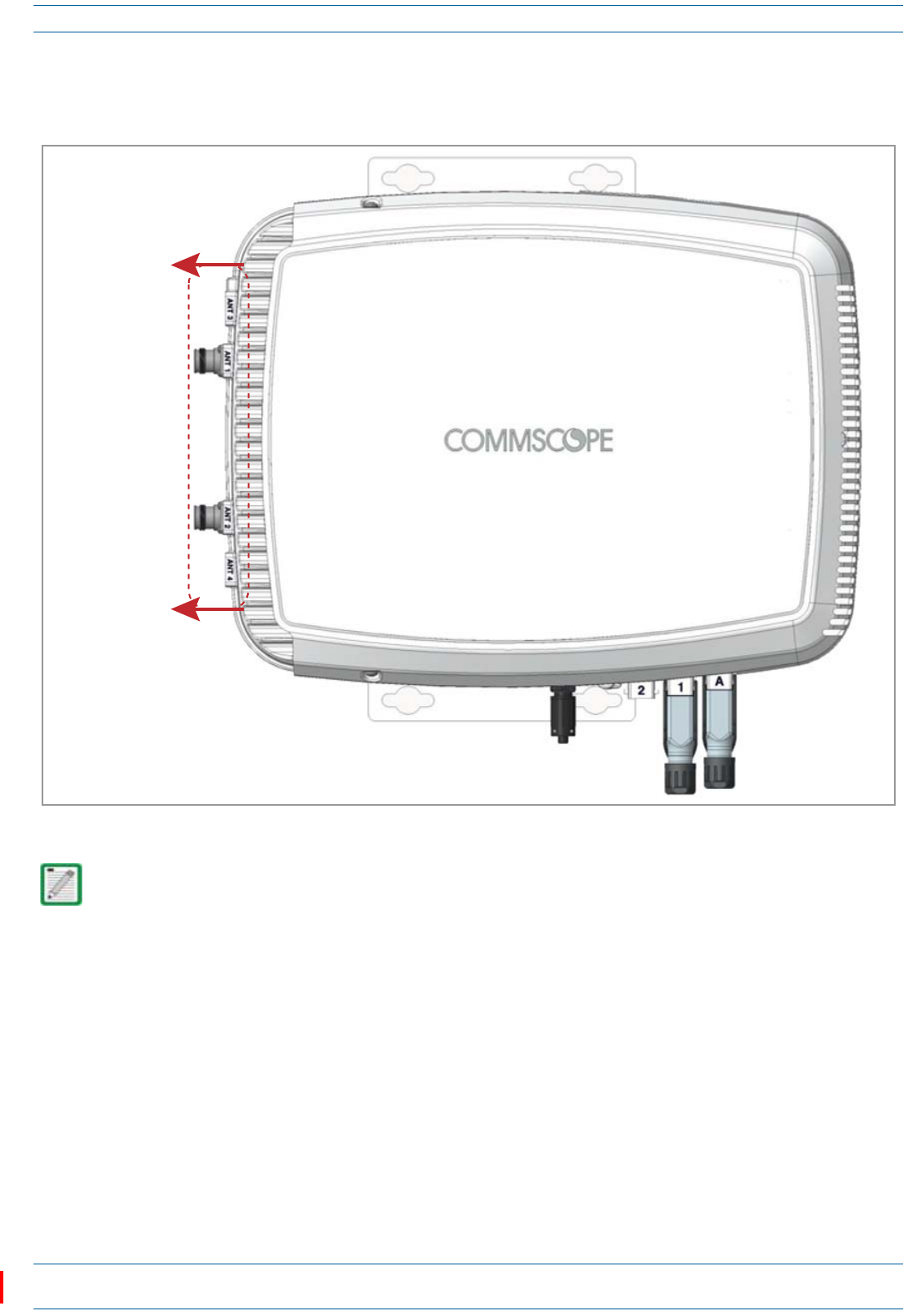
WhenwallmountingaCAPL,therecommendationsshouldbeobserved.
•WallMountOrientationforaCAPLwithoutaFanKit
Figure 7. Mounting Orientation for a CAP L without the Optional Fan Kit (Flat Mounting Bracket Shown)
A CAP L that does not have a Fan Kit is passively cooled. You should therefore mount a CAP L that does not
have a Fan Kit with the ANT ports pointing down (see Figure 7). Otherwise, the CAP L will have a reduced
maximum operating temperature of 33°C (91°F).
ANT connectors poinng down
M0201AAC ION®-E Series Low Power Carrier Access Point Installation Guide
© February 2018 CommScope, Inc. Page 25
Installing CAP Ls
•WallMountOrientationforaCAPLwithaFanKit—ToallowforoptimalaccesstotheCAPLcables,it
isrecommendedthataCAPLwiththeFanKitoptionbemountedwiththeANTportsarepointingtothe
left;seeFigure8.
Figure 8. Mounting Orientation for a CAP L with the Optional Fan Kit (Flat Mounting Bracket Shown)
Mounting requirements for flat surfaces are described in "Flat-Surface Mount a CAP L” on page 23.
Ceiling-mount requirements are described in "Ceiling Mount a CAP L with a Fan Kit” on page 35.
ANT connectors
poinng to the le
ION®-E Series Low Power Carrier Access Point Installation Guide M0201AAC
Page 26 © February 2018 CommScope, Inc.
Installing CAP Ls
Wall Mount a CAP L Using a Flat Mounting Bracket Kit
1Followthestepsin"UnpackandInspecttheCAPLandOptionalAccessories”onpage22.
2Refertoandobserveallcautionslistedin"GeneralMountingCautions”onpage21.
3Referto"DeterminetheCAPLMountingSite”onpage19todeterminethemountinglocation,whichmust
beabletosupporttheweightanddimensionsoftheCAPL.
4Referto"MountingOrientationforWallMounts”onpage24todeterminethemountingorientationofthe
CAPL.
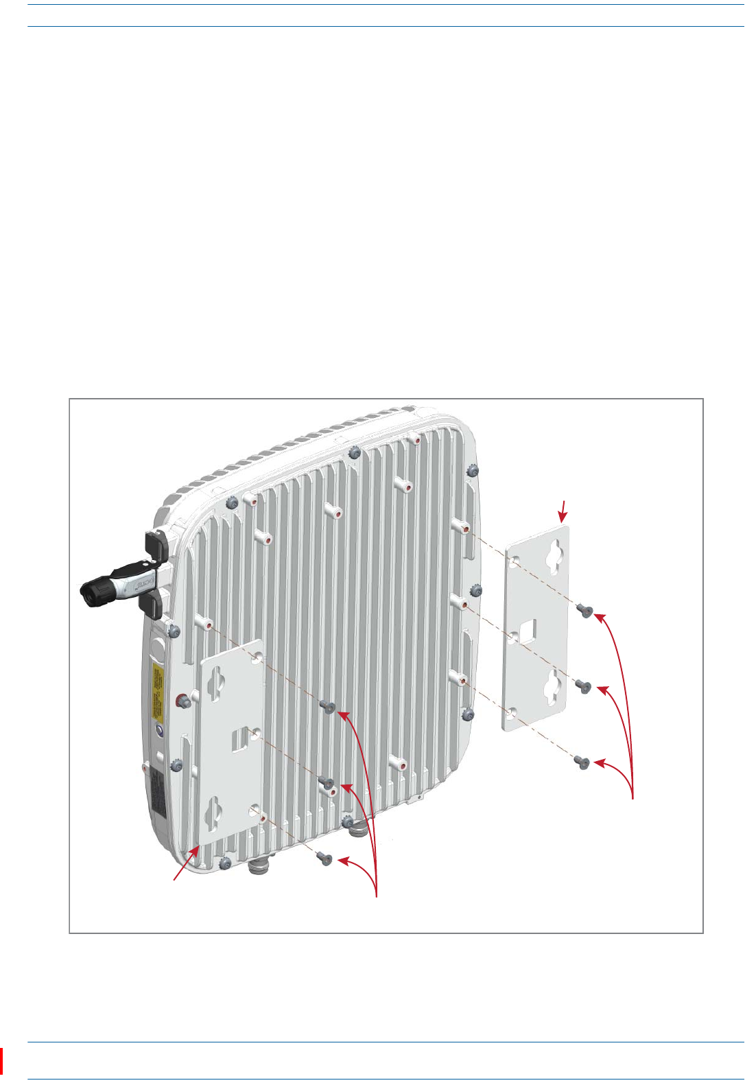
5AttachthetwomountingbracketstothebackoftheCAPLenclosureasdescribedbelowandasshownin
Figure9(CAPLwithaFanKit)andFigure10onpage27(CAPLwithoutFanKit).
aUsethreeoftheM6-1.0x14mmscrewsthatcamewiththeFlatMountingBracketKittoattachtheleft
ortopmountingbrackettothethreecorrespondinghorizontalorverticalM6-1.0mountingtapson
thebackoftheCAPLchassis.
bUsethreeoftheM6-1.0x14mmscrewsthatcamewiththeFlatMountingBracketKittoattachthe
rightorbottommountingbrackettothethreecorrespondinghorizontalorverticalM6-1.0mounting
tapsonthebackoftheCAPLchassis.
Figure 9. CAP L (No Fan Kit) with Flat Mounting Bracket Kit (PN 7774353-xx)
One Mounng bracket
in horizontal posion
Three
M6-1.0 x 14mm
screws
One Mounng bracket
in horizontal posion Three M6-1.0 x 14mm screws NOTE: Install a CAP L with
a Fan Kit horizontally.
M0201AAC ION®-E Series Low Power Carrier Access Point Installation Guide
© February 2018 CommScope, Inc. Page 27
Installing CAP Ls
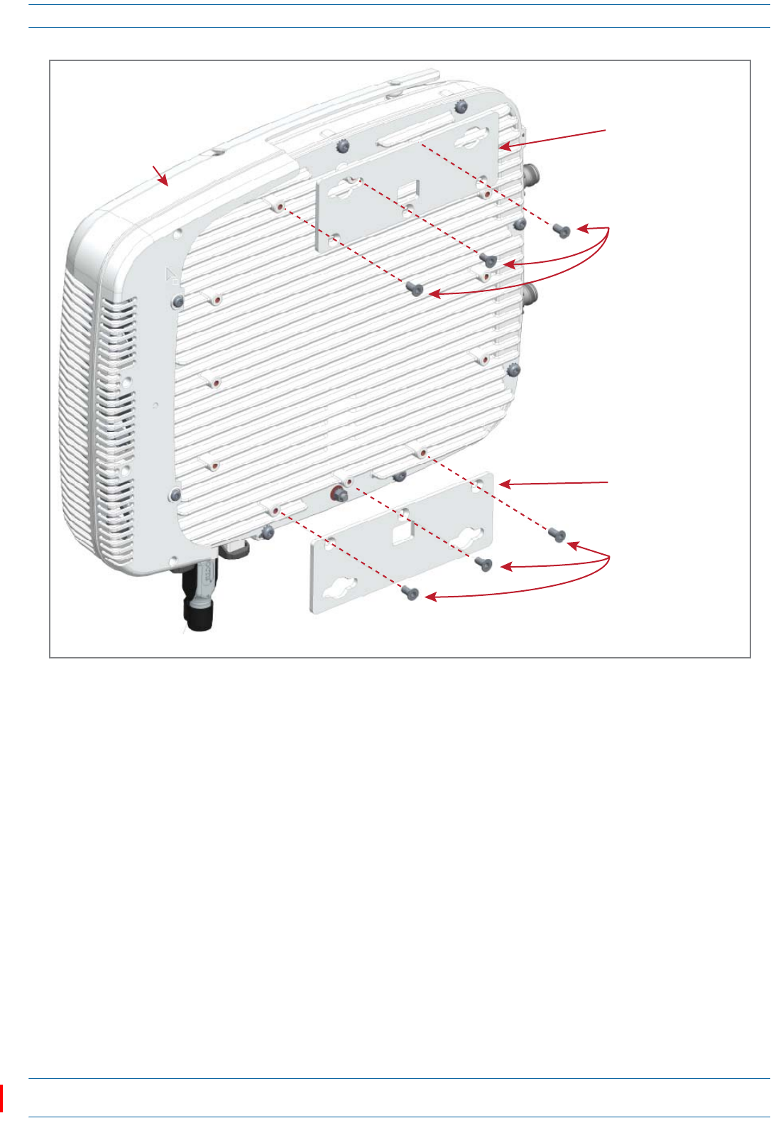
Figure 10. CAP L with a Fan Kit and Flat Mounting Bracket Kit (PN 7774353-xx)
6Usefour5/16-inchorM8lagscrews(orwhateverscrewtypeisappropriateforthematerialtowhichthe
CAPListomountedon)tomounttheCAPLtothewall.
7Followthestepsin"(Optional)GroundtheCAPL”onpage36ifgroundingisrequiredorpreferred.
8Followthestepsin"ConnecttheCAPLCables”onpage37.
One Mounng bracket
in vercal posion
Three
M6-1.0 x 14mm
screws
One Mounng bracket
in vercal posion
Three
M6-1.0 x 14mm
screws
NOTE: Install a CAP L that does not have a Fan Kit vercally.
Fan Kit
ION®-E Series Low Power Carrier Access Point Installation Guide M0201AAC
Page 28 © February 2018 CommScope, Inc.
Installing CAP Ls
Wall Mount a CAP L Using a CAP L Hybrid Fiber Splice Box Kit
1Followthestepsin"UnpackandInspecttheCAPLandOptionalAccessories”onpage22.
2Referto"DeterminetheCAPLMountingSite”onpage19todeterminethemountinglocation,whichmust
beabletosupporttheweightanddimensionsoftheCAPL.
3Referto"MountingOrientationforWallMounts”onpage24todeterminethemountingorientationofthe
CAPL.
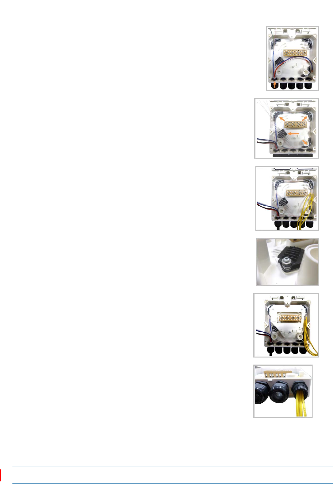
4AssemblethecablesintheHybridFiberSpliceBox.
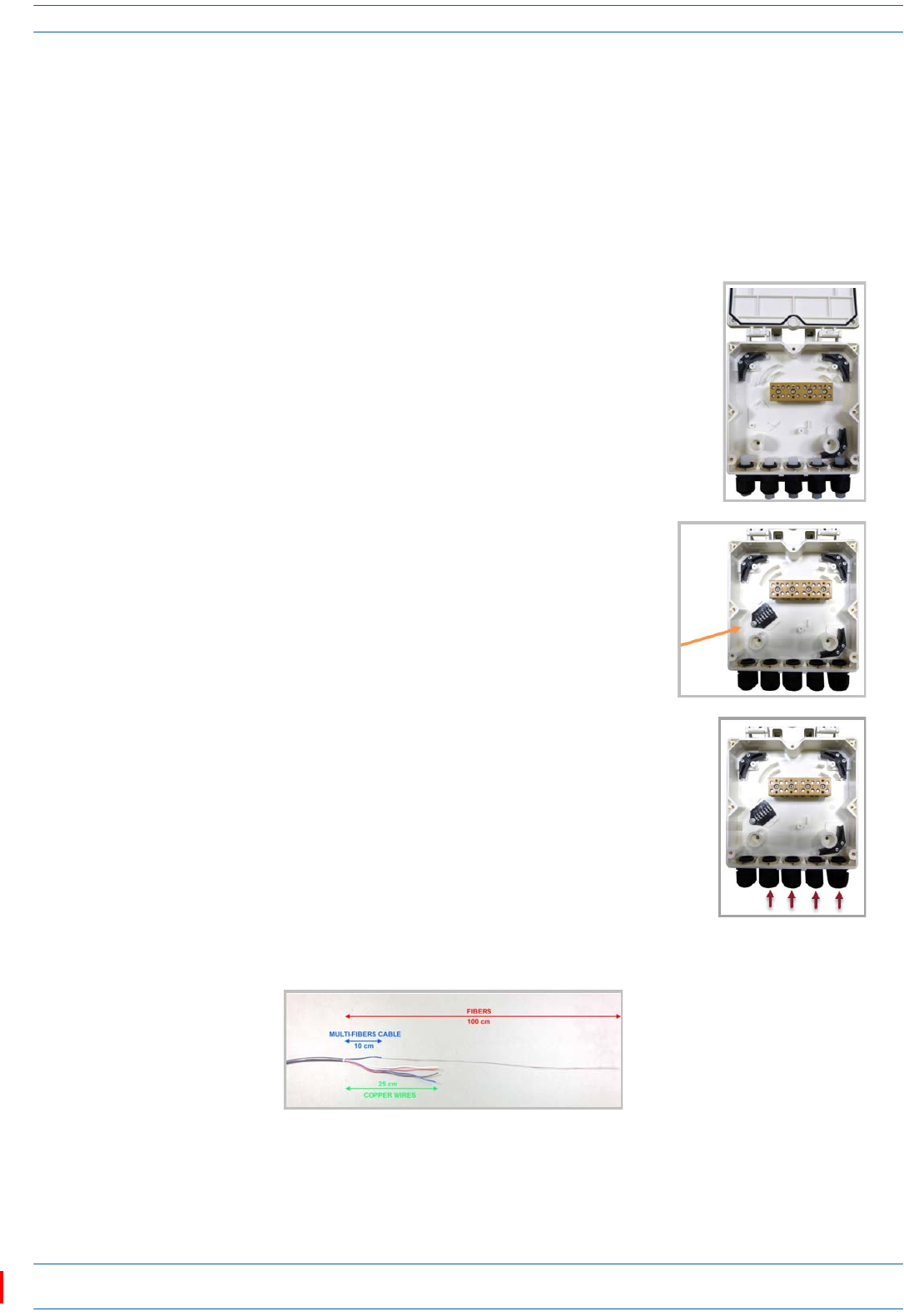
aOpentheHybridFiberSpliceBoxandremovetheinstallationkit
thatisinside.
bUsingthepartsfromtheHybridFiberSpliceBox,insertthe
SpliceHolderandfastenitusingaPTK30x6screwandoneM4
washer.
cFromtheCAPLHybridFiberSpliceBoxKit,insertFiberPatch
Cordinoneofthecableglandsindicatedinthegraphictothe
right.
dStriptheinsulationofthecompositecablefor100cmandthefibersfor90cm,andthenshorten
thecoppercablesto25cm.
M0201AAC ION®-E Series Low Power Carrier Access Point Installation Guide
© February 2018 CommScope, Inc. Page 29
Installing CAP Ls
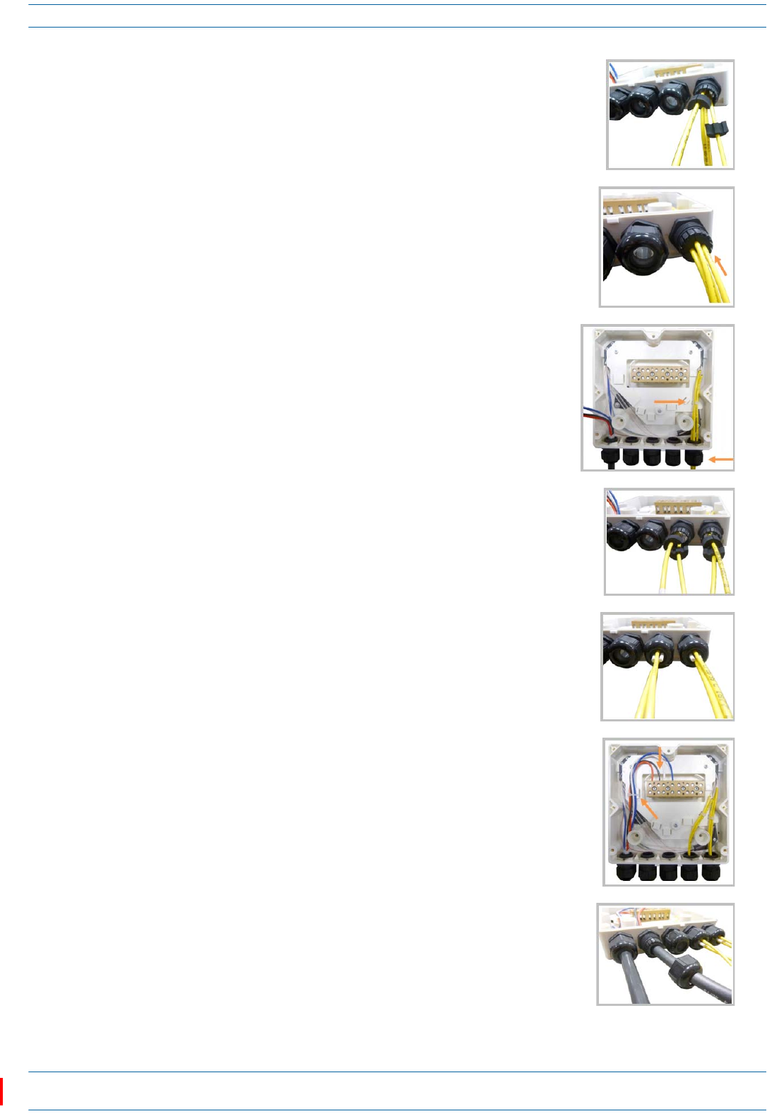
eInsertthecompositecableinthefirstcableglandandseparate
themulti-fiberscablefromthecopperwires.Itisnecessaryto
removethenuttoperformthisaction.Thecablemustbefed
throughthenutanditmustberetightenedoncefinished.
fBendthesplicedfibersusingthecornerguidesandfixthe
splicestothespliceholder.
gBendtheopticalcablesasshowinthepicturetotheright.
hIfasecondspliceholderisneeded,itcanbeassembledusingthe
M4insulatingwasherandtwoM4plainwashers,asshownto
theright.TherequiredscrewisaPTK30x12.
iMounttheinternalsupportSpliceBoxION-URUusingthree
PTK30x6screws.
jRemovethesealingnutandrubberofthecableglandandinsert
theopticalcables.
ION®-E Series Low Power Carrier Access Point Installation Guide M0201AAC
Page 30 © February 2018 CommScope, Inc.
Installing CAP Ls
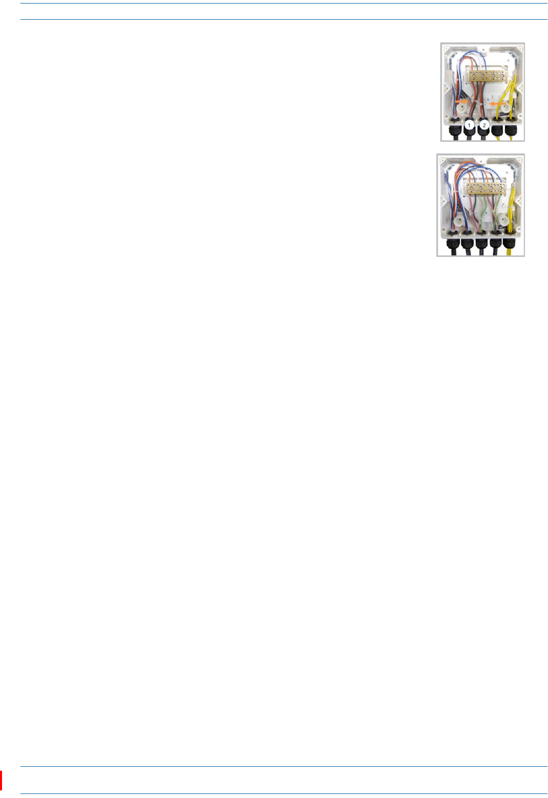
kPlaceeachcableintooneofthegroovesofthesealinsert.
lPressthesealinsertintotheclampringopening.
mFixtheopticalcablesinsidetheboxusingonecabletieandtight
thesealingnut.
nItispossibletoseparatetheopticalcablesandusetwodifferent
cableglands.Removethesealingnutandrubberoneachcable
gland.
oCloseallunusedgrooveswiththeplasticcylinders,nomatterif
oneortwocableglandsareused.
pInsertthecopperwiresinthefirstmultipleterminalconnectors.
Seemarkingsontheinternalsupport.Thenfastenthecopper
cablesinsidetheboxusingonecabletie.
qRemovethesealingnutandinserttheRemoteUnitsupplycable
andtightenthesealingnut.
M0201AAC ION®-E Series Low Power Carrier Access Point Installation Guide
© February 2018 CommScope, Inc. Page 31
Installing CAP Ls
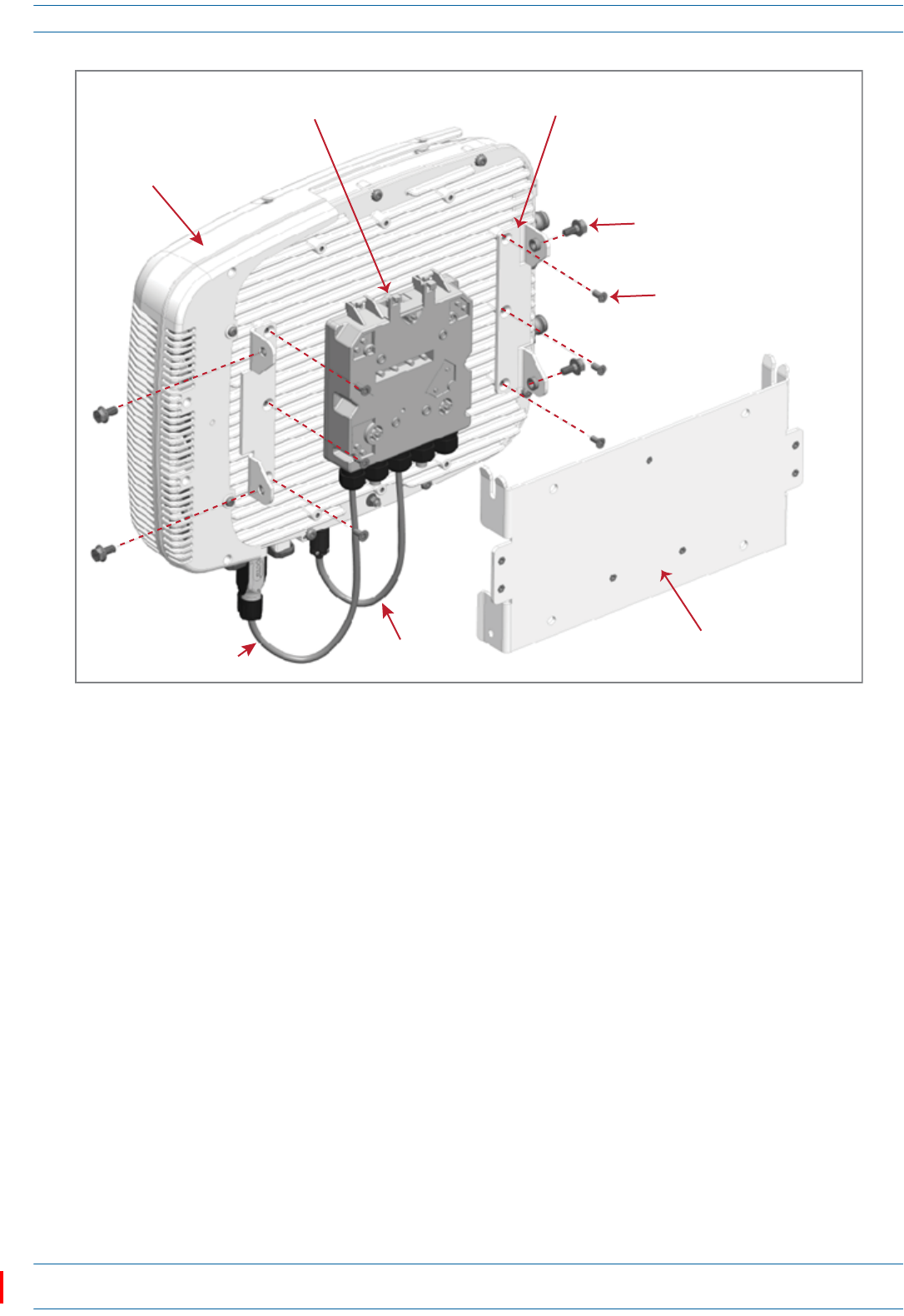
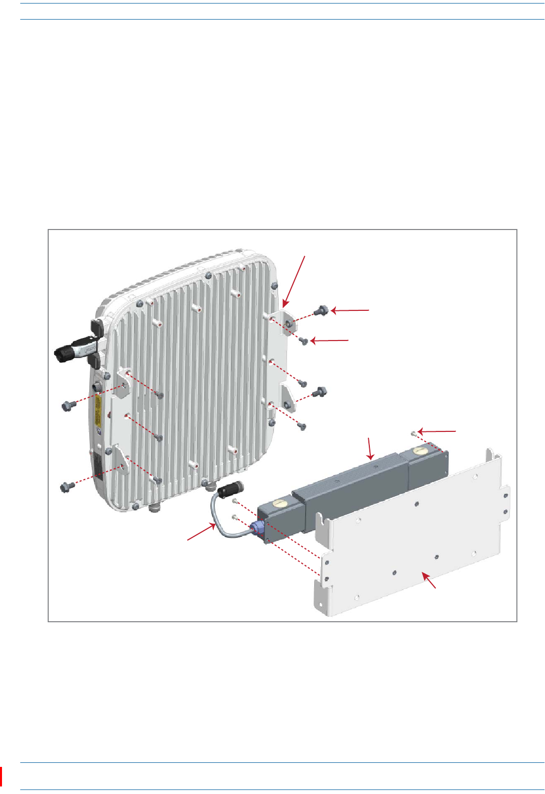
5AssembleandmounttheCAPLHybridFiberSpliceBoxKitandtheCAPL,asdescribedbelowandas
showninFigure11onpage32,whichshowsaCAPLwithFanKit(installationforaCAPLwithoutaFan
Kitisthesame).
aAttachtheHybridFiberSpliceBoxtotheWallBracketwiththethreecaptivescrewsalreadyinstalled
intheSpliceBox.
bAttachtheassembledHybridSpliceBoxandWallMountingBrackettotheselectedmountinglocation.
cUsethesixM6-1.0x14mmscrewstoattachthetwoAngledMountingBracketstotheWallMounting
Bracket.
iPutthetoptwoflange-headscrewshalfwayintothemountingbrackets,andthenusethemto
“hang”theCAPLintheWallMountingBracket.
ii Attachthebottomtwoflange-headscrews.
iii Tightenallfourscrews.
dFromtheCAPLHybridFiberSpliceBoxKit:
iAttachtheLocalPowerJumpertotheCAPLpowerconnector.
ii AttachtheFiberPatchCordtotheCAPLPort1;theotherendwasattachedinStep4c(page28)
tooneofthecableglands.
rConnectthesupplycabletotheterminalstripandfixitinsidethe
boxusingonecabletie.Itispossibletoconnectasecondsupply
cable.
sIncaseofusingremoteunitVdc/100connectthesupplycableas
shownbesides.Refertomarkingsontheinternalsupport.
ION®-E Series Low Power Carrier Access Point Installation Guide M0201AAC
Page 32 © February 2018 CommScope, Inc.
Installing CAP Ls
Figure 11. CAP L with Fan Kit, CAP L Mounting Bracket Kit, and CAP L Hybrid Fiber Splice Box Kit
6Followthestepsin"(Optional)GroundtheCAPL”onpage36ifgroundingisrequiredorpreferred.
7Followthestepsin"ConnecttheCAPLCables”onpage37.
Wall Mount a CAP L Using a AC/DC Power Supply Kit
1Refertoandobserveallcautionslistedin"GeneralMountingCautions”onpage21.
2Referto"DeterminetheCAPLMountingSite”onpage19todeterminethemountinglocation,whichmust
beabletosupporttheweightanddimensionsoftheCAPL.
3Referto"MountingOrientationforWallMounts”onpage24todeterminethemountingorientationofthe
CAPL.
4Followthestepsin"UnpackandInspecttheCAPLandOptionalAccessories”onpage22.
Two Angled
Mounng Brackets
Four M8x16 flange-head screws
Six M6-1.0 x 14mm screws
One Hybrid
Fiber Splice Box
One Wall Mounng Bracket
Fan Kit
One Local
Power Jumper
One Fiber
Patch Cord
M0201AAC ION®-E Series Low Power Carrier Access Point Installation Guide
© February 2018 CommScope, Inc. Page 33
Installing CAP Ls
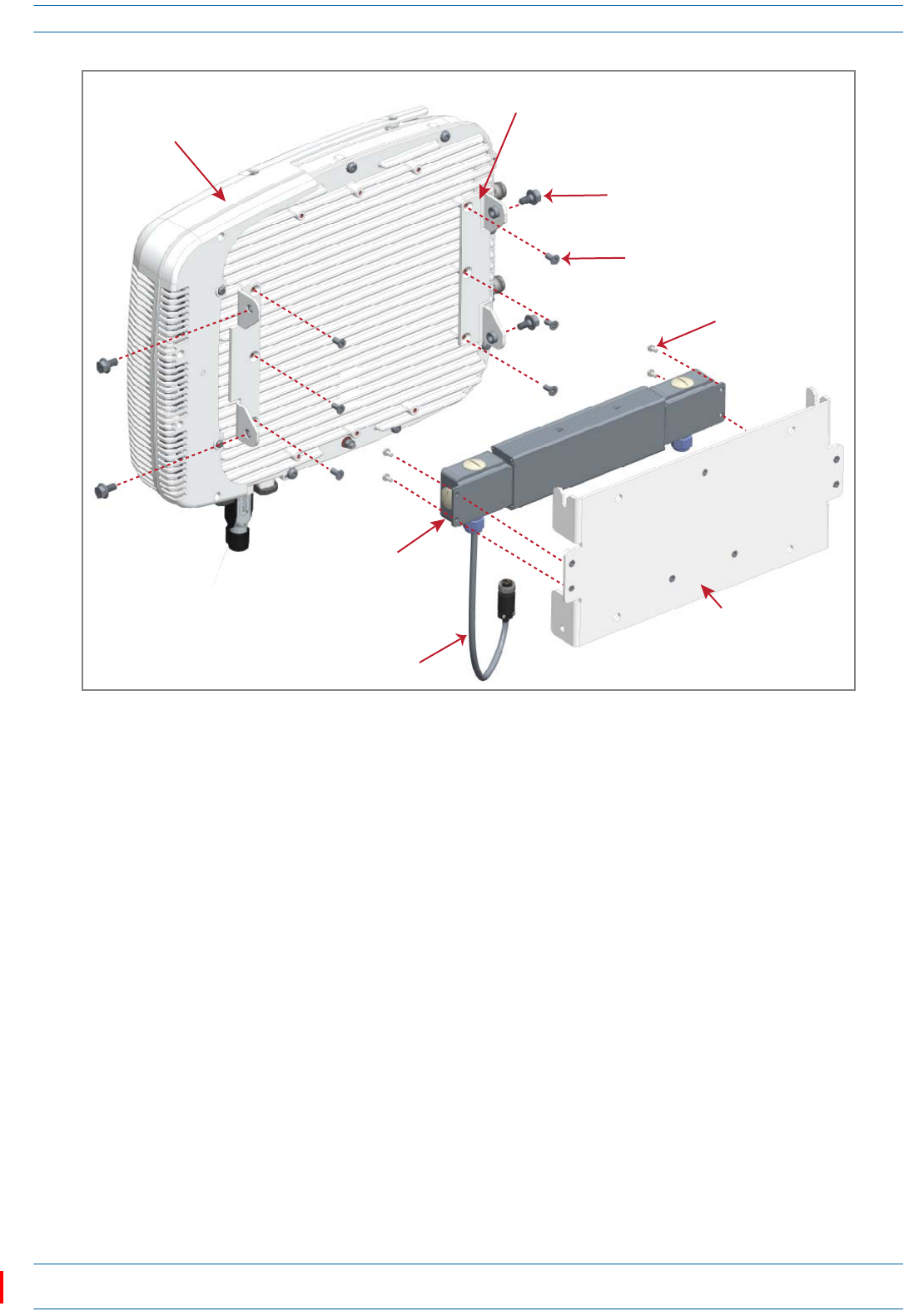
5AssembleandmounttheAC/DCPowerSupplyKitandtheCAPL,asdescribedbelowandasshownin
Figure12(CAPLwithoutFanKit)andFigure13onpage34(CAPLwithFanKit).TheLocalPower
JumperCableAssemblywillbeconnectedtotheAC/DCPowerSupplyJunctionBoxatthefactory.
aUsethefourscrewstoattachtheAC/DCPowerSupplyassemblytotheWallMountingBracket.
bAttachtheassembledAC/DCPowerSupplyKitandWallMountingBrackettotheselectedmounting
location.
cUsethesixM6-1.0x14mmscrewstoattachthetwoAngledMountingBracketstotheWallMounting
Bracket.
iPutthetoptwoflange-headscrewshalfwayintothemountingbrackets,andthenusethemto
“hang”theCAPLintheWallMountingBracket.
ii Attachthebottomtwoflange-headscrews.
iii Tightenallfourscrews.
Figure 12. CAP L (No Fan Kit) with AC/DC Power Supply Kit (PN 7775087-xx)
and CAP L Mounting Bracket Kit (7774354-xx)
Two Angled
Mounng Brackets
Four M8x16 flange-head screws
Six M6-1.0 x 14mm screws
Four
M6-1.0 x 14mm
screws
One Wall
Mounng Bracket
AC/DC Power Supply Unit
with Juncon Box
Local Power
Jumper Cable
ION®-E Series Low Power Carrier Access Point Installation Guide M0201AAC
Page 34 © February 2018 CommScope, Inc.
Installing CAP Ls
Figure 13. CAP L with Fan Kit and with AC/DC Power Supply Kit (PN 7775087-xx)
and CAP L Mounting Bracket Kit (PN 7774354-xx)
Two Angled
Mounng Brackets
Four M8x16 flange-head screws
Six M6-1.0 x 14mm screws
Four M4x8 screws
One Wall
Mounng Bracket
AC/DC Power
Supply Unit
with Juncon Box
Local Power
Jumper Cable
Fan Kit
M0201AAC ION®-E Series Low Power Carrier Access Point Installation Guide
© February 2018 CommScope, Inc. Page 35
Installing CAP Ls
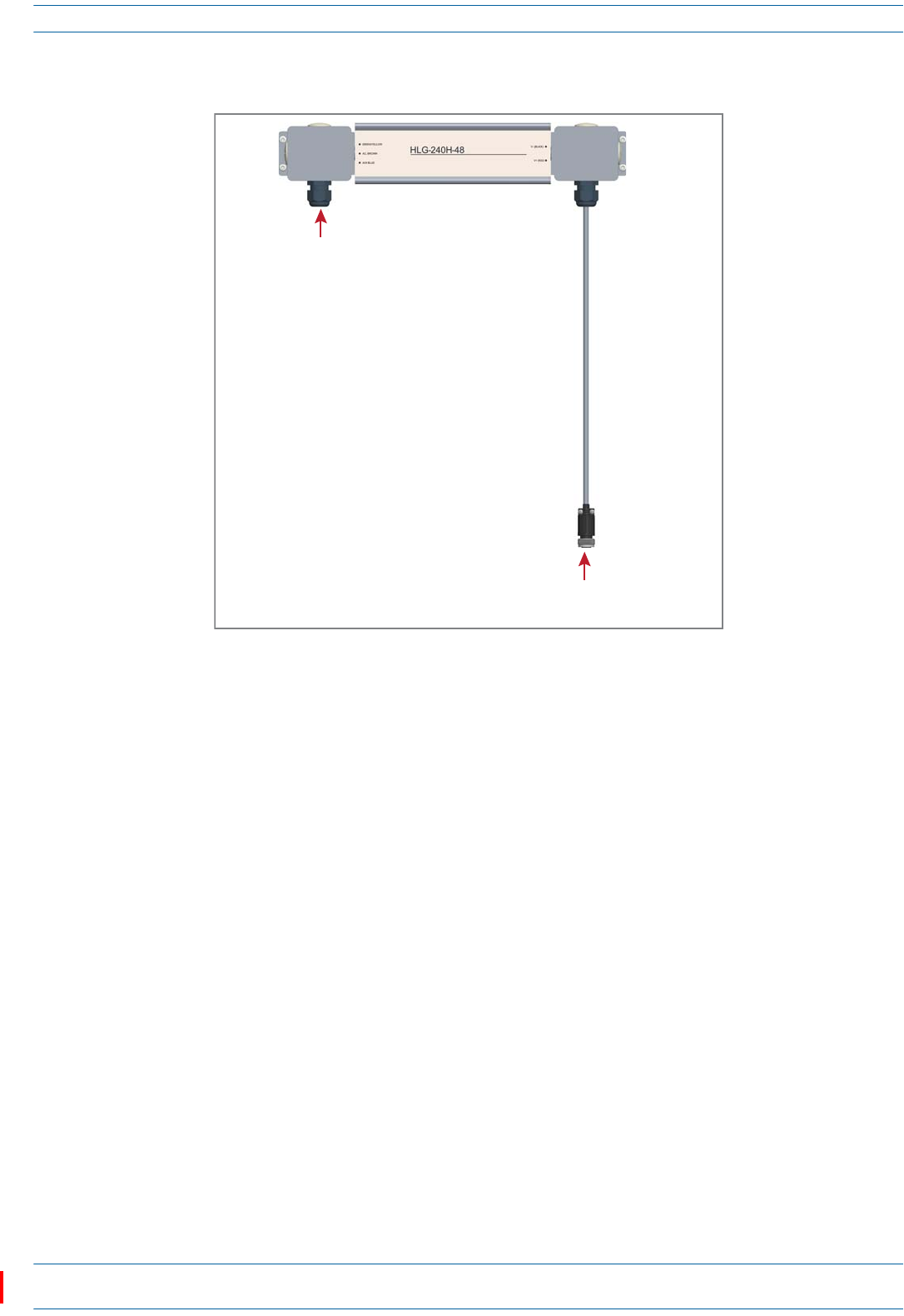
6ConnecttheLocalPowerJumperCable(shownbelow)totheCAPL36to60VdcPowerconnector(see
"CAPLwithaCopperInterfaceandPowerCat6ACable”onpage8).
7Followthestepsin"(Optional)GroundtheCAPL”onpage36ifgroundingisrequiredorpreferred.
8Followthestepsin"ConnecttheCAPLCables”onpage37.
Ceiling Mount a CAP L
YoucanmountaCAPLaboveorbelowaceiling.WheninstallingaCAPLbelowaceiling,theuseofthe
optionalFanKitdetermineshowtheCAPLcanbeceilingmounted,asdescribedinthefollowingsections.
•"CeilingMountaCAPLwithoutaFanKit”onpage35
•"CeilingMountaCAPLwithaFanKit”onpage35.
IfyoumounttheCAPLabovetheceiling,itsantennasmustprotrudebelowtheceiling.
Ceiling Mount a CAP L without a Fan Kit
ACAPLthatdoesnothaveaFanKitshouldonlybeinstalledaboveasuspendedceilingonaflatsurface,using
thestepsin"Flat-SurfaceMountaCAPL”onpage23.
Ceiling Mount a CAP L with a Fan Kit
1Followthestepsin"UnpackandInspecttheCAPLandOptionalAccessories”onpage22.
2Refertoandobserveallcautionslistedin"GeneralMountingCautions”onpage21.
3Referto"DeterminetheCAPLMountingSite”onpage19todeterminethemountinglocation,whichmust
beabletosupporttheweightanddimensionsoftheCAPL.
Local Power Jumper that connects
to CAP L 36 to 60 Vdc Power connector
Gland for incoming AC power
ION®-E Series Low Power Carrier Access Point Installation Guide M0201AAC
Page 36 © February 2018 CommScope, Inc.
Installing CAP Ls
4Followthestepsinoneofthefollowingsectionsthatapplytosecuringthedesiredmountingbracketto
theCAPL:
•"WallMountaCAPLUsingaFlatMountingBracketKit”onpage26
•"WallMountaCAPLUsingaCAPLHybridFiberSpliceBoxKit”onpage28
•"WallMountaCAPLUsingaAC/DCPowerSupplyKit”onpage32
5Usefour5/16-inchorM8lagscrews(orwhateverscrewtypeisappropriateforthematerialtowhichthe
CAPListomountedon)tomounttheCAPLtotheceiling.
6Followthestepsin"(Optional)GroundtheCAPL”onpage36ifgroundingisrequiredorpreferred.
7Followthestepsin"ConnecttheCAPLCables”onpage37.
(Optional) Ground the CAP L
FollowthestepsbelowtogroundtheOPAonlyifgroundingisrequiredinyourlocalityoriftheinstallation
plansrequiretheCAPLbegrounded.ThedifferentCAPLinstallationprocedureswilltellyouwhentoground
theCAPL.
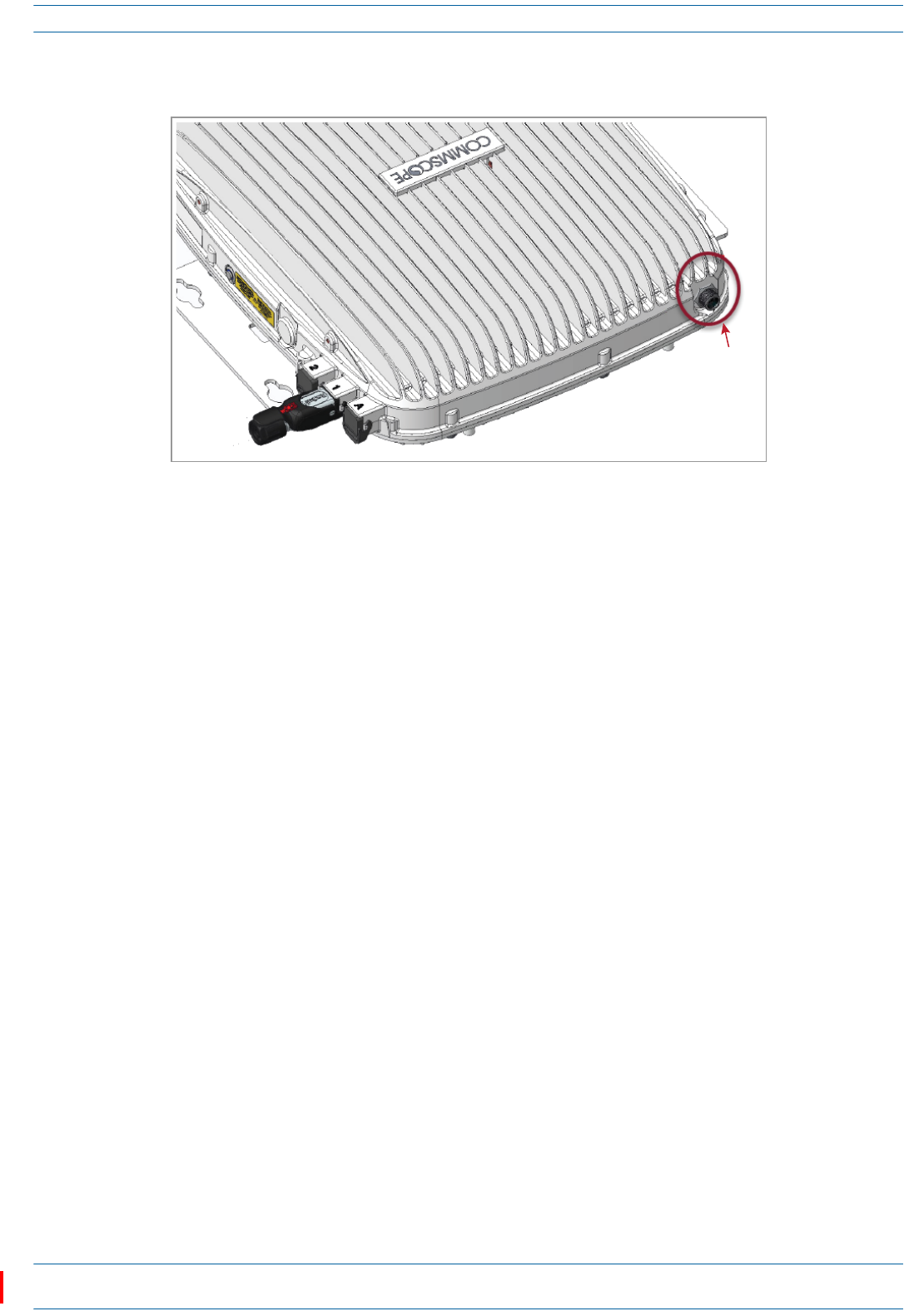
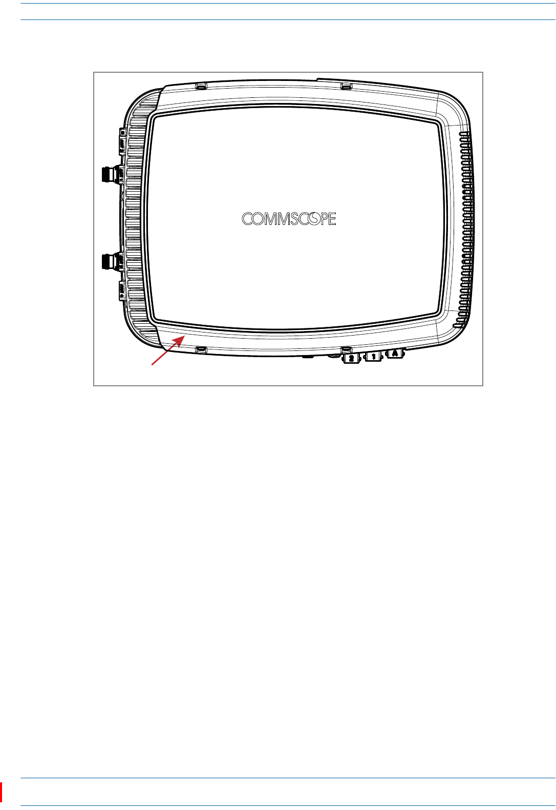
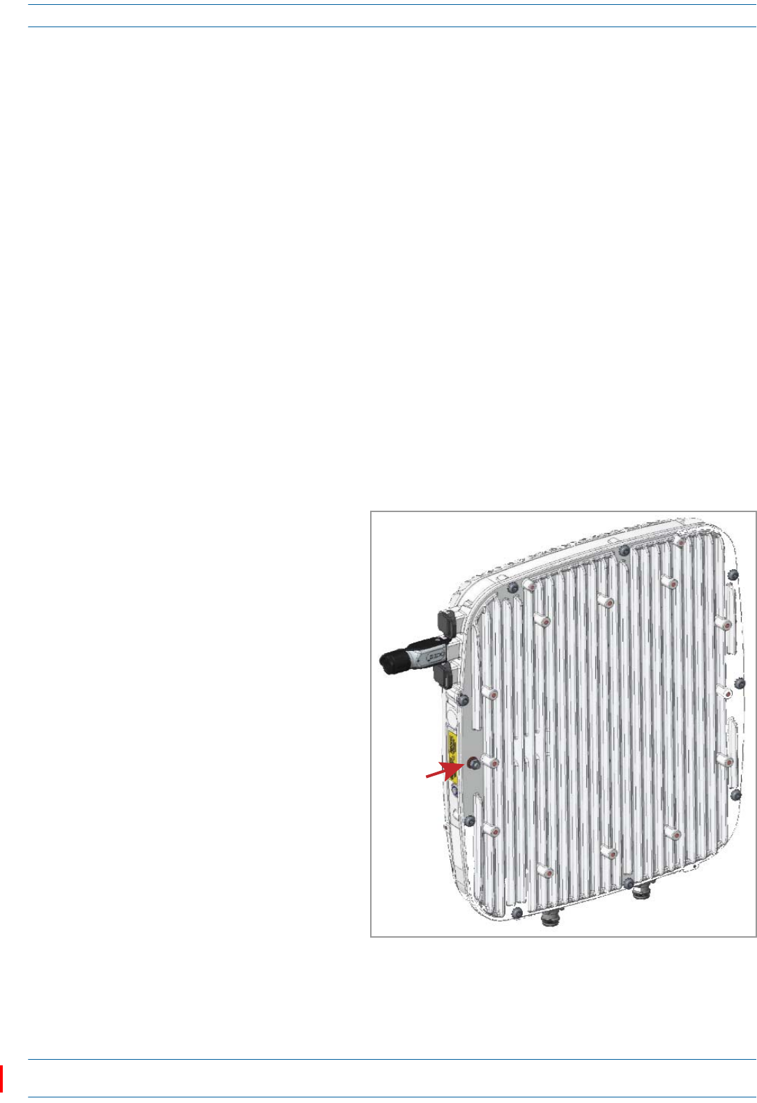
NOTE: The CAP L is equipped with an M6 grounding stud located on the back of the unit; however,
grounding is not necessary. CAP Ls are classified as low-voltage devices and do not have internal
power supplies. CommScope recommends checking your local and national electrical codes to
determine if grounding is a requirement.
1Obtainalengthof#18AWG(1.00mm)
insulatedstrandedcopperwireforuseas
achassis-groundingwire.
2Terminateoneendofthewirewitharing
terminal.
3Locatethechassis-groundstudattherear
oftheCAPLenclosure.
4RemovetheKepsnutfromthe
chassis-groundstud.
5Attachtheringendofthewiretothe
chassisgroundstud,asshowninthe
graphictotheright.
6UsetheKepsnutremovedinStep4to
securethegroundwiretothe
chassis-groundstud.
7Routethefreeendofthechassis
groundingwiretoanapproved(perlocal
codeorpractice)earthgroundsource.
Ground
stud
M0201AAC ION®-E Series Low Power Carrier Access Point Installation Guide
© February 2018 CommScope, Inc. Page 37
Installing CAP Ls
Connect the CAP L Cables
ThetypeofcablesusedandhowtheCAPLconnectsintothesystemisdependentontheCAPLtype.Follow
thecablinginstructionsthatapplytotheunittypethatyouareinstalling.
•"CableaCAPLwithanOpticalFiberInterface”onpage37
•"CableaCAPLwithaCopperInterface”onpage40.
Cable a CAP L with an Optical Fiber Interface
Figure14identifiestheconnectorsonaCAPLwithanOpticalFiberInterface;correspondingcablesand
connectorsareshown.Fordetailsontheports,see"CAPLwithanOpticalFiberInterface”onpage6.
Figure 14. Connectors on a CAP L with an Optical Fiber Interface
Do not remove caps from any of the connectors until instructed to do so.
ANT
1
ANT
2
Vdc
Power
connector
Opcal
Port 2
Opcal
Port 1
Auxiliary
port
ION®-E Series Low Power Carrier Access Point Installation Guide M0201AAC
Page 38 © February 2018 CommScope, Inc.
Installing CAP Ls
1ContactyourlocalCommScopesalesrepresentativetoobtainthefollowingcomponents,asrequired,for
thisinstallation.
•Pertheinstallationplan,obtaineitherSingleModeFiber(SMF)orMultiModeFiber(MMF)thatisof
sufficientlengthtoreachfromtheCAPLtotheION-ECAN/TEN
•ObtainatleastoneOpticalOCTISKit(PN7770612).AllinstallationsrequireoneOpticalOCTISKit.If
cascadingaSecondaryCAPL,asecondOpticalOCTISKitisrequired.
•ObtainanSFP+Modulethatisappropriateforthisinstallation.Table7identifiestheavailableSFP+
Modulesandthemaximumrangeforeach.
•IfconnectinganexternalEthernetdevicesuchasWiFiorIPcamera,anEthernetOCTISKit
(PN7760652RJ-45)andappropriateCATcablefortheprotocoltowhichtheCAPLwillconnect.(This
modelsupportsa1000BASE-Tand802.3atClass4PoweroverCat6AEthernetconnection.Follow
therulesin"Cat6ACableRequirementsforCAPLswithaCopperInterface”onpage40,allCat6Acable
requirementsandcable-lengthrulesbetweenaPrimaryandSecondaryCAPLalsoapplyto
connectinganexternalEthernetdevice.)
–AsingleCAPLcansupportoneauxiliaryEthernetdevice.
–AcascadedCAPLpaircansupportoneauxiliarydevice.
2ConnecttheCAPLANT1and/orANT2connectortoapassiveRFantenna.
aObtain50ΩcoaxialcablesthatareofsufficientlengthtoreachfromtheCAPLtothepassiveantenna.
Theendofthe50ΩcoaxialcablethatwillconnecttotheANTconnectorcanbeeitherapush-pull
connectororathreadedconnector.
bInstallthepassiveantennasperthemanufacturer’sinstallationinstructions.IfconnectingbothANT
connectors,youwillconnecttheCAPLtoeithertwoseparateexternalpassiveantennasortotwo
portsonacross-polarizeddualantenna.EachconnectorsupportstwoRFbands(seeTable8).
cRemovetheIP67/EMIblankplugfromtheANT1/2connector.
dConnectthepassivemulti-bandantennatotheANT1orANT2connectorusingcoaxialcablewiththe
leastamountoflosspossible.
•Ifthe50Ωcoaxialcablehasapush-pullconnector,makesurethecableisseatedfirmlyintheANT
1orANT2connector.
•Ifthe50Ωcoaxialcablehasathreadedconnector,torquetheconnector5N-m(3.69ft-lb).Donot
over-tightentheconnector.
eConnecttheotherendofthe50ΩcoaxialcabletothepassiveantennainstalledinStepbonpage38.
Table 7. Supported SFP+ Modules
CommScope PN Description Maximum Range Notes
7660511 ION-E SFP+, 10GBase-SRR, Multi Mode OM3 OM4
300m 400m
One placed in the TEN and paired with another in the CAN
7680813 ION-E SFP+, 10GBase-LR, Single Mode 10km One placed in the TEN and paired with another in the CAN
Table 8. Mapping Frequency Bands to Antennas
Frequency Band Band Combination Antenna Port
AWS1700 / LTE2300 17E and 23 1
AWS1700 / LTE2300 17E and 23 2
GSM1800 / UMTS2100 / LTE2600 18 and 26 1
GSM1800 / UMTS2100 / LTE2600 21 and 26 2
AWS1700 / PCS1900 17E and 19 1
AWS1700 / PCS1900 17E and 19 2
M0201AAC ION®-E Series Low Power Carrier Access Point Installation Guide
© February 2018 CommScope, Inc. Page 39
Installing CAP Ls
3Ifnecessary,repeatStep2onpage38toconnecta50ΩcoaxialcabletotheotherANTconnector.
4ConnecttheCAPLOpticalPort1asappropriateforthisinstallation.Notethemaximumrangelistedin
Table6onpage19.
aRemovethedustcapfromtheCAPLOpticalPort1connectorandtheconnectorsontheSMForMMF.
bFollowthelocalcleaningtechniquetocleanOpticalPort1.
cCleantheconnectorsontheSMForMMFfollowingthefibersupplier’srecommendations.
dInstalltheSFP+connectorandOpticalOCTISKitontheendoftheSMForMMFthatwillconnectto
theCAPL,andthenconnectthatendofthefibertotheCAPLOpticalPort1connector.(Refertothe
technicaldatasheetthatshipswiththeOCTISKitforfurtherinformation.)
eConnecttheotherendoftheSMForMMFtoanopenportontheOPTCard.
5Ifappropriateforthisinstallation,connecttheOpticalPort2connector.Notethemaximumrangelisted
inTable6onpage19.
aRaisetheleverontheEMI/IP67caponOpticalPort2connectorandremovethecap.
bRemovethecapsfromtheconnectorsontheSMForMMF.
cFollowthelocalcleaningtechniquetocleanOpticalPort2.
dCleantheconnectorsontheSMForMMFfollowingthefibersupplier’srecommendations.
eInstalltheSFP+andOpticalOCTISKitontheendofthefiberthatwillconnecttotheCAPL,and
connectthatendoftheSMForMMFtotheCAPLOpticalPort2connector.(Refertothetechnicaldata
sheetthatshipswiththeOCTISKitforfurtherinformation.)
fConnectotherendoftheSMForMMFtoOpticalPort1onthecascadedCAPL.
6(Optional)PortA(Auxiliaryport)providesaconnectionforexternalEthernetdevicessuchasWiFiand
IPcameras.CablePortAasappropriateforthisinstallation.
aRaisetheleverontheEMI/IP67caponPortAandremovethecap.
bInstalltheEthernetOCTISKitontheendofthecablethatwillconnecttotheCAPL,andthenconnect
thatendofthecabletoCAPLPortA.(RefertothetechnicaldatasheetthatshipswiththeOCTISKit
forfurtherinformation.)
cConnecttheotherendoftheCATcabletotheEthernetportoftheauxiliarydevice.
If installing a CAP L with the CAP L Hybrid Fiber Splice Box Kit (PN 7774354-xx), the optical fiber will be
hanging from the Hybrid Fiber Splice Box.
Port A must be plugged if not in use.
This cable cannot exceed 3 meters (9.8 feet).

ION®-E Series Low Power Carrier Access Point Installation Guide M0201AAC
Page 40 © February 2018 CommScope, Inc.
Installing CAP Ls
7ConnecttheVdcPowerconnectorasappropriateforthisinstallation.
•ForaCAPLwithnolocalpowersupplyandnohybridfibercable,connectapowercable(notsupplied
byCommScope)totheproprietary4-pin,36to60VdcPowerconnectorontheCAPL.
•ForaCAPLpoweredbytheCAPLHybridFiberSpliceBoxKit(PN7774354-xx)connectthe:
–powercabletheproprietary4-pin,36to60VdcPowerconnectorontheCAPL,andterminatethe
otherendtotheCAPLHybridFiberSpliceBox
–LCFiberJumpertothesuppliedOCTISconnector,andsplicetheotherendofthefiberjumpers
insidethelocally-mountedCAPLHybridFiberSpliceBox.
•ForaCAPLwiththeoptionalAC/DCPowerSupplyKit(PN7775087-xx),connectitsLocalPower
JumperCableAssemblytotheproprietary4-pin,36to60VdcPowerconnectorontheCAPL.
TheCAPLispoweredonassoonasyouconnecttheCAPLtoapowersource;see"PoweringaCAPL”on
page48.
Cable a CAP L with a Copper Interface
AllinstallationsofaCAPLwithaCopperInterfacemustfollowtherulesin"Cat6ACableRequirementsfor
CAPLswithaCopperInterface”onpage40.Followthecablinginstructionsthatapplytotheunittypethat
youareinstalling.
•"CableaCAPLwithaCopperInterfaceandExternalDCPower”onpage43
•"CableaCAPLwithaCopperInterfaceandPoweroverCat6ACable”onpage45.
Cat6A Cable Requirements for CAP Ls with a Copper Interface
ThefollowingcablingrulesmustbeobservedforallinstallationsofaCAPLwithaCopperInterface.
•Plenumratedcablemustbeusedwhereveritisrequiredbylocalelectricalcodes.
•ShieldedtwistedpairisnotrequiredunlessoperatinginahighRFI/EMIenvironment.
•AnION-EsystemrequiresaminimumSignal-to-NoiseRatio(SNR)of25dB,andAlienCrosstalk(AXT)
mustnotdegradeSNRonanycablebymorethan0.5dB.
•Cat6Acablewiresizerequirementsareasfollows:
–23AWGCat6Acable(minimumEIA/TIAstandards)mustbeusedbetweenRJ-45connectorpoints
–24AWGistheminimumwiresizeallowedforaCat6APatchCord.
•CommScopestronglyrecommendsusingfactoryterminatedandtestedCat6APatchCord.
For information on how to test your Cat6A cables and connections, see "Cat6A Specifications and Testing
Requirements” on page 50.
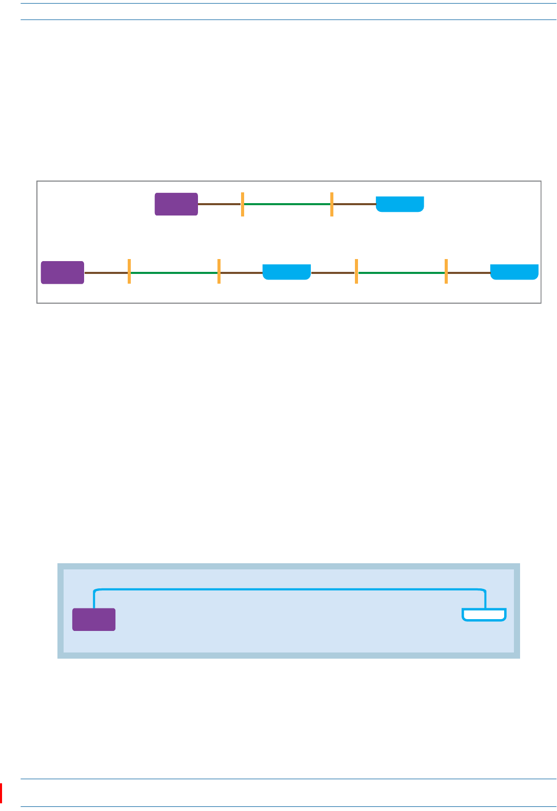
M0201AAC ION®-E Series Low Power Carrier Access Point Installation Guide
© February 2018 CommScope, Inc. Page 41
Installing CAP Ls
•TherecanneverbemorethantwoRJ-45connectionsinaCat6Acablerun,asdescribedbelowandas
showninFigure15.Minimizingtheseconnectionsimprovesthelinkmargin.
–Inanon-cascade,betweentheCATCardandtheAP,therecanbe
oneCat6APatchCordatthestartofaCat6Acablerun
asecondCat6APatchCordattheendofaCat6Acablerun.
–Inacascade,betweenthePrimaryAPandtheSecondaryAP,therecanbe
oneCat6APatchCordatthestartofaCat6Acablerun
asecondCat6APatchCordattheendofaCat6Acablerun.
Figure 15. Maximum Number of RJ-45 Connections in Cable Runs
•UnshieldedCat6A(Category6AU/UTP)twistedpaircablethatmeetsANSI/TIA-568-C.2,CENELECEN
50173series,andISO/IEC11801:2002includingitsamendments1and2,issuitableforuseinanION-E
system.TheCommScopeGigaSPEEDX10D®2091BETLVerifiedCategory6AU/UTPCable(760107201,
2091BBL4/23W1000)meetstheserequirementsandisrecommended.
TherearemanyparametersthatimpacttheSNRofthe10GBase-TsignalreceivedbytheCATCardfrom
theAP,orreceivedbytheAPfromtheCATCard.Forexample,excessiveinsertionlossdegradesthesignal
level,whichresultsinadegradedSNR.AnincreaseinthenoiselevelwillalsoresultindegradedSNR.The
mostcommonsourcesofnoiseareNEXT(nearendcrosstalk,interferencefrompairswithinacablethat
couplefromtheTXtoRX),andAXT(aliencrosstalk,interferencefromadjacentcables).Additionally,
therecanbeinterferencefromoutsidesourcessuchaslighting,switchingpowersupplies,radio
transmittersintheUHFandVHFbands,andsimilarsourcesofRFI/EMI.ToguaranteeacceptableSNR
level,allcablekeyparametersmustbemeasuredasdiscussedinthenextsection.
•ThemaximumCat6AcablelengthbetweenaCAPLwithaCopperInterfaceandaCAN/TENis100meters
includingallCat6Acables,Cat6APatchCords,andPatchPanels(seeFigure16).Nomorethan5mof
Cat6APatchCordsshouldbeusedtoconnecttheCATCardandaCAPLwithaCopperInterface.
Figure 16. Maximum Cat6A Cable Lengths from CAT Card to CAP L
CAP L
RJ-45
connecon
≥ 24 AWG
Cat6A
Patch Cord
23 AWG
Cat6A
Cable
RJ-45
connecon
CAT Card
in CAN/TEN
≥ 24 AWG
Cat6A
Patch Cord
CAT/TEN
Secondary
CAP L
RJ-45
connecon
CAT Card
in CAN/TEN
≥ 24 AWG
Cat6A
Patch Cord
≥ 24 AWG
Cat6A
Patch Cord
≥ 24 AWG
Cat6A
Patch Cord
≥ 24 AWG
Cat6A
Patch Cord
23 AWG
Cat6A
Cable
23 AWG
Cat6A
Cable
Primary
CAP L
RJ-45
connecon
RJ-45
connecon
RJ-45
connecon
Note: References to Cat6A is inclusive of all Cat6A Cables, Cat6A Patch Cords, and Patch Panels
From the CAT/TEN to the CAP L, Cat6A cannot exceed 100 meters.
CAT Card
in CAN/TEN
CAP L
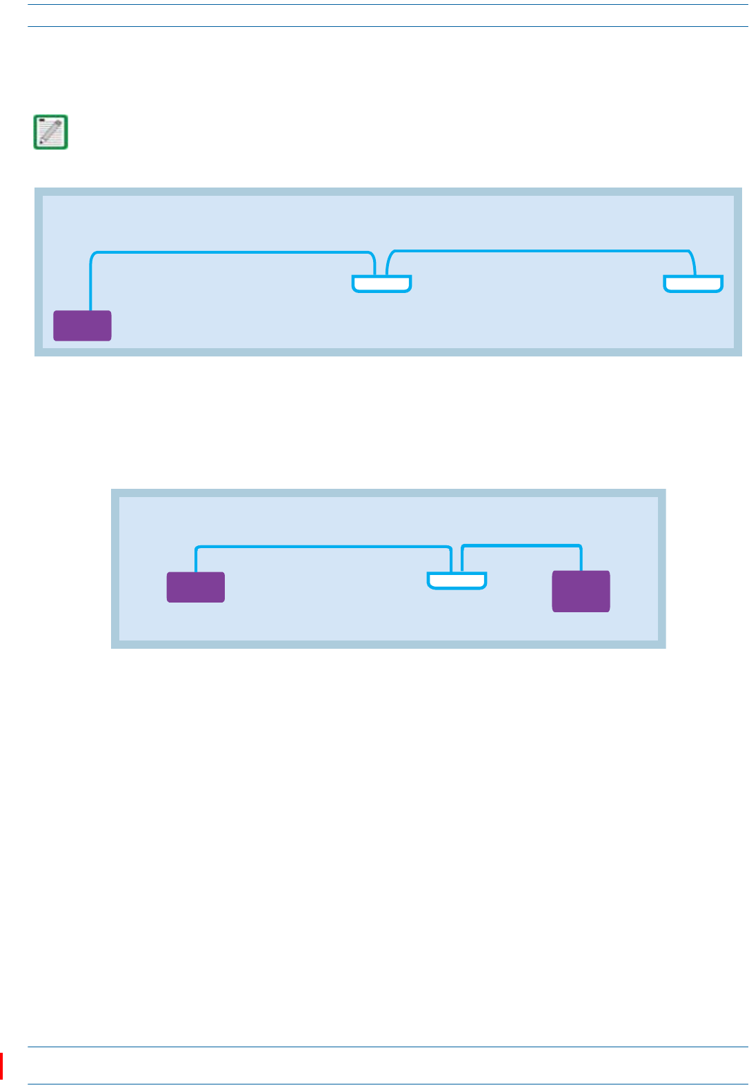
ION®-E Series Low Power Carrier Access Point Installation Guide M0201AAC
Page 42 © February 2018 CommScope, Inc.
Installing CAP Ls
•ForcascadedCAPLs,themaximumCat6AcablelengthbetweentheAUXportonthePrimaryCAPLand
theMAINportontheSecondary(cascaded)CAPL,includingthelengthoftheCat6APatchCord,mustbe
lessthan100meters(seeFigure17).
Figure 17. Maximum Cat6A Cable Lengths between Cascaded CAP Ls
•ThemaximumCat6AcablelengthbetweentheAUXportontheCAPLandanauxiliaryEthernetdeviceis
10meters,includingallCat6Acables,Cat6APatchCords,andPatchPanels,asshowninFigure18.24
AWGCat6Acablingissufficientfortheentirecablerun,fromtheCAN/TENtotheauxiliaryEthernet
deviceconnection.
Figure 18. Maximum Cat6A Cable Length between a CAP L and an Ethernet Device
The Secondary CAP L must get its power through the DC connector (either from a local supply or hybrid
fiber); power over the Cat6A cable to the cascaded unit is not supported. See "Cascade Rules” on page 17.
Note: References to Cat6A is inclusive of all Cat6A Cables, Cat6A Patch Cords, and Patch Panels
SecondaryPrimary
Cable Run A
from the CAT/TEN to the Primary CAP L
Cat6A cannot exceed 100 meters
Cable Run B
from the Primary CAP L to the Secondary CAP L
Cat6A cannot exceed 100 meters
CAP L CAP L
CAT Card
in CAN/TEN
Note: References to Cat6A is inclusive of all Cat6A Cables, Cat6A Patch Cords, and Patch Panels.
From the CAP L to an auxiliary
Ethernet device, Cat6A
must be ≤ 10 meters
From the CAT/TEN to the CAP L,
Cat6A cannot exceed 100 meters
CAT Card
in CAN/TEN
CAP L
Auxiliary
Ethernet
Device
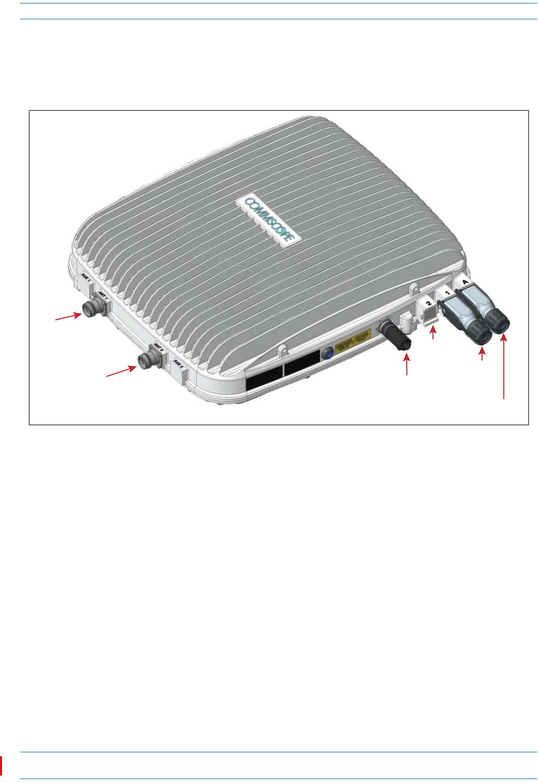
M0201AAC ION®-E Series Low Power Carrier Access Point Installation Guide
© February 2018 CommScope, Inc. Page 43
Installing CAP Ls
Cable a CAP L with a Copper Interface and External DC Power
Figure19identifiestheconnectorsonaCAPLwithaCopperInterfacethatispoweredbyanexternalpower
source;correspondingcablesandconnectorsareshown.Fordetailsontheports,see"CAPLwithaCopper
InterfaceandExternalDCPower”onpage7.
Figure 19. Connectors on a CAP L with a Copper Interface with External DC Power
DothefollowingtoinstallaCAPLwithaCopperInterfacethatispoweredbyanexternalpowersource.
1Obtainthefollowingcomponents,asrequiredforthisinstallation.
•50ΩcoaxialcablethatisofsufficientlengthtoreachfromtheCAPLtothepassiveantenna.Theend
ofthe50ΩcoaxialcablethatwillconnecttotheANTconnectorcanbeeitherapush-pullconnectoror
athreadedconnector.
•Followingtherulesin"Cat6ACableRequirementsforCAPLswithaCopperInterface”onpage40,
obtainCat6AcablethatisofsufficientlengthtoreachfromtheCAPLtotheION-ECAN/TEN.
•AllinstallationsrequireoneEthernetOCTISKit(PN7760652RJ-45).AdditionalEthernetOCTISKits
arerequired(oneeach)forcascadingaSecondaryCAPLand/orconnectinganexternalEthernet
devicesuchasWiFioranIPcamera.
•IfconnectingtoanexternalEthernetdevicesuchasWiFioranIPcamera,obtaintheappropriateCAT
cablefortheprotocoltowhichtheCAPLwillconnect.Thismodelsupportsa1000BASE-Tand
802.3atClass4PoweroverCat6AEthernetconnection.
–AsingleCAPLcansupportoneauxiliaryEthernetdevice.
–AcascadedCAPLpaircansupportoneauxiliarydevice.
–Followtherulesin"Cat6ACableRequirementsforCAPLswithaCopperInterface”onpage40,all
Cat6Acablerequirementsandcable-lengthrulesbetweenaPrimaryandSecondaryCAPLalso
applytoconnectinganexternalEthernetdevice.
ANT
1
ANT
2Vdc
Power
connector
Cat6A
Port
1
Auxiliary
port
Port
2
ION®-E Series Low Power Carrier Access Point Installation Guide M0201AAC
Page 44 © February 2018 CommScope, Inc.
Installing CAP Ls
2ConnecttheCAPLANT1and/orANT2connectortoapassiveRFantenna.
aInstallthepassiveantennasperthemanufacturer’sinstallationinstructions.IfconnectingbothANT
connectors,youwillconnecttheCAPLtoeithertwoseparateexternalpassiveantennasortotwo
portsonacross-polarizeddualantenna.EachconnectorsupportstwoRFbands(seeTable1on
page1).
bRemovetheplastic-protectivecapfromthe4.3-10connectors.
cRemovetheIP67/EMIblankplugfromANT1/2connector.
dConnectthepassivemulti-bandantennatotheANT1orANT2connectorusingcoaxialcablewiththe
leastamountoflosspossible.
•Ifthe50Ωcoaxialcablehasapush-pullconnector,makesurethecableisseatedfirmlyintheANT
1orANT2connector.
•Ifthe50Ωcoaxialcablehasathreadedconnector,torquetheconnector5N-m(3.69ft-lb).Donot
over-tightentheconnector.
eConnecttheotherendofthe50ΩcoaxialcabletothepassiveantennainstalledinStepa.
3Ifnecessary,repeatStep2toconnecta50ΩcoaxialcabletotheotherANTconnector.
4ConnecttheCAPLPort1connectorasappropriateforthisinstallation.
aRemovethedustcapfromthePort1connector.
bInstalltheEthernetOCTISKitontheendofthecablethatwillconnecttotheCAPL.(Refertothe
technicaldatasheetthatshipswiththeOCTISKitforfurtherinformation.)
cConnectoneendoftheCat6AcabletothePort1connectorandtheotherendtoanavailableporton
aCATCardintheCAN/TEN.
5(Optional)PortA(Auxiliaryport)providesacascadeconnectiontoanoptionallocallypoweredcascaded
CAPL,orprovidesaconnectiontoexternalEthernetdevicessuchasWiFiandIPcameras.CablePortAas
appropriateforthisinstallation.
aRaisetheleverontheEMI/IP67caponPortAandremovethecap.
bInstalltheEthernetOCTISKitontheendofthecablethatwillconnecttotheCAPL,andthenconnect
thatendofthecabletoCAPLPortA.(RefertothetechnicaldatasheetthatshipswiththeOCTISKit
forfurtherinformation.)
cConnecttheotherendoftheCATcabletotheEthernetportoftheauxiliarydevice.
Port 2 is plugged as it is not used in this configuration.
Port A must be plugged if not in use.
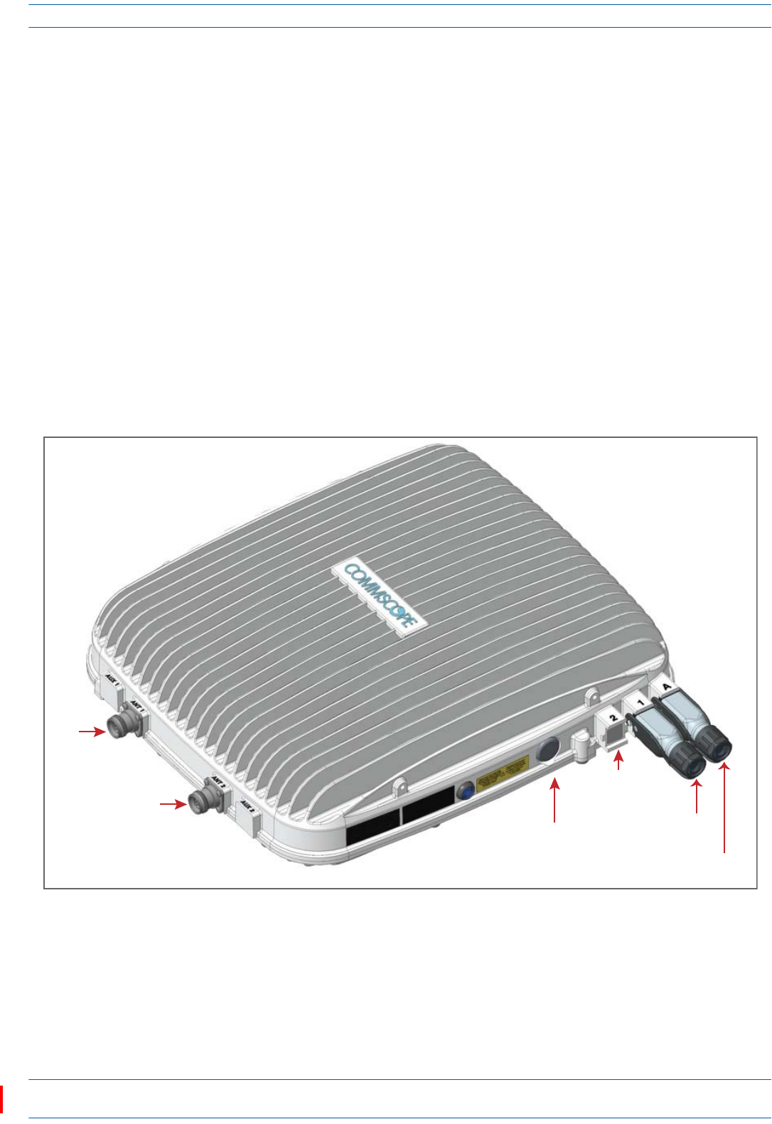
M0201AAC ION®-E Series Low Power Carrier Access Point Installation Guide
© February 2018 CommScope, Inc. Page 45
Installing CAP Ls
6ConnecttheVdcPowerconnectorasappropriateforthisinstallation.
•ForaCAPLwithnolocalpowersupplyandnohybridfibercable,connectapowercable(notsupplied
byCommScope)totheproprietary4-pin,36to60VdcPowerconnectorontheCAPL.
•ForaCAPLpoweredbytheCAPLHybridFiberSpliceBoxKit(PN7774354-xx),connectthe:
–powercabletotheproprietary4-pin,36to60VdcPowerconnectorontheCAPL,andterminate
theotherendintheHybridFiberSpliceBox
–LCFiberJumpertothesuppliedOCTISconnector,andsplicetheotherendofthefiberjumpers
insidethelocally-mountedCAPLHybridFiberSpliceBox.
•ForaCAPLwiththeoptionalAC/DCPowerSupplyKit(PN7775087-xx),connectitsLocalPower
JumperCableAssemblytotheproprietary4-pin,36to60VdcPowerconnectorontheCAPL.
TheCAPLispoweredonassoonasyouconnecttheLocalPowerJumperCableAssemblytoapower
source;see"PoweringaCAPL”onpage48.
Cable a CAP L with a Copper Interface and Power over Cat6A Cable
Figure20identifiestheconnectorsonaCAPLwithCopperInterface;correspondingcablesandconnectors
areshown.Fordetailsontheports,see"CAPLwithaCopperInterfaceandPowerCat6ACable”onpage8.
Figure 20. Connectors on a CAP L with a Copper Interface
ANT
1
ANT
2
Vdc
Power
connector Auxiliary
port
Cat6A
Port 1
Port
2

ION®-E Series Low Power Carrier Access Point Installation Guide M0201AAC
Page 46 © February 2018 CommScope, Inc.
Installing CAP Ls
DothefollowingtoinstallaCAPLwithaCopperInterfacethatispoweredoveraCat6Acable.
1Obtainthefollowingcomponents,asrequiredforthisinstallation.
•50ΩcoaxialcablethatisofsufficientlengthtoreachfromtheCAPLtothepassiveantenna.Theend
ofthe50ΩcoaxialcablethatwillconnecttotheANTconnectorcanbeeitherapush-pullconnectoror
athreadedconnector.
•Followingtherulesin"Cat6ACableRequirementsforCAPLswithaCopperInterface”onpage40,
obtainCat6AcablethatisofsufficientlengthtoreachfromtheCAPLtotheION-ECAN/TEN.
•AllinstallationsrequireoneEthernetOCTISKit(PN7760652RJ-45).AdditionalEthernetOCTISKits
arerequired(oneeach)forcascadingaSecondaryCAPLand/orconnectinganexternalEthernet
devicesuchasWiFioranIPcamera.
•IfconnectingtoanexternalEthernetdevicesuchasWiFioranIPcamera,obtaintheappropriateCAT
cablefortheprotocoltowhichtheCAPLwillconnect.Thismodelsupportsa1000BASE-Tand
802.3atClass4PoweroverCat6AEthernetconnection.
–AsingleCAPLcansupportoneauxiliaryEthernetdevice.
–AcascadedCAPLpaircansupportoneauxiliarydevice.
–Followtherulesin"Cat6ACableRequirementsforCAPLswithaCopperInterface”onpage40,all
Cat6Acablerequirementsandcable-lengthrulesbetweenaPrimaryandSecondaryCAPLalso
applytoconnectinganexternalEthernetdevice.
2ConnecttheCAPLANT1and/orANT2connectortoapassiveRFantenna.
aInstallthepassiveantennasperthemanufacturer’sinstallationinstructions.IfconnectingbothANT
connectors,youwillconnecttheCAPLtoeithertwoseparateexternalpassiveantennasortotwo
portsonacross-polarizeddualantenna.EachconnectorsupportstwoRFbands(seeTable1on
page1).
bRemovetheplastic-protectivecapfromthe4.3-10connectors.
cRemovetheIP67/EMIblankplugfromANT1/2.
dConnectthepassivemulti-bandantennatotheANT1orANT2connectorusingcoaxialcablewiththe
leastamountoflosspossible.
•Ifthe50Ωcoaxialcablehasapush-pullconnector,makesurethecableisseatedfirmlyintheANT
1orANT2connector.
•Ifthe50Ωcoaxialcablehasathreadedconnector,torquetheconnector5N-m(3.69ft-lb).Donot
over-tightentheconnector.
eConnecttheotherendofthe50ΩcoaxialcabletothepassiveantennainstalledinStepaonpage46.
3Ifnecessary,repeatStep2onpage46toconnecta50ΩcoaxialcabletotheotherANTconnector.
The Power connector and the Port 2 connector are plugged as they are not used in this configuration.
M0201AAC ION®-E Series Low Power Carrier Access Point Installation Guide
© February 2018 CommScope, Inc. Page 47
Installing CAP Ls
4ConnecttheCAPLPort1connectorasappropriateforthisinstallation.
aFollowingtherulesin"Cat6ACableRequirementsforCAPLswithaCopperInterface”onpage40,
obtainCat6AcablethatisofsufficientlengthtoreachfromtheCAPLtotheION-ECAN/TEN.
bRemovethedustcapfromthePort1connector.
cFollowthelocalcleaningtechniquetocleanPort1.
dInstallanEthernetOCTISKittoanendoftheCat6Acable,andthenconnectthatendofthecableto
CAPLPort1connector.(RefertothetechnicaldatasheetthatshipswiththeOCTISKitforfurther
information.)
eConnecttheotherendtheCat6AcabletoanavailableportonaCATCardintheCAN/TEN.
5(Optional)PortA(Auxiliaryport)providesacascadeconnectiontoanoptionallocallypowered
SecondaryCAPL,orprovidesaconnectiontoexternalEthernetdevicessuchasWiFiandIPcameras.
CablePortAasappropriateforthisinstallation.
aRaisetheleverontheEMI/IP67caponPortAandremovethecap.
bInstallanEthernetOCTISKittontheendofthecablethatwillconnecttotheCAPL,andthenconnect
thatendofthecabletoCAPLPortA.(RefertothetechnicaldatasheetthatshipswiththeOCTISKit
forfurtherinformation.)
cConnecttheotherendofthecabletotheEthernetportoftheauxiliarydevice.
6ConnecttheVdcPowerconnectorasappropriateforthisinstallation.
•ForaCAPLwithnolocalpowersupplyandnohybridfibercable,connectapowercable(notsupplied
byCommScope)totheproprietary4-pin,36to60VdcPowerconnectorontheCAPL.
•ForaCAPLpoweredbytheCAPLHybridFiberSpliceBox(PN7774354-xx),connectthepowercable
theproprietary4-pin,36to60VdcPowerconnectorontheCAPL,andterminatetheotherendinthe
HybridFiberSpliceBox.ConnecttheLCFiberJumpertosuppliedOCTISconnector,andsplicethe
otherendofthefiberjumpersinsidethelocally-mountedHybridFiberSpliceBox.
•ForaCAPLwiththeoptionalAC/DCPowerSupplyKit(PN7775087-xx),connectitsLocalPower
JumperCableAssemblytotheproprietary4-pin,36to60VdcPowerconnectorontheCAPL.
TheCAPLispoweredonassoonasyouconnecttheLocalPowerJumperCableAssemblytoapower
source;see"PoweringaCAPL”onpage48.
Port 2 is plugged as it is not used in this configuration.
Port A must be plugged if not in use.

ION®-E Series Low Power Carrier Access Point Installation Guide M0201AAC
Page 48 © February 2018 CommScope, Inc.
Installing CAP Ls
Powering a CAP L
TheCAPLispoweredonassoonaspowerisconnectedtoit.Undernormaloperatingconditions,thePower
LEDturnsonbrieflywhentheunitisfirstdetected.Itwillthengooutbriefly,followedbyaninitialization
periodduringwhichthePowerLEDflashesslowlywhiletheCAPLisconfigured.ThePowerLEDremainsa
steadyblue(notflashing)oncetheunitreachesafullyoperationalstate,whichtypicallyoccurswithin45
seconds.
Power LED Behavior
•PowerLEDbehaviorforaCAPLwithaFiberInterface
–Off—CAPLisnotpoweredon.
–Steadyblue—CAPLispoweredonandoperational.
–Slowflashingblue—CAPLispoweredonandinitializing.
–Rapidflashingblue—CAPLUnitIdentifieractiveviatheFlash LEDfunctionintheION-EGUI.
•PowerLEDbehaviorforaCAPLwithaCopperInterface
–Off—CAPLisnotpoweredon.
–Steadyblue—CAPLispoweredonandoperational.
–Slowflashingblue—CAPLispoweredonandinitializing.
–Rapidflashingblue—CAPLUnitIdentifieractiveviatheFlash LEDfunctionintheION-EGUI.
–Slowpulseblue(ION-ESoftwareV2.3orlateronly)—ifthePowerLEDcyclesthroughaslowincrease
inbrightnessfor1secondfollowedbyaslowdecreaseinbrightnessfor1second,theCAPLis
poweredonbutiscurrentlyunabletoestablisha10GbpsdatalinktotheWCSSubrack.Therearetwo
possiblecauses:
Thereisaninstallationproblem,suchasadefectivecableorconnector,acablethatistoolong,or
acablecrosstalkproblem.AnyoftheseproblemscanleadtoinadequateSNRattheremoteunit
andaninabilitytolink.(Thisisthemostlikelycauseifthisisanewly-installedunit.)
Thisconditioncanalsobetriggeredwhenacrystaloscillatorhasagedoverthecourseofseveral
years.Inthiscase,thefailuretolinkatstartupwillinitiateaself-calibrationprocesswhichcan
takeseveralminutes.Oncethisself-calibrationiscomplete,theunitwillresumenormal
operation.(Thisisthemostlikelycauseforunitsthathaveworkedcorrectlyinthepast.)
Using the Power-Down Button
•IfyoupresstheCAPLPower-Downbutton,theCAPLwillgointosleepmode.Thisallowsyoutosafely
disconnectanycablesconnectedtotheCAPL.
•IfyoupressthePower-Downbutton,theonlywaytobringtheCAPLbacktoafullyoperationalstate,is
todooneofthefollowing:
–DisconnectthedatacablefromPort1,andthenreconnectit.
–Foranexternally-poweredCAPL,removethepowercablefor10seconds,andthenreconnectit.
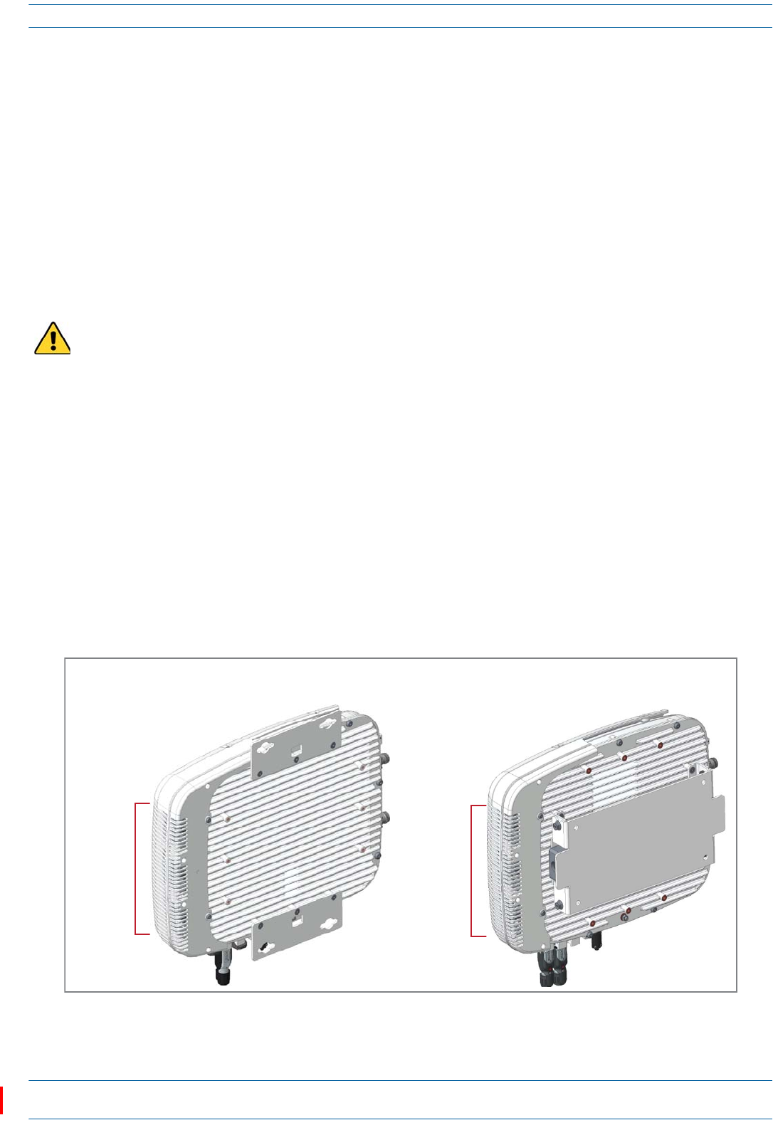
M0201AAC ION®-E Series Low Power Carrier Access Point Installation Guide
© February 2018 CommScope, Inc. Page 49
CAP L Maintenance
CAP L MAINTENANCE
ThefollowingsectionstellyouhowtoremoveaCAPLfrommountingbrackets,andprovidespreventative
maintenanceinstructions.
Remove a CAP L from a Wall or Ceiling Mount
ShouldyouneedtoremovetheCAPLfromawallorceilingmount,dothefollowing.
1ForCAPLswithaCopperInterfaceonly;ifremovingaCAPLwithaFiberInterface,skiptoStep2.
aPresstheCAPLPowerpushbuttontoplacetheCAPLintoalow-powersleepstate,whichallowsyou
tosafelyunplugtheCAPLwithoutapowerarc.
bMakesurethebluePowerLEDisoff.
2UnplugtheCAPLcables.
3Ifagroundwireisinstalled,loosenthegroundingscrewandremovethegroundwire.
4ReversetheinstallationstepsthatcorrespondtohowthisCAPLismounted.
Preventative CAP L Maintenance for CAP Ls with the Fan Kit Option
TheCAPLdoesnotrequireextensivepreventativemaintenancemeasures.However,checkingthe
cleanlinessofaCAPLthathastheFanKitoptionatregularly-scheduledintervalsisrecommended,
particularlytheenclosurevents,whichhelpsmaintainthelongevityofthefansandheatsinks.Figure21
showstwodifferentCAPLconfigurationstohelpyoufindtheenclosurevents.
Figure 21. Examples of CAP L Fan Vent Locations
If you are removing a CAP L with a Copper Interface, you must always press the Power button to power
off the CAP L prior to disconnecting its Power cable.
Enclosure
vents
Boom of CAP L with
240W AC/DC Power Supply Kit
Boom of CAP L with
Flat Mounng Bracket
Enclosure
vents
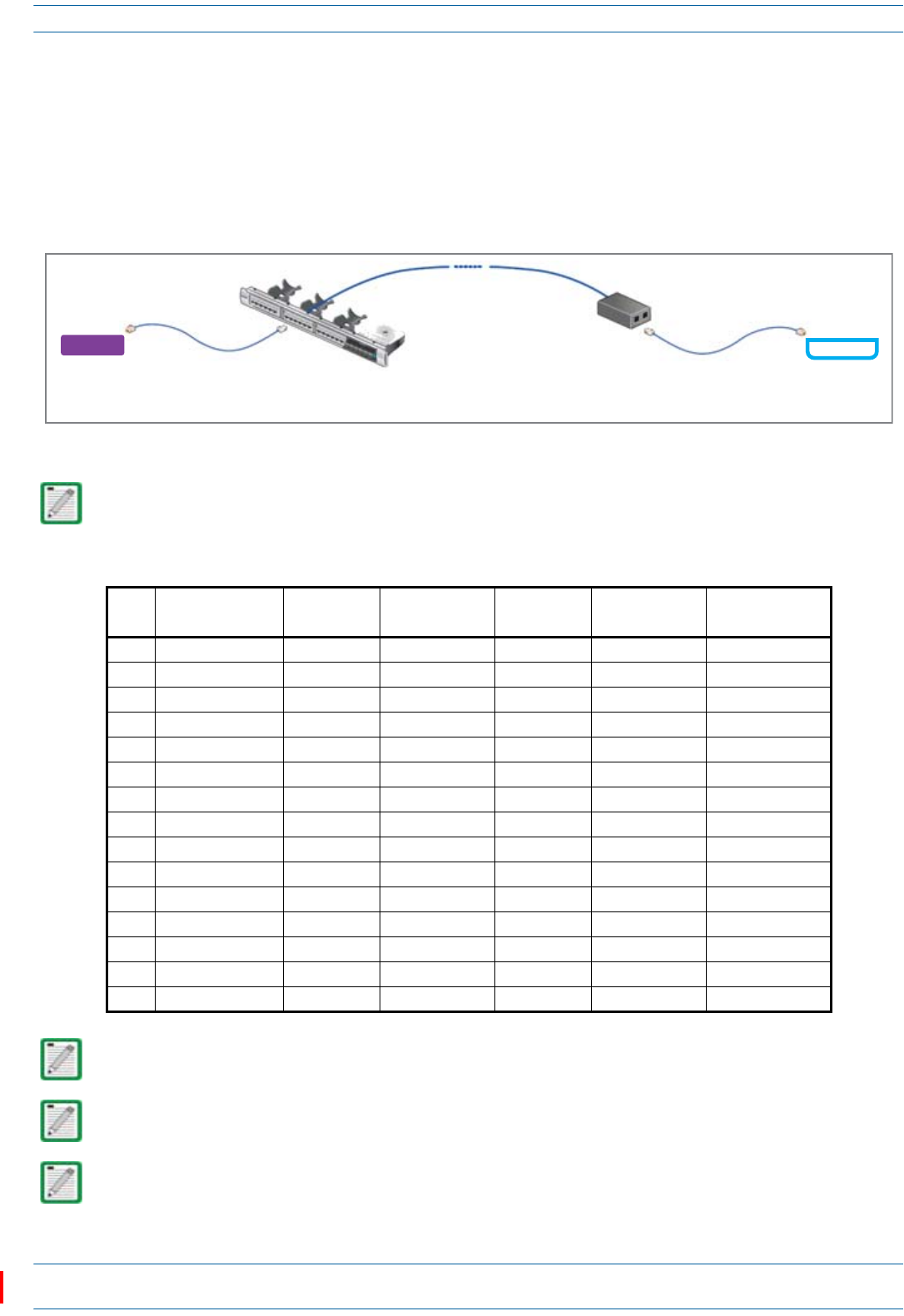
ION®-E Series Low Power Carrier Access Point Installation Guide M0201AAC
Page 50 © February 2018 CommScope, Inc.
Cat6A Specifications and Testing Requirements
CAT6A SPECIFICATIONS AND TESTING REQUIREMENTS
Cat6Aconnectionsmustbetestedwithadevicethatcanmeasurethecableparametersagainstthethresholds
definedinANSI/TIAstandards(suchastheFlukeDTX-1800andDSX-5000).Figure22showstheend-to-end
channelfromtheCAN/TENtotheCAPL,whichisinclusiveoftheCat6Acable,theCat6APatchCord,andthe
Panelandconnectionbox.Theend-to-endchannelmustmeettheCat6AU/UTPperformancedefinedbythe
TIA/EIA568C.2standard;seeTable9onpage50.
Figure 22. ION-E End-to-End Channel
Some cables list their performance in “typical” performance values. However, sweep-testing is necessary
to confirm actual performance. CommScope strongly recommends using Cat6A cable that has been tested
to the listed frequency with test confirmation available for inspection.
Table 9. Cat6A U/UTP Performance Standards (TIA/EIA 568 C.2)
MHz Insertion Loss (dB)
Channel/Link
NEXT (dB)
Channel/Link
PSum NEXT (dB)
Channel/Link
ACRF (dB)
Channel/Link
PSum ACRF (dB)
Channel/Link
Return Loss
(dB) Channel/Link
1 2.3/1.9 65.0/65.0 62.0/62.0 63.3/64.2 60.3/61.2 19.0/19.1
4 4.2/3.5 63.0/64.1 60.5/61.8 51.2/52.1 48.2/49.1 19.0/21.0
8 5.8/5.0 58.2/59.4 55.6/57.0 45.2/46.1 42.2/43.1 19.0/21.0
10 6.5/5.5 56.6/57.8 54.0/55.5 43.3/44.2 40.3/41.2 19.0/21.0
16 8.2/7.0 53.2/54.6 50.6/52.2 39.2/40.1 36.2/37.1 18.0/20.0
20 9.2/7.8 51.6/53.1 49.0/50.7 37.2/38.2 34.2/35.2 17.5/19.5
25 10.2/8.8 50.0/51.5 47.3/49.1 35.3/36.2 32.3/33.2 17.0/19.0
31.25 11.5/9.8 48.4/50.0 45.7/47.5 33.4/34.3 30.4/31.3 16.5/18.5
62.5 16.4/14.1 43.4/45.1 40.6/42.7 27.3/28.3 24.3/25.3 14.0/16.0
100 20.9/18.0 39.9/41.8 37.1/39.3 23.3/24.2 20.3/21.2 12.0/14.0
200 30.1/26.1 34.8/36.9 31.9/34.3 17.2/18.2 14.2/15.2 9.0/11.0
250 33.9/29.5 33.1/35.3 30.2/32.7 15.3/16.2 12.3/13.2 8.0/10.0
300 37.4/32.7 31.7/34.0 28.8/31.4 13.7/14.6 10.7/11.6 7.2/9.2
400 43.7/38.5 28.7/29.9 25.8/27.1 11.2/12.1 8.2/9.1 6.0/8.0
500 49.3/43.8 26.1/26.7 23.2/23.8 9.3/10.2 6.3/7.2 6.0/8.0
Propagation Delay is 555 nanoseconds for channel/498 nanoseconds for link tested at 10 MHz.
Delay Skew is 50 nanoseconds for channel/44 nanoseconds for link tested at 10 MHz.
For additional information, see also CommScope Product Specifications for the GigaSPEED X10D® 2091B
ETL Verified Category 6A U/UTP Cable (760107201 | 2091B BL 4/23 W1000). (Click here access the
document online.)
Cat6A
Patch
Cord
Cat6A Cable
Modular
Panel
Connecon
Box
CAT/TEN CAP L
Cat6A
Patch
Cord

M0201AAC ION®-E Series Low Power Carrier Access Point Installation Guide
© February 2018 CommScope, Inc. Page 51
Contacting CommScope
CONTACTING COMMSCOPE
ThefollowingsectionstellyouhowtocontactCommScopeforadditionalinformationorforassistance.
DCCS Global Technical Support
ThefollowingsectionstellyouhowtocontacttheCommScopeDistributedCoverageandCapacitySolutions
(DCCS)TechnicalSupportteam.Supportisavailable7daysaweek,24hoursaday.
Telephone Helplines
UsethefollowingHelplinetelephonenumberstogetlivesupport,24hoursaday:
Online Support
TogototheCommScopeDCCSSupportRequestwebsitefromwhichyoucaninitiateaTechnicalSupport
ticket,dooneofthefollowing:
•ScantheQRCodetotheright.
•IfviewingthisdocumentonlineasaPDF,clickonthefollowingURLlink:
http://www.commscope.com/wisupport
•EntertheprecedingURLintoyourwebbrowser,andthenpressENTERonyourkeyboard.
Waste Electrical and Electronic Equipment Recycling
CountryspecificinformationaboutcollectionandrecyclingarrangementspertheWasteElectricaland
ElectronicEquipment(WEEE)DirectiveandimplementingregulationsisavailableonCommScope’swebsite.
ToaccessinformationontheCommScoperecyclingprogram,doanyofthefollowing:
•ScantheQRCodetotheright.
•IfviewingthisdocumentonlineasaPDF,clickonthefollowingURLlink:
http://www.commscope.com/About-Us/Corporate-Responsibility-and-Sustainability/Environment/Rec
ycling/
•EntertheprecedingURLintoyourwebbrowser,andthenpressENTERonyourkeyboard.
24x7 +1888-297-6433(TollfreeforU.S.andCanada)
EMEA 8:00-17:00 (UTC +1) +80073732837(TollfreeforpartsofEMEAandAustralia)
+49909969333(Tollchargeincurred)
CallstoanEMEAHelplineoutsideofthe8:00to17:00timeframewillbe
forwardedtothe24x7Helpline.

ION®-E Series Low Power Carrier Access Point Installation Guide M0201AAC
Page 52 © February 2018 CommScope, Inc.
Contacting CommScope
Hardware to Software Mapping Information
1ScantheQRCodetotherighttoviewordownloadtheminimumsoftwarerequirementsfor
eachoftheDCCShardwaremodules.Alternatively,youcangotothefollowingwebaddressto
accesstheportal:
http://www.commscope.com/collateral/DCCS_HW_SW_Mapping/
2Clickonadocumentlinktoopenit,orrightclickonthelinkandselecttheSave target as…optionfromthe
contextualmenu.
DCCS Technical Training
1ToaccesstrainingontheonlineCommScopeDASandSmallCellInstitute,dooneofthefollowing:
•ScantheQRCodetotheright.
•IfviewingthisdocumentonlineasaPDF,clickonthefollowingURLlink.
http://www.commscopetraining.com/courses/dassc/
•EntertheprecedingURLintoyourwebbrowser,andthenpressENTERonyourkeyboard.
2Reviewthecourseslistedinseparatecoursepanels;forfurtherinformationonacourse,clickitsFull
detailsbutton.Instructor-ledcoursesareconductedinNorthAmericaandEurope.Beforechoosinga
course,pleaseverifytheregion.
3Toviewthecoursescheduleandregister,clickCourse Registrationatthetopofthecoursepage;this
opensthePartner Learning Center Loginpage.
•Ifyouhaveanaccount,enteryourUsernameandPassword,andthenclickLogin.(ClickontheReset
Passwordlinkifyoudonothaveyourlogininformation.)
•Ifyoudon'thaveanaccount,clickontheCreate New User AccountlinkundertheLoginbutton,and
followtheprompts.
Onceyouhaveloggedin,youwillseealistofavailableclassdates.
4ClickthedateyoupreferandselecttheEnrollorRegisterNowbuttontoenroll.Followtheprompts
throughthepaymentprocess.
5ClickeithertheAvailable TrainingorCalendartabtoviewothertrainingcourses.
Fortrainingrelatedquestions,pleasecontacttheCommScopeDASandSmallCellInstituteatoneofthe
followingemails,asappropriateforyourlocation:
Americas: DASTrainingUS@CommScope.com
EMEA: DASTrainingEMEA@CommScope.com

M0201AAC ION®-E Series Low Power Carrier Access Point Installation Guide
© February 2018 CommScope, Inc. Page 53
Contacting CommScope
Accessing ION-E Series User Documentation
1ScantheQRCodetotherighttogodirectlytotheCommScopeDCCSCustomerPortal,where
youcanaccesstheDCCSuserdocumentation.
Alternatively,youcangotothefollowingwebaddresstoaccesstheportal:
https://www.mycommscope.com
2AccesstotheCustomerPortalrequiresauseraccountandpassword.OntheSignInpage,dooneofthe
following:
•Ifyouhaveanaccount,enteryourEmailaddressandPassword,andthenclickSignIn.
•Ifyoudon’thaveanaccount,clickNewuserregistration,andfollowtheprompts.
3ClickDCCStoopenthesite.
4Selectyoursite,andthenclickonaproductlinktoopentheproductpage.
5Clickonthetitleofanydocumenttoopenit.