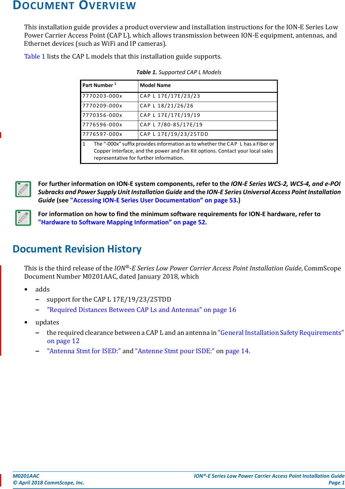
Andrew Wireless System CAPL17E192325 ION-E Remote Unit for cellular systems User Manual
Andrew Wireless System ION-E Remote Unit for cellular systems
UserManual.wiki
>
Andrew Wireless System
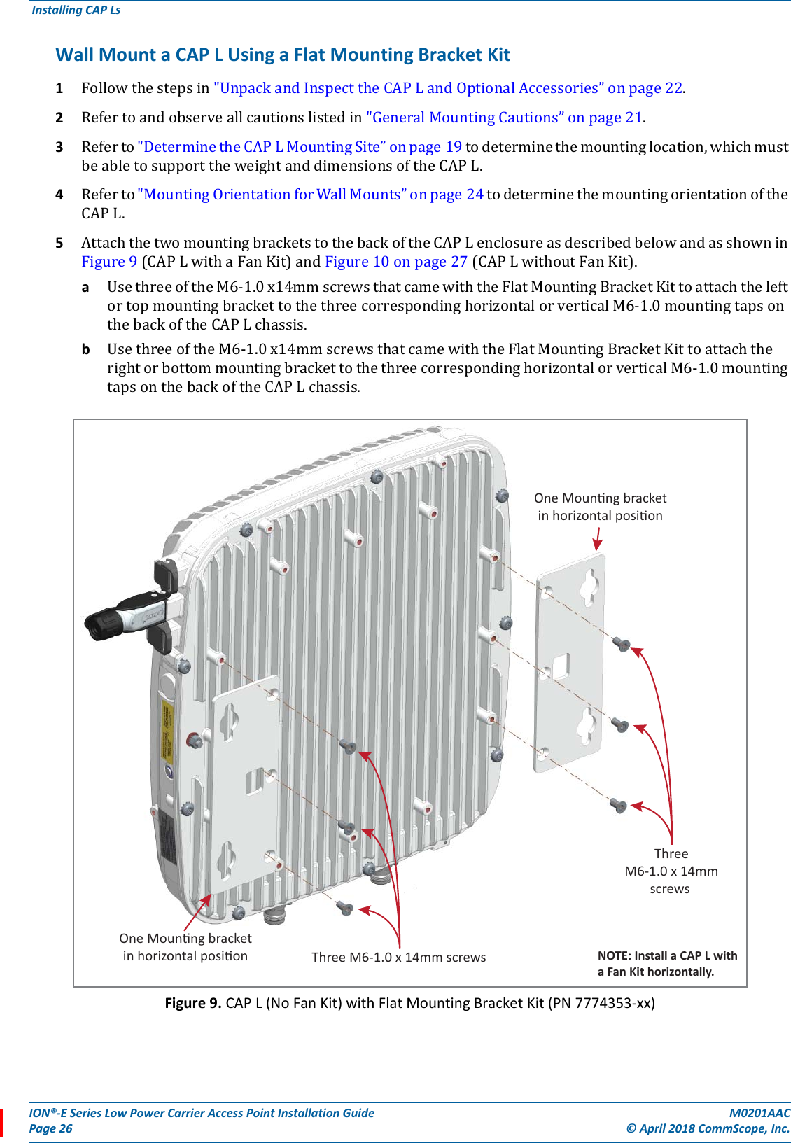
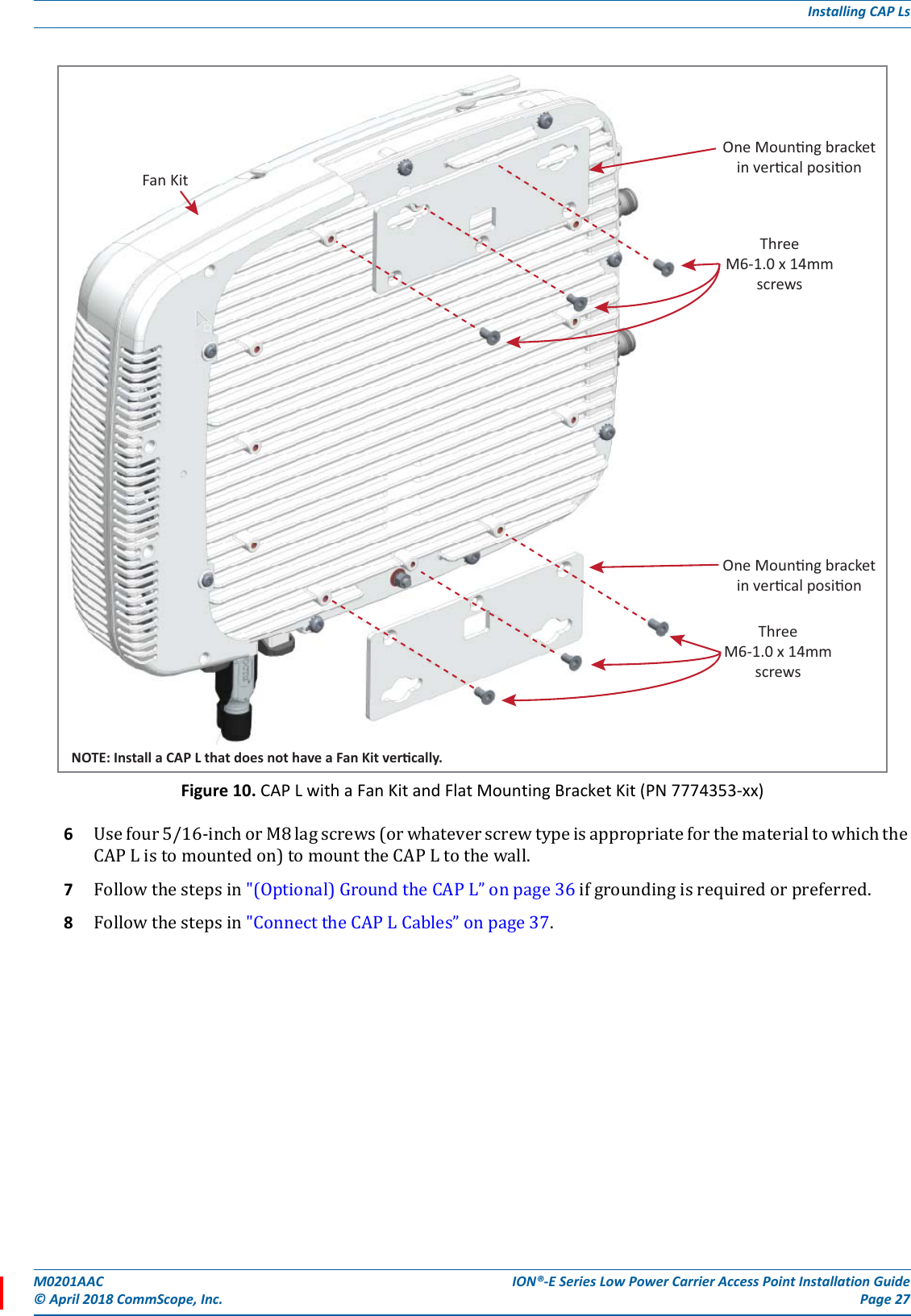
>
CAPL17E192325 User Manual
user manual
Navigation menu
Upload a User Manual
Namespaces
Wiki Guide
HTML
PDF
Info
Views
User Manual
Discussion / Help
Navigation
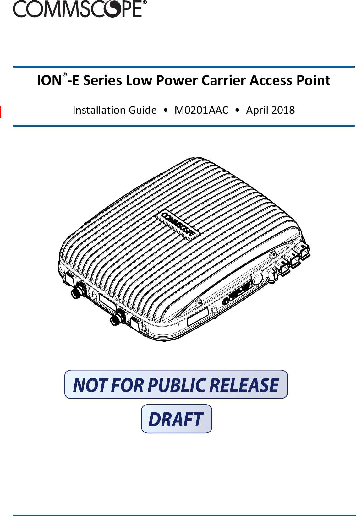
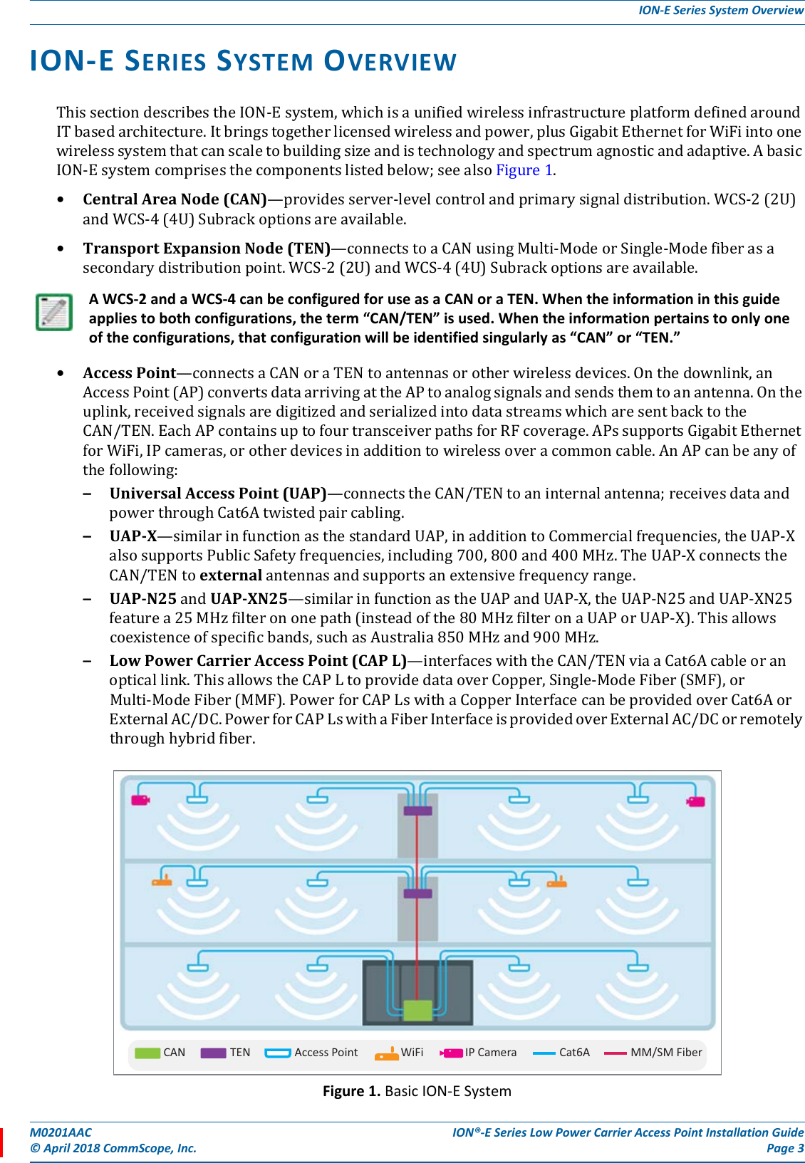
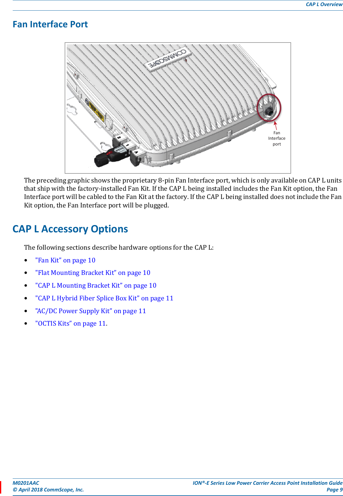
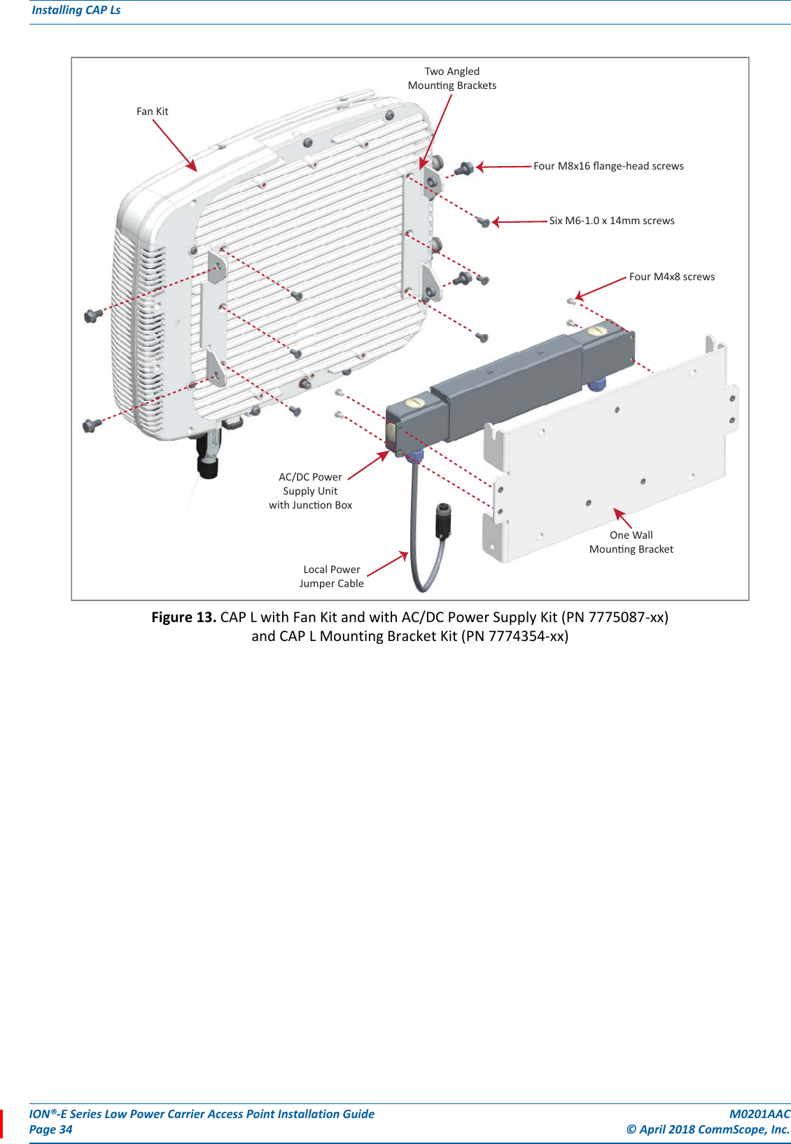
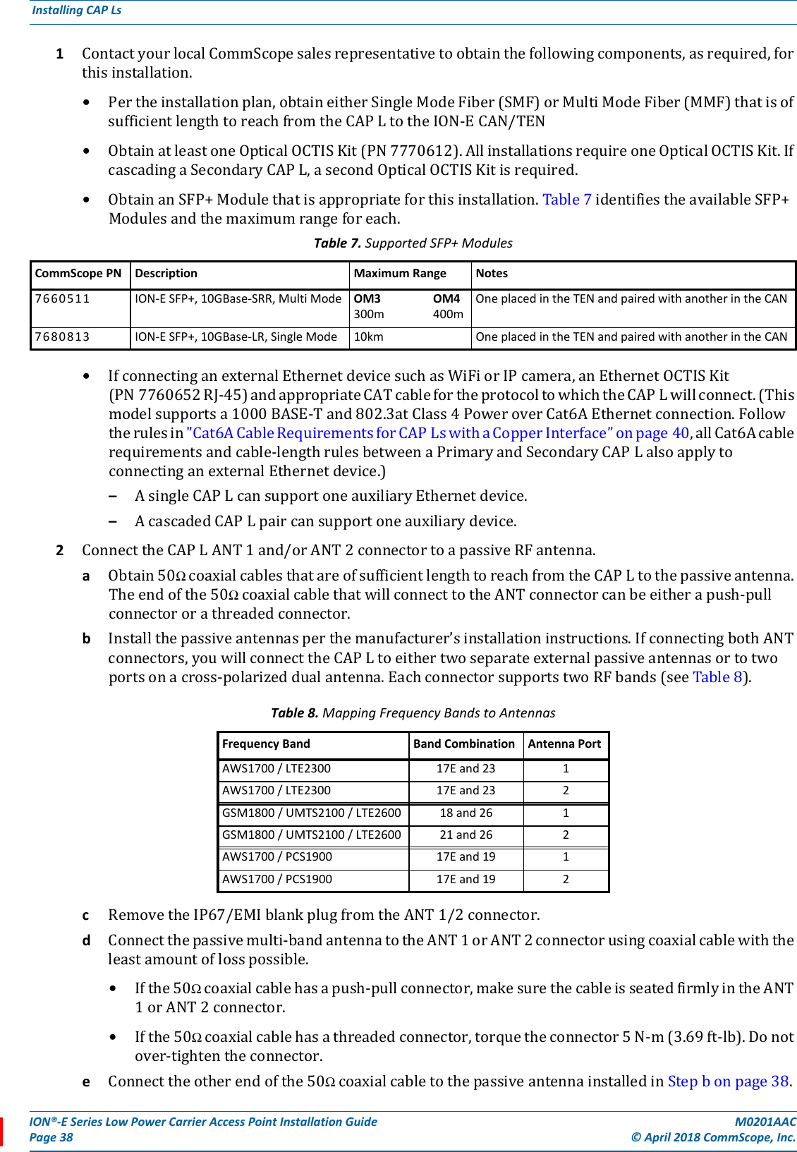
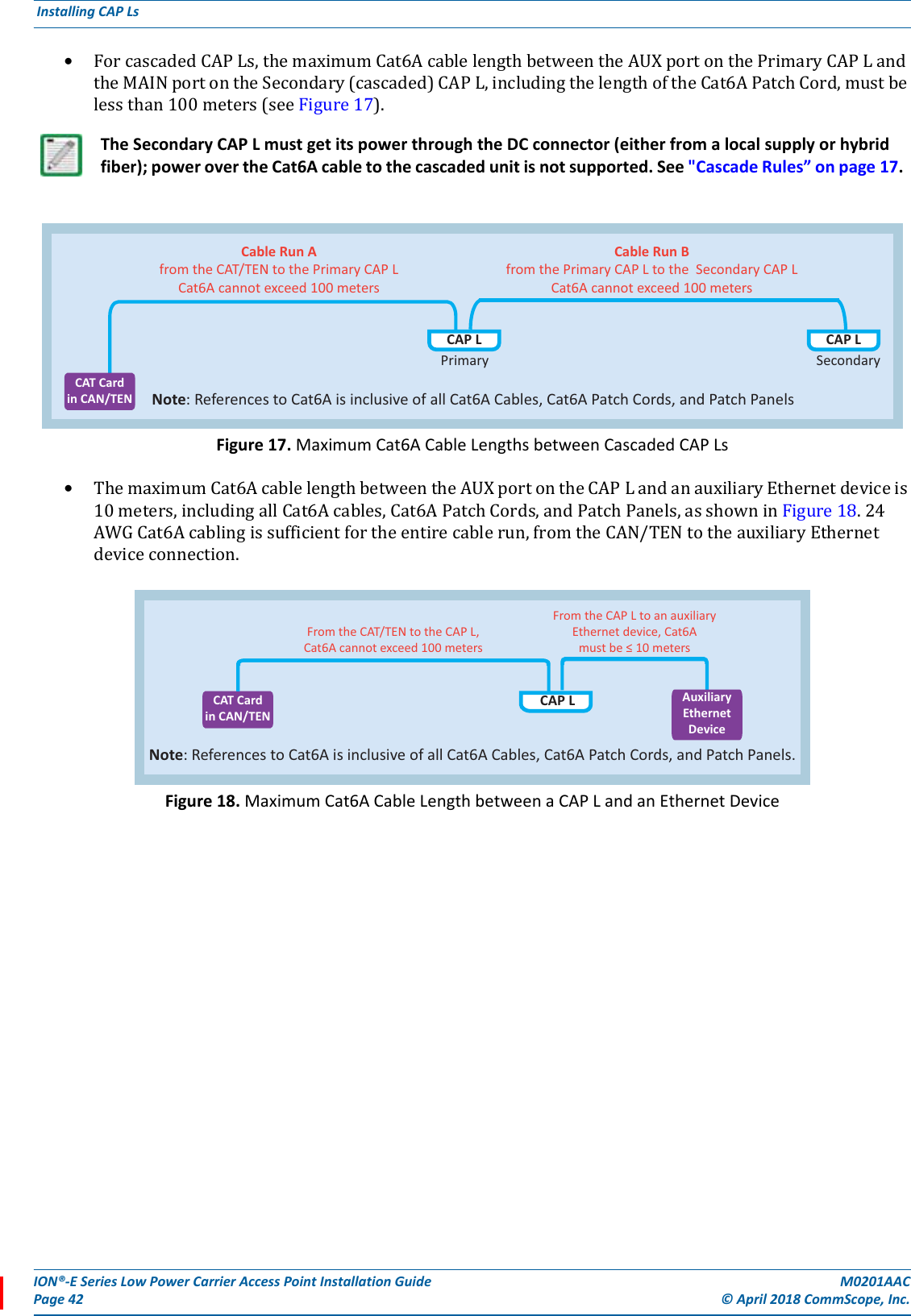
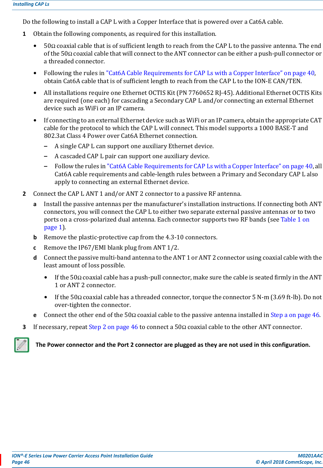
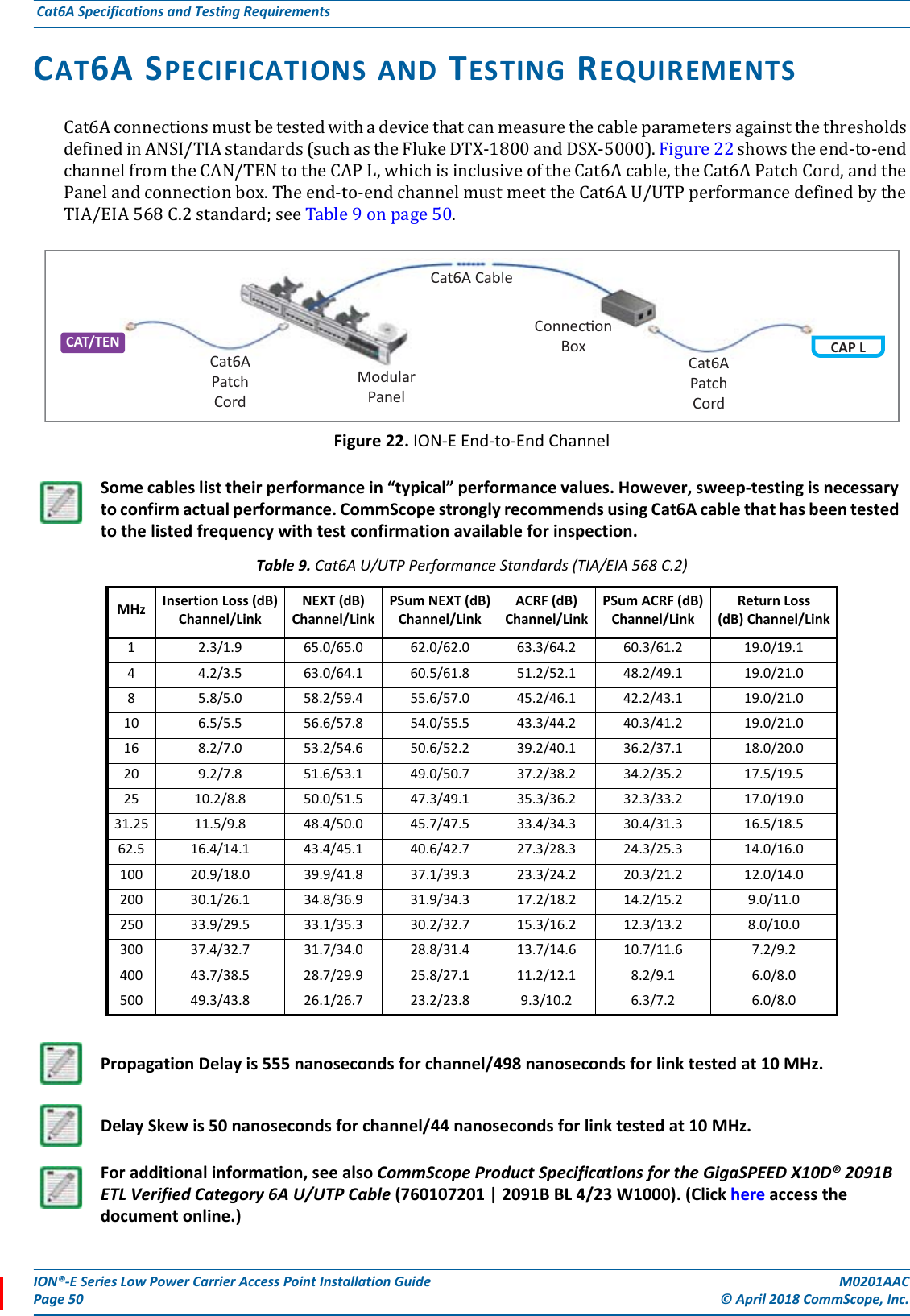
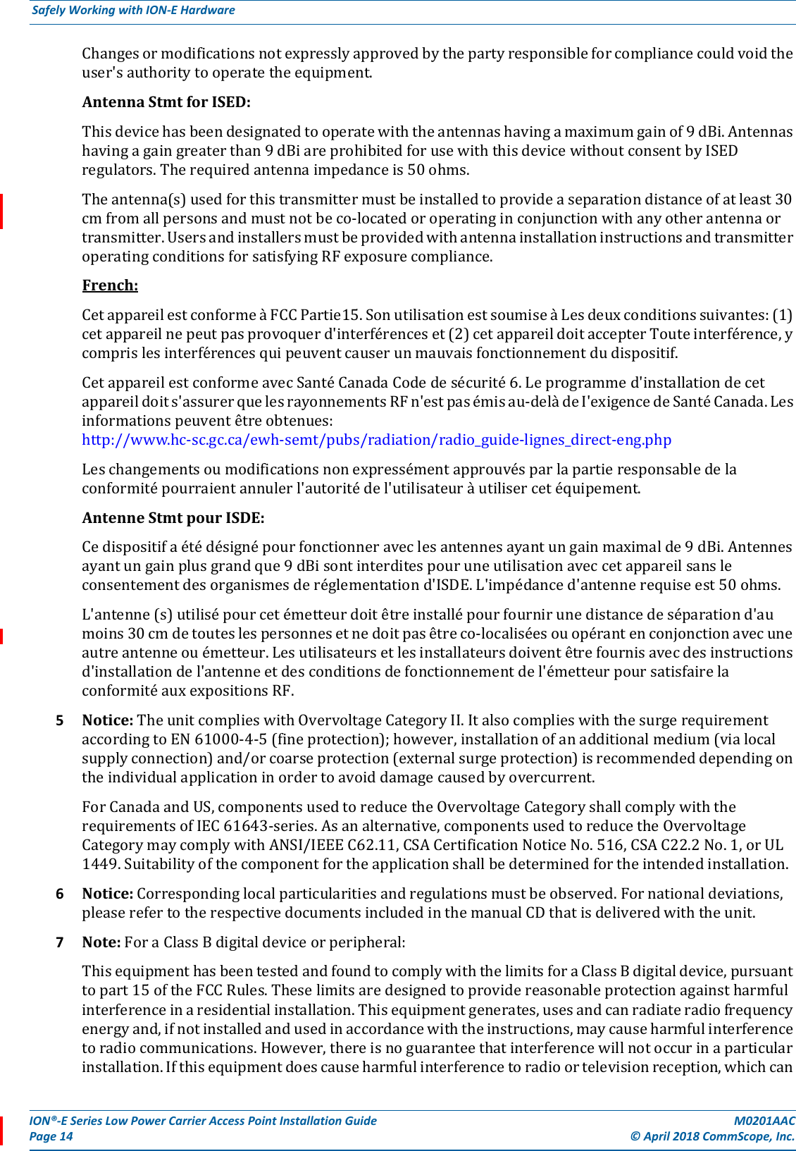
![M0201AAC ION®-E Series Low Power Carrier Access Point Installation Guide© April 2018 CommScope, Inc. Page 13Safely Working with ION-E HardwareGuard Against Damage from Electro-Static DischargeCompliance1Notice:Forinstallations,whichhavetocomplywithFCCRFexposurerequirements,theantennaselectionandinstallationmustbecompletedinawaytoensurecompliancewiththoseFCCrequirements.DependingontheRFfrequency,ratedoutputpower,antennagain,andthelossbetweentherepeaterandantenna,theminimumdistanceDtobemaintainedbetweentheantennalocationandhumanbeingsiscalculatedaccordingtothisformula:where•P(mW)istheradiatedpowerattheantenna,i.e.themax.ratedrepeateroutputpowerinadditiontotheantennagainminusthelossbetweentherepeaterandtheantenna.•PD(mW/cm²)istheallowedPowerDensitylimitacc.to47CFR1.1310(B)forgeneralpopulation/uncontrolledexposureswhichis–f(MHz)/1500forfrequenciesfrom300MHzto1500MHz–1forfrequenciesfrom1500MHzto100,000MHzRFexposurecompliancemayneedtobeaddressedatthetimeoflicensing,asrequiredbytheresponsibleFCCBureau(s),includingantennaco-locationrequirementsof1.1307(b)(3).2Notice:ForinstallationswhichhavetocomplywithEuropeanEN50385exposurecompliancerequirements,thefollowingPowerDensitylimits/guidelines(mW/cm²)accordingtoICNIRParevalid:•0.2forfrequenciesfrom10MHzto400MHz•F(MHz)/2000forfrequenciesfrom400MHzto2GHz•1forfrequenciesfrom2GHzto300GHz3Notice:Installationofthisequipmentisinfullresponsibilityoftheinstaller,whohasalsotheresponsibility,thatcablesandcouplersarecalculatedintothemaximumgainoftheantennas,sothatthisvalue,whichisfiledintheFCCGrantandcanberequestedfromtheFCCdatabase,isnotexceeded.Theindustrialboostersareshippedonlyasanakedboosterwithoutanyinstallationdevicesorantennasasitneedsforprofessionalinstallation.4Notice:ForinstallationswhichhavetocomplywithFCC/ISEDrequirements:English:ThisdevicecomplieswithFCCPart15.Operationissubjecttothefollowingtwoconditions:(1)thisdevicemaynotcauseinterference,and(2)thisdevicemustacceptanyinterference,includinginterferencethatmaycauseundesiredoperationofthedevice.ThisdevicecomplieswithHealthCanada'sSafetyCode.TheinstallerofthisdeviceshouldensurethatRFradiationisnotemittedinexcessoftheHealthCanada'srequirement.Informationcanbeobtainedathttp://www.hc-sc.gc.ca/ewh-semt/pubs/radiation/radio_guide-lignes_direct-eng.php.Electro-Static Discharge (ESD) can damage electronic components. To prevent ESD damage, always wear an ESD wrist strap when working with ION-E hardware components. Not all ION-E hardware requires grounding. For those ION-E hardware components for which grounding is required, connect the ground wire on the ESD wrist strap to an earth ground source before touching the ION-E component. Wear the wrist strap the entire time that you work with the ION-E hardware.]/[][][24cmmWmWcm PDPD∗∗=π](https://usermanual.wiki/Andrew-Wireless-System/CAPL17E192325/User-Guide-3798386-Page-17.png)
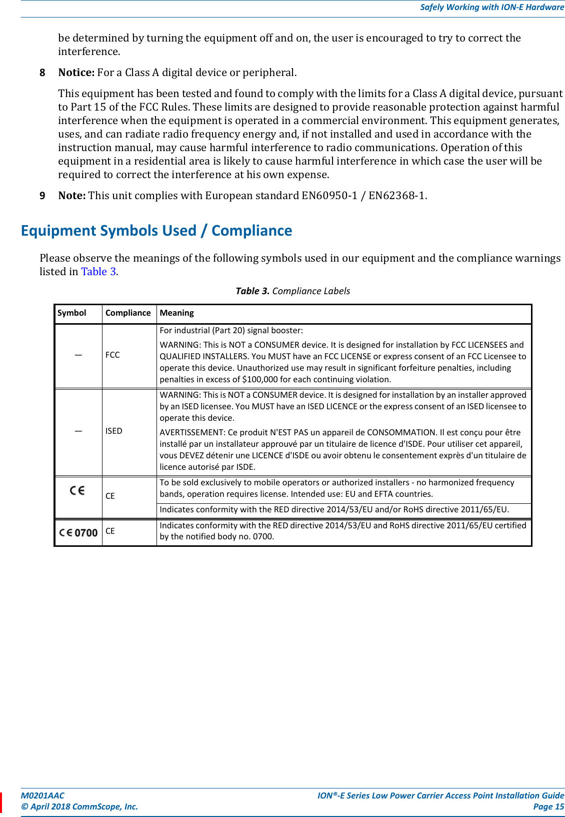
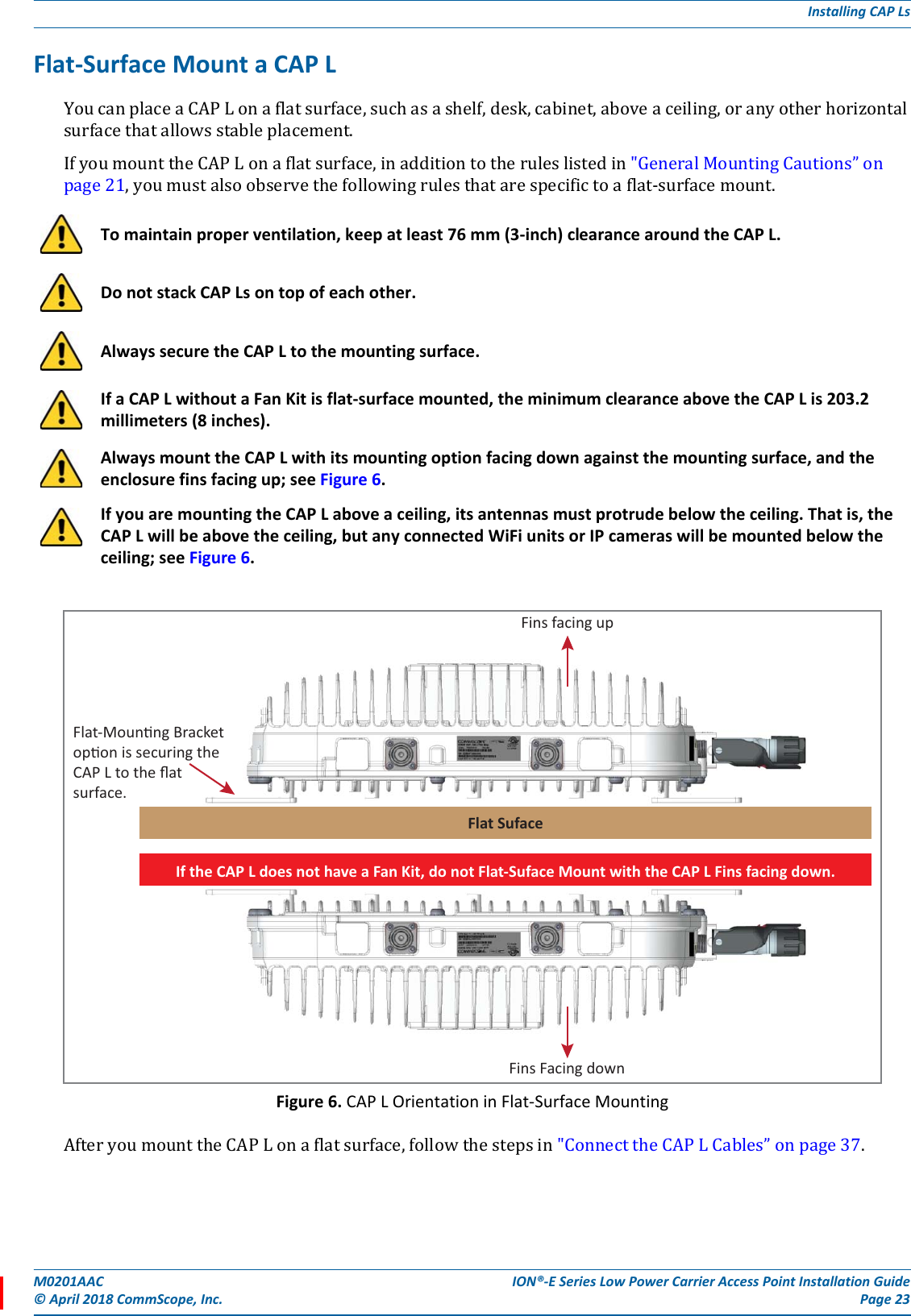
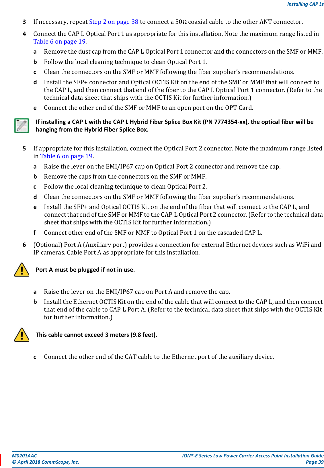
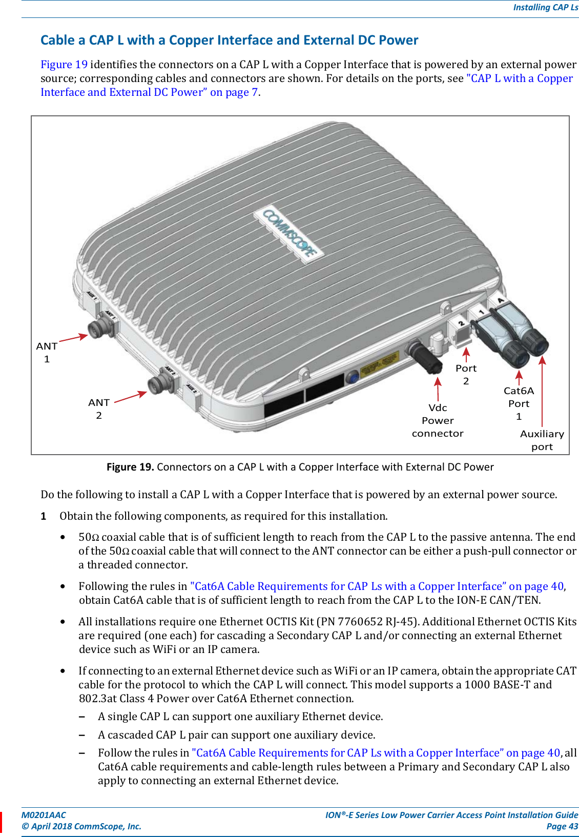
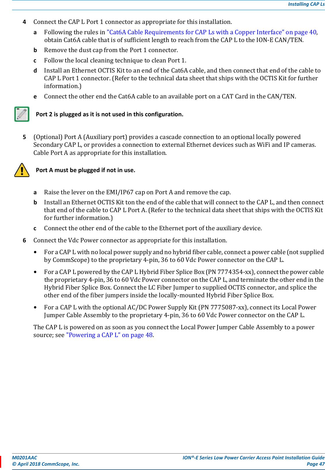
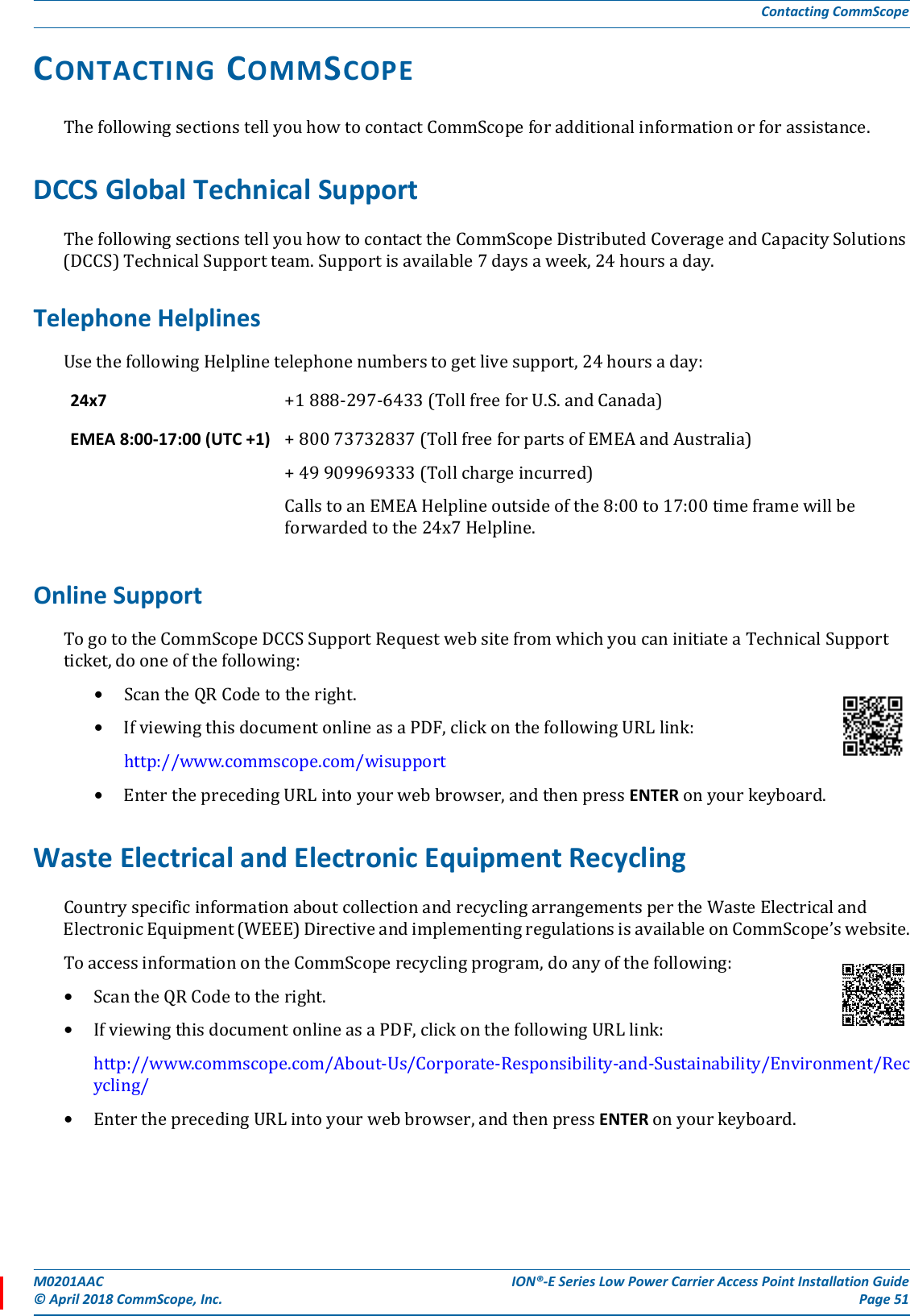
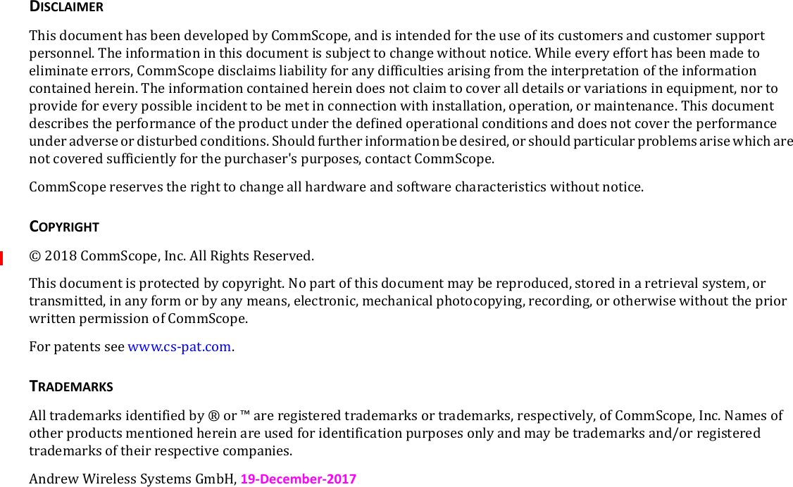
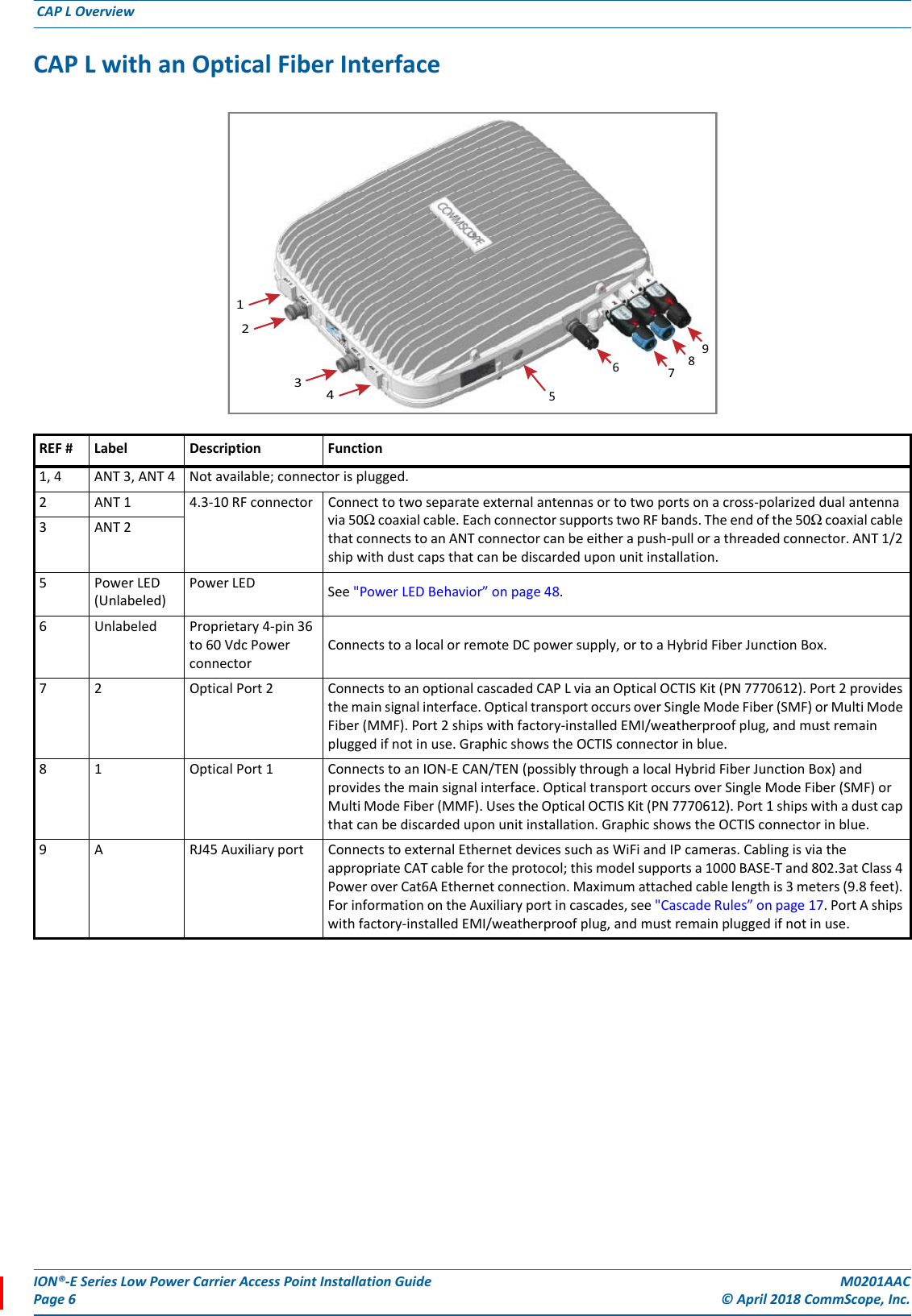
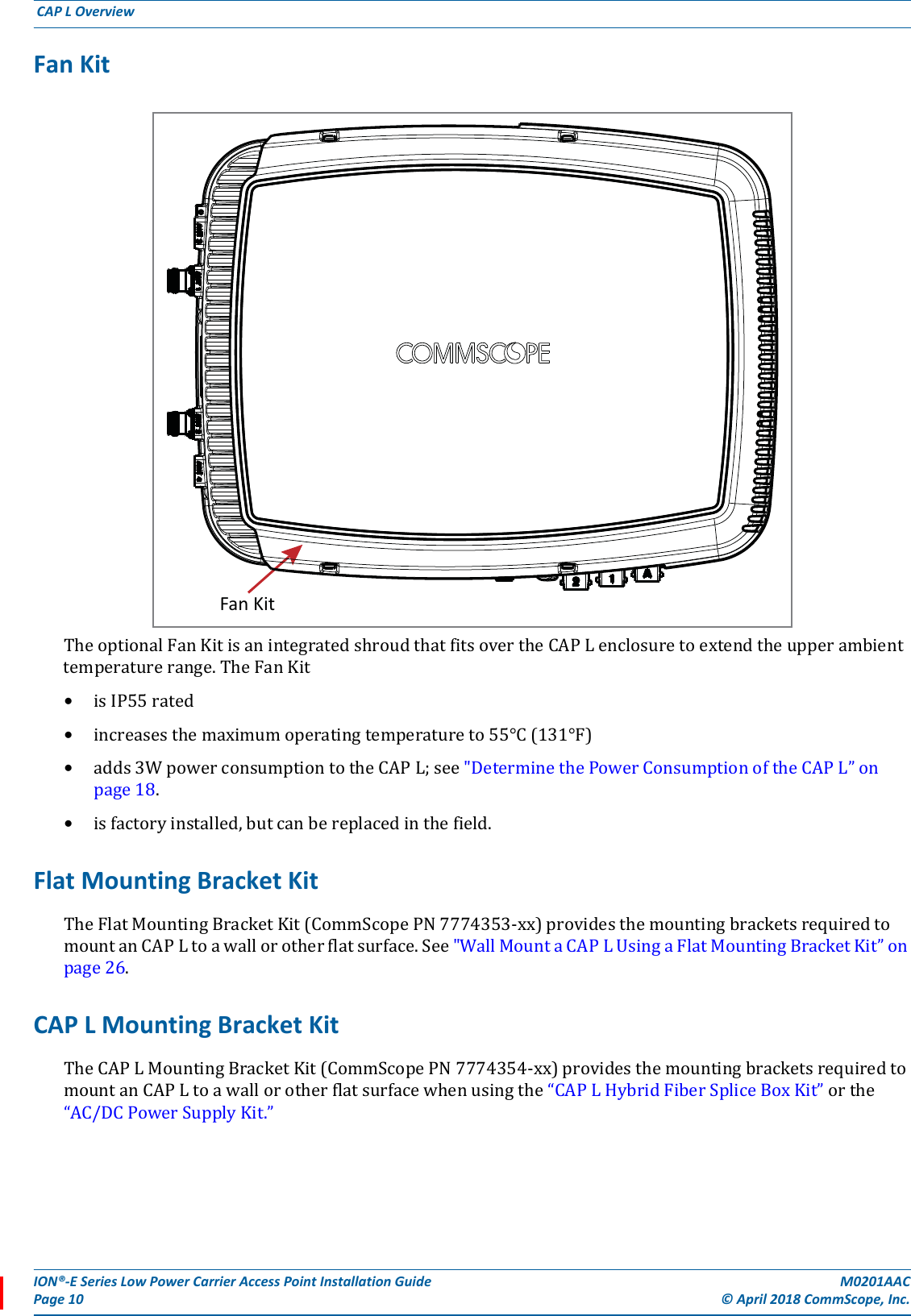
![ION®-E Series Low Power Carrier Access Point Installation Guide M0201AACPage 16 © April 2018 CommScope, Inc. Installing CAP Ls INSTALLING CAP LSThefollowingsectionsguideyouthroughtheinstallationofaCAPL.payattentiontoallcautions,andfollowthestepsintheorderpresented.Prepare for InstallationDothefollowingbeforebeginninginstallation.•Reviewandknowthecautionsin"SafelyWorkingwithION-EHardware”onpage12.•Reviewthesystemdesignplan.•Identifytheequipmentinstallationsite.•Reviewthepowerrequirementstomakesurethesitecansupportthisinstallation.•Mapoutallcableruns.•Identifyandobtainalltoolsandmaterialsrequiredtocompletetheinstallation.Required Distances Between CAP Ls and AntennasTable4liststhedistancethatmustbemaintainedbetweenspecificCAPLmodelsandantennas.Seealsotherequirementslistedin“AntennaStmtforISED:”and“AntenneStmtpourISDE:”onpage14.CAP L Installation RulesWheninstallingaCAPL,youmustobservethefollowingrules.•CAPLwithaCopperInterface–ConnectsviaitsRJ-45porttoaCATCardintheCAN/TEN–EachCATPortcansupporttwoCopperCAPLs,butyoucannotexceedsixCAPLsperCATCard,formaximumtotalsof24CAPLsinastraightcascadeconfiguration,and32CAPLsperWCSSubrackinadaisy-chainconfiguration,butyoumustadheretotheCopperCAPLpoweringrules.–Therecanbeatotalof12CAPLsconnectedtoaCATCardinacascadeconfiguration.TheCAPLconnectedtotheCATCardisthePrimaryCAPL,towhichyoucanconnectoneself-poweredSecondaryCAPL.See"CascadeRules”onpage17.Table 4. Required Antenna DistanceCAP L ModelAntenna gain without cable loss [dBi]Maximum DistanceFCC ISEDMeters Inches Meters InchesCAP L 7 /80-85 / 17 E/19 9 .176 6.9 .256 10.1CAP L 17E/17E/19/19 9 .218 8.58 .259 10.2CAP L 1 7E/17 E /2 3/23 9 .169 6.65 .237 9.33CAP L 1 7E/19 / 23 / 25TDD 9 .178 7.02 .251 9.88](https://usermanual.wiki/Andrew-Wireless-System/CAPL17E192325/User-Guide-3798386-Page-20.png)
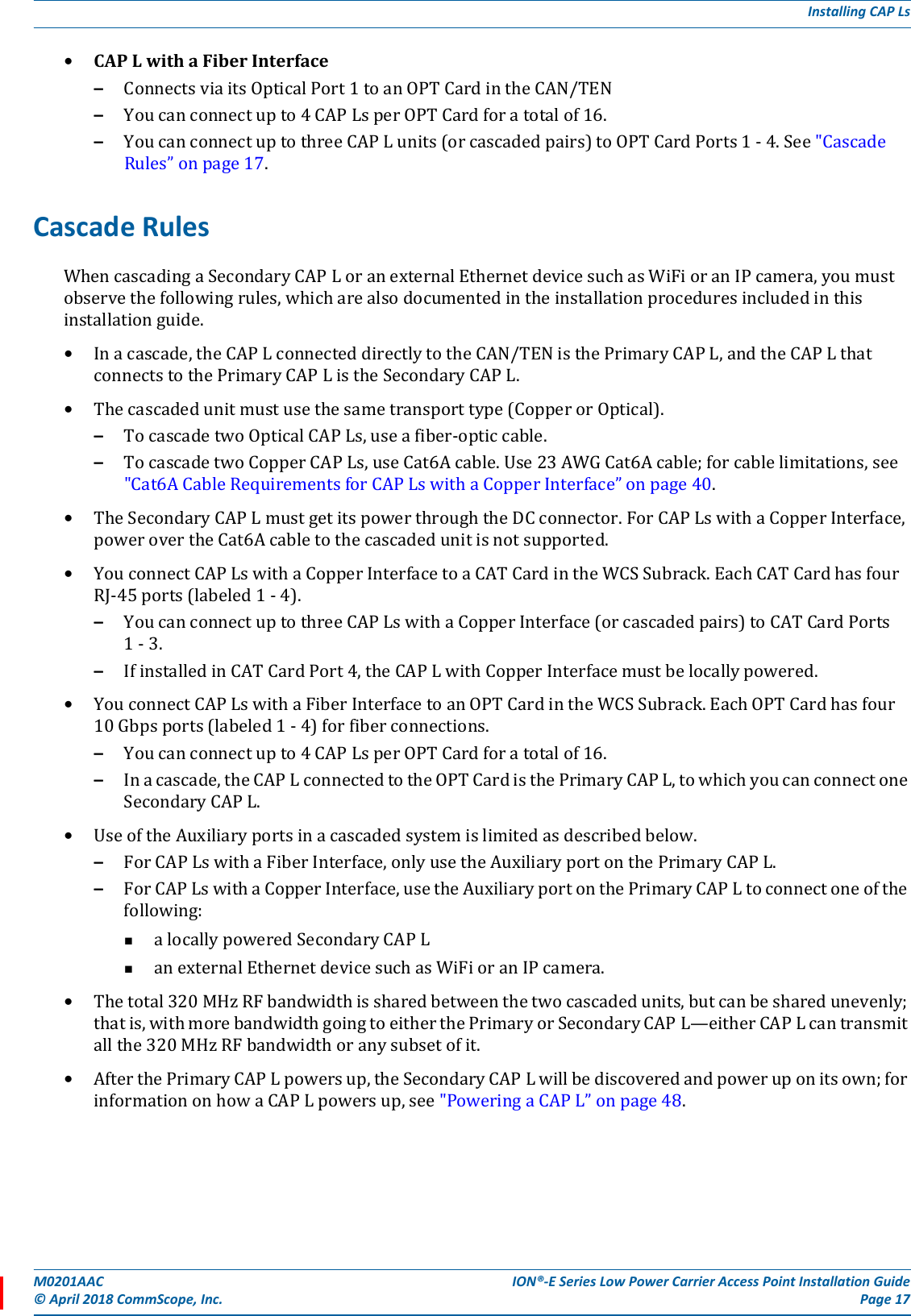
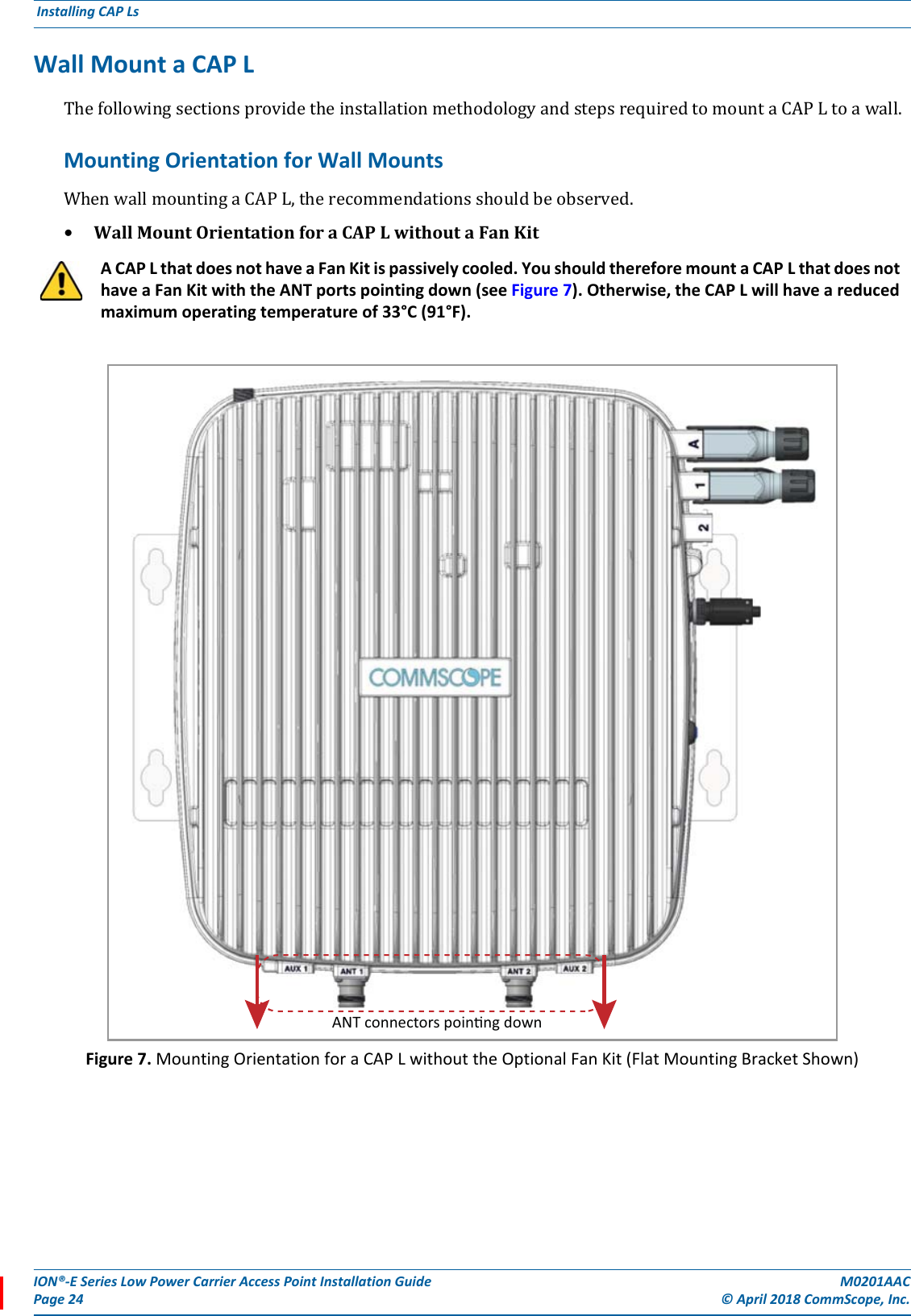
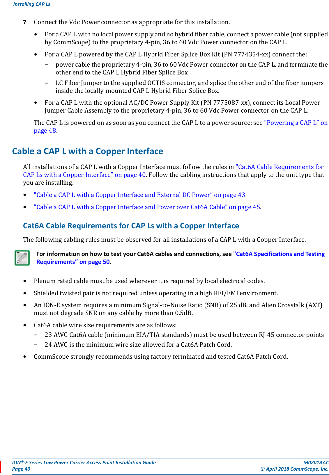
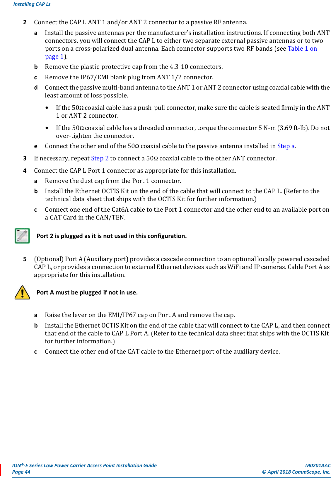
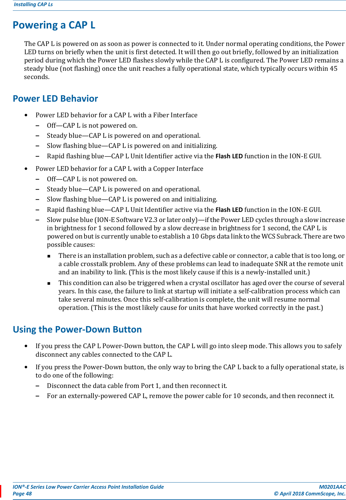
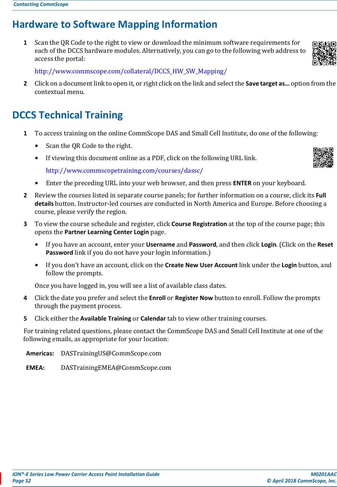
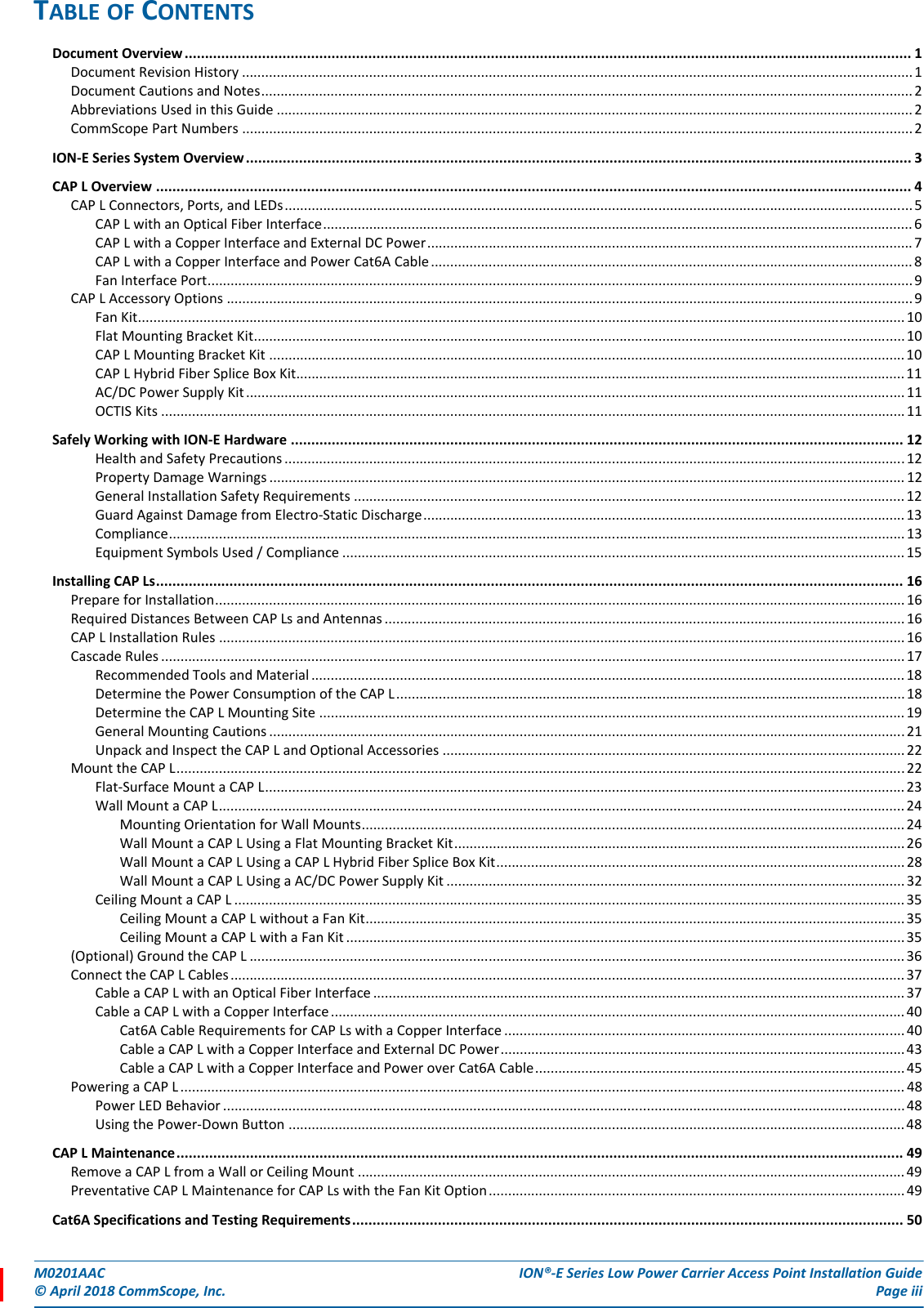
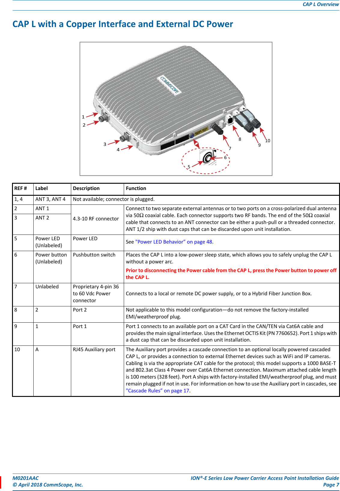
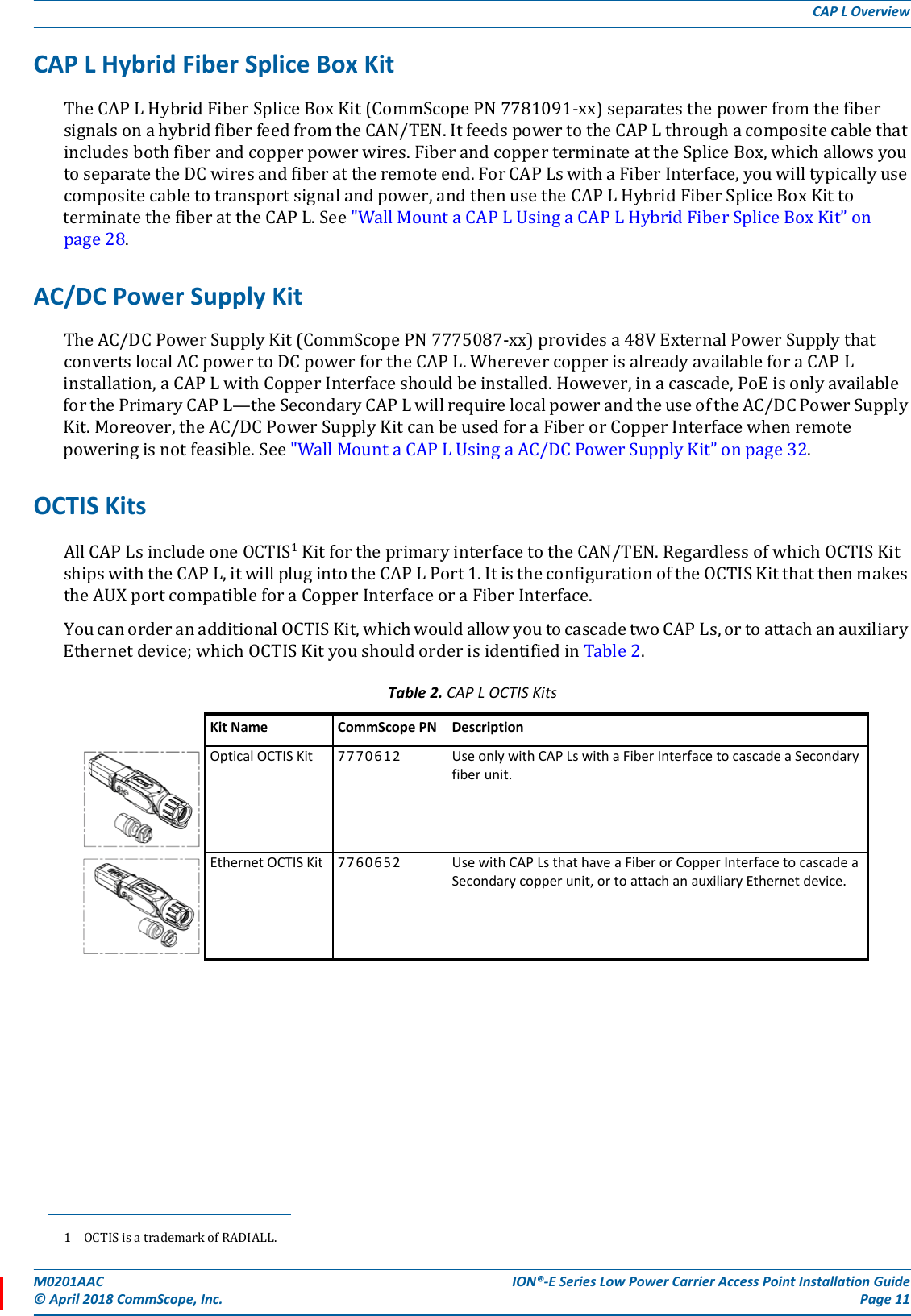
![ION®-E Series Low Power Carrier Access Point Installation Guide M0201AACPage 20 © April 2018 CommScope, Inc. Installing CAP Ls Figure 3. Mounting Dimensions for a CAP L with the Flat Mounting Bracket KitFigure 4. Mounting Dimensions for a CAP L Mounted with the CAP L Hybrid Fiber Splice Box Kit489.12mm[19.26”]512mm[20.16”]144mm[5.67”]440mm[17.32”]406.4mm[16”]120mm[4.72"]383.34mm[15.09"]512mm[20.16”]30mm 2X[1.18"]424.53mm[16.71"]390.33mm[15.37"]24mm[0.94"]2X188mm[7.4"] 460.75mm[18.14"]](https://usermanual.wiki/Andrew-Wireless-System/CAPL17E192325/User-Guide-3798386-Page-24.png)
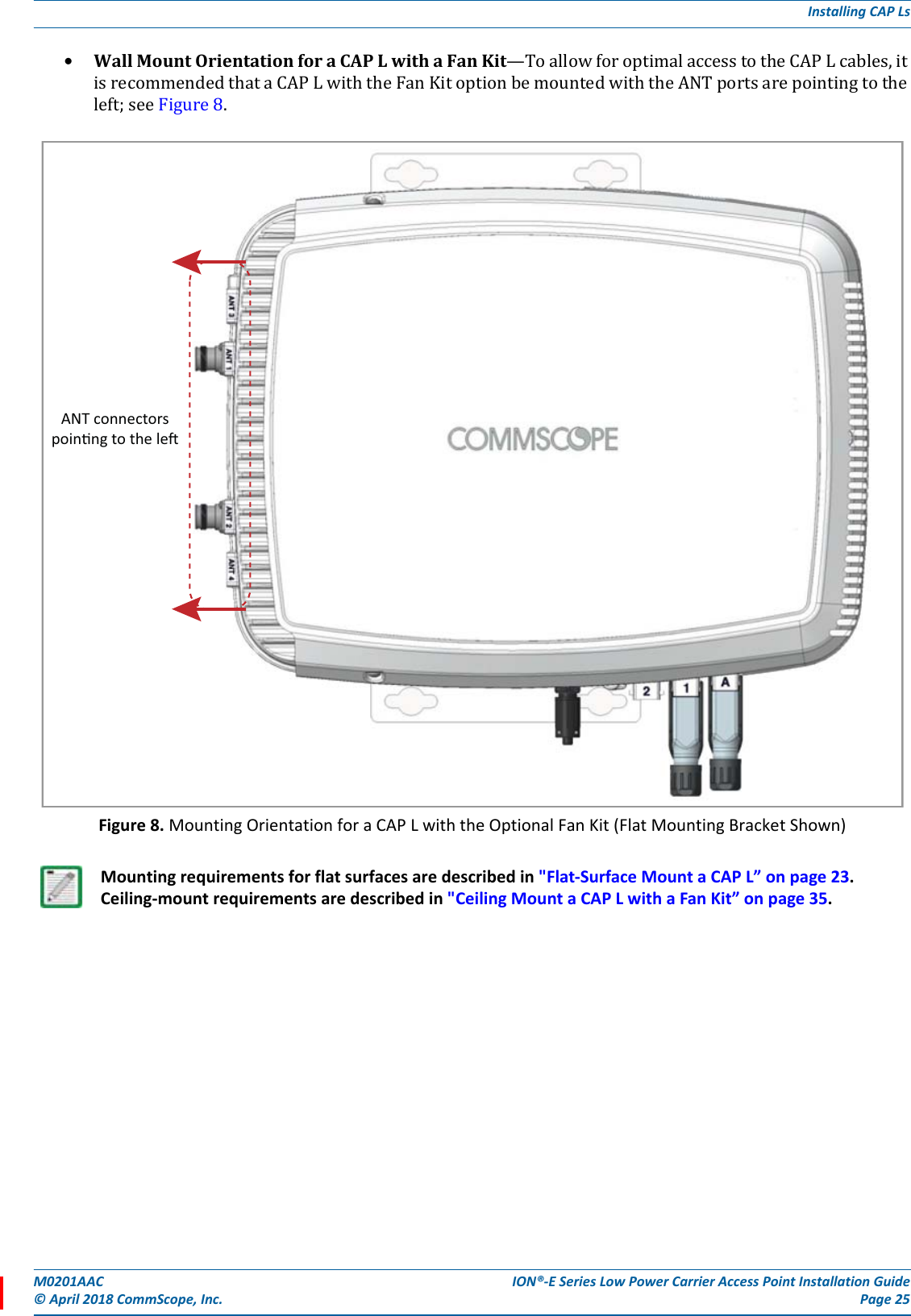
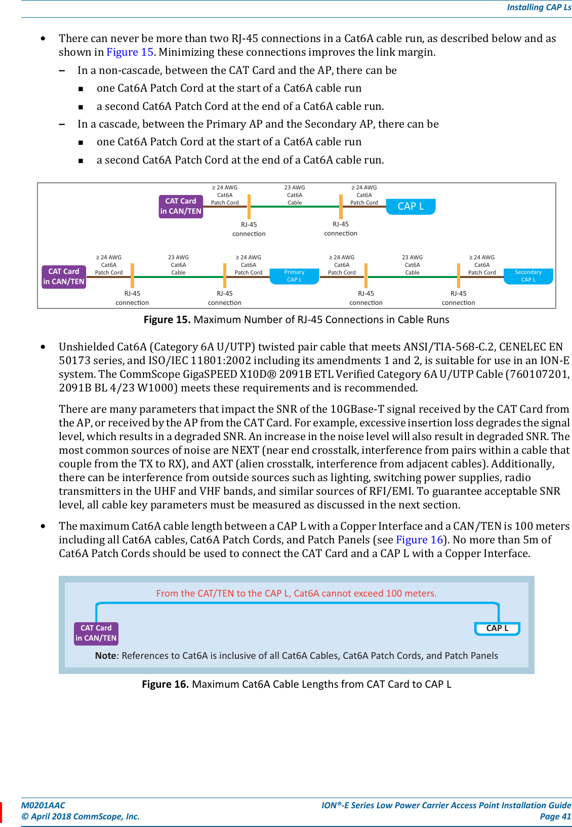
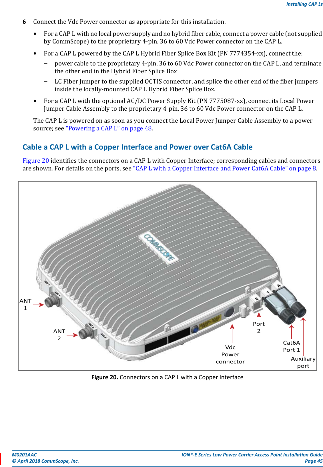
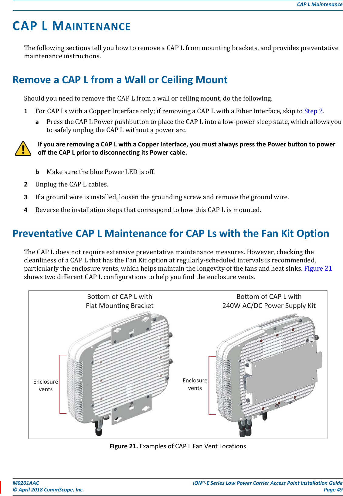
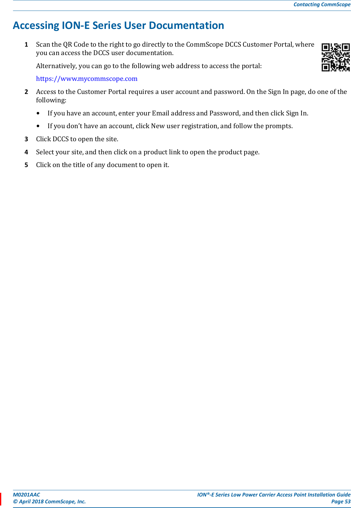
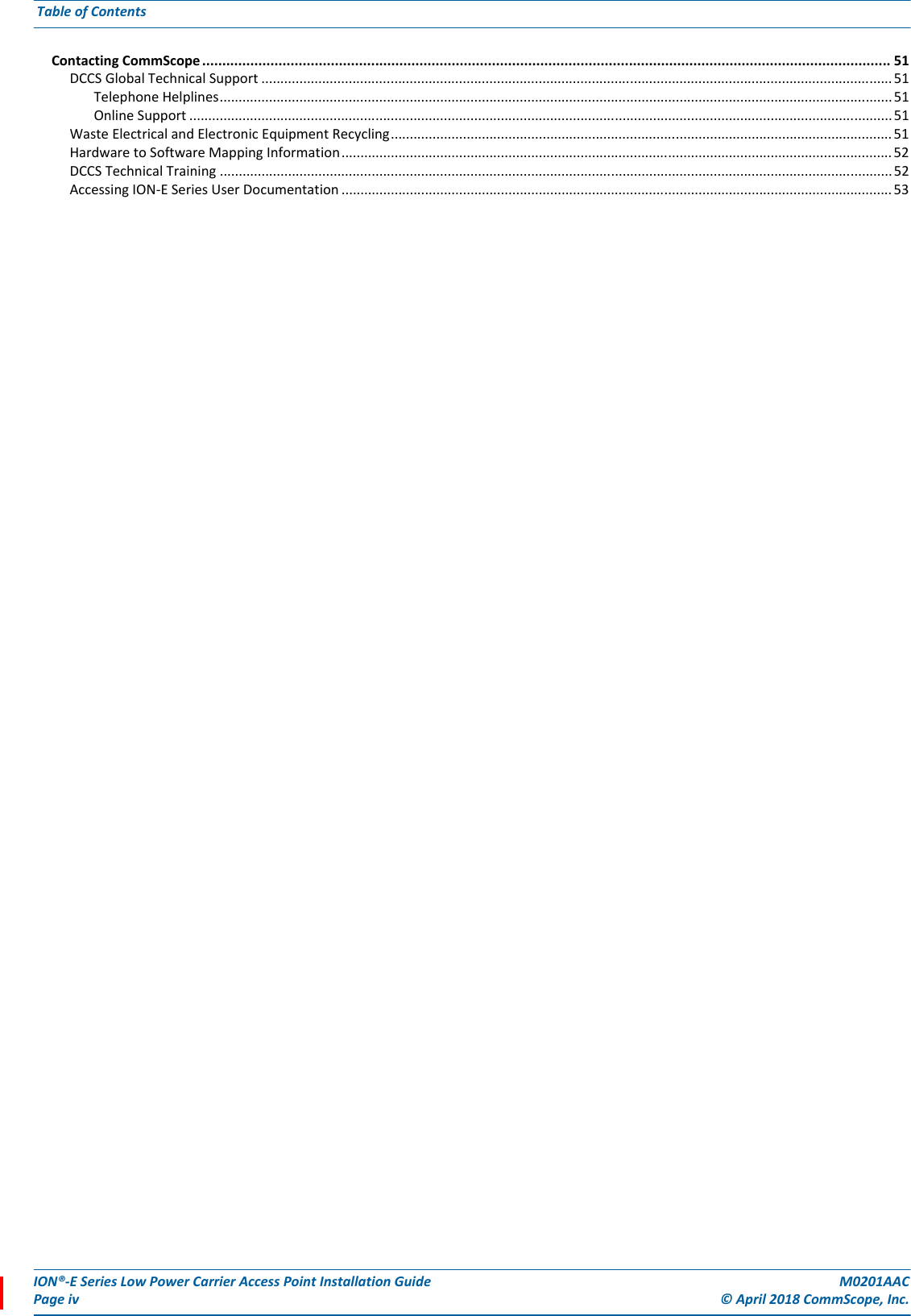
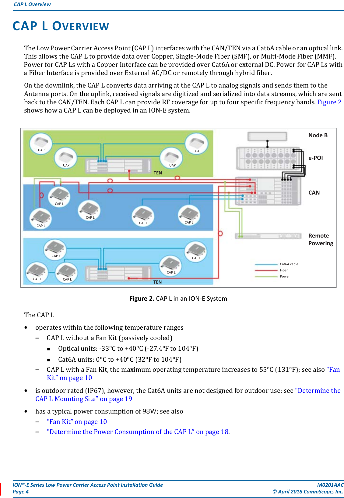
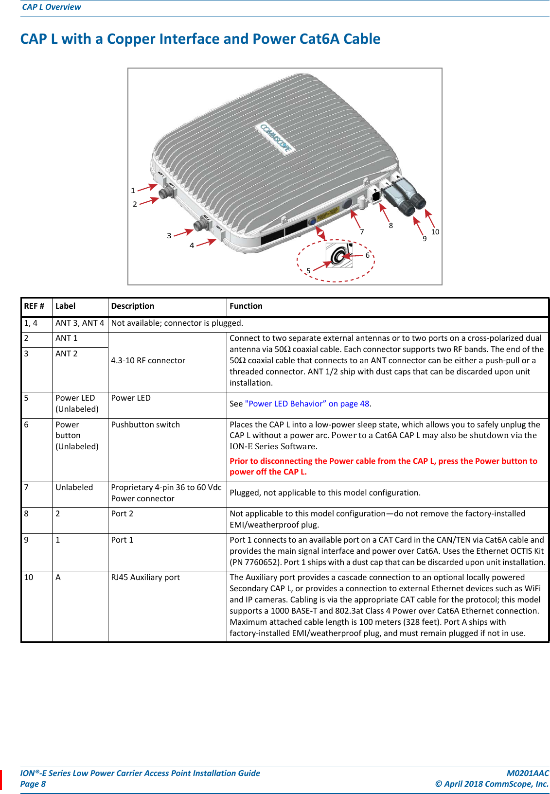
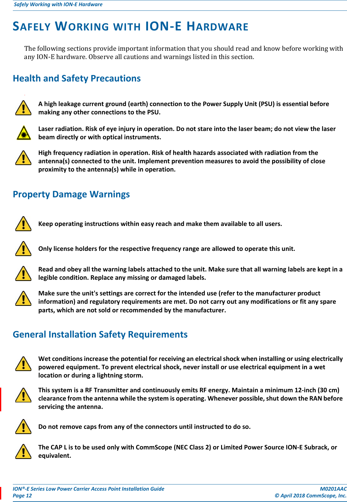
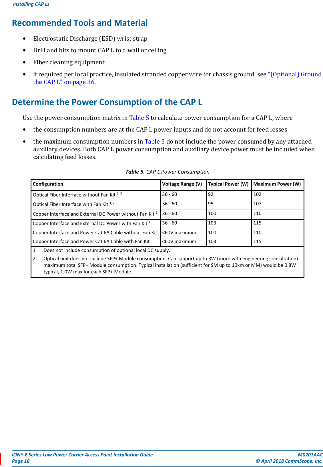
![M0201AAC ION®-E Series Low Power Carrier Access Point Installation Guide© April 2018 CommScope, Inc. Page 21Installing CAP LsFigure 5. Mounting Dimensions for a CAP L Mounted with the AC/DC Power Supply KitGeneral Mounting CautionsThefollowingcautionsapplytoallCAPLinstallations;theremaybeothermountingcautionsapplicabletoaspecificmountingoption,whichwillbedefinedintheapplicablemountingprocedure.Attach all CAP Ls securely to a stationary object as described in this installation guide.To maintain proper ventilation, keep at least 76 mm (3-inch) clearance around the CAP L. The installation site must be able to bear the weight of the CAP L; see Table 6 on page 19.120mm[4.724"]36.5mm[1.437"]48.69mm[1.917"]447.979mm[17.637"]24.106mm[0.949"]373.873mm[14.719"]87.44mm[3.443"]399.8mm[15.74"] 469.62[18.489"]35.727mm[1.407"]30mm[1.181"]2X401mm[15.787"]158.42mm[6.237"]188mm[7.402"]104.73mm[4.123"]31.5mm[1.24"]](https://usermanual.wiki/Andrew-Wireless-System/CAPL17E192325/User-Guide-3798386-Page-25.png)