Andrew Wireless System IONM8919P ION M remote unit for cellular networks User Manual User s Manual for Optical Remote Unit
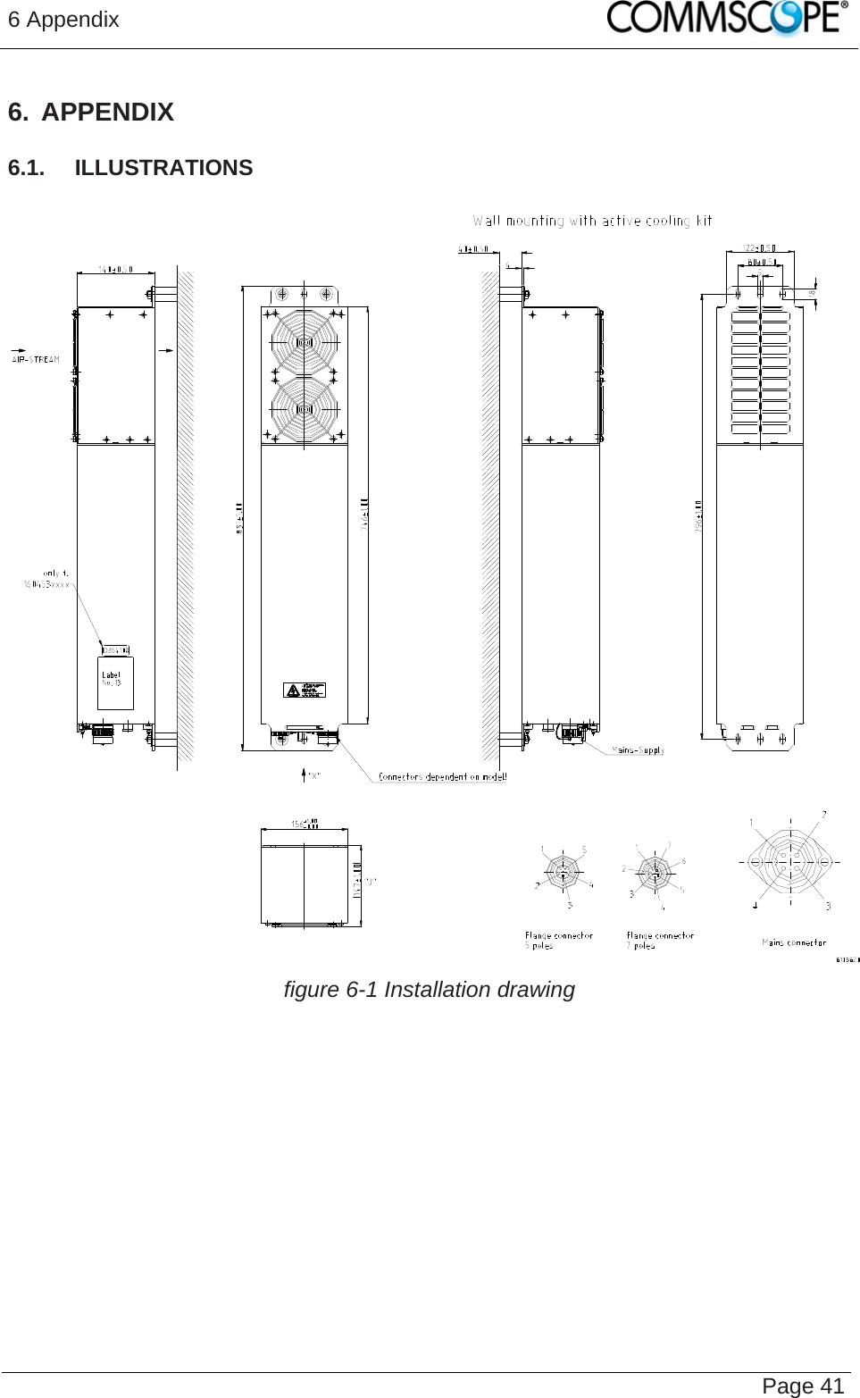
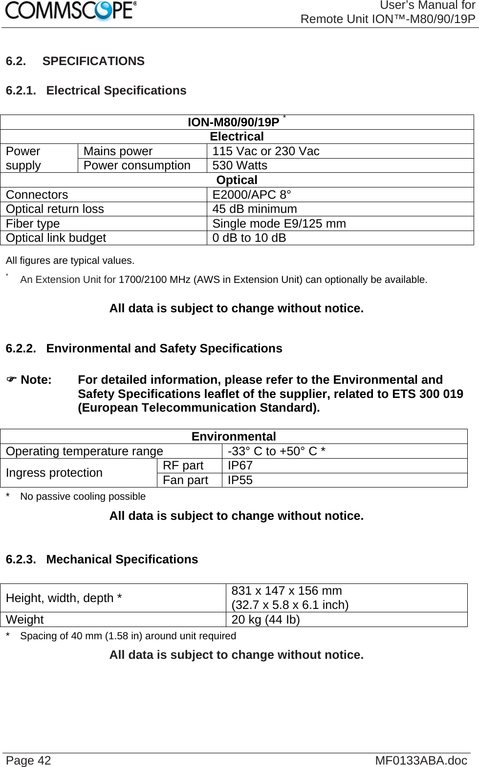
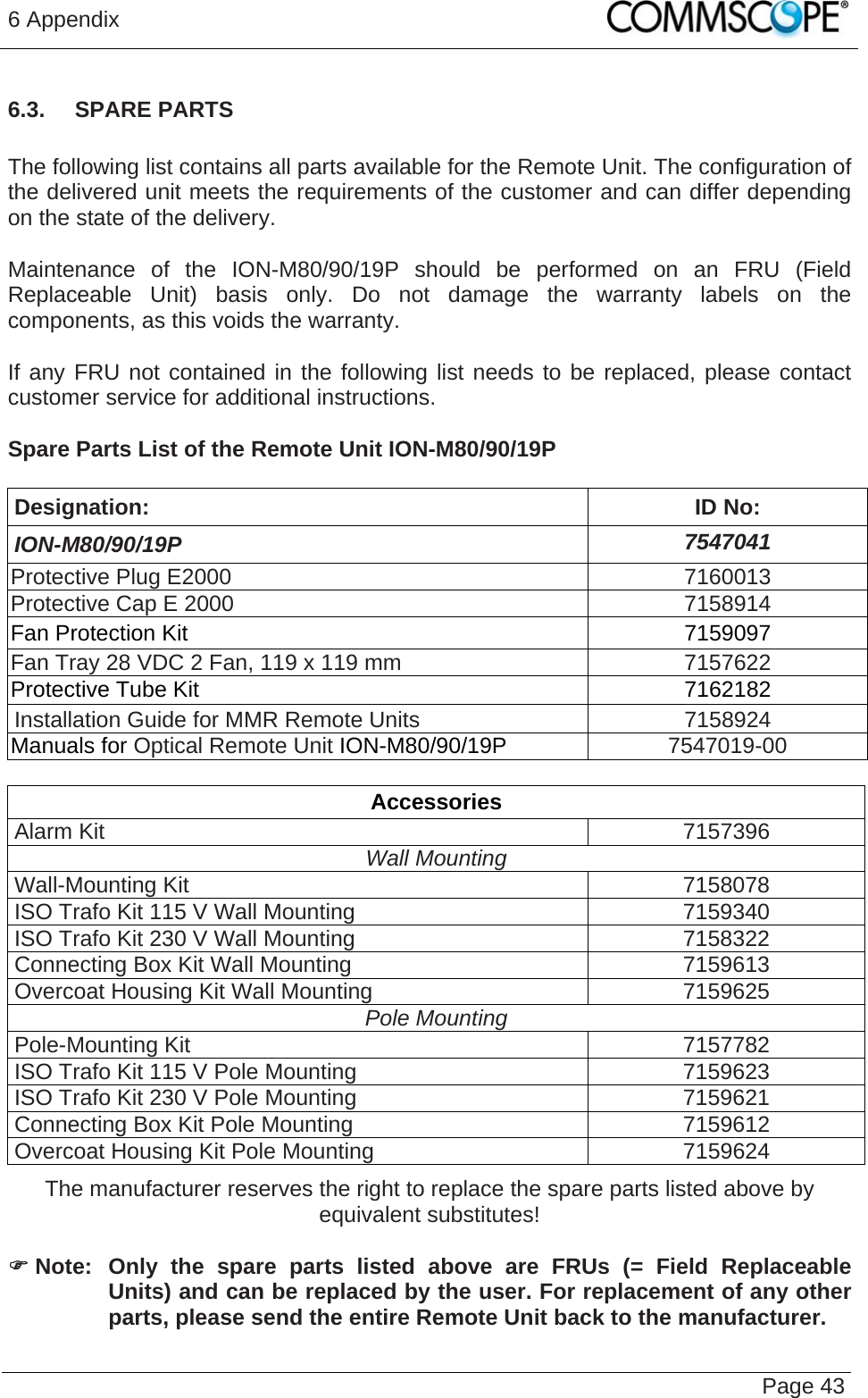
Andrew Wireless System ION M remote unit for cellular networks User s Manual for Optical Remote Unit
UserManual.wiki
>
Andrew Wireless System
>
IONM8919P User Manual
user manual
Navigation menu
Upload a User Manual
Namespaces
Wiki Guide
HTML
PDF
Info
Views
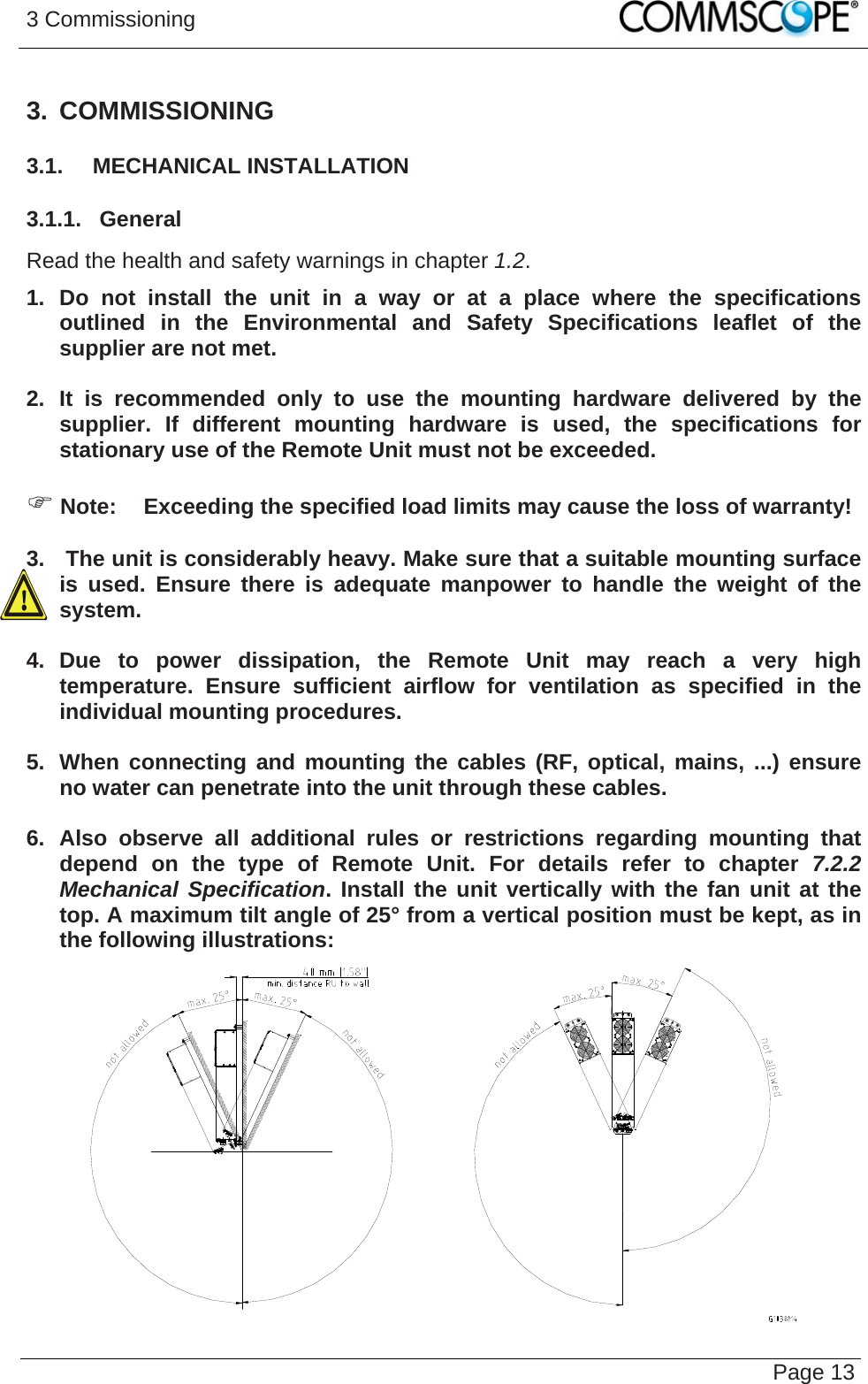
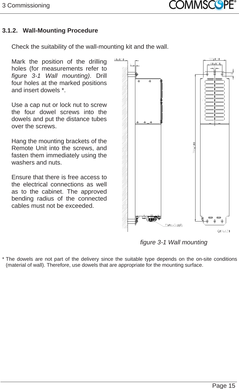
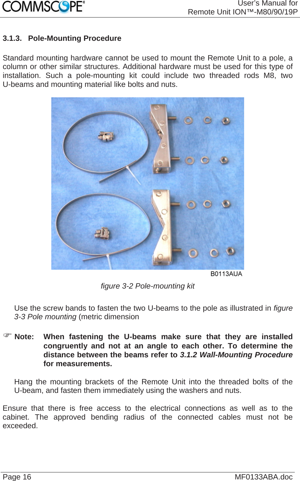
User Manual
Discussion / Help
Navigation