Andrew Wireless System IONM8PS ION-M Remote Unit for cellular systems User Manual User s Manual for ION M Remote Unit
Andrew Wireless System ION-M Remote Unit for cellular systems User s Manual for ION M Remote Unit
Contents
- 1. Installation Instruction
- 2. User Manual
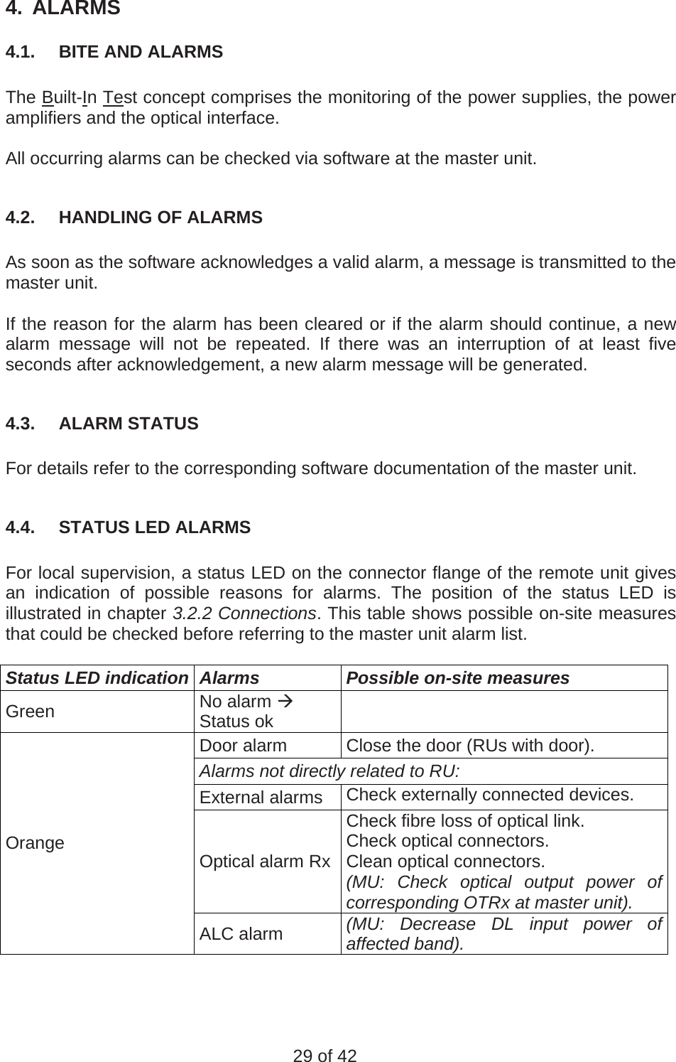
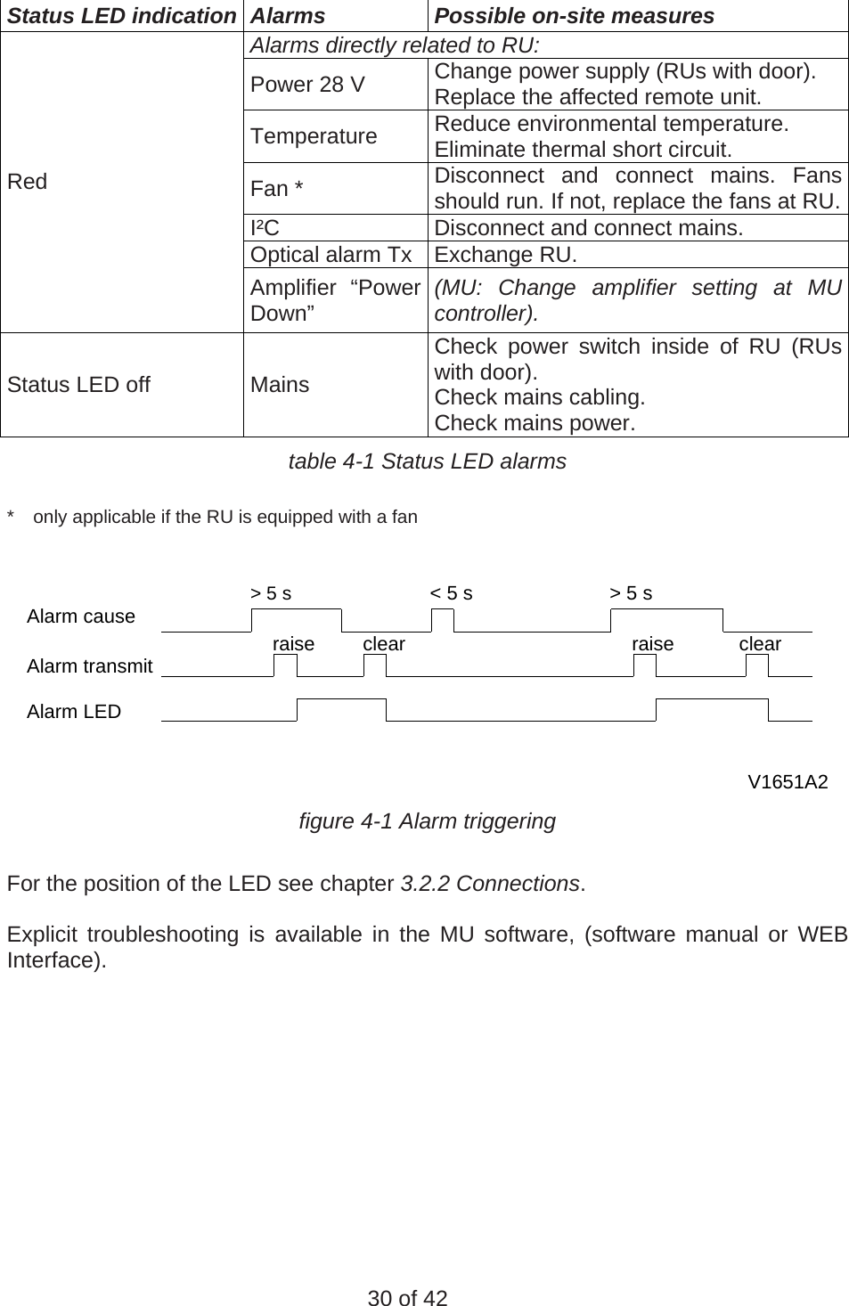
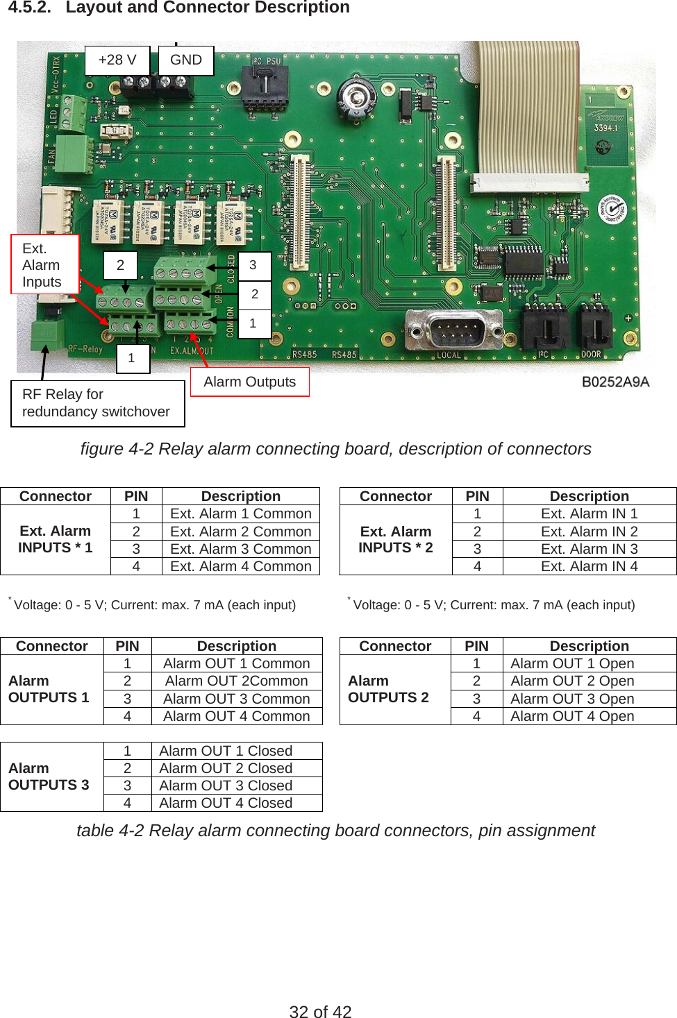
User Manual