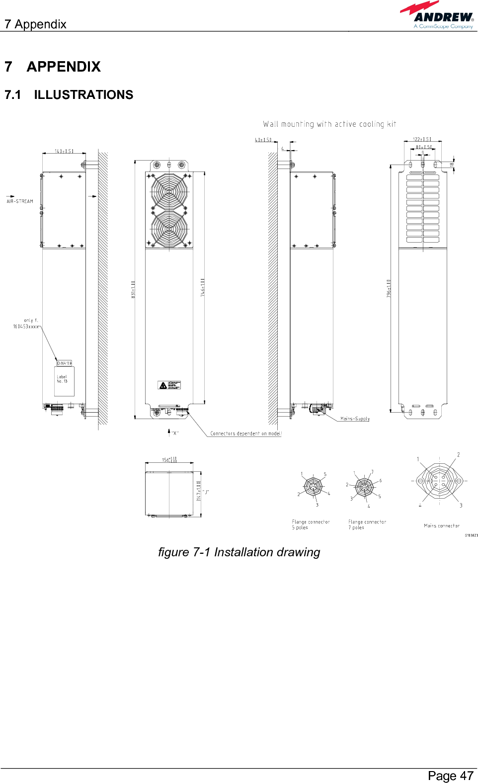
Andrew Wireless System M17P17P17P ION-M17P/17P/17P RF Repeater User Manual M0132AKA FCC
Andrew Wireless System ION-M17P/17P/17P RF Repeater M0132AKA FCC
UserManual.wiki
>
Andrew Wireless System
>
M17P17P17P User Manual
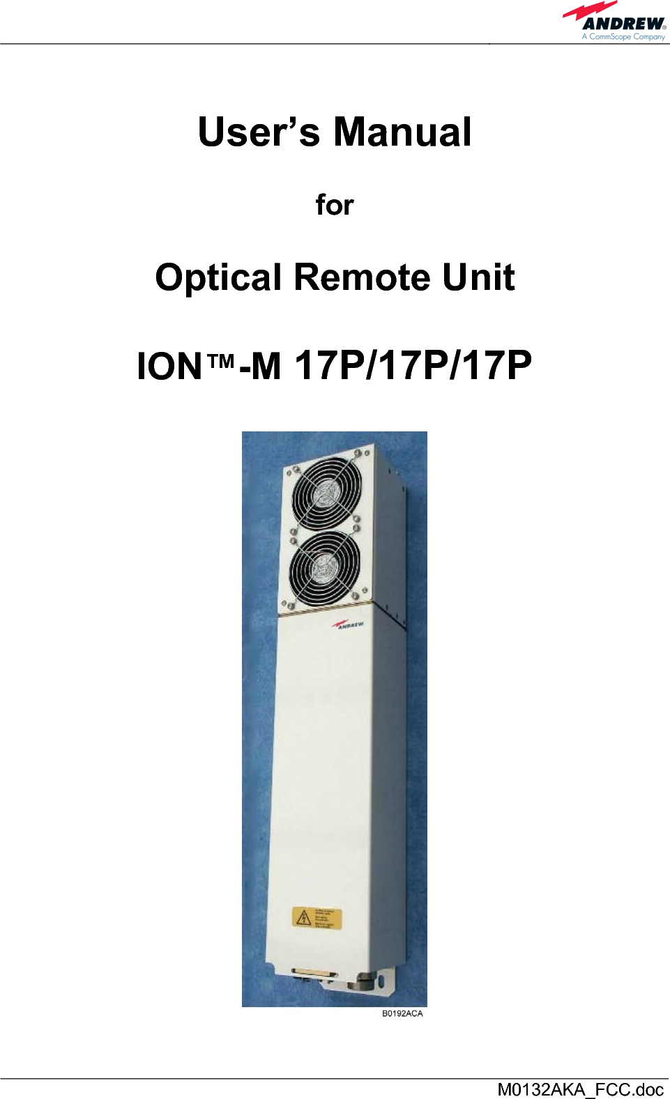
Users Manual
Navigation menu
Upload a User Manual
Namespaces
Wiki Guide
HTML
PDF
Info
Views
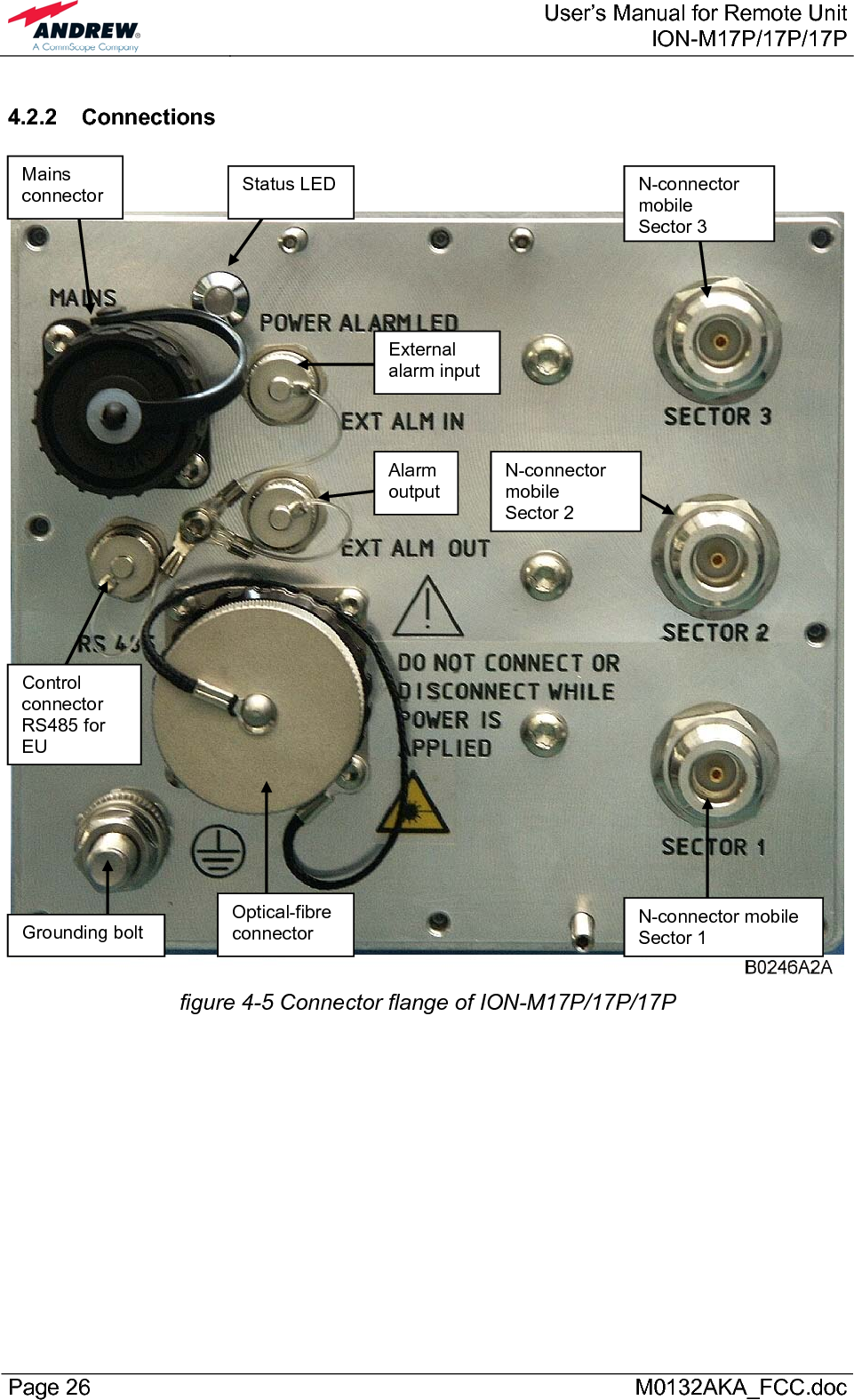
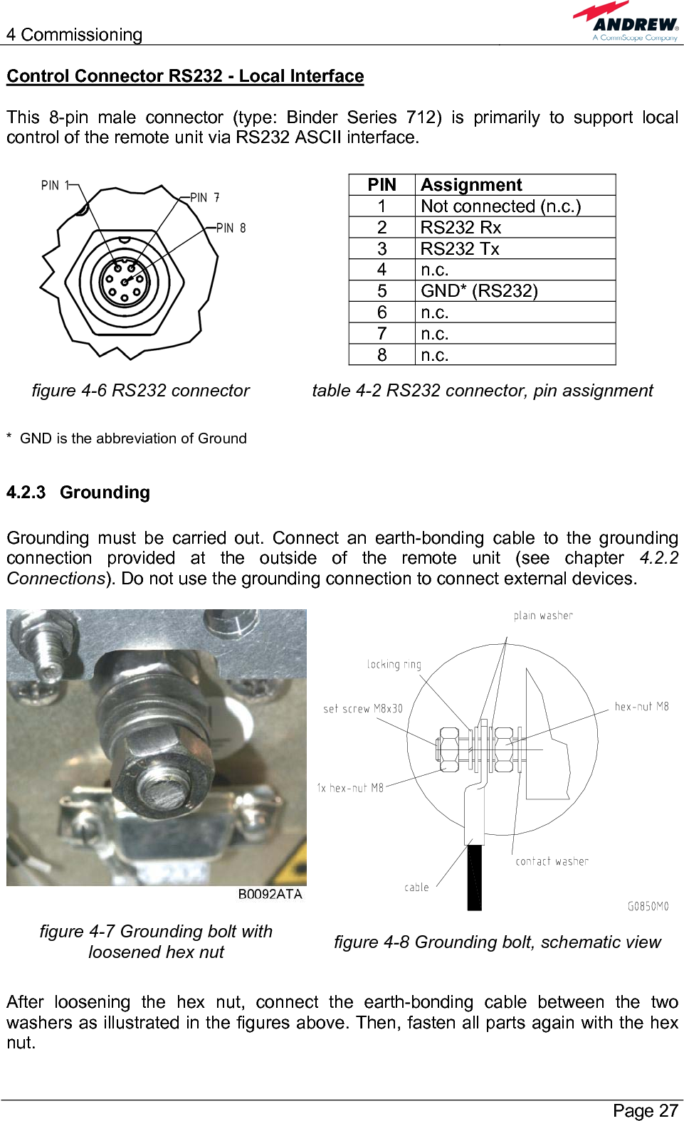
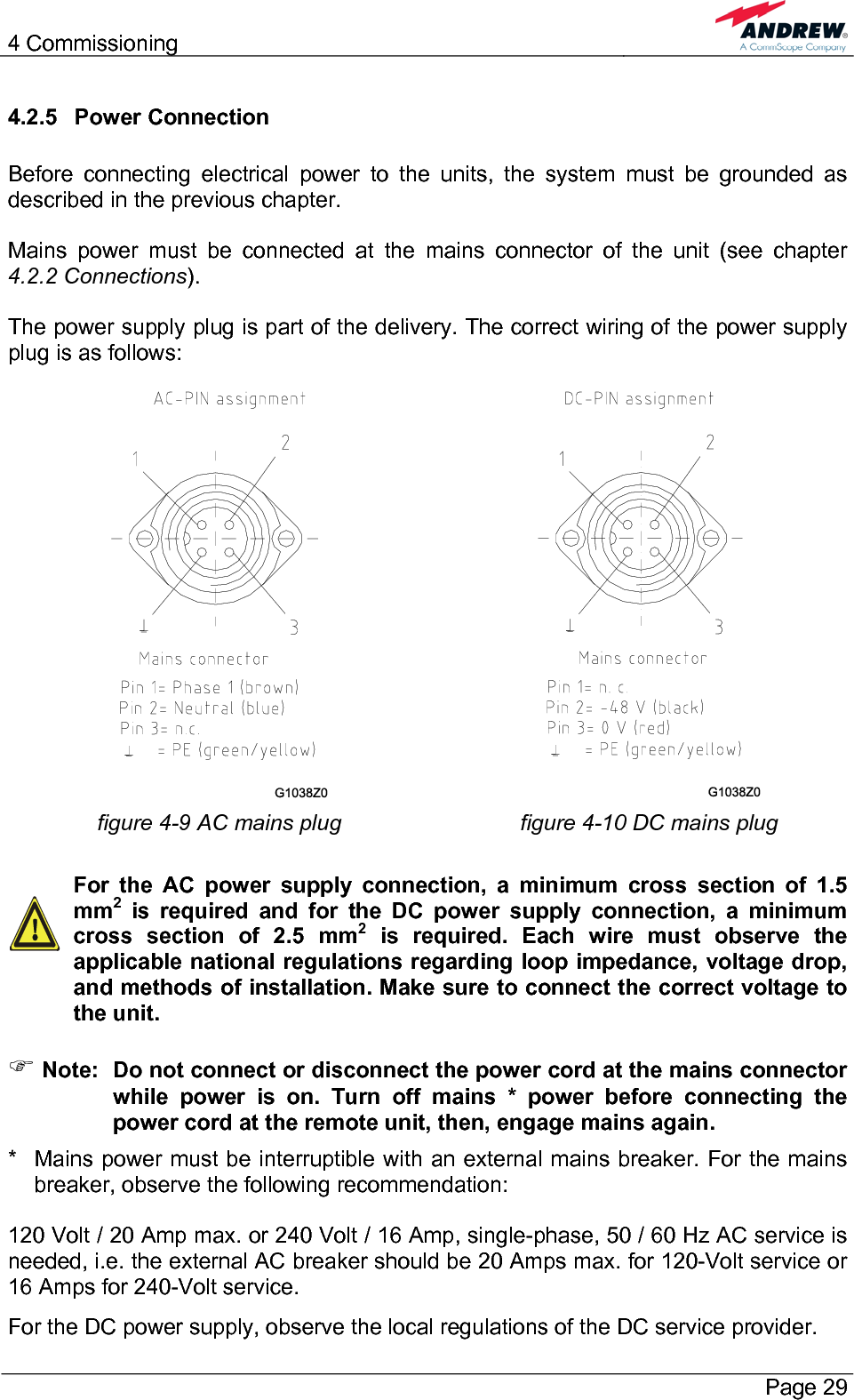
User Manual
Discussion / Help
Navigation